

Page 1

®
Home Appliances
IMPORTANT:
Gas Large Capacity Thin Twin
Washer•Dryer – 120 Volt
Installation Instructions
Gas Large Capacity Thin Twin
Read and save
these instructions.
IMPORTANT:
Installer: Leave Installation Instructions
with the homeowner.
Homeowner: Keep Installation Instructions
for future reference.
Save Installation Instructions for local
electrical inspector’s use.
www.whirlpool.com
Part No. 3395326 Rev. F
Page 2
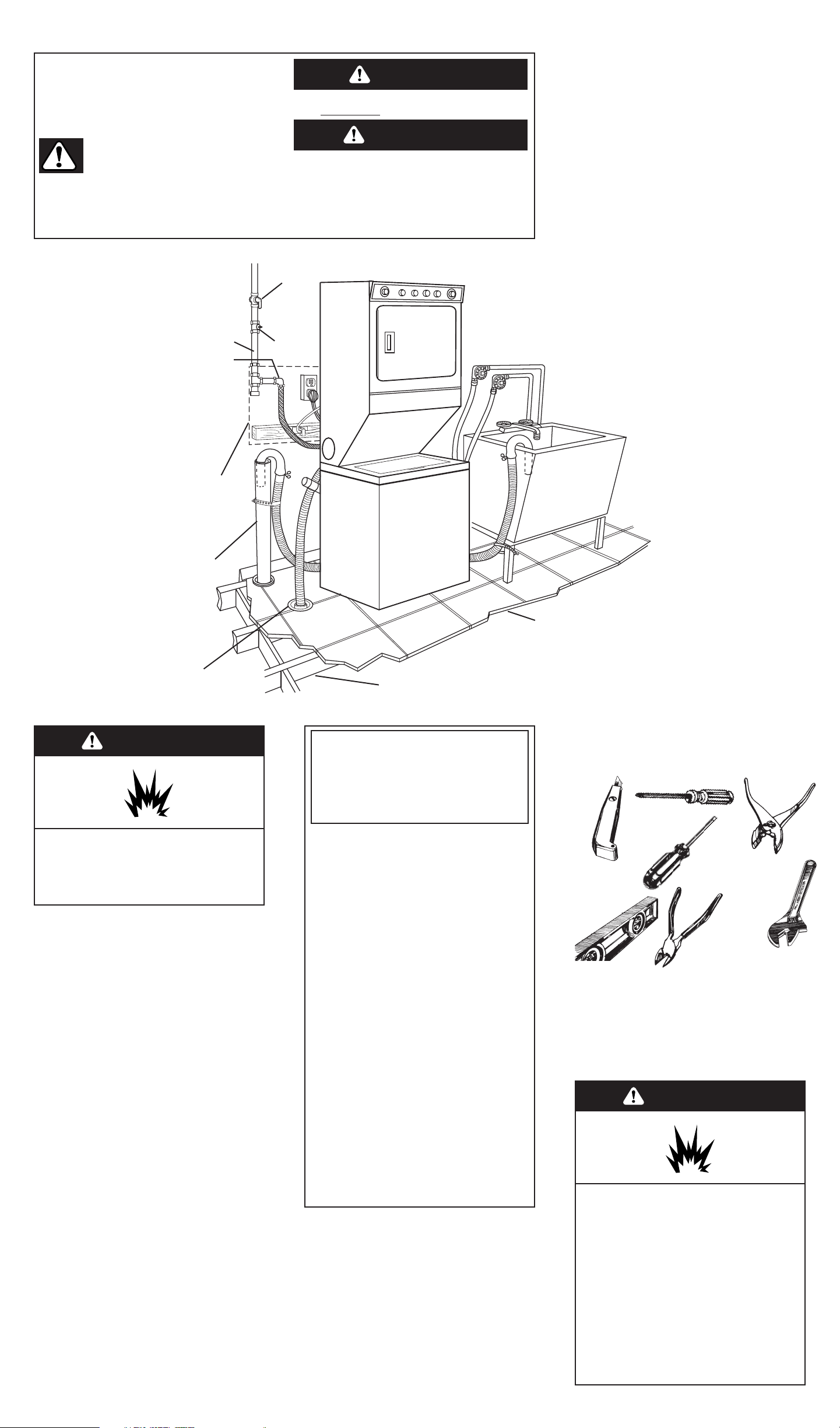
Panel A
Tools and materials
needed for installation:
Phillips screwdriver
diagonal
cutters
utility
knife
adjustable
wrench (two
may be
required)
flat-blade
screwdriver
level
pliers
A 1" x 4" x 24" board and fasteners are also
required (but are not included with this product).
Gas supply requirements
OBSERVE ALL GOVERNING CODES
AND ORDINANCES
Before you start...
Location: Should be large enough to fully
open dryer door to 90°. (See Panel G for
“Recessed and closet installation
instructions” and “Product dimensions.”)
WARNING
Explosion Hazard
Keep flammable materials and vapors,
such as gasoline, away from dryer.
Failure to do so can result in death,
explosion, or fire.
Grounded electrical
outlet is required. See
“Electrical
requirements.”
Check location where washer/dryer will
be installed. Proper installation is your
responsibility. The washer/dryer must not
be installed or stored in an area where it
will be exposed to water and/or
weather. Make sure you have
everything necessary for correct
installation.
Water heater: Set to deliver 140°F water to the
washer.
Laundry tub drain system: Needs a 20-gallon
laundry tub. Top of tub must be at least
34 inches high and no higher than 72 inches
from floor.
If a longer drain hose is needed, drain hose
(Part No. 388423) and hose extension kit (Part
No. 285442) are available from Whirlpoolauthorized parts distributors.
Dryer may be exhausted from the rear or
left or right side. Exhausting through the
side requires Part No. 3391335. (See
“Exhaust requirements,” Panels B
and C.)
Four-inch metal exhaust
vent is required.
SEE RECESSED AREA
INSTRUCTIONS ON PANEL G.
Important: Observe all governing
codes and ordinances.
gas supply line
coupling
38" min. to 41"
max.
from floor
Support: Floor must be sturdy enough
to support washer/dryer weight, with
water and clothes, of 500 pounds.
Level floor:
1-inch maximum slope
under entire washer/dryer.
gas shutoff
valve
Hot and cold
water faucets:
Must be within
4 feet of the
back of the
washer/dryer
and provide
water pressure
of 5 -100 PSI.
1/8-inch
NPT
plugged
tapping
rigid
gas
supply
line
Standpipe drain system: Needs
a two-inch diameter standpipe
with minimum carry-away
capacity of 17 gallons per
minute. Top of standpipe must
be at least 34 inches high and
no higher than
72 inches from floor.
Floor drain system requires a
siphon break, Part No. 285320,
available from a Whirlpoolauthorized parts distributor.
This appliance must be attached to
a wall. The cable bracket must be
secured to a wall stud within a
27-inch-wide area that is 28 inches
minimum to 41 inches maximum
from floor. (See Panel F.)
1/8-inch NPT plugged
tapping is required.
(See Panel B, Step L.)
Do Not store or operate washer/dryer below
32°F (some water may remain in washer).
Proper operation of dryer cycles requires
temperatures above 45°F. See Use & Care
Guide for “Winterizing” information.
Check code requirements: Some codes
limit or do not permit installation of clothes
dryers in garages, closets, mobile homes
and sleeping quarters. (Contact your local
building inspector.)
Check utilities: Proper gas, water and
electric supply connections must be
available.
WARNING: For your safety the
information in this manual
must be followed to minimize
the risk of fire or explosion or
to prevent property damage,
personal injury or death.
— Do not store or use gasoline
or other flammable vapors and
liquids in the vicinity of this or
any other appliance.
— WHAT TO DO IF YOU SMELL
GAS
• Do not try to light any
appliance.
• Do not touch any electrical
switch; do not use any
phone in your building.
• Clear the room, building or
area of all occupants.
• Immediately call your gas
supplier from a neighbor’s
phone. Follow the gas
supplier’s instructions.
• If you cannot reach your
gas supplier, call the fire
department.
— Installation and service must
be performed by a qualified
installer, service agency or
the gas supplier.
WARNING
Explosion Hazard
Use a new AGA or CSA approved gas
supply line.
Install a shut-off valve.
Securely tighten all gas connections.
If connected to LP, have a qualified
person make sure gas pressure does
not exceed 13" water column.
Examples of a qualified person include
licensed heating personnel, authorized
gas company personnel, and
authorized service personnel.
Failure to do so can result in death,
explosion, or fire.
Your safety and the safety of others are
very important.
We have provided many important safety messages
in this manual and on your appliance. Always read
and obey all safety messages.
This is the safety alert symbol.
This symbol alerts you to potential
hazards that can kill or hurt you and
others.
All safety messages will follow the safety alert
symbol and either the word “DANGER” or
“WARNING”. These words mean:
All safety messages will tell you what the potential
hazard is, tell you how to reduce the chance of
injury, and tell you what can happen if the
instructions are not followed.
You can be killed or seriously injured if you
don’t immediately
follow instructions.
You can be killed or seriously injured if you don’t
follow instructions.
WARNING
D ANGER
Page 3

Important: Observe all governing codes
and ordinances.
Exhaust your dryer to the outside.
Moisture and lint indoors may cause:
• Lint to gather around the dryer where
it can be fuel for a fire.
• Moisture damage to woodwork,
furniture, paint, wallpaper, carpet,
etc.
• Housecleaning problems and health
problems.
If the washer/dryer is installed in a
confined area such as a bedroom,
bathroom or closet, it must be
exhausted to the outside and provision
must be made for enough air for
ventilation. Check governing codes and
ordinances. Also refer to the “Recessed
and closet installation instructions” on
Panel G.
Dura Safe
TM
vent products are
recommended and are available from
your dealer. See Panel G.
Four-inch diameter vent is required.
Use a heavy metal vent. Do not use plastic or
metal foil vent.
• Do Not use non-metal flexible vent, or
exhaust hoods with magnetic latches.
• Do Not exhaust dryer into a chimney,
furnace, cold air vent, attic or crawl space,
or any other vent used for venting.
• Do Not install flexible vent in enclosed walls,
ceilings or floors.
Rigid metal vent is recommended to prevent
crushing and kinking.
Flexible metal vent must be fully extended
and supported when the dryer is in its final
position.
Remove excess flexible vent to avoid
sagging and kinking that may result in
reduced air flow.
An exhaust hood should cap the exhaust
vent to prevent rodents and insects from
entering the home.
Exhaust outlet hood must be at least 12
inches from the ground or any object that
maybe in the path of the exhaust (such as
flowers, rocks or bushes, etc.).
If using an existing exhaust system, clean lint
from entire length of system and make sure
exhaust hood is not plugged with lint.
Panel B
G.If the washer/dryer is installed in a
confined area such as a bedroom,
bathroom or closet, it must be
exhausted to the outside and provision
made for enough combustion air and
ventilation air. (Check governing codes
and ordinances. Also refer to the
section in this instruction covering
Recessed and closet installations.)
gas
supply
line
H.This washer/dryer is equipped
with its own permanent, flexible gas
connector, design-certified by CSA
International, for connecting the
appliance to the gas supply line.
I.If rigid pipe is
used as a gas
supply line, a
combination of
pipe fittings must
be used to
obtain an in-line
connection to
the washer/dryer.
J.Make sure the back and sides of
the cabinet are free of obstructions to
permit adequate clearance of air
openings for combustion air. (See
“Recessed and closet installation
instructions” for minimum spacing
requirements, Panel G.)
household rigid
gas supply pipe
K.For ease of installation, operating
and servicing (if ever needed),
adequate space should be provided
around the washer/dryer.
L.An 1/8-inch NPT plugged tapping,
accessible for test gauge connection,
must be installed immediately upstream
of the gas supply connector to the
dryer.
The dryer and its individual shutoff valve
must be disconnected from the gas
supply piping system during any
pressure testing of that system at test
pressures in excess of 1/2 psig (3.45 kPa).
The dryer must be isolated from the gas
supply piping system by closing its
individual manual shutoff valve during
any pressure testing of the gas supply
piping system at test pressures equal to
or less than 1/2 psig (3.45 kPa).
Electrical requirements
A three-wire, single-phase, 120-volt,
60-Hz, AC-only, 15- or 20-ampere, fused,
electrical supply is required. A timedelay fuse or circuit breaker is
recommended. If your home has a
circuit wired and fused for 20 amperes,
this is preferred. If you are installing a
new circuit, one wired and fused for
20 amperes is recommended. It is also
recommended that a separate circuit
serving only this appliance be provided.
Recommended ground method
For your personal safety, this appliance
must be grounded. This washer/dryer is
equipped with a power supply cord
having a 3-prong ground plug. To
minimize possible shock hazard, the
cord must be plugged into a mating,
3-prong, ground-type outlet, grounded
in accordance with the National
Electrical Code, ANSI/NFPA
70 — latest edition,** and all local codes
and ordinances. (See Figure 1.) If a
mating outlet is not available, it is the
personal responsibility and obligation of
the customer to have a properly
grounded, 3-prong outlet installed by a
qualified electrician.
3-prong
ground
plug
power
supply
cord
Figure 1
ground
prong
3-prong
ground-type
outlet
Exhaust requirements
A.This installation must conform with
American National Standard, National
Fuel Gas Code ANSI Z223.1 — latest
edition,* and all local codes and
ordinances.
B.The design of this dryer has been
certified by CSA International for use at
altitudes up to 10,000 feet above sea
level at the B.T.U. rating indicated on
the model/serial plate. Burner input
adjustments are not required when the
dryer is operated up to this elevation.
When installed above 10,000 feet, a four
C.Check that this
dryer is equipped with
the correct burner for
the particular type of
gas in the home.
Burner information will
be found on the rating plate in the door
well of the appliance. If this information
does not agree with the type of gas
available, see your dealer.
D.This dryer is equipped for use with
NATURAL GAS. It is certified by CSA
International for manufactured, mixed
and L.P. (propane or butane) gases with
appropriate conversion. No attempt
shall be made to convert the appliance
from the gas specified on the
model/serial rating plate for use with a
different gas without consulting the
service gas supplier or a Whirlpooldesignated service company.
Conversion must be done by a qualified
service technician. Gas conversion kit
part numbers are listed on the burner
bracket behind the access panel.
(See Panel E.)
E.Provide a rigid gas supply line to
the dryer location. When rigid pipe is
used, it should be 1/2-inch IPS. Pipe-joint
compounds resistant to the action of
L.P. gas must be used.
to
dryer
shutoff valve
“open” position
F. The supply line shall be equipped
with a shutoff valve. This valve should be
located in the same room as the
washer/dryer and should be in a
location that allows ease of opening
and closing. Do Not block access to the
shutoff valve.
Important: Observe all governing codes
and ordinances.
If codes permit and a separate ground
wire is used, it is recommended that a
qualified electrician determine that the
ground path is adequate.
WARNING
Electrical Shock Hazard
Plug into a grounded 3-prong outlet.
Do not remove ground prong.
Do not use an adapter.
Do not use an extension cord.
Failure to follow these instructions can
result in death, fire, or electrical shock.
Fire Hazard
Use a heavy metal vent.
Do not use a plastic vent.
Do not use a metal foil vent.
Failure to follow these instructions
can result in death or fire.
percent (4%) reduction of the burner
B.T.U. rating shown on the model/serial
plate is required for each 1,000 foot
increase in elevation. For assistance
when converting to other gas types
and/or installing above 10,000 feet
elevation, contact your local service
company.
WARNING
Copies of the standards listed may be obtained from:
*CSA International
8501 East Pleasant Valley Road
Cleveland, Ohio 44131-5575
**National Fire Protection Association
Batterymarch Park
Quincy, Massachusetts 02269
Use pipe-joint
compound.
Adapter
supplied
Do Not use
pipe-joint
compound.
flexible gas
connector
Page 4
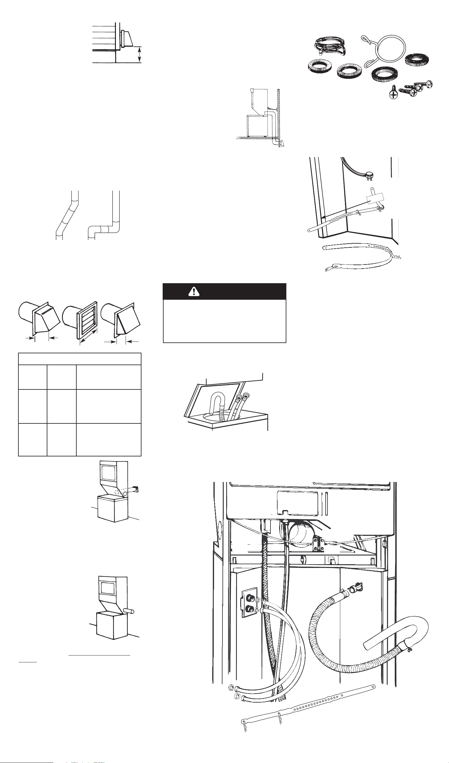
The exhaust vent can be
routed up, down, left,
right or straight out the
back of the
washer/dryer. Space
requirements are
provided on Panel G of
the Installation
Instructions and on the
rear panel of the
washer/dryer.
Four-inch outlet hood is preferred.
However, a 2-1/2-inch outlet exhaust
hood may be used. A 2-1/2-inch outlet
creates greater back pressure than
other hood types.
Exhausting the dryer
through the side of the
washer/dryer requires
the use of Side Exhaust
Kit, Part No. 3391335.
Follow kit installation
instructions for proper
exhaust installation.
For exhaust systems
not covered by the
exhaust length chart, see Whirlpool
Service Manual, Exhausting Whirlpool
Dryers
, Part No. 603197, available from
your Whirlpool parts distributor.
A closet installation must be exhausted
outside. See “Recessed and closet
installation instructions” on Panel G for
adequate unobstructed air opening
requirements.
Panel C
4"
4"
Rear, Side or Bottom Exhaust
2-1/2"
MAXIMUM
LENGTH OF
4" DIA. RIGID
METAL VENT
MAXIMUM
LENGTH OF
4" DIA. FLEXIBLE
METAL VENT
42 FT.
34 FT.
26 FT.
26 FT.
21 FT.
16 FT.
0
1
2
0
1
2
Number
of 90°
Turns
Now start...
With washer/dryer in laundry area.
Truck only from rear to prevent product
damage.
1.Open washer lid. Take hoses and
parts packages out of basket. Close lid.
• 1 hose clamp
• 4 flat, water-hose washers
• 4 cable-bracket screws
• 1 small clamp
2.Remove parts from package.
Check that all parts were included.
3.Pull to completely remove the
shipping strap with 2 cotterpins from the
inside of the washer/dryer.
Save the shipping strap for use in Step 18.
Numbers
correspond
to steps.
Flexible gas
connector must be
connected in a
single, natural loop.
Cable bracket must be
mounted to a 1" x 4"
board, 24" long, that is
securely mounted
across two wall studs or
on a concrete wall. (See
Panels D and F.)
Pull shipping strap
with 2 cotterpins
completely out of
washer.
10.
19.
30.
20.
21.
22.
23.
24.
14.
5.
7.
13.
6.
3.
5.
8.
11.
18.
17.
15.
Use new hose and washers that came with
your washer/dryer.
Replace inlet hoses after 5 years of use
to reduce the risk of hose failure. Inspect
and replace inlet hoses if bulges, kinks,
cuts, wear, or leaks are found. When
replacing your inlet hoses, mark the
date of replacement on the label with a
permanent marker.
Pull the
shipping
strap
completely
out of the
washer.
Excessive Weight Hazard
Use two or more people to move and
install washer/dryer.
Failure to do so can result in back or
other injury.
WARNING
better
good
exhaust air flow
Plan installation to use the fewest
number of elbows and turns.
Maximum length of the exhaust system
depends upon the type of vent used,
number of elbows and the type of
exhaust hood. The maximum length for
both rigid and flexible vent is shown in
the chart.
Replace any plastic or
metal foil vent with rigid
metal or flexible metal
vent.
Use clamps to seal all
joints. Do not use duct
tape, screws or other
fastening devices that extend into the interior
of the vent to secure vent.
Service check: Back pressure in any exhaust
system used must not exceed 0.6 inches in
water column measured with an incline
manometer at the point that exhaust vent
connects to dryer.
12"
minimum
Mobile home installation
This appliance is suitable for mobile
home installations. The installation of the
washer/dryer must conform to the
Manufactured Home Construction and
Safety, Title 24 CFR, Part 3280 (formerly
the Federal Standard for Mobile Homes
Construction and Safety, Title 24, HUD
Part 280, latest edition).
For all installations, this
appliance MUST be
fastened to the wall with
cable bracket and MUST
be exhausted to the
outside. Exhaust system
hardware is available
through your Whirlpool
dealer.
Mobile home exhaust requirements: The
washer/dryer must have an outside
exhaust. If the dryer is exhausted
through the floor and the area under
the mobile home is enclosed, the
exhaust system must terminate outside
the enclosed area. Extension beyond
the enclosure will prevent lint and
moisture buildup under the mobile
home.
4.Tilt washer/dryer forward. Check
that rear leveling legs move up and
down freely so that washer/dryer can
be properly leveled in Step 15.
Page 5
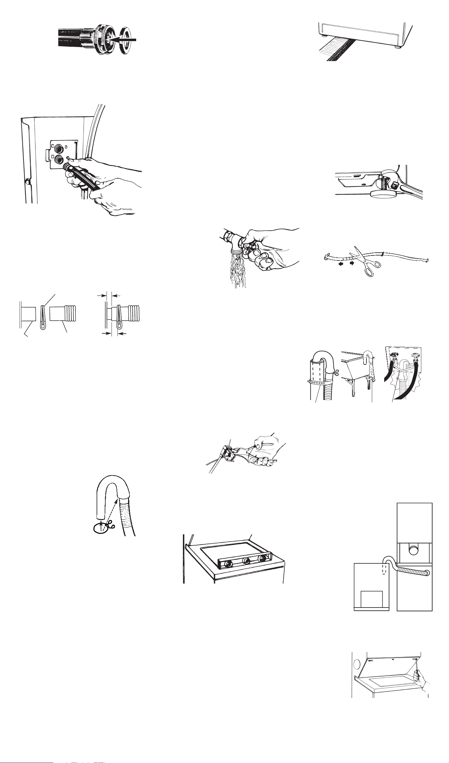
Panel D
Inlet valves are
plastic. Do not
strip or
crossthread.
6.Attach hose to bottom inlet valve
opening first; then second hose to top
inlet valve. Tighten couplings by hand.
Then use pliers to make an additional
two-thirds turn.
IMPORTANT: THIS PROCEDURE
MUST BE FOLLOWED TO ASSURE
PROPER INSTALLATION.
8.Standpipe or
laundry tub drain system:
Open clamp and slide
over “hook” end of drain
hose to secure the rigid
and corrugated
sections together.
7.To prevent the drain hose from
coming off or leaking, it must be
installed per the following instructions:
1. Wet the inside end of the drain
hose with tap water. DO NOT USE
ANY OTHER LUBRICANT.
2. Squeeze ears of clamp with pliers
to open and place clamp over the
end of the drain hose.
3. While holding clamp open, work
end of drain hose onto drain
connector.
4. Position clamp over the drain hose
area marked “clamp.” Release
clamp. Clamp should be 1/4 inch
from end of drain hose.
9.In a 24-inch-wide area that will be
behind the washer/dryer, securely
mount the 24-inch-long, 1-inch x 4-inch
board across two wall studs or on a
concrete wall so that it is 28 inches
minimum above the floor and no more
than 41 inches above the floor. Attach
the cable bracket to the 1-inch x 4-inch
board with four screws. (See Panel F.)
10.Slide washer/dryer onto
cardboard or hardboard before moving
across floor. If you have room to work
from either side of the washer/dryer,
move washer/dryer close to final
position so you can easily complete the
following steps. (Go to Step 11.)
If you are working in a closet or
recessed area, move the washer/dryer
into its final position and remove
cardboard or hardboard from under
washer/dryer. Remove the access
panel by removing three Phillips-head
screws and one bumper, located at the
top of the access panel. Set panel,
screws and bumper aside. (See Step
19.) Complete the following steps
through the access area.
11.Put “hook” end of drain hose
into laundry tub or standpipe. Check for
proper length of drain hose.
DO NOT FORCE EXCESS LENGTH OF
DRAIN HOSE DOWN THE STANDPIPE. THIS
COULD CAUSE SIPHONING.
12.Before
attaching water
inlet hoses, run
water through both
faucets into a
bucket. This will get
rid of particles in
water lines that might
clog hoses. Mark
which is the hot water faucet.
Replace inlet hoses after 5 years of use
to reduce the risk of hose failure. Inspect
and replace inlet hoses if bulges, kinks,
cuts, wear, or leaks are found. When
replacing your inlet hoses, mark the
date of replacement on the label with a
permanent marker.
13.Attach bottom hose (inlet
marked “H”) to hot water faucet.
Attach top hose (inlet marked “C”) to
cold water faucet. Tighten the coupling
to the faucet by hand. Use pliers to
make final two-thirds turn.
Move washer/dryer to its permanent
location. Remove cardboard from under
washer/dryer.
14.Cut the plastic strap securing
the cable wire bracket to the power
supply cord and discard. DO NOT CUT
CABLE. Remove the power supply cord
from the bracket. Attach the cable wire
bracket to the wall. Check that bracket
is secure. (See Panel F.)
15.Tilt washer/dryer forward raising
back legs 1 inch off of floor to adjust
rear, self-leveling legs. Gently lower
washer/dryer to floor. Check levelness
of the washer/dryer by placing a
carpenter’s level on top of the washer,
first side to side; then front to back. If
washer/dryer not level, check that rear
leveling legs move up and down freely.
If washer/dryer is level, go to Step 17.
Insert corner posts 6 inches
from left leg. Do Not insert
corner posts in the center of
the washer/dryer.
16.If it is not level, carefully tilt
washer/dryer backward until front of
washer/dryer is 3-4 inches off of floor.
Insert 4 corner posts under washer/dryer
about 6 inches from the left leg. Loosen
nuts on each front leg. Adjust the front
legs up or down. Tilt washer/dryer
backward and remove corner posts.
Gently lower the washer/dryer to the
floor. Repeat Step 15. If it is still not level,
repeat Step 16 and then Step 15 until
washer/dryer is level.
17.When washer/dryer is level, use
wrench to turn nuts on front legs up
tightly against washer/dryer base. If nuts
are not tight against washer/dryer base,
the washer/dryer may vibrate.
18.Measure and mark a point
approximately 16 inches from the plug
end of the shipping strap. Cut the
shipping strap at this point.
Check that hose is not twisted or
kinked and is securely in place.
A
B
C
strap strap
Put “hook” end of drain hose in tub or
standpipe. Tightly wrap the shipping
strap around the drain hose and tub or
standpipe or inlet hose as shown in
Figures A-C. Push plug into the nearest
hole in the shipping strap.
Hose must be cut exactly to length so
“hook” end is held tightly over edge of
standpipe.
If drain hose cannot be strapped in
place, it must be cut exactly to length
so the “hook” end is held tightly over the
edge of the tub or
standpipe.
If a longer drain hose is
needed, drain hose (Part No.
388423) and hose extension
kit (Part No. 285442) are
available from authorized
parts distributors. If drain
hose must be
shortened, use
hose kit (Part
No. 285442).
Note: If
washer/dryer
is moved to
adjust drain
hose, the washer/dryer must be leveled
again. Repeat Steps 15-17. Place
cardboard under the washer/dryer and
carefully move washer/dryer to avoid
damaging floor covering.
strap
19.If you did not remove the
access panel in Step 10, remove three
Phillips-head screws and one bumper,
located at the top of the access panel.
Set the panel, screws and bumper
aside.
Figure D
16"
drain hose
connector
clamp
drain hose
1/4"
1/4"
max.
16"
5.Insert a flat washer into each end
of the inlet hoses. Check that washers
are firmly seated in couplings.
washer
coupling
16"
Page 6
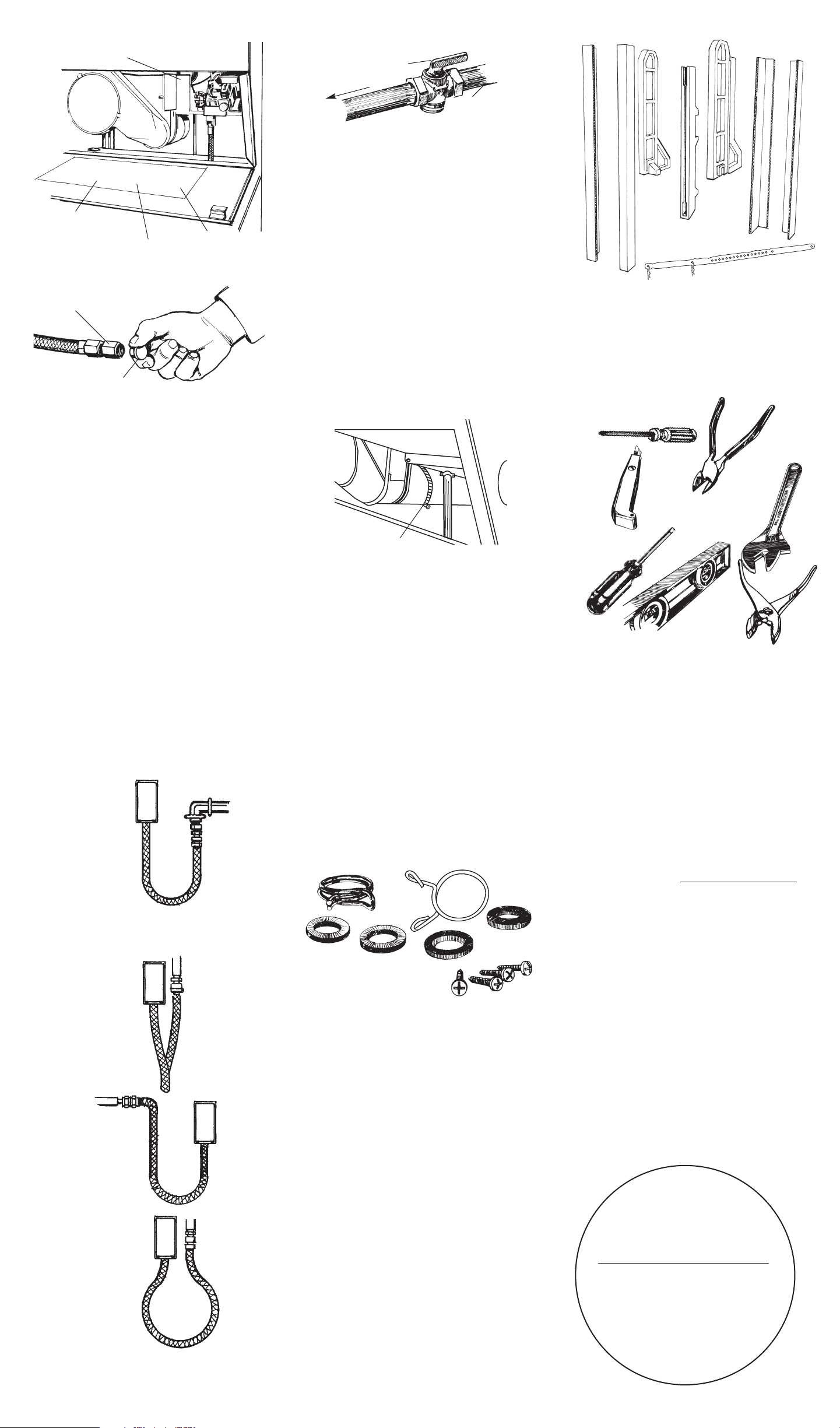
Panel E
20.Remove the red cap from the
flexible gas connector. Remove the
adapter from the flexible gas
connector. (It may be necessary to use
two adjustable wrenches.) Install the
adapter on the rigid gas supply line
using pipe-joint compound. Attach the
flexible gas connector to the adapter.
Do Not use pipe-joint compound. (See
Step I, Panel B.)
Connect dryer to rigid gas supply line so
that there is a natural loop in the flexible
gas connector from the dryer. The
couplings should be in the same plane
and positioned just far enough apart to
allow the flexible gas connector from
the dryer to loop without any strains on
the line. The flexible gas connector must
NOT be twisted, kinked or attached with
any sharp bends. Use pipe-joint
compound resistant to the action of L.P.
gas for all gas connections, except at
the flexible gas connector to the
adapter. (See Step I, Panel B.)
A rigid gas supply line to washer/dryer
location must be used.
conversion kit
part nos.
access
panel
cable
requirements
exhaust
requirements
wiring
diagram
The wiring diagram is located on the back of the
access panel. Read before installing or servicing.
adapter
red cap
Right method
Wrong methods
The flexible gas
connector MUST
be connected in a
single, natural
loop.
Gas supply line
coupling should be
38 inches min. to 41
inches max. from
floor and against
(parallel to) wall.
DO NOT OFFSET
COUPLINGS — this
causes twisting and
straining of the
flexible gas
connector, which
may cause
premature failure of
the connector.
A sharp bend in the
flexible gas
connector at the
couplings causes
straining and
twisting, which may
result in premature
failure of the
coupling.
Placing the
couplings too close
together causes
double bends that
may result in fatigue
failure of the fittings.
21.All connections must be
wrench-tightened. Open the shutoff
valve in the gas supply line.
23.Determine the length of exhaust
vent that is needed to connect the dryer
to the exhaust hood. (See “Exhaust
requirements,” Panels B and C.)
22.Use a brush and liquid
detergent to test all gas connections for
leaks. Bubbles around connections will
indicate a leak. If a leak appears, shut
off gas valve controls and adjust
connections. Then check connections
again.
24.Connect exhaust vent to
washer/dryer and then to the exhaust
hood.
• Use the straightest path possible to
avoid 90° turns.
• Use clamp to seal all joints in the
exhaust system.
• Use caulking compound to seal
exterior wall opening around exhaust
hood.
25.CHECK ELECTRICAL
REQUIREMENTS. BE SURE YOU HAVE
CORRECT ELECTRICAL SUPPLY AND
RECOMMENDED GROUND METHOD.
Check the Installation Instructions to see
that you have completed each step.
Complete any missed steps before you
continue.
26.Check that all parts are now
installed. (See parts list, Panel C.) If there
is an extra part, go back through steps
to see which step was skipped.
27.Check that you removed all
the shipping pieces including the
shipping strap with its 2 cotterpins and
plug. Dispose of all materials in proper
manner.
If you do not remove the shipping strap, your
washer/dryer may “walk” away from its
location.
28.Check that you have all of your
tools.
29.Turn on water faucets and
check for leaks. Tighten couplings if
there is leaking. Do Not overtighten; this
could cause damage to faucet.
30.Replace access panel. Be sure
to tighten the three Phillips-head screws
at the top of the access panel. Replace
the bumper under the center screw.
31.Read the Use and Care Guide
to fully understand your new
washer/dryer. Open dryer door. Check
to be sure lint screen is in its proper
position. Wipe out drum.
32.Plug power supply cord into
grounded outlet. Now start the washer
and allow it to complete the regular
cycle.
33.Start dryer to remove air from
the gas supply line. Using a full heat
cycle (not the air cycle), let the dryer
run for at least five minutes. If the burner
does not ignite and you can feel no
heat inside the dryer, shut off the dryer
for five minutes. Check that all supply
valve controls are in the “ON” position
and that the power supply cord is
plugged in. Repeat the five-minute test.
You have
successfully installed your
new, Whirlpool washer/dryer.
To get the most efficient use from
your new washer/dryer, read your
Whirlpool Use and Care Guide
.
Congratulations!
Keep Installation Instructions nearby
where you can refer to them.
They’ll make reinstalling your
Whirlpool washer/dryer in
another home as easy as
the first installation.
Phillips screwdriver
diagonal
cutters
utility
knife
adjustable
wrench (two
may be
required)
flat-blade
screwdriver
level
pliers
gas
supply
line
to
dryer
shutoff valve
“open” position
clamp
Page 7
Panel F
When moving the washer/dryer...
• Disconnect the power supply cord,
then tape securely to the
washer/dryer.
• Shut off the gas supply valve in the gas
supply line.
• Disconnect the flexible gas connector
and fittings from gas supply line and
cap the gas supply line.
• Tape the flexible gas connector to
back panel of the washer/dryer. DO
NOT DISCONNECT THE FLEXIBLE GAS
CONNECTOR FROM THE
WASHER/DRYER.
• Unscrew the cable bracket from the
wall stud or concrete wall. Save the
bracket and four screws.
• Tape the drum to the front panel. Tape
the lint screen in place. Tape the dryer
door closed.
• Wedge a blanket between the tub ring
and cabinet top to restrict tub
movement.
Before installing the washer/dryer in your
new home, check with your gas supplier
or dealer to see that your dryer is
equipped with the correct burner for the
particular type of gas in your new home.
Burner information may be found on the
rating plate in the door well of the dryer.
If washer/dryer does
not operate properly...
Check the following to be sure that:
1. Electric supply is connected.
2. House fuse or circuit breaker is intact
and tight.
3. Washer lid or dryer door is closed.
4. Controls are set in a running or “ON”
position.
5. Dryer start button has been firmly
pushed.
6. Make sure shipping strap has been
completely removed and was used to
secure the drain hose to the tub or
standpipe.
7. Gas shutoff valve is open in supply line.
If you need assistance...
The Whirlpool Customer Interaction
Center will answer any questions about
operating or maintaining your
washer/dryer not covered in the
Installation Instructions. The Whirlpool
Customer Interaction Center is open
24 hours a day, 7 days a week. Just dial
1-800-253-1301 — the call is free.
When you call, you will need the
washer/dryer model number and serial
number. Both numbers can be found on
the model/serial rating plate located in
the door well behind the dryer door and
on front of opening.
If you need service...
In the event that your Whirlpool
appliance should need service, call the
dealer from whom you purchased the
appliance or a Whirlpool-designated
service company. A Whirlpooldesignated service company is listed in
the Yellow Pages of your telephone
directory under “Appliances —
Household — Major — Service or Repair.”
You can also obtain the service
company’s name and telephone
number by dialing, free, within the
continental United States, the Whirlpool
Customer Interaction Center telephone
number, 1-800-253-1301. A special
operator will tell you the name and
number of your nearest Whirlpooldesignated service company.
Maintain the quality built into your
Whirlpool appliance — call a Whirlpooldesignated service company.
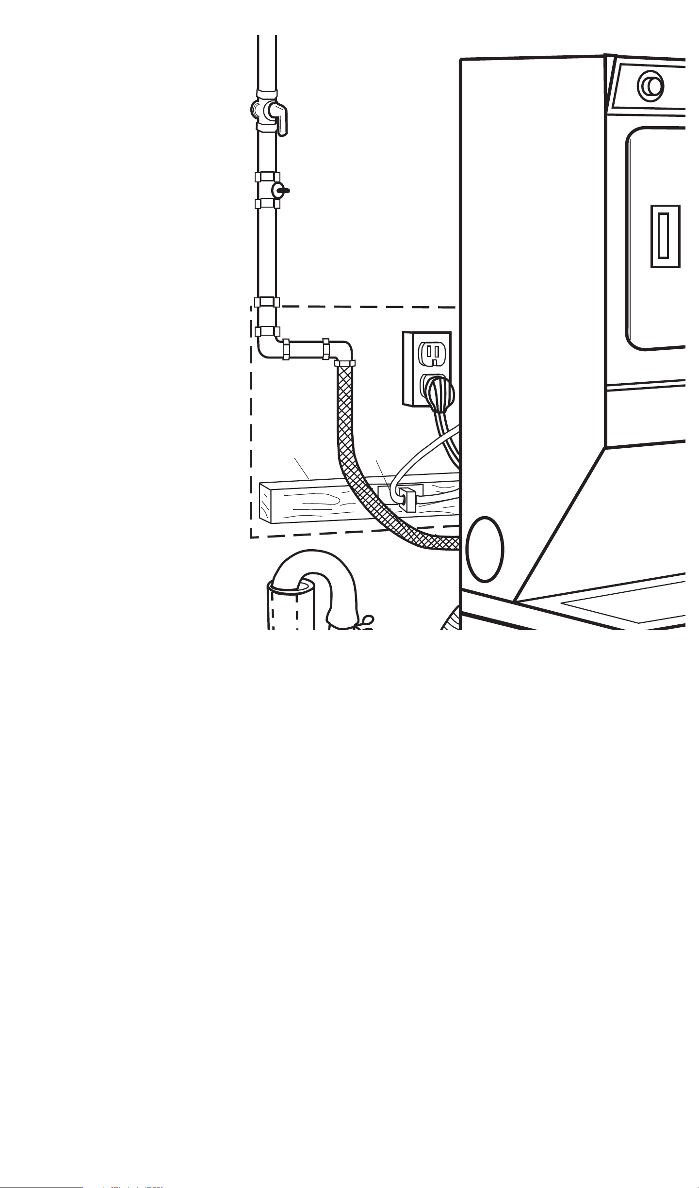
1" x 4" x 24"
mounting board
secured across
two wall studs or
on a concrete
wall.
Four screws
secure cable
bracket to
mounting
board.
The exhaust
requirements, cable
requirements and
wiring diagram are
located on the back
of the access panel.
Page 8
Panel G
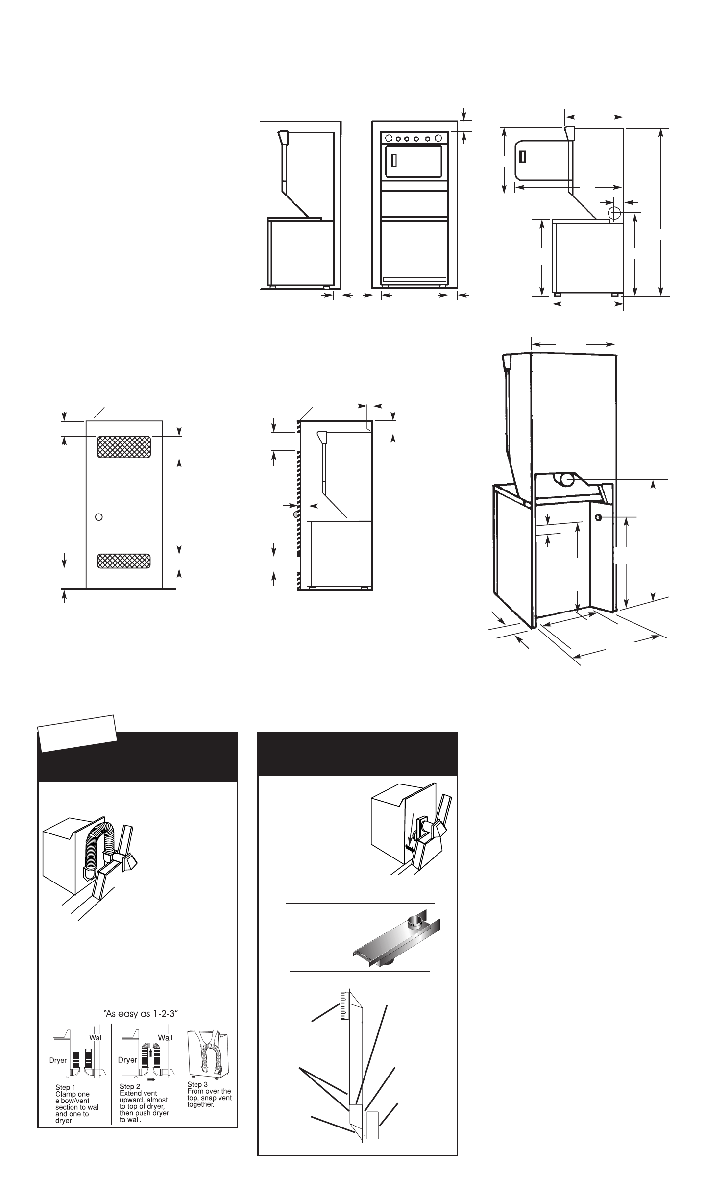
Recessed and closet installation instructions
This washer/dryer may be installed in a
recessed area or closet.
The installation spacing is in inches and
is minimum allowable. Additional
spacing should be considered for ease
of installation, servicing and compliance
with local codes and ordinances.
If closet door is installed, the minimum
unobstructed air openings in top and
bottom are required. Louvered doors
with equivalent air openings are
acceptable.
Note: No other fuel-burning appliance
may be installed in the same closet.
Other installations must use the minimum
dimensions indicated.
Product dimensions
Dryer
Washer
0" *
0"
*
Front View
6"
Recessed area minimum installation spacing
28"
48"
72-3/4"
5"
33-
1/4"
26-1/4"
32-1/4"
0" ***
Side View
27-3/8"
1-1/2"
hot
water
inlet
13-1/2"
recess
width
5"
recess
depth
28-1/2"
Drain
Exhaust
outlet
36-3/4"
27"
cold
water
inlet
34-3/4"
22-3/4"
Most installations will require at least 5 inch
clearance behind the dryer for the dryer
vent.
Location must be large enough to fully
open dryer door.
*Additional clearances for wall, door and floor moldings may be required or if external exhaust
elbow is used.
**Opening is minimum for closet door. Louvered door with equivalent air openings is acceptable.
***Additional space may be needed for exhaust elbow.
6"
0" ***
Closet installation must be exhausted outdoors.
closet door
48 sq. in. **
24 sq. in. **
1" min.
3"
3"
48 sq. in. **
front view
side view
closet door
24 sq. in. **
WARNING - To reduce the risk of fire, this appliance MUST BE EXHAUSTED OUTDOORS.
SURE CONNECTTMVent Kit
CRUSH
RESISTANT
Dura Safe
TM
Kits Make Installation Easy
◆Provides 4 1/2”
clearance between
dryer and wall
◆Snap-Lock fittings
◆Total kit length
8 feet
◆Additional vent can
be snapped between
sections for
longer runs
Kit Contains:
2- 4' vent sections with attached close elbows
1- Wall plate for close clearance installations
2- 4" clamps
Part #4396028
Sections separate,
fittings can face
same or opposite
Extra long
band-clamp
for dryer
connection
Swivel collar
Beveled edges
allow corner
installations
Telescoping
sections
Swivel collar
wall connection
◆ Provides 2 1/2” clearance
between dryer and wall
◆ Great for closet
installations
◆ 0"-18", 18”-29” or
29”- 50” periscopes
include one male
snap-lock fitting,
one extra long
draw-band collar
and one clamp
2
1/2 "
2 1/2"
Periscopes For Offset
Outlets, Tight Installations
◆ Use when vent outlets
overlap or are offset
◆ Excess length can
be trimmed to fit
18"-29" and 29"-50" Periscope
0"-18" Periscope
0"-18" : Part #4396037
18"-29" : Part #4396011
29"-50" : Part #4396014
Part #4396037
18"-29" : Part #4396011 29"-50" : Part #4396014
Dura Safe and Sure Connect are Trademarks of Whirlpool, U.S.A.
For more information,
or to easily place your
order, call
1-800-442-9991
To have your venting
professionally installed,
call
1-800-253-1301
for the nearest
authorized service
provider.
.
Page 9
Prepared by Whirlpool Corporation,
Benton Harbor, Michigan 49022
Part No. 3395326 Rev. F
© 2000 Whirlpool Corporation
® Registered Trademark of Whirlpool, U.S.A.
Printed in U.S.A.
 Loading...