

Page 1
Installation Instructions
Your safety and the safety of
others is very important.
We have provided many important
safety messages in this manual and
on your appliance. Always read and
obey all safety messages.
This is the safety alert
symbol. This symbol alerts
you to hazards that can kill
or hurt you and others. All safety
messages will be preceded by the
safety alert symbol and the word
“DANGER" or “WARNING”. These
words mean:
Adanger
You will be killed or seriously
injured if you don’t follow
instructions.
^WARNING
You can be killed or seriously
injured if you don’t follow
instructions.
All safety messages will identify the
hazard, tell you how to reduce the
chance of injury, and tell you what
can happen if the instructions are
not followed.
lMpooI
; COMMERCIAL
LAUNDRY
PRODUCTS
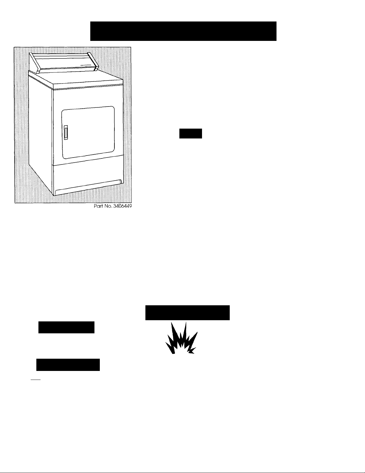
Commercial 27" Electronic Dryer
Gas
120-Volt 60-Hz 240-Volt 60-Hz
IMPORTANT:
Read and
save these
instructions.
Before you start...
Check locafion where dryer will be used.
Proper installation is your responsibility.
The dryer must not be installed or stored
in an area where it will be exposed to
water and/or weather. Make sure you
have everything necessary for correct
installation.
The dryer is equipped with an electronic
control timer, selector switches and
indicator lights. The timer is set to provide
45 minutes of drying time when
activated.
A WARNING
Explosion Hazard
Keep flammable materials and
vapors away from dryer.
Place dryer at least 18 inches
above the floor for a garage
installation.
Failure to do so can result in
death, explosion, fire, or burns.
It is the customer’s responsibility:
•To contact a qualified electrical
installer.
•To have dryers installed according to all
national and local codes and
ordinances.
Electric
Important:
Read these instructions before you start to
Save Instaliation instructions for iocal
Keep instaiiation instructions for future
instail the dryer.
eiectrical inspector's use.
reference.
Tools needed for installation:
adiustable wrench safety glasses
utility knife ievei
Phiilips screwdriver pliers
fiat-blade screwdriver duct tape
gloves
Parts supplied:
4 leveling legs
Parts owner must supply:
For electronic system support
(cards and additional electronic
features), contact:
IntelliCard Systems Ltd.
1520 Neptune Dr.
Boynton Beach, FL 33426
(407) 369-3435
a-9n
Page 2
Exhaust
requirements
^WARNING
Ü
Fire Hazard
Use a heavy metal vent.
Do not use a plastic vent.
Do not use a metal foil vent.
Failure to do so can result in
death or fire.
Do not use non-metal flexible vent,
metal vent that is smaller than tour
inches in diameter or exhaust hoods
with magnetic latches.
Do not exhaust dryer into a chimney,
furnace cold air vent, attic or crawl
space, or any other vent used for
venting.
Do not install flexible vent in enclosed
walls, ceilings or floors.
If using an existing exhaust system, clean
lint from entire length of exhaust system.
Make sure exhaust hood is not plugged
with lint.
The exhaust system should be inspected
and cleaned yearly.
Replace any vinyl or metallized plastic
foil exhaust vent with rigid metal or
flexible metal vent.
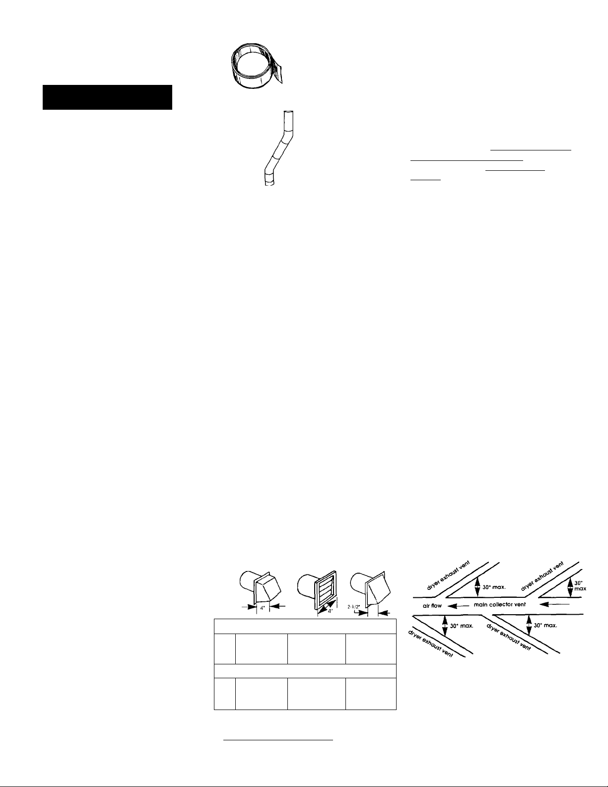
Use duct tape to
seal all joints.
exhaust airflow
better
exhaust
airflow
good
exhaust
airflow
Four-inch metal exhaust vent is required.
Plan installation to use the fewest
number of elbows and turns.
Metal flexible vent must be fully
extended and supported when the
dryer is in its final position. DO NOT
KINK OR CRUSH THE VENT. The metal
flexible vent must be completely
open to allow adequate exhaust air
to flow.
Allow as much room as possible
when using elbows or making turns,
Bend vent gradually to avoid kinking.
Remove excess flexible vent to avoid
sagging and kinking that may result in
reduced air flow.
Exhaust outlet is located at the
center of the bottom dryer back.
The exhaust vent can be routed up,
down, left, right, behind the dryer or
straight out the back of the dryer.
Kits are available to convert the
exhaust vent to be routed through
the cabinet right or left side or
through the bottom. See Page 3 for
Exhaust Kit part numbers. See Page
11 for product dimensions and
recessed area requirements.
Maximum length of exhaust system
depends upon the type of vent used,
number of elbows and type of
exhaust hood. The maximum length
for both rigid and flexible vent is
shown in the chart.
EXHAUST HOOD TYPE
available from your Whirlpool parts
distributor.
Service check: The back pressure in
any exhaust system must not exceed
0.6 inches of water column measured
with an inclined manometer at the
point that the exhaust vent connects
to the dryer.
Exhausting the electric dryer outside
is recommended. A closet installation
must be exhausted outside. Recessed
installation that is not exhausted
outside must use Exhaust Deflector,
Part No. 3391278 (electric dryer only),
available from your dealer.
If dryer is installed in a confined area,
such as a bedroom, bathroom or
closet, it must be exhausted to the
outside and provision made for
enough air for combustion and
ventilation. (Check governing codes
and ordinances.) See "Recessed
area and closet installation
instructions" on Page 11.
An exhaust hood should cap the
exhaust vent to prevent exhausted air
from returning into the dryer. The
outlet of the hood must be at least
12 inches from the ground or
anything else that may be in the path
of the exhaust.
Four-Inch outlet hood is preferred.
However, a 2-1 /2-inch outlet exhaust
hood may be used. A 2-1/2-inch
outlet creates greater back pressure
than other hood types. For
permanent installation, a stationary
exhaust system is required.
A main exhaust vent can be used for
exhausting a group of dryers. Main
exhaust vent should be sized to
remove 200 CFM of air per dryer.
Large-capacity lint screens ot proper
design may be used in the main
exhaust vent if checked and
cleaned frequently. The room where
the dryers are located should hove
make-up air equal to or greater than
the CFM of all the dryers in the room.
Page 2
No.
of 90°
turns
MUM LENGTH OF
MAX
0
2
MAXIMUM LENGTH OF 4-INCH DIAMETER FLEXIBLE METAL VENT
0
1
2
43 ft.
1 33 ft.
23 ft.
30 ft.
24 ft.
16 ft.
For exhaust systems not covered by
the exhaust length chart, see
Whirlpool Service Manual, "Exhausting
Whirlpool Dryers," Part No. 603197,
I-INCH DIAMETER RIGID METAL VENT
41 ft. 36 ft.
31 FT.
21 ft.
29 ft.
23 ft.
15 ft.
26 ft.
16 ft.
24 ft.
18 ft.
10 ft.
Back-draft Damper Kits, Part No
3391910, are available from your
Whirlpool dealer and should be
installed in each dryer's exhaust vent
to prevent exhausted air from
returning into the dryers and to keep
the exhaust in balance within the
main exhaust vent. Unobstructed air
openings are required.
Page 3
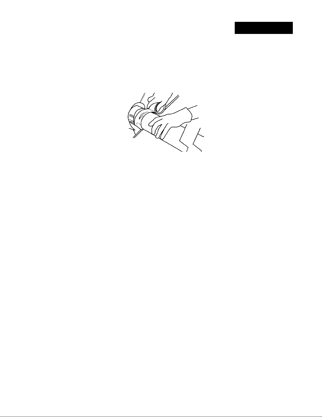
Each exhaust vent should enter the
main vent at an angle pointing in the
direction of the airflow. Vents entering
from the opposite side should be
staggered to reduce the exhausted
air from interfering with the other
vents.
The maximum angle of each vent
entering the main vent should be no
more than 30°.
Keep air openings free of dry
cleaning fluid fumes. Fumes create
acids which, when drawn through the
dryer heating units, can damage
dryers and loads being dried.
A ciean-out cover should be located
on the main exhaust vent for
periodically cleaning the exhaust
system.
An exhaust hood should cap the
outside end of the main vent to
prevent exhausted air from refurning
fo the dryers. If an exhausf hood
cannof be used, the outside end of
fhe main vent should have a sweep
elbow directed downward. If the
main vent travels vertically through
the roof, rather than through the wall,
install 180° sweep elbow on the end
of venf at least 2 feet above the
highest part of the building. The
opening wall or roof shall have a
diameter 1/2 inch larger than the
exhaust vent diameter. The exhaust
vent should be centered in the
opening.
exhaust
hood or
sweep
elbow \
2 ft. min. above
highest point of
building
main exhaust vent
wall
horizontal vent
-wall
180“
sweep
' elbow
- main collector vent
Exhaust vent connection
Determine which direction you need
to attach the exhaust vent to the
dryer. Next, determine the length of
the exhaust vent you will need to
connect the dryer to exhaust hood or
main vent.
To connect exhaust vent
straight out the back —
Attach exhaust vent to dryer vent.
Then connect exhaust vent to
exhaust hood or main exhaust vent.
Use duct tape to seal all joints.
This dryer may be converted to be
exhausted out the right or left side or
through the bottom. To convert the
dryer, one of fhe following kits MUST
be used:
Exhaust Kit No. 279818 (White)
Exhaust Kit No. 279819 (Almond)
Follow the instructions in the kit to
avoid operational and personal
hazard.
Gas Dryer
Gas supply
requirements
WARNING: If the
information in this manual
is not followed exactly, a
fire or explosion may result
causing property damage,
personal injury or death.
— Do not store or use
gasoline, or other
flammable vapors and
liquids in the vicinity of
this or any other
appliance.
— WHAT TO DO IF YOU SMELL
GAS:
• Do not try to light any
appliance.
• Do not touch any
electrical switch; Do not
use any phone in your
building.
• Immediately call your
gas supplier from a
neighbor's phone.
Follow gas supplier's
instructions.
• If you cannot reach your
gas supplier, call the fire
department.
— Installation and service
must be done by a
qualified installer, service
agency or the gas
supplier.
Do Not install screening or cap over
end of venf.
Observe all governing codes and
ordinances.
Post this warning in a prominent
location.
It is recommended that the operator
post, in a prominent location,
instructions for the customer's use in
the event fhe customer smells gas.
This information should be obtained
from your iocal gas supplier.
Page 3
Page 4
^WARNING
Ai/
Explosion Hazard
Connect dryer to a regulated
gas supply.
Use a new flexible gas supply
line.
If L.P. gas is used, the L.P. gas
supply must not exceed 13"
water column.
Failure to do so can result in
death, explosion, or fire.
This installation nnust conform
with American Nationai Standard,
Nationai Fuel Gas Code ANSI
Z223.1—latest edition (*, Page 5) and
all local codes and ordinances.
I The design of this dryer has
B.
been certified by the American Gas
Association for use at altitudes up to
10,000 feet above sea level at the
B.T.U. rating Indicated on the
model/serial rating plate. Burner input
adjustments are not required when
the dryer is operated up to this
elevation.
When installed above 10,000 feet, a
four percent (4%) reduction of the
burner B.T.U. rating shown on the
model/serial rating plate is required
for each 1,000 foot increase in
elevation. For assistance when
converting to other gas types and/or
installing above 10,000 feet elevation,
contact your local service company.
Check that the dryer is
equipped with the correct burner for
the particular type of gas used.
Burner information can be found on
the model/serial rating plate in the
door well of the appliance. If this
Information does not agree with the
type of gas available, see your
dealer,
■ This dryer is equipped for use
with NATURAL GAS. It is certified by
the American Gas Association for
manufactured, mixed and L.P
(propane and butane) gases with
appropriate conversion. No attempt
shall be made to convert the
appliance from the gas specified on
the model/serial rating plate for use
with a different gas without consulting
the serving gas supplier. Conversion
must be done by a qualified service
technician. Gas conversion kit part
numbers are listed on the gas valve
burner base.
C ■ Provide a rigid gas supply line
of 1/2-inch IPS pipe to the dryer
location. If the total length of the
supply line is more than 20 feet, larger
pipe will be needed. For L.P gas
usage, 3/8-inch, approved copper
tubing may be used. Pipe-joint
compounds suitable for use with L.P
gas should be used,
Fb If local codes and ordinances
permit, it is recommended that new,
flexible metal tubing, design-certified
by the American Gas Association, be
used for connecting the dryer to the
gas supply line. (The gas feed pipe,
which extends through the lower rear
of the dryer, is provided with 3/8-inch
male pipe thread.)
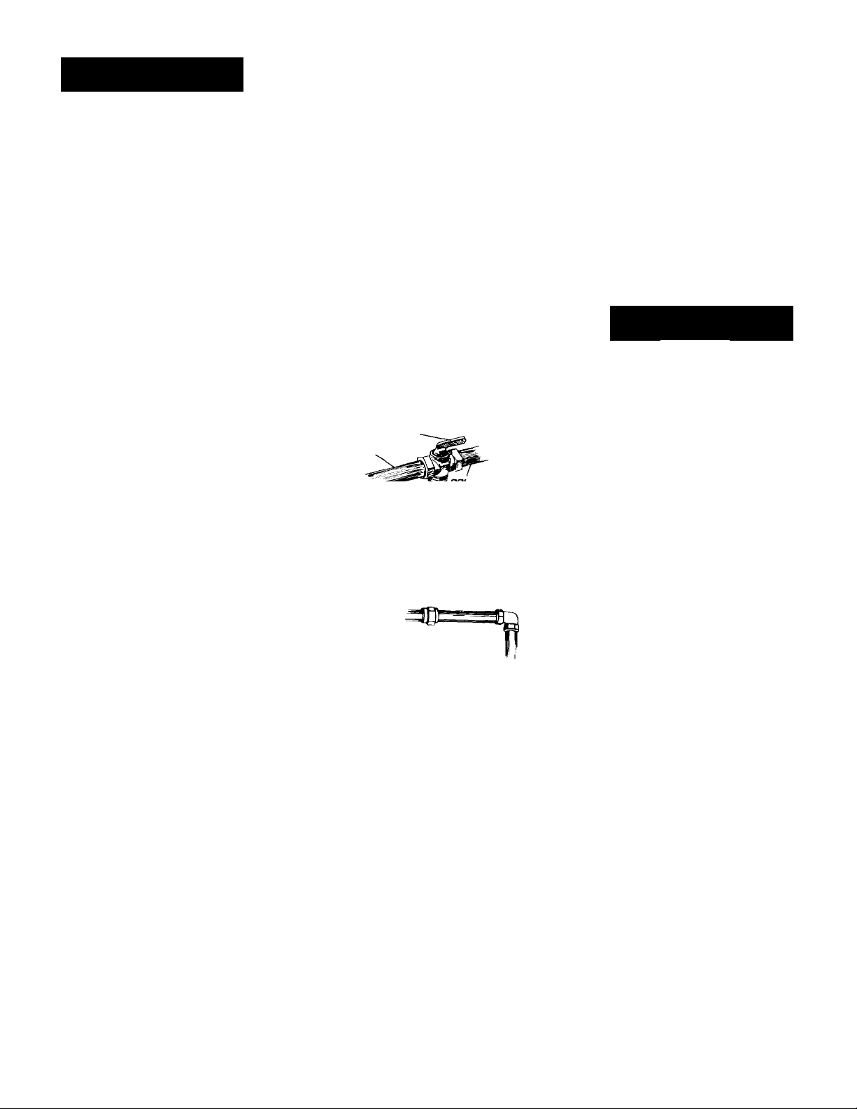
shutoff valve
“open" position
to dryer
supply line
BThe supply line shall be
equipped with a shutoff valve. This
valve should be located in the same
room as the dryer and should be in a
location that allows ease of opening
and closing. Do Not block access to
the shutoff valve.
H.
If rigid pipe is
used as a gas supply line, a
combination of pipe fittings
must be used to obtain an in-line
connection to the dryer.
IB Make sure that lower edges of the
cabinet, plus the back and bottom
sides of the dryer are free of
obstructions to permit adequate
clearance of air openings for
combustion air. See "Recessed area
and closet installation instructions," on
Page 11, for minimum spacing
requirements.
J B For ease of installation, operation
and servicing (if ever needed)
adequate space should be provided
around the dryer.
I A 1/8-inch, NPT plugged
K.
tapping, accessible for test gauge
connection, must be installed
immediately upstream of the gas
supply connector to the dryer.
The dryer and its individual shutoff
valve must be disconnected from the
gas supply piping system during any
pressure testing of that system at test
pressures in excess of 1 /2 psig
(3.4 kPa).
The dryer must be isolated from the
gas supply piping system by closing
the individual manual shutoff valve
during any pressure testing of the gas
supply piping system at test pressures
equal to or less than 1 /2 psig
(3,4 kPa).
Electrical
requirements
^WARNING
W
Electrical Shock Hazard
Plug into a grounded 3-prong
outlet.
Do not remove ground prong.
Do not use an adapter.
Do not use an extension cord.
Failure to follow these
instructions can result in
death, fire, or electrical shock.
If codes permit and a separate
ground wire is used, it is
recommended that a qualified
electrician determine that the ground
path is adequate.
Observe all governing codes and
ordinances.
A 120-volt, 60-Hz, AC-only, 15- or
20-ampere fused electrical supply is
required. A time-delay fuse or circuit
breaker is recommended. It is
recommended that a separate
circuit serving only this appliance be
provided.
Recommended ground
method
For your personal safety, this dryer
must be grounded. This dryer is
equipped with a power supply cord
having a 3-prong ground plug. To
minimize possible shock hazard, the
cord must be plugged into a mating
3-prong ground-type wall receptacle,
grounded in accordance with
National Electrical Code ANSI/NFPA
70 — latest edition (**, Page 5) and
all local codes and ordinances. If a
mating wall receptacle Is not
available, it is the personal
responsibility and obligation of the
Page 4
Page 5
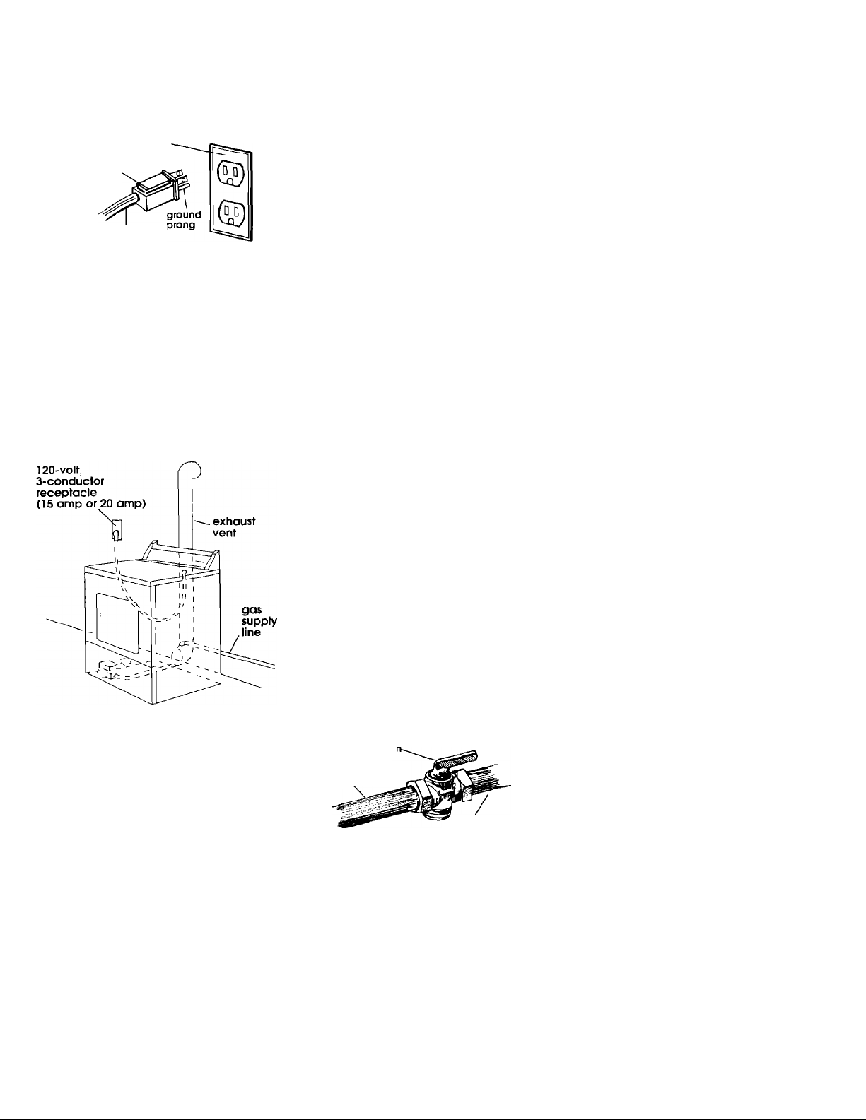
customer to have a properly
grounded, 3-prong wall receptacle
Installed by a qualified electrician. See
Figure 1.
3-prong,
ground-type
wall receptacle
3-prong,
ground
plug
power supply
cord
Figure 1
Copies of the standards listed above may
be obtained from:
‘American Gas Association
1515 Wilson Boulevard
Arlington, Virginia 22209
" National Fire Protection Association
Batterymarch Park
Quincy, Massachusetts 02269
Now start...
With dryer in laundry area.
fcB Take two of the cardboard
corners from the carton and place
them on the floor in back of the
dryer. Firmly grasp the body of the
dryer and gently lay it on its back on
the cardboard corners.
3 ■ With one of the legs in hand,
check the ridges for a diamond
marking. That's how far the leg is
supposed to go into the hole.
4 b Start to screw the leveling legs
into the holes by hand. (Use a small
amount of liquid detergent to
lubricate the screw threads so it is
easier to turn the legs.) Use a 1-inch
wrench or socket wrench to finish
turning the legs until you reach the
diamond mark.
Stand the dryer up.
Slide dryer onto cardboard or hardboard before moving across floor to
avoid damaging floor covering.
3 B Move dryer close to final
position. Remove cardboard or
hardboard from under dryer.
6 b Remove red cap from gas pipe.
Carefully move dryer into final
position. Place level on top of the
dryer, first side to side: then front to
back. If the dryer is not level, adjust
the legs of the dryer up or down until
the dryer is level.
7 B Connect gas supply to dryer. Use
pipe-joint compound resistant to the
action of L.Pgas for gas connections.
If flexible metal tubing is used, check
that there are no kinks.
9 b Use a brush and liquid detergent
to test all external gas connections
for leaks. Bubbles around connections
will indicate a leak. If a leak appears,
shut off gas valve controls and adjust
connections. Then check connections
NEVER TEST FOR GAS LEAKS
again.
WITH A FLAME. Close the access
panel.
All connections must be wrench-
tightened.
10
requirements," Pages 2-3. Connect
exhaust vent to exhaust hood. Use
duct tape to seal all joints in the
exhaust vent. Use caulking to seal
exterior wall opening around exhaust
hood.
grounded outlet.
START button to start dryer to remove
air from the gas supply line. Using a
full heat cycle (not the air cycle), let
the dryer run for at least five minutes.
If the burner does not ignite and you
can feel no heat inside the dryer, shut
off the dryer for five minutes. Check
that all gas supply valve controls are
in "ON" position and that the power
supply cord is plugged in. Repeat the
five-minute test.
I To exhaust dryer, see "Exhaust
.
11b Plug power supply cord into
12
Note: Dryer door must be closed for
dryer to operate. When door is open,
dryer stops, but timer continues to
run. To restart dryer, close door and
push START button.
Insert user card and push
.
I ■ Put on safety glasses and
gloves. Take tape off front corners of
dryer. Open dryer and remove the
literature and parts packages.
Remove the tape that holds the
drum to the cabinet. (Some dryer
drums are not taped for shipping.)
Move the drum by hand to make
certain all tape has been removed.
Wipe the interior of the drum
thoroughly with a damp cloth.
shutoff valve
"open" positioi
to dryer
gas supply line
6 b Open the shutoff valve in the
gas supply line.
Page 5
Page 6
Electric Dryer
Electrical
requirements
If codes permit and a separate
ground wire is used, it is
recommended that a qualified
electrician determine that the ground
path is adequate.
Important: Observe all governing
codes and ordinances.
A four-wire or three-wire, singie-phose,
120/240-volt, 60-Hz, AC-oniy electrical
supply (or four-wire or three-wire,
120/208-volt, if specified on the
model/serial rating plate) is required
on a separate, 30-ampere circuit,
fused on both sides of the line. A
time-delay fuse or circuit breaker is
recommended.The model/serial
rating plate is located in the door
well behind the dryer door on the
front of the opening.
A wiring diagram is located inside the
console or on back panel of dryer.
It is the personal responsibility and
obligation of the customer to contact
a qualified electrician to assure that
the electrical installation is adequate
and in conformance with the
National Electrical Code, ANSI/NFPA
70 — latest edition*, and all local
codes and ordinances.
Copies of the standards listed above may
be obtained from:
* National Fire Protection Association
Batterymarch Park
Quincy, Massachusetts 02269
Power supply cord
Use a new 30-amp power supply cord.
Local codes may permit the use of a
U.L.-listed, 120/240-volt minimum, 30ampere, dryer power supply cord kit
(pigtail). Power supply cord should be
Type SRD or SRDT and be at least four
feet long. The wires that connect to
the dryer must end with ring terminals
or spade terminals with upturned ends.
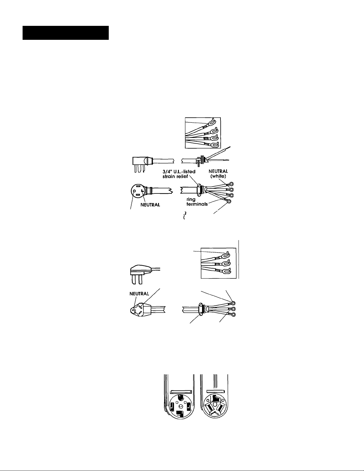
A 3/4", U.L.-listed strain relief must be
installed where the power supply cord
connects to the dryer (see Figures 2
and 3).
spade
terminals with
upturned ends
ground prong
Four-wire power supply cord
NEMA 14-30P
spade
terminals with
upturned ends
This blade connected
to this conductor.
round wire
green)
Figure 2
-------
ring
terminals
Four-wire installation is
recommended: The power supply
cord must have four. No.-10 copper
wires and match a tour-wire
receptacle of NEMAType 14-30R (see
Figure 4). The fourth wire (ground
conductor) must be identified with a
green cover and the neutral
conductor by a white cover.
Three-wire installation (if a four-wire
system is not available): The power
supply cord must have three, No.-lO
copper wires to match a three-wire
receptacle of NEMAType 10-30R (see
Figure 5).
Direct wire
The dryer can be connected directly
to fused disconnect or circuit breaker
box with four-wire or three-wire
flexible armored or non-metallic
sheathed copper cable (with ground
wire). Do Not use two-wire with bare
ground wire. All current-carrying wires
must be insulated.
A U.L.-listed conduit connector must
be installed at the junction box. USE
ONLY 10-GAUGE SOLID COPPER WIRE.
DO NOT USE ALUMINUM WIRE. Allow
four feet of slack in the line so dryer
can be moved if servicing is ever
necessary.
Page 6
Three-wire power supply cord
For use where
local codes
permit use of
flexible power
supply cord.
3/4" U.L.-listed
strain relief
NEMA 10-30P
Figure 3
four-wire
receptacle
(14- 30R)
Figure 4
NEUTRAL
(white or center)
three-wire
receptacle
(10-30R)
Figure 5
Page 7
Electrical
connection
A.
Four-wire
connection...
POWER SUPPLY CORD
^WARNING
w
Electrical Shock Hazard
Turn power supply off before
connecting cord.
Use a new 30 ampere power
supply cord.
Plug into a grounded outlet.
Failure to follow these
instructions can result in
death, fire, or electrical shock.
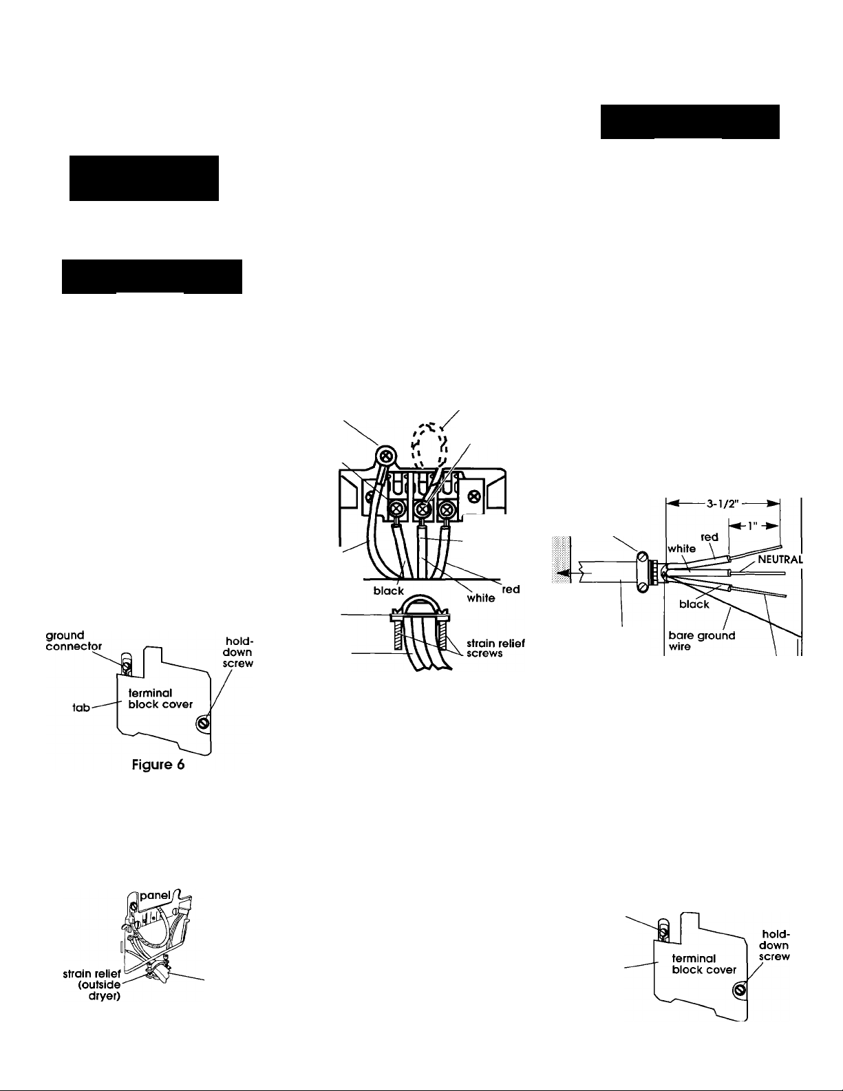
Turn power supply off.
1.
2a Remove hold-down screw and
terminal block cover.
external
^a Remove the center terminal
block screw. Remove the neutral
green with yellow stripe ground
wire from external ground
conductor screw. Connect neutral
green with yellow stripe ground
wire and the neutral wire (white or
center) of power supply cord
under the center screw of terminal
block.
Connect the other two insulated
wires under outer terminal block
screws.
Connect the green, ground wire
from fhe power supply cord to the
external ground conductor screw
(see Figure 8).
Tighten all terminal block screws
firmly.
external
ground
connector
ring
terminals
green-
wire from
power
supply
cord
strain
relief
power
supply
cord
green with yellow
stripes (attached
at factory)
Figure 8
center screw
(neutral)
center lead
must be
connected
to center
screw
DIRECT WIRE
^WARNING
>à
V
Electrical Shock Hazard
Turn power supply off before
connecting wires.
Use 10 gauge solid copper wire.
Electrically ground dryer.
Failure to follow these
instructions can result in death,
fire, or electrical shock.
1.
Turn power supply off.
2.
Strip 5 inches of outer covering
from end of cable. Cut 1-1/2 inches
off of the three insulated wires. Strip
1 inch of insulation from fhe end of
each insulated wire (see Figure 9).
3/4"
U.L.-listed
strain relief
j
to
disconnect
box
10-gauge,
3-wire with
ground wire
(Romex)
wire stripped
of insulation
-5"
3 a Attach 3/4" U.L.-llsted strain relief
(U.L. nnarklng on strain relief) fo the
hole below terminal box opening (see
Figure 7). Tighten strain relief firmly to
cabinet so it is in a hori zontal position,
Place power supply cord through the
strain relief
rear
Figure 7
power
supply
cord
5a Tighten strain relief screws.
Oa Insert tab of terminal block
cover into slot of the dryer rear
panel (see Figure 6). Secure cover
with hold-down screw.
Figure 9
U-shaped hook
\ * Shape the end of each
wire into a "U" shaped hook
(see Figure 10). The bare
wire must be 4-1/2" long
after forming the hook.
Figure 10
3a Remove hold-down screw and
terminal block cover.
external
ground
connector
tab
Figure 11
Page 7
Page 8
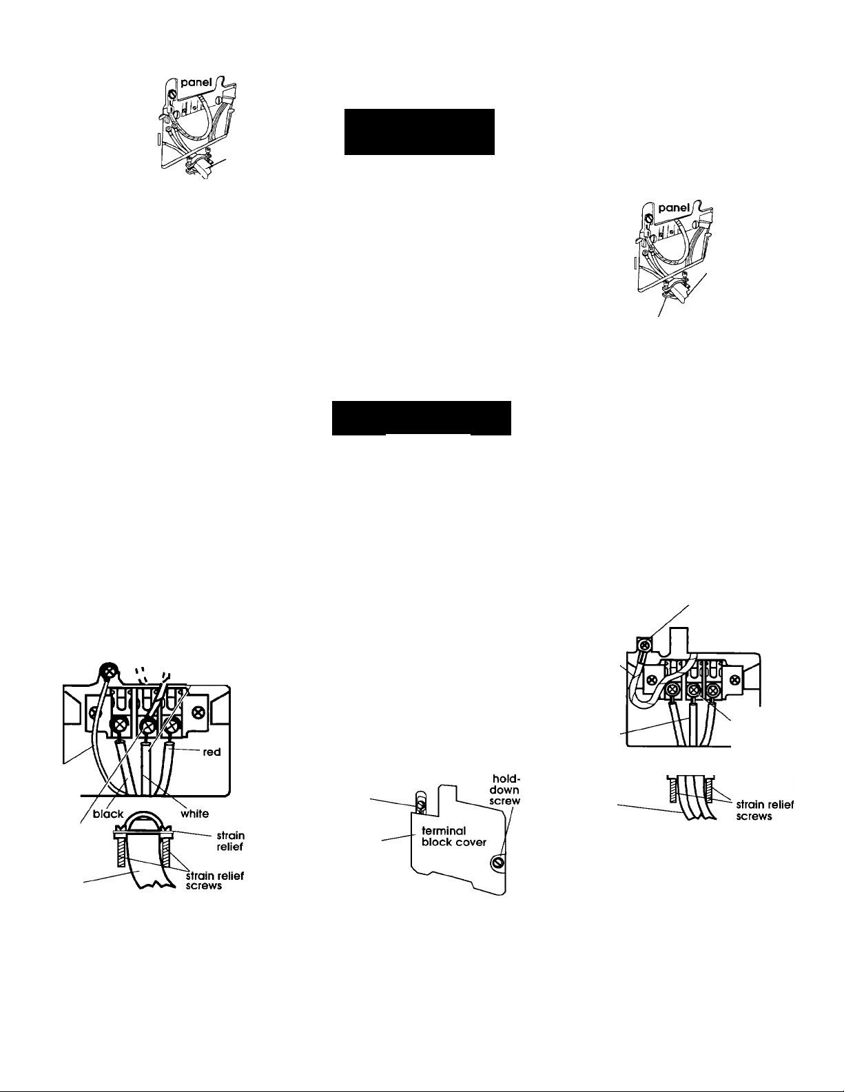
Attach 3/4" U.L-
rear
listed strain relief (U.L.
marking on strain
relieO to the hole
below terminal box
opening (see Figure
12). Tighten strain
relief firmly to cabinet
so it is in a horizontal
position. Place direct
wire cable through
the strain relief.
Strom relief
(outside dryer)
Figure 12
power
supply
cable
Remove the center terminal
block screw, Remove the neutral
green with yellow stripe ground wire
from external ground conductor
screw. Connect neutral green with
yellow stripe ground wire and the
neutral wire (white or center) of
direct wire cable under the center
screw of terminal block. Place the
hook-shaped end of the wire over
the terminal block screw with open
side of the hook facing to the right.
Squeeze hook end of wire together
to form a loop.
Connect the other two insulated
wires under outer terminal block
screws. Attach wires using the same
method as the neutral wire.
Connect the direct wire cable (bare)
ground wire to the external ground
conductor screw (see Figure 13).
Tighten all terminal block screws
firmly.
neutral green with yellow
external factory)
ground center lead
connector \ must be
stripes (attached at
^ '1 to center
^ u screw
connected
/
bare wire
from cable
center
screw
(neutral)
B.
Three-wire
connection...
Where local codes permit
connecting frame-ground
conductor to the neutral wire:
This dryer is manufactured with the
frame-ground conductor connected
to the NEUTRAL (center) of the wiring
harness at the terminal block. If local
codes do Not permit this type of
connection, use “Four-wire
connection” instructions.
POWER SUPPLY CORD
^WARNING
V
Electrical Shock Hazard
Turn power supply off before
connecting cord.
Use a new 30 ampere power
supply cord.
Plug into a grounded outlet.
Failure to follow these
instructions can result in
death, fire, or electrical shock.
la
Turn power supply off.
^ a Remove hold-down screw and
terminal block cover.
external ground
connector
tab
3a Attach 3/4" U.L.-listed strain
relief (U.L. marking on strain relief)
to the hole below terminal box
opening (see Figure 15). Tighten
strain relief firmly to cabinet so it is
in a horizontal position. Place
power supply cord through strain
relief.
rear
power
supply
cord
strain relief
(outside dryer)
Figure 15
*Fa Loosen or remove terminal
block screws. Connect the neutral
wire (white or center) of power
supply cord under the center screw
of the terminal block.
Connect the other two wires to
outer terminal block screws (see
Figure 16).
Tighten all terminal block screws
firmly.
Center wire MUST be connected to
center screw.
green with
yellow stripes
(attached at
factory)
neutral
strain
relief
power
supply cord
external ground
connector
Figure 16
center
screw
(neutral)
power
supply cable
Figure 13
0a Tighten strain relief screws.
7 a Insert tab of terminal block
cover into slot of the dryer rear
panel (see Figure 11). Secure cover
with hold-down screw.
Page 8
0a Tighten strain relief screws.
Figure 14
Oa Insert tab of terminal block
cover into slot of the dryer rear
panel (see Figure 14). Secure cover
with hold-down screw.
Page 9
DIRECT WIRE
^WARNING
W
Electrical Shock Hazard
Turn power supply off before
connecting wires.
Use 10 gauge solid copper wire.
Electrically ground dryer.
Failure to follow these
instructions can result in death,
fire, or electrical shock.
1.
Turn power supply off.
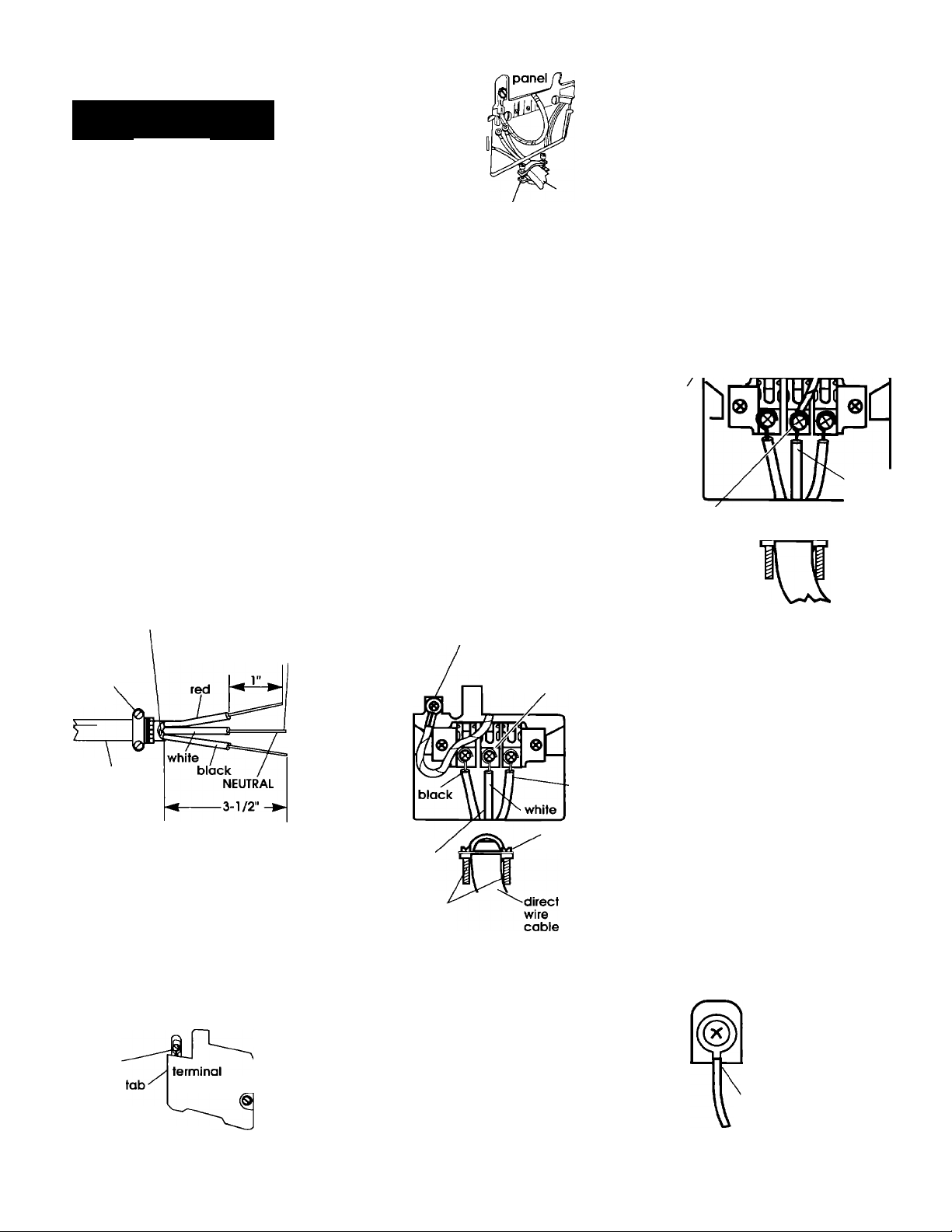
fcB Strip 3-1/2 inches of outer
covering from end of cabie. If using
three-wire cable with ground wire,
cut the bare wire even with outer
covering. Strip 1 inch of insulation
from the end of each insulated wire
(see Figure 17).
Bare wire cut short. Wire is not
used. Dryer is grounded
through direct wire cable.
3/4"
U.L.-listed
strain relief
to disconnect
box
wire stripped
of insulation
4b Attach 3/4" U.L.-
rear
listed strain relief
(U.L. marking on
strain relieO to the
hole below terminal
box opening (see
Figure 20). Tighten
strain relief firmly to
cabinet so it is in a
horizontal position.
Place direct wire
cable through strain
strain relief
(outside dryer)
Figure 20
relief.
Ob Loosen or remove terminal
block screws. Connect the neutral
wire (white or center) of direct wire
cable under the center screw of
the terminal block. Place the hook
shaped end of the wire over the
terminal block screw with open side
of the hook facing to the right.
Squeeze hook end of wire together
to form a loop.
Connect the other two wires under
the outer terminal block screws.
Attach wires using the same
method as the neutral wire (see
Figure 21).
Tighten all terminal block screws
firmly.
Center wire MUST be connected to
center screw.
green with
yellow
stripes
(attached
at factory)
external ground
' connector
(neutral)
center
screw
Power Supply Cord
or Direct Wire
Where local codes DO NOT
permit connecting the frameground conductor to the
neutral (white) wire:
1 a. Turn power supply off.
2a. Complete Power Supply Cord
Steps 2-3, Page 7 or Direct Wire Steps
2-4, Pages 7-8.
external ground
connector
separate
copper
ground
wire
grounded
to a metal
cold water
pipe.
center screw
(neutral)
Figure 22
3a. Remove the neutral ground wire
(green/yellow striped wire) from
external ground connector screw.
Remove center terminal block screw
and fasten neutral ground wire to
screw (see Figure 22).
neutral ground
wire
(green/yellow
striped wire)
V
.center lead
must be
connected
to center
screw
i 0-gauge
3-wire or,
10-gauge,
3-wire with
ground wire
(Romex)
Direct wire preparation
s Figure 17
Shape the end of
each wire into a
u-shaped
hook
Figure 18
"U" shaped hook
(see Figure 18).
3 b Remove hold-down screw and
terminal block cover.
external
ground
connector
block cover / scfew
Figure 19
hold-
/down
center lead
must be
connected
to center
screw
strain
relief
Figure 21
6b Tighten strain relief screws.
# B Insert tab of terminal block
cover into slot of the dryer rear
panel (See Figure 19). Secure
cover with hold-down screw.
strain
relief
red
4a. Complete Power Supply Cord
Steps 4-6, Page 7, or Direct Wire Steps
5-7, Page 8.
5a. After reattaching the terminal
block cover, connect separate
copper ground wire from external
ground connector to grounded
metal cold water pipe. Contact a
qualified electrician to assure that
ground path is adequate (see Figure
23).
terminal
block cover
separate copper ground
wire connected and
grounded to a grounded,
metal, cold water pipe
Figure 23
Page 9
Page 10
Now start...
With dryer in laundry area...
t «Put on safety glasses and gloves.
Take tape off front corners of dryer.
2»Open dryer and rennove
literature and parts packages.
Remove parts from packages.
Check that all parts were Included.
3» Remove the tape that holds the
drum to the cabinet. (Some dryer
drums are not taped for shipping.)
Move the drum by hand to make sure
all tape has been removed. Wipe the
interior of the drum thoroughly with a
damp cloth. Remove tape from the
lint screen.
O»Firmly grasp the body of the
dryer and gently lay it on its back on
the cardboard corners.
6 »With one of the legs in hand,
check the ridges for a diamond
marking. That's how far the leg is
supposed to go into the hole.
7 »Start to screw the leveling legs
into the holes by hand. (Use a small
amount of liquid detergent to
lubricate the screw threads so it is
easier to turn the legs.) Use a 1 -inch
wrench or socket wrench to finish
turning the legs until you reach the
diamond mark.
Stand the dryer up.
8.
Slide dryer onto cardboard or hard-
board before moving across floor to
avoid damaging floor covering.
9»Move dryer close to final
position. Remove cardboard or
hardboard from under dryer.
I Carefully move dryer into final
10.
position. Place level on top of the
dryer, first side to side; then front to
back. If the dryer is not level, adjust
the legs of the dryer up or down until
the dryer is level.
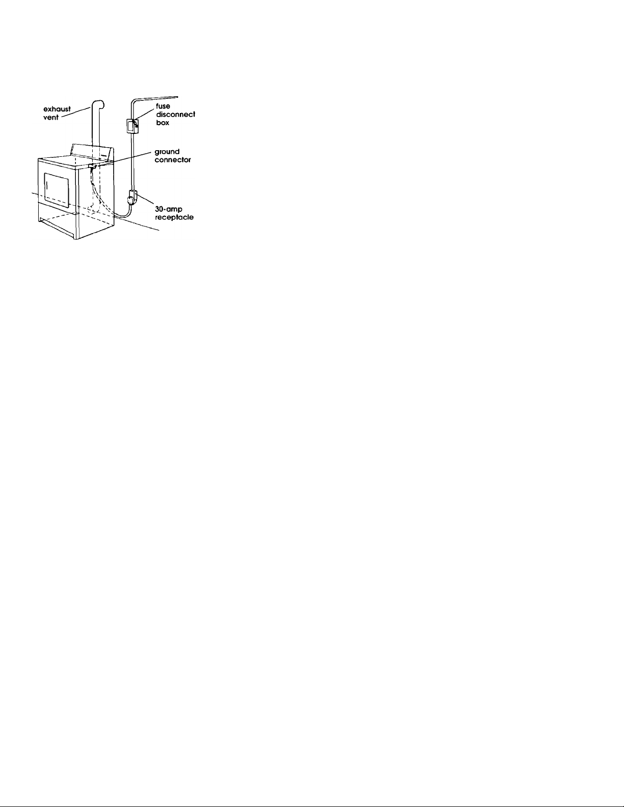
1 1 »To exhaust dryer, see "Exhaust
requirements," Pages 2-3. Connect
exhaust vent to exhaust hood. Use
duct tape to seal all joints in the
exhaust vent. Use caulking to seal
exterior wall opening around exhaust
hood.
I Plug power supply cord into
12
.
grounded outlet or connect power
supply cable.
I Insert user card and push
13,
START button. Using a full heat cycle
(not the air cycle), let the dryer run
for at least five minutes. Open dryer
and check that there is heat.
Note: Dryer door must be closed for
dryer to operate. When door is open,
dryer stops, but timer continues to
run. To restart dryer, close door and
push START button.
4 «Take two of the cardboard
corners from the carton and place
them on the floor in back of the dryer.
Page 10
Page 11
Recessed area and
closet installation
instructions
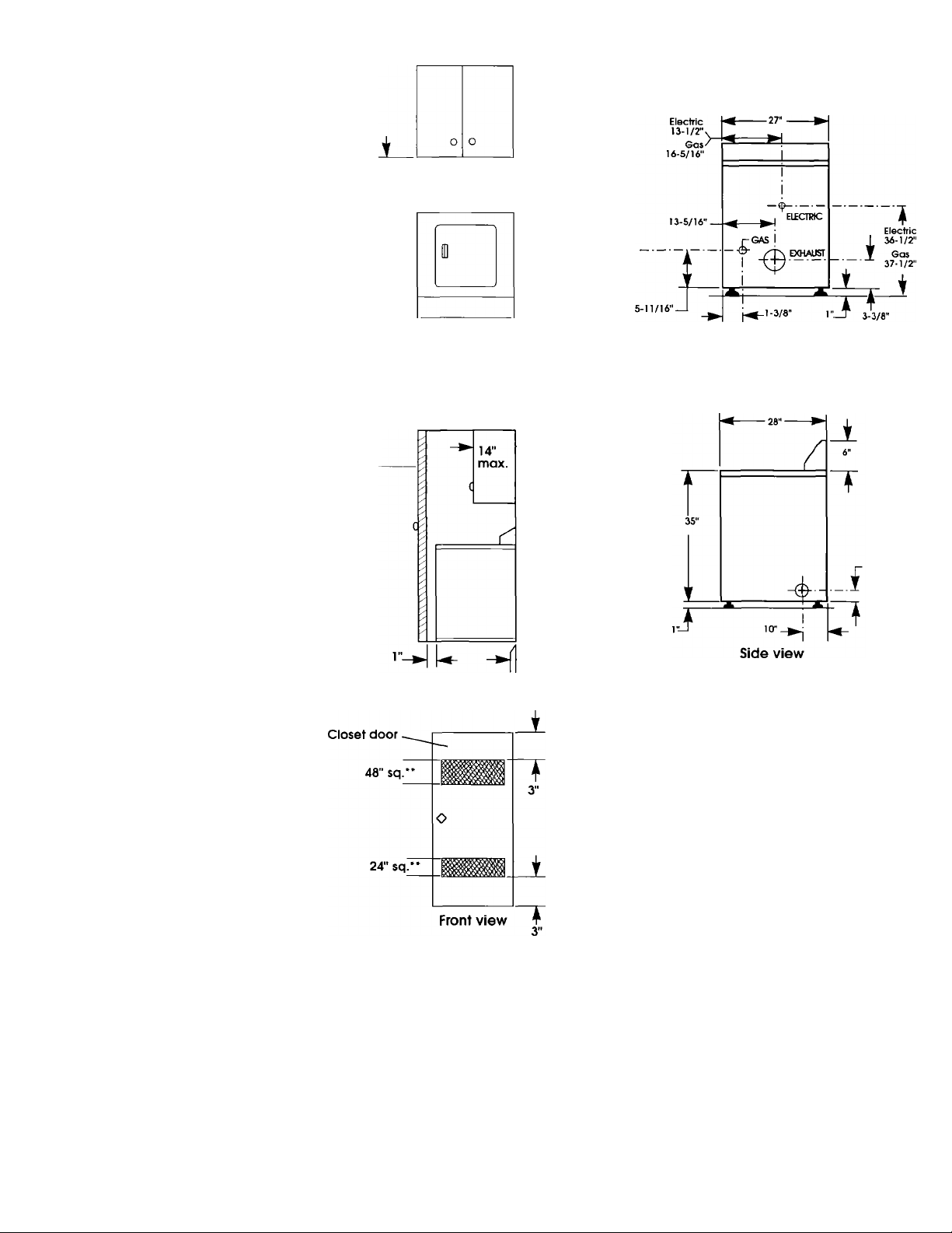
This dryer rriay be installed in a
recessed area or cioset.
The installation spacing is the
minimum allowable. Additional
spacing should be considered for
ease of installation, servicing and
compliance with local codes and
ordinances.
If closet door is installed, the minimum
unobstructed air openings in the top
and bottom are required. Door must
have two centered openings as
illustrated. Both openings must
provide a minimum of 72 square
inches of unobstructed airflow as
shown. Louvered doors with
equivalent air openings are
acceptable.
Companion appliance spacing
shouid be considered.
For cioset installation, to prevent iarge
amounts of iint and moisture from
accumuiating, to maintain drying
efficiency, and to prevent exposure to
possibie health hazards, dryers must
be exhausted outdoors.
Recessed non-exhausted installation
must use only the rear exhaust
position, and Exhaust Deflector Kit,
Part No. 3391278 (electric dryer only),
is required.
Shelf or cabinet is not permitted
above dryer when non-exhausted.
No other fuel-burning appiiance may
be installed in the same cioset.
Detailed space requirements for
recessed area and closet installations
can be found on the label on the
back panel of the dryer.
Closet
door
0"*_
Product dimensions
15"
Back view
Recessed
front view
. 3-3/8"
.0"*
Side view
* Additionoi clearances for wall, door
and floor moldings may be required or
if externai exhaust elbow is used.
■ Opening is minimum for cioset door.
Louvered door with equivalent air
opening is acceptable.
Page 11
Page 12

Moving the dryer
If dryer does not
If you need
to a new location...
Slide dryer onto cardboard or
hardboard before moving across floor
to avoid damaging floor covering.
Gas dryer models:
• Disconnect power supply cord.
Tape securely to dryer.
• Shut off the gas supply valve in the
gas supply line.
• Disconnect gas pipe and fittings
from dryer and cap gas supply line.
Tape end of dryer gas pipe.
Before installing gas dryer in a new
location, check with your gas supplier
or dealer to see that your dryer is
equipped with the correct burner for
the particular type of gas in your new
building. Burner information may be
found on the rating plate in the door
well of the dryer.
Electric dryer models:
• Shut off electrical supply to dryer.
• Disconnect the power supply cord
or cable from the dryer terminal
block.
All models:
• Make sure leveling legs are secure
in dryer base.
• Tape drum to front panel.
• Tape dryer door and lint screen.
operate...
Check the tollov^ring to be sure that:
1. Electrical supply is connected.
2. Circuit breakers are not tripped or
house fuses blown.
3. Door is closed.
4. User card has been inserted.
5. START button has been pushed.
6. For gas dryers, check that gas
supply line shutoff valve is set in
open position.
assistance...
The Whirlpool Consumer Assistance
Center will answer any questions
about operating or maintaining your
dryers not covered in the Installation
Instructions. The Whirlpool Consumer
Assistance Center is open 24 hours a
day, 7 days a week. Just dial l-(800)-
253-1301 —the call is free.
When you call, you will need the
dryer model number and serial
number. Both numbers can be found
on the model/serial rating plate
located in the door well behind the
dryer door and on the front of
opening.
Part No. 3406449
© 1997 Whirlpool Corporation
'WhMpwl
/ CORPORATION
Prepared by Whirlpool Corporation, Benton Harbor, Michigan 49022
Printed in U.S.A.
 Loading...