

Page 1

PARTS &
SERVICE Manual
AUTO SPARKLE
SAP MODEL NO DESCRIPTION
3775
AUTOSPARKLE-110V,APWH.W.PUMP(BARBA,CURAC
Page 2

CONTENTS
S No DESCRIPTION PAGE No
1 SPECIFICATIONS 3
2. AUTOSPRAKLE FEATURES 6
3. CONTROL & FUNCTIONS 6
4. WIRING DIAGRAM 10
5. PROGRAM TIMING 12
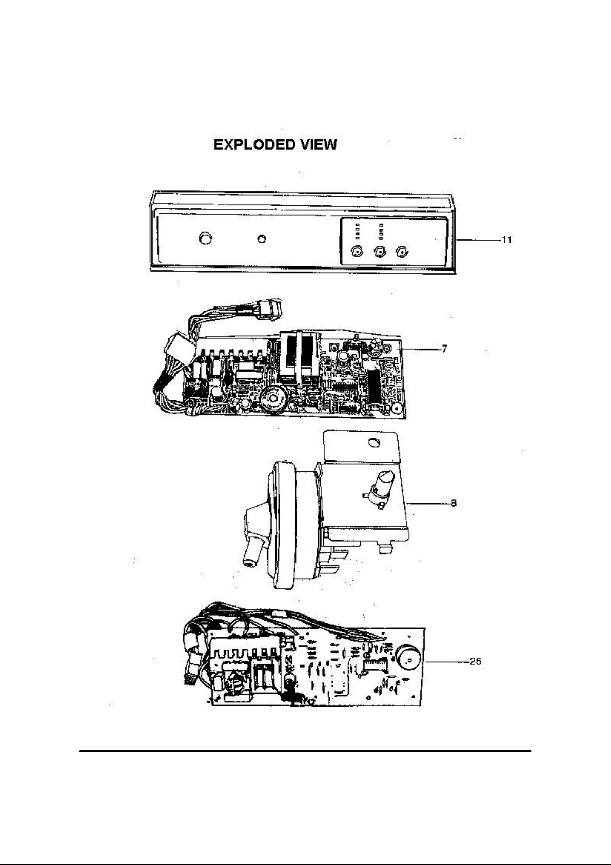
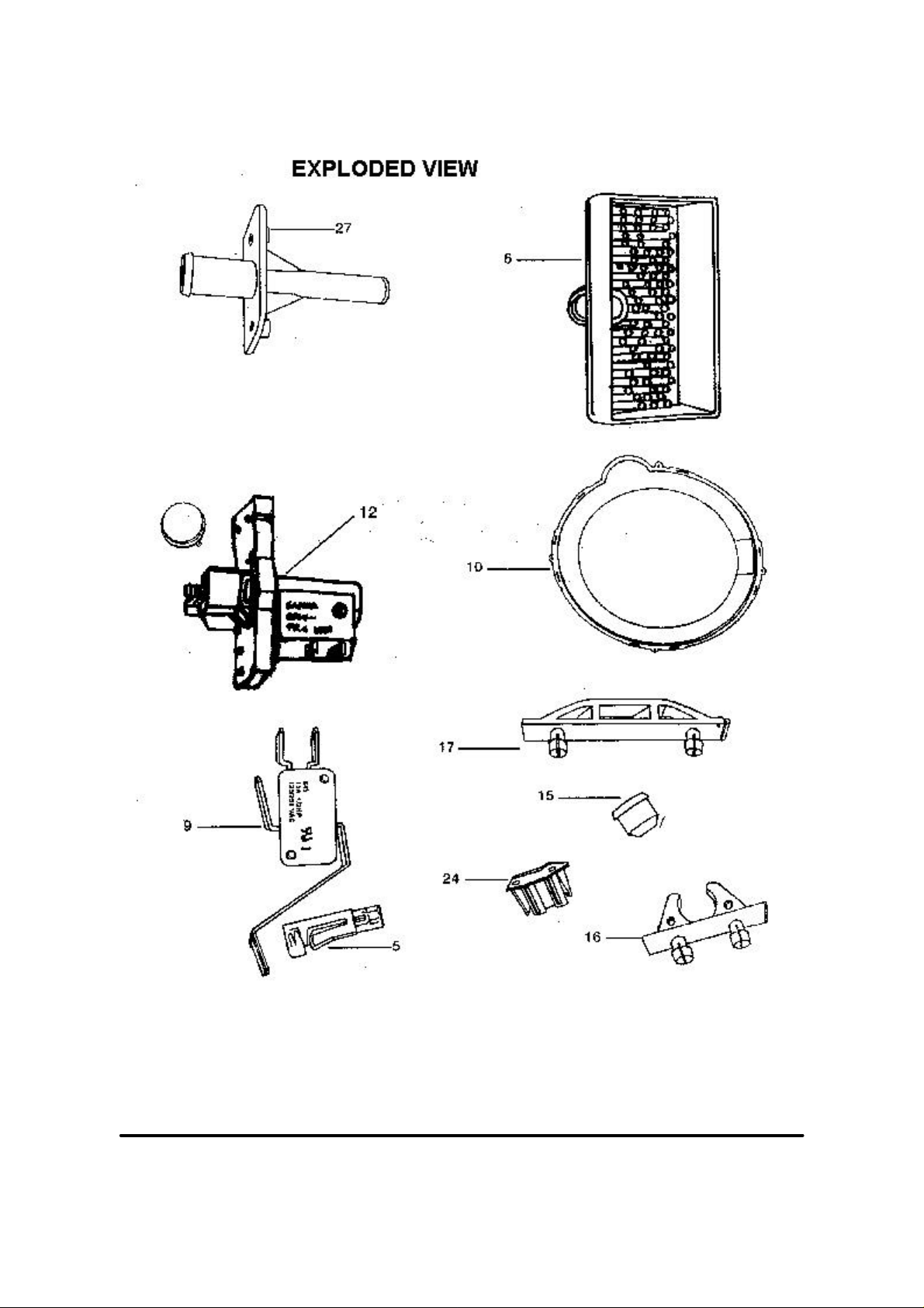
6. EXPLODED VIEWS 15
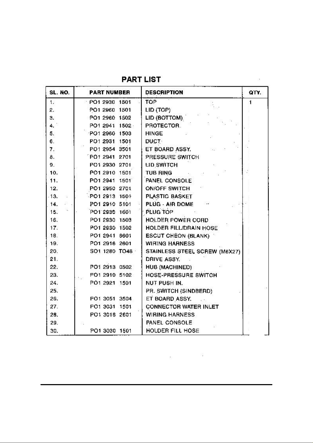
7. PARTS LIST 18
8. FAULT FINDING-GUIDE 20
This document is only intended for qualified technicians who are aware of the respective safety regulations.
Revised on 07/01/2003 Subject to modification
Document No. WOI/WM/2003/001
Page 3

Specifications
1 .Model Description AUTOSPARKLE
2. Machine Type Top Loading fully Automatic Agitator wash
3. Capacity 5 Kg.
4. M/c Wt. 38 Kg.
5. M/c Dimension 570 mm (W) x 590 mm (B) x 1000 mm (H)
6. Cabinet Finish Pre painted Steel
7. No of programs 1 9
8. Program Select 4 LED’s - Normal, Speed, Heavy & delicate (Heavy double rinse)
9. Start/Pause Provided
10. Error Signal (Audio) Available
I 1. Wash Action Normal, Speedy, Heavy (65 SPM) Delicate (45 SPM)
12. Spin Speed 740 RPM (Max.)
13.Dispenser Bleach dispenser (Hose less type)
Blue dispensing (through Dispenser fitted to Agitator.
1 4. Lint filter Available (fitted to blue dispenser)
15. Motor 1/4 HP, 1400 RPM, PSC Type, single speed (input 575W)
16. Operating Voltage 110V 50Hz
17. Basket Polypropylene
18. Temp Permitted Max. 50"C
19. Water level switch Rotary continuous (4 indications Extra Low, Low, Medium, High)
20. Water volume (liters) Setting With Load W/o Load
Extra Low 25 27
Medium 50 54
High 65 70
Low 35 38
21. Water Saver By selection
This document is only intended for qualified technicians who are aware of the respective safety regulations.
Revised on 07/01/2003 Subject to modification
Document No. WOI/WM/2003/001
Page 4

This document is only intended for qualified technicians who are aware of the respective safety regulations.
Revised on 07/01/2003 Subject to modification
Document No. WOI/WM/2003/001
Page 5

AUTOSPARKLE - FEATURES :
? Spin Basket - P.P. Material
? Easy spin basket removal is possible
? Hose less bleach inlet system
? Single Pressure switch hose.
? LID switch control for Agitate/Spin operations.
(8 Bit controller)
? Tub ring mounting with out screws
A LOOK AT THE CONTROL PANEL...
The following are the knobs/switches available at the panel
1 Power ON/OFF Switch
2. Water level selector
3. Course Select
4. Program Select
5. Start/Pause Button
In addition to the above, 2 sets of 4 each LED indications are also provided to indicate the status of operations. Please refer
the annexure for schematic view of the Panel. POWER ON/OFF SWITCH
This document is only intended for qualified technicians who are aware of the respective safety regulations.
Revised on 07/01/2003 Subject to modification
Document No. WOI/WM/2003/001
Page 6

This switch is basically a ON/OFF switch controlling the supply to the machine, by pressing this switch, the machine is
turned ON.
To Switch off the machine, press the switch again.
Machine operation stops automatically at the end of the cycle and this switch will still
remain in ON position Similar To ALPHA model and the user has to switch it OFF before removing the clothes from the
spin basket.
WATER LEVEL SELECTOR
This is similar to our existing Load Selector with the difference that the pressure switch mounted inside is "Constant Reset
Type".
PROGRAM SELECT BUTTON
This feature enables the user to select the various wash cycles viz., NORMAL, SPEEDY, DELICATE and HEAVY. The
selection is effected by pressing this Program Select and indicate by the glowing of the corresponding LED indicator in the
panel. The default setting is NORMAL cycle. Other cycles can be selected by pressing the Program Select button in the
following sequence.
CONTROL SETTING PROGRAM ACTIVATED
POWER SWITCH ON(Default) NORMAL
FIRST PRESS SPEEDY
SECOND PRESS DELICATE
THIRD PRESS HEAVY
If the user presses for the fourth time, the machine returns to default setting i.e., NORMAL cycle.
This document is only intended for qualified technicians who are aware of the respective safety regulations.
Revised on 07/01/2003 Subject to modification
Document No. WOI/WM/2003/001
Page 7

COURSE SELECT
This feature enables the user to select the various combination of SOAK, WASH, RINSE and SPIN. The Selection is
effected by pressing this Course Select button and indicated by the glowing of the corresponding LED indicator in the
panel. The default setting is WASH, RINSE and SPIN i.e. whenever the Power Switch is switched ON, these 3 processes
will be selected by default and the corresponding LED lamps will glow. As the Course Select button is pressed further, the
other selections can be made in the following sequence:
COURSE SELECT PROGRAM
Power Switch ON(Default)
First Press
Second Press
Third Press
Fourth Press
Fifth Press
If the user presses for the sixth time, the machine returns to default setting i.e., WASH, RINSE and SPIN cycle. Whenever
Speedy Program is selected, the course is selected by default, as WASH, RINSE and SPIN and hence no other
combinations are possible.
START/PAUSE BUTTON
This button is used to start or pause the cycle. Once all the settings are set, the user has to press this button to commence
the cycle. Similarly, this button can also be pressed while the machine is operating to pause the operation. This facility may
be used in case the Customer wants to add some more detergent or clothes in the middle of the cycle. Whenever the
operation is paused, the user will get a continuous beep sound to indicate that the machine has been 'paused'. To restart the
cycle, the button has to be pressed again.
LED INDICATORS
This is 2 sets of 4 each LED indicators provided in the control panel. This helps to indicate the status of the cycle in
progress.
SOAK WASH RINSE SPIN
WASH RINSE SPIN
WASH
WASH RINSE
RINSE SPIN
SPIN
WASH PROGAMME
From the above details on the various controls available in this model, it is clear that the user can choose the combination
of various course (SOAK, WASH, RINSE, and SPIN) and Programmer (NORMAL, SPEEDY, DELICATE, and
HEAVY). The possible combinations for say a NORMAL cycle are
1. WASH RINSE & SPIN
2. SOAK WASH RINSE &SPIN
3. WASH ONLY
4. WASH AND RINSE
5. RINSE AND SPIN
6. SPIN ONLY
Thus each of NORMAL, DELICATE & HEAVY cycle can give 6 possible combinations resulting in 18 cycles. In case of
SPEEDY cycle, the course options are preset as WASH, RINSE and SPIN and hence no other combinations can be chosen.
Thus, a total combination of 18 plus 1 SPEEDY cycle i.e. a total of 19 cycles is possible in this model.
This document is only intended for qualified technicians who are aware of the respective safety regulations.
Revised on 07/01/2003 Subject to modification
Document No. WOI/WM/2003/001
Page 8

The timing sequences of this individual cycle are enclosed for your ready reference.
OPERATING INSTRUCTIONS:
1. Add detergent and load the clothes as usual.
2. Connect the Fill Hose and Power cord to the appropriate points. 3. Place the Drain Hose on the ground.
4. Switch on the machine. Set the Water level and Water inlet Selector (as applicable) to the desired settings.
5. Select the appropriate Course and Program.
6. Press the Start button to commence the operation.
7. At the completion of the cycle, the user will get a intermittent beep sound lasting for 20 seconds. STATUS
INDICATORS
As you are aware, LED indicators are provided in the Control Panel to indicate the status of the wash cycle. Whenever the
Program and Course is selected, the corresponding LED indicators will glow. Once the operation is commenced, the LED
corresponding to the first operation (Soak or Wash or Rinse or Spin) will blink indicating that the particular process is on.
Once the process is completed, the corresponding LED will go off and the LED corresponding to the next operation will
start blinking. Thus by a look at the Control Panel, the user can come to know of the process in progress (indicated by the
blinking LED) and the pending processes for the completion (indicated by glowing LED/s) of the cycle. Let us take an
example of a cycle wherein WASH, RINSE & SPIN is selected. The sequence of LED display will be as follows:
1.At the time of setting 2.During Washing 3.At the time of setting 4.During Washing
OFF SOAK
ON WASH
ON RINSE
ON SPIN
OFF SOAK
BLINK WASH
ON RINSE
ON RINSE
OFF SOAK
ON WASH
BLINK RINSE
ON SPIN
OFF SOAK
OFF WASH
OFF SPIN
BLINK SPIN
SPECIAL FEATURES IN ET MODES:
• DOUBLE RINSE FACILITY IN HEAVY WASH PROGRAME
Whenever the user chooses Heavy Program, after washing the clothes the machine takes in water twice for rinsing. This is
to increase the effectiveness of rinsing. However, it is worth noting here that no SIS and Spin is provided before the first
rinse. This has been thoughtfully designed such that the liquid blue from the dispenser gets dispensed only after the second
rinsing is completed.
• DYNAMIC SOAK:
Whenever the user selects SOAK in the wash cycle, during this soaking period the machine alternatively stirs (agitates) for
sometime and soaks for sometime. This aids better mixing of detergent in the water thereby aiding dirt removal. The total
This document is only intended for qualified technicians who are aware of the respective safety regulations.
Revised on 07/01/2003 Subject to modification
Document No. WOI/WM/2003/001
Page 9

soaking time is 32 minutes with the machine agitating for the first 2 minutes. This is followed by 20 seconds agitation and
3 minutes soak cycle for the remaining 30 minutes.
*ERROR SIGNALS:
During operation, if any malfunction or misoperation occurs, the timer automatically indicates the same to he user through
an appropriate error signal. The various possible errors during operation and the type of error signal along with the
remedies are listed in the table as below
CAUSE SIGNAL TYPE FREQUENCY REMEDY
Lid is open during the spin
1”BEEP 1” OFF EVERY 5 SECONDS CLOSE THE LID
Improper drain /High drain
time
Course select button is
pressed down whenever
speedy program is selected
DYMANIC SOAK
Whenever the user SOAK the wash cycle during this soaking period the machine as alternatively stirs (agitates) for some
time and soaks for some time. This aids better mixing of detergent in water hereby aiding dirt removal. The total soaking
time is 32 minutes with the machine agitating for the first two minutes. This is followed by 20 seconds agitation and 3
minutes soak cycle for the reaming 30 minutes.
SERVICE/DEMO ROUTINE :
To enable the CSE s in the field to test the device for its normal operations, a service routine is provided in these ET
models. to activate this, switch on the machine and press all the feather touch buttons i.e., course select, program select,
start/pause key and the cancel key simultaneously. Then release the cancel button. This will lead the machine o service
routine wherein the following operations are performed in sequence
1. All the 8 LED’s will be lighted.
½”BEEP ½”OFF
½”BEEP 3 ½” OFF
1”BEEP 1”OFF 1”BEEP
1”OFF 1”BEEP 1”OFF
EVERY 5 SECONDS
TILL THE PR. SWITCH
RESETS
FOR EVRY PRESS OF
COURSE SELECT KEY
REMOVE DRAIN
RESTRICTIONS
NO OPTIONS
AVAILABLE IN
SPEEDY PROGRAM
2. Valve inlet will be switched on for 10 seconds.
3. Normal Agitation for 40 Sec.
4. Slow Agitation for 40 Sec.
5. Drain will be on for 20 Sec.
6. Spin will be on for 8 seconds.
7. EOC Buzzer will be for 15 seconds.
This document is only intended for qualified technicians who are aware of the respective safety regulations.
Revised on 07/01/2003 Subject to modification
Document No. WOI/WM/2003/001
Page 10
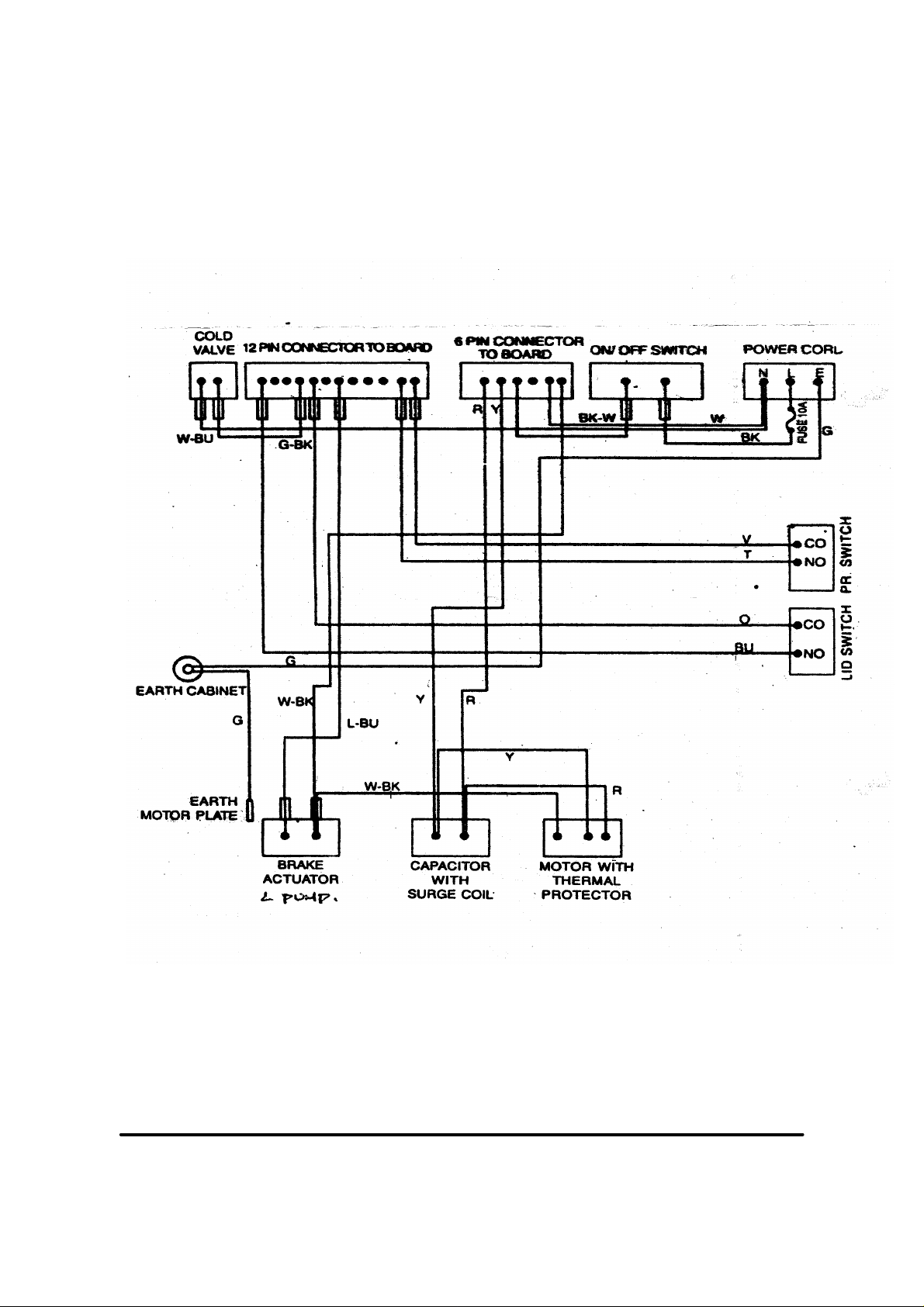
Wiring Diagram
This document is only intended for qualified technicians who are aware of the respective safety regulations.
Revised on 07/01/2003 Subject to modification
Document No. WOI/WM/2003/001
Page 11
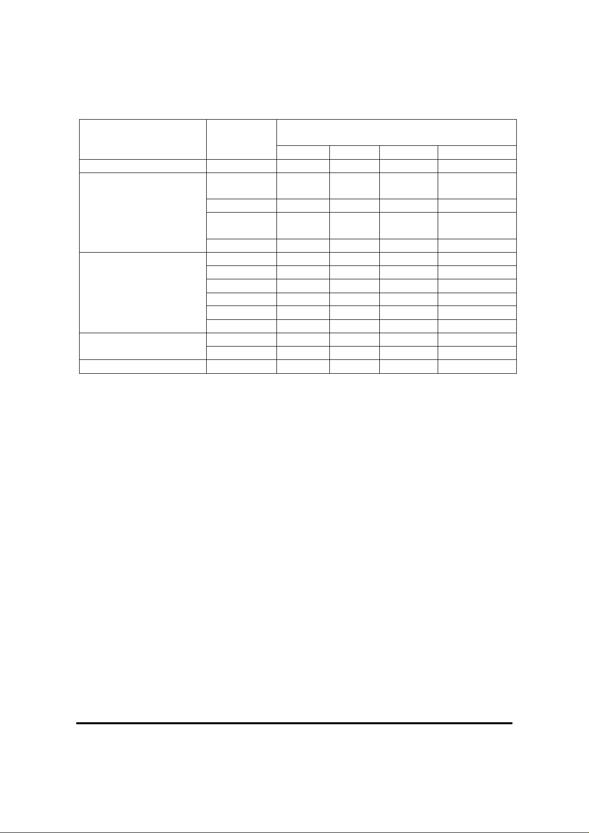
PROGRAM TIMIMG (TIME IN MINUTES)
OPERATION Sequence Wash Program
NORMAL SPEEDY DELICATE HEAVY
Fill - - - -
Agitronic Soak Soak/Agitation 32 - 32(By
selection)
Wash Agitation 14 8 4 4
Soak/Agitation - - 4 4
Agitation - - 2 14
RINSE Drain,Max 4 4 4 4
SIS 2 2 2 Spin - - - 2
Fill - - - Agitation - - - 4
Drain,Max - - - 4
SPIN SIS 2 2 4 2
Spin 8 4 - 8
TOTAL TIME(Excluding fill) 72 30 26 56
32(By selection)
Note:
1.Fill time not included in the above table.
2.Agitation rate for Normal,speedy &Heavy is 65 SPM and Delicate is 45 SPM
This document is only intended for qualified technicians who are aware of the respective safety regulations.
Revised on 07/01/2003 Subject to modification
Document No. WOI/WM/2003/001
Page 12

USER INSTRUCTIONS
? Load Laundry
? Fill required amount of Water Manually
? Add Detergent and Adjuncts as required
? Program the machine (Normal/Wash)
? Press Start
? M/C Washes as per the program and stops
? Water filling should be controlled manually. The in built pressure switch is provided to ensure minimum water level of
25 Ltrs. thus avoiding agitation without water.
? Fill fresh water for rinsing operation.
? Program the machine (Normal/Rinse and Spin)
? Press Start
? Machine Rinses as per the selected Program and stops.
? SPIN
? Spin action will take place only if water level comes below less than 12 Itrs. inside the TUB.
This document is only intended for qualified technicians who are aware of the respective safety regulations.
Revised on 07/01/2003 Subject to modification
Document No. WOI/WM/2003/001
Page 13
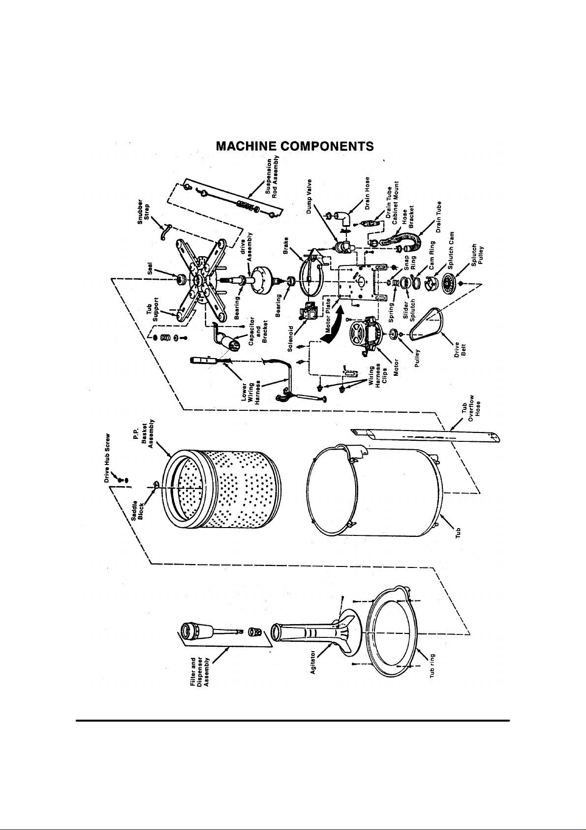
This document is only intended for qualified technicians who are aware of the respective safety regulations.
Revised on 07/01/2003 Subject to modification
Document No. WOI/WM/2003/001
Page 14
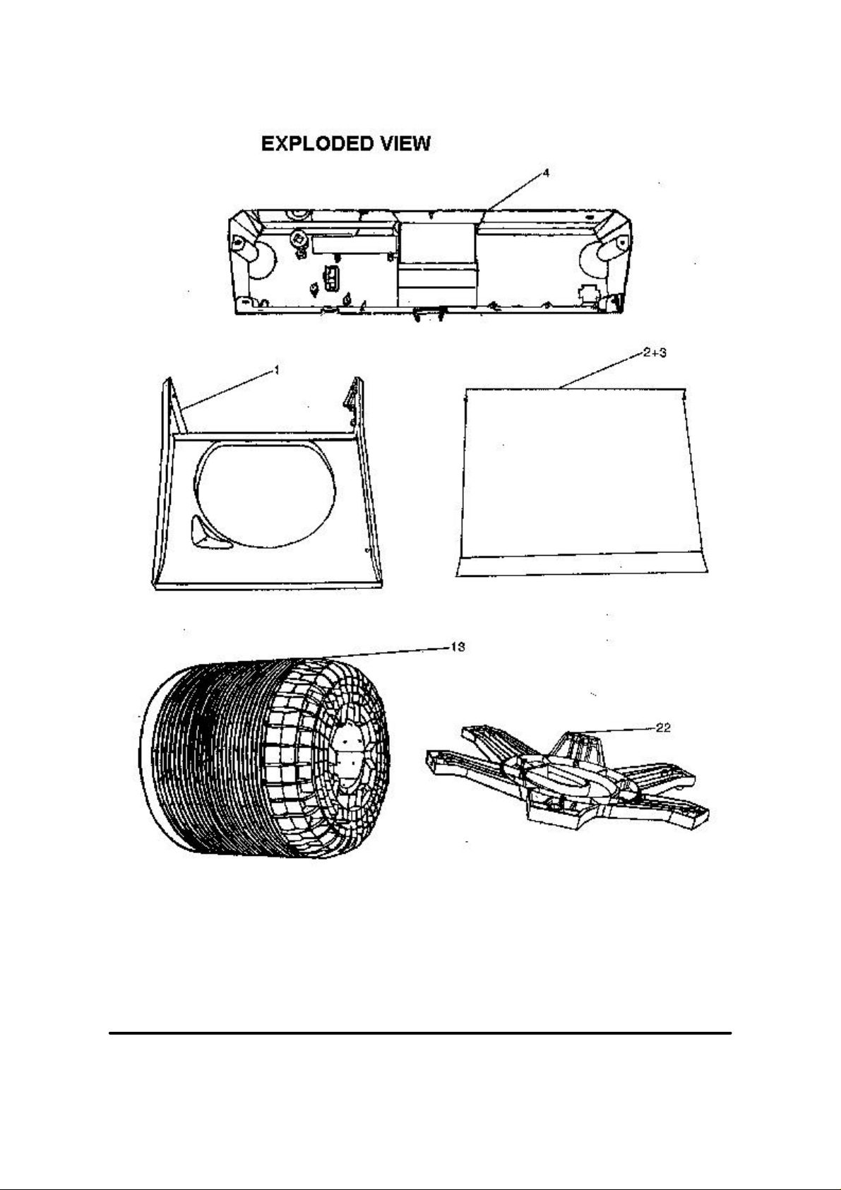
This document is only intended for qualified technicians who are aware of the respective safety regulations.
Revised on 07/01/2003 Subject to modification
Document No. WOI/WM/2003/001
Page 15
This document is only intended for qualified technicians who are aware of the respective safety regulations.
Revised on 07/01/2003 Subject to modification
Document No. WOI/WM/2003/001
Page 16
This document is only intended for qualified technicians who are aware of the respective safety regulations.
Revised on 07/01/2003 Subject to modification
Document No. WOI/WM/2003/001
Page 17
1
1
1
1
1
1
1
1
1
1
1
1
1
1
1
1
1
1
1
1
1
1
1
1
1
1
1
1
1
1
1
1
1
1
1
1
Modified parts list follows
This document is only intended for qualified technicians who are aware of the respective safety regulations.
Revised on 07/01/2003 Subject to modification
Document No. WOI/WM/2003/001
Page 18
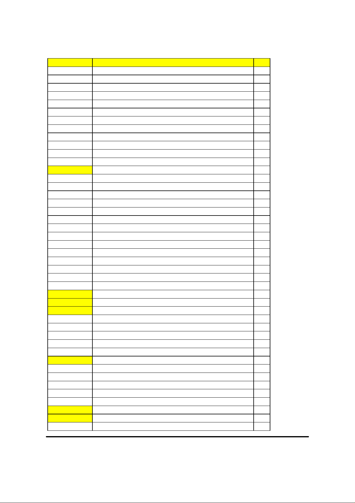
PARTS LIST
Part Code Description 3775
P0132003300 ACCEPTANCE STICKER 1
P014290020A ADHESIVE TAPE - WHIRLPOOL 1
P010110010E AGITATOR 1
P010113020A BALANCE RING ASSY (APWH) 1
P0129130100 BASKET ASSY. COMPLETE - AGI PL5 1
S012620010A BEARING-BALL SEALED 2
P012900010A BRACKET SUSPENSION 1
P010111500D BRACKET-CAPACITOR 1
P010111140B BRAKE & ARM ASSY. 1
P0125210100 BUSH - CABINET 1
P010111400A CAM RING-SPLUTCH 1
P010111520B CAM-SPLUTCH 1
P0168160200 CAPACITOR- 110V/50HZ 1
S014010100A CLAMP - ID 13.9/13.3 1
S014010010A CLAMP-33 DIA. 2
1120000003 CLING FILM (15 MICRON, 150 mm, 600 m) 1
P010142030C CLIP - CONTROL KNOB 1
S011000010C COACH BOLT - M8 X 20 1
P014311030A CONNECTOR - TORQUE MOTOR 1
P012941250G CONTROL PANEL - (A) APWH 1
P0168400600 CONTROL PANEL ASSY (APWH)AGIPL5,110V 1
P012990110C CORNER POST - WW 1
P0168200100 COVER DRAIN HOLE (WHITE) - PUMP 1
P0101111200 CUP WASHER - PULLEY SPLUTCH 1
P0129900600 CUSHION - CONTROL PANEL A/S 1
P012990120B CUSHION BALANCE RING (A/S) 1
P012990130D CUSHION BOTTOM - WW 1
P0136180100 DRAIN HOSE - EXPORT 1
P012911080A DRIVE ASSY - WW (PES) - ADC 1
P0168114600 DRIVE BELT - 60HZ 1
P012913020B DRIVE HUB - MACHINED (PL. BASKET) 1
P012931010A DUCT (A/S) 1
P010111180B DUMP VALVE ASSY. 1
P0127410300 EARTH WIRE ASSY (WW) 1
P012941150F escutcheon(a) - cogy 1
P0172710100 FILL HOSE ASSY. COMP. - Barbados 1
P010770010C FOOT 1
P0110100200 GUIDE - LEFT DRAIN 1
P012960030B HINGE (A/S) 1
P012531010B HOSE - COLD VALVE (TM) 1
P0152100100 hose - tub to dv ( heater) 1
P011011010C HOSE CONNECTOR (L BEND) APP. WHITE (S) 1
P0168200200 HOSE-L.BEND TO PUMP 1
P010110100A HOSE-TUB OVER FLOW 1
This document is only intended for qualified technicians who are aware of the respective safety regulations.
Revised on 07/01/2003 Subject to modification
Document No. WOI/WM/2003/001
Page 19
Part Code Description 3775
P014320020A HOUSING - FIXED FOOT 1
P0143200600 HOUSING ADJUSTABLE FOOT 1
P012960190E LID - BOTTOM (A/S) - APWH 1
P012960180G LID (TOP) (A/S) - APWH 1
P012960170C LID ASSEMBLY WITH GLASS(A/S)APWH 1
P012960040B LID GLASS - A/S 1
P0129901700 LID PAD - A/S 1
S0116300100 LOCK WASHER - M8 (BRAKEBAND&CLUTCH ARM) 1
P010111130C LOCK-SOLENOID BRAKE ARM 1
P012911040A MOTOR PLATE WITH BEARING 1
P0168160300 MOTOR (110V) - WW 1
P0173110500 MOTOR PLATE ASSY - 110V with Pump 1
P0168114100 MOTOR PULLEY ASSY - WW (60HZ) 1
S011590010A NUT NYLOC 2
S011590020B NUT-PUSH IN 1
P012990160A PAD - CUSHION BOTTOM (WW) 1
P0168540100 PCB ASSEMBLY (A) 110V, 1
P0106900900 PLASTIC BAG 1
P03CA10060C PLUG - INLET VALVE - COOL GREY 2C 1
P012930130A PLUG - TOP (A/S) APWH 1
P011650010C POWER "ON-OFF" SWITCH 1
P012941010H PRESSURE SWITCH (A) 1
P0168400700 PROTECTOR ASSY (APWH) A/S(W.PUMP),110V 1
P010111150E PULLEY - SPLUTCH 1
P013822040A PUMP - PLASET - 110 ~ 127V -60 HZ 1
P0173220100 PUMP ASSY.COMP - 110V 1
P011114020B RETAINER - SPRING (FRONT) 1
P010113110B SADDLE BLOCK 1
P010111510D SEAL-TUB SUPPORT 1
P010111070E SLIDER-SPLUTCH 1
S011600250A SPACER - 12 X 5 X 3 THICK. 1
P010111390A SPRING - SPLUTCH (CONICAL) 1
P0101101100 SPRING-RETAINER 1
P010100010A STRAIN RELIEF - SBR 52 1
P010110030A STRAP-SNUBBER 1
P011114010B SUSP. ASSEMBLY (FRONT) 1
P010114020G SUSP.ASSY. (REAR) 1
P010100020A SUSPENSION BALL-UPPER 1
P012930140D SWITCH KICKOUT (A/S) 1
P011210040B THROUGH CAB. CONNECTOR 1
P0168310300 TOROID COIL MODULE - (110V) 1
P0168310100 TORQUE MOTOR (110V) 1
P010112000C TUB ASSY. 1
P012910010E TUB RING (A/S) - APWH 1
P0101110100 TUB SUPP. BRG & SEAL ASSY 1
P010115010A TUBE & DISPENSER ASSY. 1
This document is only intended for qualified technicians who are aware of the respective safety regulations.
Revised on 07/01/2003 Subject to modification
Document No. WOI/WM/2003/001
Page 20

Part Code Description 3775
S0140000100 TWIST CLIP 2
P0168800100 USER MANUAL - A/S 110V, 1
S011600070A WASHER 2
S0116001900 WASHER - 4.75 X 12 X 1.2 THK. 2
S0116001600 WASHER (13 X 23 X 1) 1
S0116001800 WASHER (9 X 17 X 1.6) 1
P010171140E WASHER FAUCET M/C END 1
S0116000100 WASHER-PULLEY 1
P0168310200 WATER INLET VALVE (110V) 1
S0140000200 WH / HOSE HOLDER 2
P0168160500 WIRING HARNESS (A) 110V,(WITH PUMP) 1
This document is only intended for qualified technicians who are aware of the respective safety regulations.
Revised on 07/01/2003 Subject to modification
Document No. WOI/WM/2003/001
Page 21
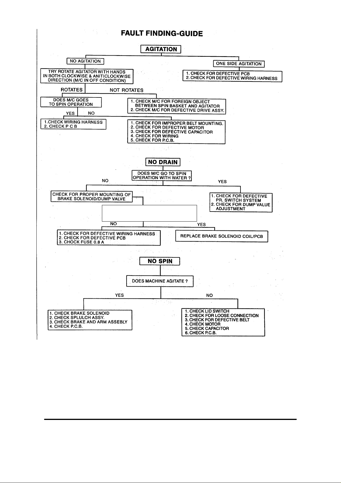
Chk the power supply at brake solinoid, is it
110 V
This document is only intended for qualified technicians who are aware of the respective safety regulations.
Revised on 07/01/2003 Subject to modification
Document No. WOI/WM/2003/001
 Loading...