

Welch Allyn SCANTEAM 3700 Wedge Technical Manual
R
SCANTEAM 3700 Wedge

This Technical Manual is used to operate and program the
SCANTEAM 3700 Wedge.
Special Pages
A Sample Bar Codes page (located on page 14-4) contains bar code
symbols you may scan to verify that your scanner has been
programmed correctly.
Charts listing the factory default selections are included on the pages
just before the Sample Bar Codes. On the programming menu pages,
default selections are indicated by a ✱" next to the bar code title.
A Bar Code Data Chart (found on the inside back cover of this manual)
contains alphanumeric bar codes for setting additional programming
options, such as the digits representing Symbology Message Length.
The information on the menu pages explains how to use this chart.
Disclaimer
Welch Allyn, Data Collection, Inc. (d/b/a Hand Held Products) reserves the right to make changes in
specifications and other information contained in this document without prior notice, and the reader should in all
cases consult Hand Held Products to determine whether any such changes have been made. The information in
this publication does not represent a commitment on the part of Hand Held Products.
Hand Held Products shall not be liable for technical or editorial errors or omissions contained herein; nor for
incidental or consequential damages resulting from the furnishing, performance, or use of this material.
This document contains proprietary information which is protected by copyright. All rights are reserved. No
part of this document may be photocopied, reproduced, or translated into another language without the prior
written consent of Hand Held Products.
E2000 Welch Allyn Data Collection, Inc. All rights reserved.
Web Address: www.handheld.com

Statement of Agency Compliance
This device complies with part 15 of the FCC Rules. Operation is subject to the
following two conditions: (1) this device may not cause harmful interference, and (2)
this device must accept any interference received, including interference that may
cause undesired operation.
FCC Class B Compliance Statement
This equipment has been tested and found to comply with the limits for a Class B
digital device pursuant to part 15 of the FCC Rules. These limits are designed to
provide reasonable protection against harmful interference in a residential
installation. This equipment generates, uses, and can radiate radio frequency
energy and, if not installed and used in accordance with the instructions, may cause
harmful interference to radio communications. However, there is no guarantee that
interference will not occur in a particular installation. If this equipment does cause
harmful interference to radio or television reception, which can be determined by
turning the equipment off and on, the user is encouraged to try to correct the
interference by one or more of the following measures:
• Reorient or relocate the receiving antenna.
• Increase the separation between the equipment and receiver.
• Connect the equipment into an outlet on a circuit different from that to
which the receiver is connected.
• Consult the dealer or an experienced radio or television technician for
help.
Caution: Any changes or modifications made to this device that are not
expressly approved by Welch Allyn, Inc. may void the user’s authority to
operate the equipment.
Note: To maintain compliance with FCC Rules and Regulations, cables connected
to this device must be shielded cables, in which the cable shield wire(s) have been
grounded (tied) to the connector shell.
Canadian Notice
This equipment does not exceed the Class B limits for radio noise emissions as
described in the Radio Interference Regulations of the Canadian Department of
Communications.
Le present appareil numerique n’emet pas de bruits radioelectriques depassant les
limites applicables aux appareils numeriques de la classe B prescrites dans le
Reglement sur le brouillage radioelectrique edicte par le ministere des
Communications du Canada.

The CE mark on the product indicates that the system has been tested to and
conforms with the provisions noted within the 89/336/EEC Electromagnetic
Compatibility Directive and the 73/23/EEC Low Voltage Directive.
For further information, please contact:
Welch Allyn Ltd.
1st Floor
Dallam Court Dallam Lane
Warrington, Cheshire WA2 7LT
England
Welch Allyn shall not be liable for use of our product with equipment
(i.e., power supplies, personal computers, etc.) that is not CE marked and
does not comply with the Low Voltage Directive.
Patents
The SCANTEAM 3700 Wedge product is covered by the following U.S. Patent: 5,932,862. Other U.S. and foreign patents pending.

TABLE OF CONTENTS
Disclaimer
Agency Compliance
SCANTEAM 3700 Wedge Description
Section Page
1.1 SCANTEAM 3700 Wedge Description 1–1. . . . . . . . . . . . . . . . . . .
1.2 Introduction 1–2. . . . . . . . . . . . . . . . . . . . . . . . . . . . . . . . . . . . . . . . . .
1.2.1 Interface Port 1–2. . . . . . . . . . . . . . . . . . . . . . . . . . . . . . . . . . . . . . . .
1.2.2 Nonvolatile Memory 1–2. . . . . . . . . . . . . . . . . . . . . . . . . . . . . . . . . .
1.3 Software Description 1–2. . . . . . . . . . . . . . . . . . . . . . . . . . . . . . . . . .
1.5 3700 Wedge Identification 1–3. . . . . . . . . . . . . . . . . . . . . . . . . . . . .
Getting Started
Section Page
2.1 Introduction 2–1. . . . . . . . . . . . . . . . . . . . . . . . . . . . . . . . . . . . . . . . . .
2.2 Connecting to a PC 2–2. . . . . . . . . . . . . . . . . . . . . . . . . . . . . . . . . . .
2.3 Terminal Selection Programming Instructions 2–3. . . . . . . . . . . . .
2.4 Quick Suffix Selections 2–4. . . . . . . . . . . . . . . . . . . . . . . . . . . . . . . .
Tailoring the Terminal and Keyboard
Section Page
3.1 Introduction 3–1. . . . . . . . . . . . . . . . . . . . . . . . . . . . . . . . . . . . . . . . . .
3.2 Country Code Selections 3–2. . . . . . . . . . . . . . . . . . . . . . . . . . . . . .
3.3 Keyboard Style Selections 3–3. . . . . . . . . . . . . . . . . . . . . . . . . . . . .
3.4 Keyboard Style Modifiers 3–4. . . . . . . . . . . . . . . . . . . . . . . . . . . . . .
Configuring the Output Parameters
Section Page
4.1 Introduction 4–1. . . . . . . . . . . . . . . . . . . . . . . . . . . . . . . . . . . . . . . . . .
4.2 Prefix/Suffix Selections 4–2. . . . . . . . . . . . . . . . . . . . . . . . . . . . . . . .
4.2.1 Prefix and Suffix Examples 4–4. . . . . . . . . . . . . . . . . . . . . . . . . . . . .
4.3 Output Selections 4–6. . . . . . . . . . . . . . . . . . . . . . . . . . . . . . . . . . . . .
Formatting the Data Message
Section Page
5.1 Introduction 5–1. . . . . . . . . . . . . . . . . . . . . . . . . . . . . . . . . . . . . . . . . .
5.1 Data Formatter Selections 5–2. . . . . . . . . . . . . . . . . . . . . . . . . . . . .
i

Symbology Menu
Section Page
6.1 Introduction 6–1. . . . . . . . . . . . . . . . . . . . . . . . . . . . . . . . . . . . . . . . . .
6.2 Industrial Symbology Selections 6–3. . . . . . . . . . . . . . . . . . . . . . . .
6.2.1 Codabar 6–3. . . . . . . . . . . . . . . . . . . . . . . . . . . . . . . . . . . . . . . . . . . . .
6.2.2 Code 39 6–6. . . . . . . . . . . . . . . . . . . . . . . . . . . . . . . . . . . . . . . . . . . . .
6.2.3 Code 93 6–10. . . . . . . . . . . . . . . . . . . . . . . . . . . . . . . . . . . . . . . . . . . . .
6.2.4 Interleaved 2 of 5 6–11. . . . . . . . . . . . . . . . . . . . . . . . . . . . . . . . . . . . .
6.2.5 Code 2 of 5 6–13. . . . . . . . . . . . . . . . . . . . . . . . . . . . . . . . . . . . . . . . . .
6.2.6 Matrix 2 of 5 6–14. . . . . . . . . . . . . . . . . . . . . . . . . . . . . . . . . . . . . . . . .
6.2.7 Code 11 and Code 128 6–15. . . . . . . . . . . . . . . . . . . . . . . . . . . . . . . .
6.3 Retail Symbology 6–17. . . . . . . . . . . . . . . . . . . . . . . . . . . . . . . . . . . . .
6.3.1 EAN (European Article Numbering) Settings 6–17. . . . . . . . . . . . . .
6.3.2 UPC (Universal Product Code) Settings 6–19. . . . . . . . . . . . . . . . .
6.3.3 EAN / UPC Addenda 6–21. . . . . . . . . . . . . . . . . . . . . . . . . . . . . . . . . .
6.3.4 MSI Settings 6–23. . . . . . . . . . . . . . . . . . . . . . . . . . . . . . . . . . . . . . . . .
6.3.5 Plessey Settings 6–24. . . . . . . . . . . . . . . . . . . . . . . . . . . . . . . . . . . . . .
Factory Settings 7–1. . . . . . . . . . . . . . . . . . . . . . . . . . . . . . . . . . . .
Firmware Utility Menu
Section Page
8.1 Introduction 8–1. . . . . . . . . . . . . . . . . . . . . . . . . . . . . . . . . . . . . . . . . .
8.1.1 Downloading Utility 8–2. . . . . . . . . . . . . . . . . . . . . . . . . . . . . . . . . . .
8.1.2 Uploading Utility 8–2. . . . . . . . . . . . . . . . . . . . . . . . . . . . . . . . . . . . . .
8.1.3 Temporary Serial Communication Configuration 8–2. . . . . . . . . .
Supported Interface Keys
Section Page
9.1 Keyboard Function Relationships 9–1. . . . . . . . . . . . . . . . . . . . . . .
System Hardware Description
Section Page
10.1 Introduction 10–1. . . . . . . . . . . . . . . . . . . . . . . . . . . . . . . . . . . . . . . . . .
10.2 General Characteristics of the 3700 Wedge 10–1. . . . . . . . . . . . . .
10.2.1 Mechanical Layout of the 3700 Wedge 10–1. . . . . . . . . . . . . . . . . .
10.2.2 Single Modular Input /Output/Power Port 10–6. . . . . . . . . . . . . . . .
10.2.3 Audible Indicator 10–7. . . . . . . . . . . . . . . . . . . . . . . . . . . . . . . . . . . . . .
10.2.4 Mounting Inserts 10–7. . . . . . . . . . . . . . . . . . . . . . . . . . . . . . . . . . . . . .
10.3 Operating Theory 10–7. . . . . . . . . . . . . . . . . . . . . . . . . . . . . . . . . . . . .
Troubleshooting And Maintenance
Section Page
11.1 Troubleshooting 11–1. . . . . . . . . . . . . . . . . . . . . . . . . . . . . . . . . . . . . .
Customer Support
Section Page
12.1 Obtaining Factory Service 12–1. . . . . . . . . . . . . . . . . . . . . . . . . . . . .
12.2 Help Desk 12–2. . . . . . . . . . . . . . . . . . . . . . . . . . . . . . . . . . . . . . . . . . .
ii

Limited Warranty 13–1. . . . . . . . . . . . . . . . . . . . . . . . . . . . . . . . . . . .
Default Charts
Section Page
14.1 Interface Menu Defaults 14–1. . . . . . . . . . . . . . . . . . . . . . . . . . . . . . .
14.2 General Operating Menu Defaults 14–1. . . . . . . . . . . . . . . . . . . . . . .
14.3 Symbology Menu Defaults - Industrial 14–2. . . . . . . . . . . . . . . . . . .
14.4 Symbology Menu Defaults - Retail 14–3. . . . . . . . . . . . . . . . . . . . . .
14.5 Sample Bar Codes 14–4. . . . . . . . . . . . . . . . . . . . . . . . . . . . . . . . . . . .
Appendix A – Technical Specifications
Section Page
A.1 Scanner Performance A–1. . . . . . . . . . . . . . . . . . . . . . . . . . . . . . . . .
A.2 Optical Specifications A–1. . . . . . . . . . . . . . . . . . . . . . . . . . . . . . . . .
A.3 Electrical Specifications A–2. . . . . . . . . . . . . . . . . . . . . . . . . . . . . . .
A.4 Environmental Specifications A–3. . . . . . . . . . . . . . . . . . . . . . . . . . .
Appendix B – ASCII Conversion Table B–1. . . . . . . . . . . . . . . .
Glossary
Figures
Number Page
Figure 1. Symbology Chart 4–5. . . . . . . . . . . . . . . . . . . . . . . . . . . . . . . . . . . .
Figure 2. Hex to ASCII Conversion Chart 4–5. . . . . . . . . . . . . . . . . . . . . . . .
Figure 3. Basic System Operation 9–1. . . . . . . . . . . . . . . . . . . . . . . . . . . . . .
Figure 4. SCANTEAM 3700 Wedge Dimensions 9–2. . . . . . . . . . . . . . . . .
Figure 5. Mounting Dimensions for the 3700 Wedge 9–3. . . . . . . . . . . . . .
Figure 6. Examples of SCANTEAM 3700 Wedge Bar Code
Orientation 9–4. . . . . . . . . . . . . . . . . . . . . . . . . . . . . . . . . . . . . . . . . .
Figure 7. SCANTEAM 3700 Wedge Pitch, Skew and Tilt Tolerance 9–5
Figure 8. Specular Reflection Interference 9–5. . . . . . . . . . . . . . . . . . . . . . .
Figure 9. Scanner Illumination Clearance 9–6. . . . . . . . . . . . . . . . . . . . . . .
Figure 10. Basic Scanner/Decoder Operation 9–7. . . . . . . . . . . . . . . . . . . .
iii

iv

SCANTEAM 3700 Wedge Description
1.1 Introduction
This chapter explains the SCANTEAM 3700 Wedge setup for use in the design lab
and a brief description of installation in a host instrument. The setup procedures are
intended for a technician or design engineer to explore the functions and features of
the 3700 Wedge in a hands–on setting, before the 3700 Wedge is embedded in host
equipment. The System Hardware Description section includes the general
mounting dimensions of the 3700 Wedge.
Setup and installation includes unpacking the unit, checking for possible damage
during shipment, and connecting the Machine Mount CCD to the host system. The
host system will typically be a PC/DOS computer with an external keyboard.
The Hand Held Products SCANTEAM 3700 Wedge is a fixed mount CCD bar code
scanner with integral decoder for easy integration into host equipment. Typical host
equipment with bar code requirements satisfied by the 3700 Wedge include
automated clinical chemistry analyzers, pharmaceutical label verification systems,
industrial automation equipment, robotic systems, materials handling equipment,
library systems, point of sale terminals and office equipment.
1
The 3700 Wedge features Hand Held Products’ time proven decoding algorithms in a
microprocessor controlled bar code scanner/decoder and offers configurable
operating parameters, providing you with the capability to tailor the 3700 Wedge to
your present requirements and the flexibility to meet your future application
requirements.
The following features are available with every SCANTEAM 3700 Wedge:
• Economical, reliable, safe CCD scanning technology
• Autodiscrimination of 12 bar code symbologies
• 100 scans per second
• Decoder configurable for high security
• Scan voting to ensure bar code data integrity
SCANTEAM 3700 Wedge Technical Manual
1–1

1.2 SCANTEAM 3700 Wedge Hardware Description
The SCANTEAM 3700 Wedge housing is molded ABS formed to enclose the optics
platform and electronics. Housing width is 3.5 inches (88.9mm). The housing length
is 2.9 inches (73.7mm) and the height is fixed at 1.05 inches (26.7mm).
The scanner uses red (660 nm wavelength) LED’s to illuminate the bar code label. A
CCD (charge coupled device) is used as an image or reading sensor. The scanned
code is converted to a digital signal in the scanner, then decoded and sent to the
host computer or system.
1.2.1 Interface Port
The SCANTEAM 3700 Wedge has one port for I/O and Power. The port is a 10 pin
RJ11 modular female connector. Cables are available from Hand Held Products for
evaluation of the 3700 Wedge. A modular connector was chosen as the standard
configuration for ease in servicing the scanner once installed.
1.2.2 Nonvolatile Memory
The 3700 Wedge contains nonvolatile FLASH memory which is used to store
operating parameters configured by means of bar code menu.
1.3 SCANTEAM 3700 Wedge Software Description
SCANTEAM 3700 Wedge software employs Hand Held Products’ time proven
decoding algorithms, controls the microprocessor functions, decodes the bar codes,
and formats the output messages.
The 3700 Wedge standard default parameters can be easily reconfigured to meet
most scanning requirements. Application specific features and options are
configurable through menus.
The 3700 Wedge can be configured to autodiscriminate among the following bar
code symbologies and their variations: Codabar, Code 39, Code 93, Code 128, Code
2 or 5, Matrix 2 of 5, Code 11, Interleaved 2 of 5, UPC, EAN, EAN/UPC Addenda,
MSI, and Plessey. Most common bar code options, such as validating symbol
length and optional check character, are supported and easily selected.
In addition to decoding selections; data output formats, such as prefix and suffix
strings, and operating parameters are also configurable.
1–2
SCANTEAM 3700 Wedge Technical Manual
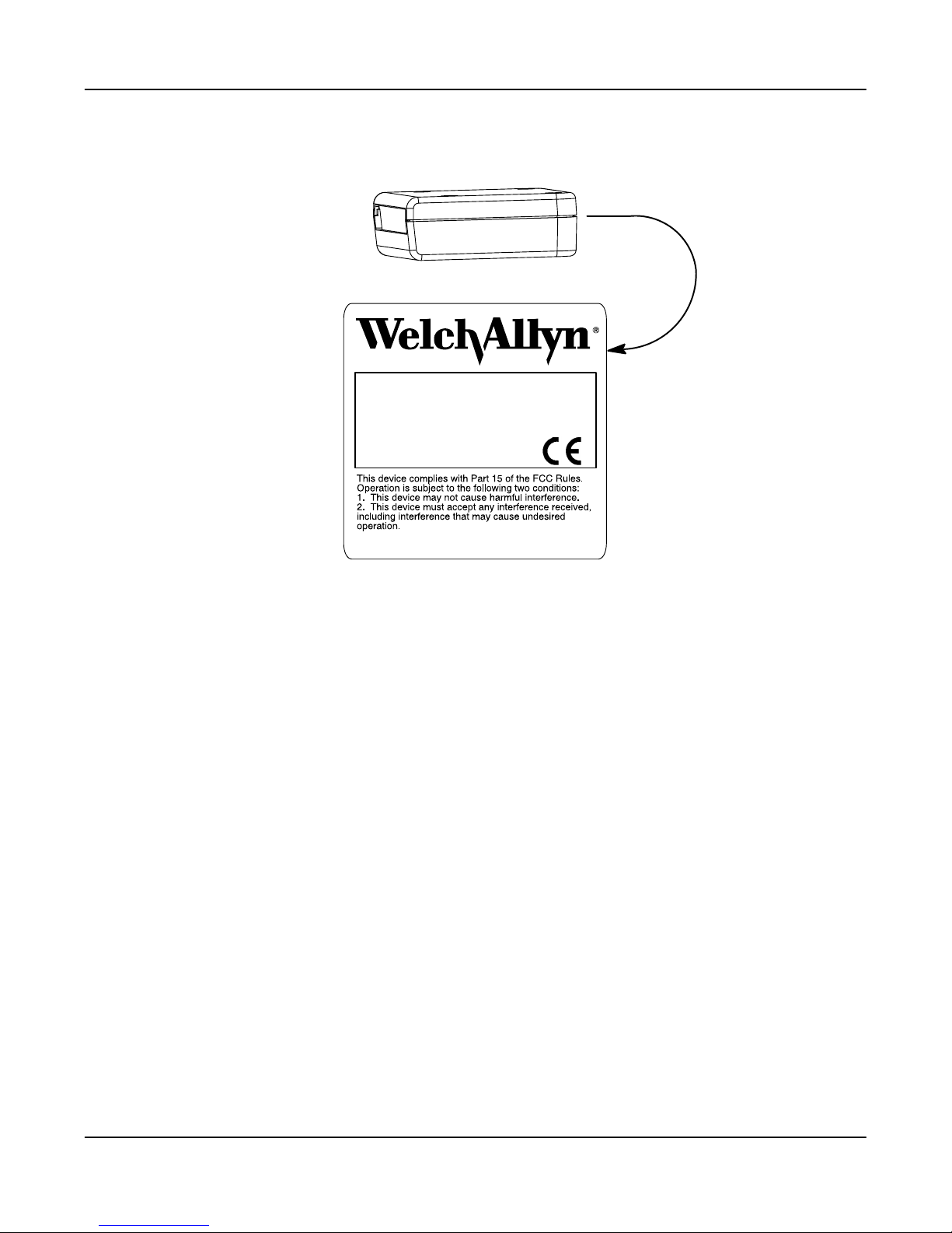
1.4 3700 Wedge Identification
ST3700
NEAR CONTACT DECODED OUTPUT
ITEM# 3700-XYZ
SOFTWARE# 31203795-XYZ
DATE - S/N H-04-1234
www.welchallyn.com
MADE IN USA PATENT 5,294,783
Enlarged View of Label
SCANTEAM 3700 Wedge Technical Manual
1–3

1–4
SCANTEAM 3700 Wedge Technical Manual

Getting Started
2.1 Introduction
Use this chapter to install and program the SCANTEAM 3700 Wedge to work with
your terminalā/ācomputer.
This section contains the following areas:
• Connecting to a PC
• Terminal Selection
• Quick Suffix Selections
About Terminal Selection Programming
With Terminal Selection programming, you program the 3700 Wedge for any
supported terminalā/ācomputer.
About Quick Suffix Programming
2
With Quick Suffix programming, you can either program the 3700 Wedge for a
carriage return suffix, or clear all suffixes.
Additional Programming Options
If you need additional programming options, refer to Section 3 (Tailoring the
Terminal and Keyboard), Section 4 (Output Parameters Menu), or Section 5
(Symbology Menu) to configure the 3700 Wedge to:
• select factory default settings
• any variation of the programmable features available.
SCANTEAM 3700 Wedge Technical Manual
2–1
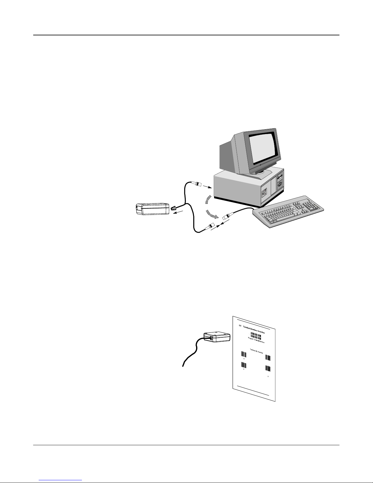
2.2 Connecting to a PC
Install the 3700 Wedge by following the steps shown below:
➊ Disconnect power to the terminal/computer by turning the host system
➋ Connect the interface cable to the 3700 Wedge and to the
OFF.
terminal/computer and to the keyboard.
Disconnect
(Cable, Keyboard, and Terminal will vary.)
➌ Once the 3700 Wedge has been fully connected, restore power to the
terminal/computer by turning the host system power ON.
➍ You must program the 3700 Wedge to work with your terminal or computer
by scanning the appropriate programming bar code(s).
Scan Terminal Interface Bar Code
For further installation and mounting information, see Chapter 10.
2–2
SCANTEAM 3700 Wedge Technical Manual
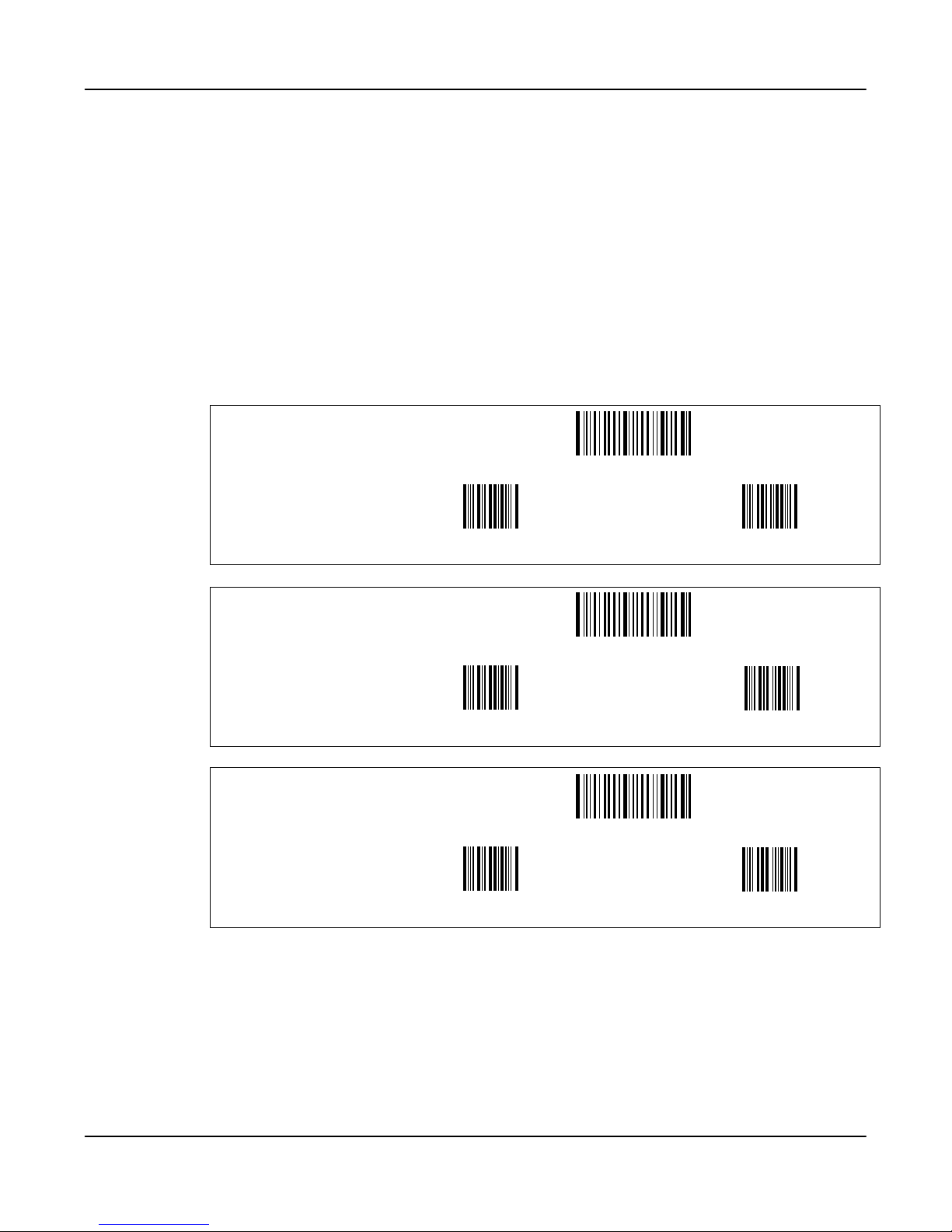
2.3 Terminal Selection Programming Instructions
Use this section to program the 3700 Wedge to work with any supported terminal or
computer.
To program the 3700 Wedge:
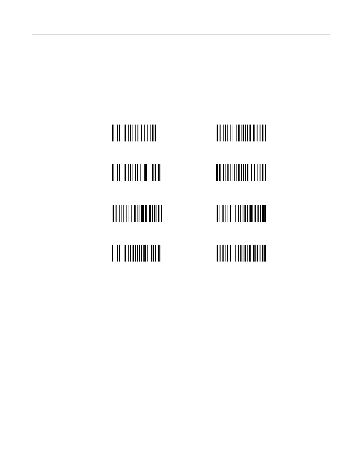
➊ Locate the twoĆdigit terminal I.D. number for your terminal or computer.
➋ Scan the Program Terminal Interface bar code.
➌ Scan the bar code representing the first digit of the terminal I.D. number.
(e.g., for an IBM AT, scan the number 0.)
➍ Scan the bar code representing the second digit of the terminal I.D.
number. (e.g., for an IBM AT, scan the number 3.)
Terminal/Model Terminal ID
IBM PC/XT 01
Program Terminal Interface
0 1
Terminal/Model Terminal ID
IBM PS/2 25, 30 02
Program Terminal Interface
0 2
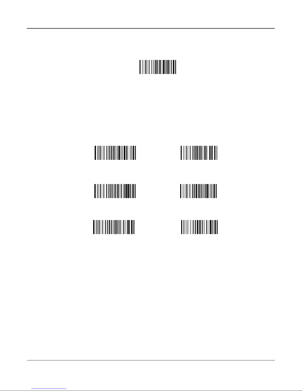
Terminal/Models Terminal ID
IBM AT, PS/2
30-286, 50,
03
Program Terminal Interface
55SX, 60, 70,
70-061,
70-121, 80
0 3
Your terminal interface is set up.
If you wish to program a carriage return (CR) suffix or turn off the carriage return (or any other
suffix), see the Quick Suffix Selections" on the next page.
SCANTEAM 3700 Wedge Technical Manual
2–3

2.4 Quick Suffix Selections
If you want a carriage return suffix, scan the Carriage Return Suffix - Yes
bar code. This will program a carriage return (CR) suffix for all enabled bar
code symbologies. Scanning this bar code clears all previously
programmed prefixes and suffixes.
Scan the Carriage Return Suffix - No bar code to disable (or clear) all
previously programmed prefixes and suffixes (such as the carriage return
prefix).
Carriage Return Suffix - Yes
Carriage Return Suffix - No
2–4
SCANTEAM 3700 Wedge Technical Manual

Tailoring the Terminal And Keyboard
3.1 Introduction
Use this chapter to program the SCANTEAM 3700 Wedge for General Operating
features.
This programming section contains the following menu selections:
• Country Code Selections
• Keyboard Selections
About Country Code Programming
Country Code programming allows you to:
• Select a Foreign Keyboard
About Keyboard Programming
Keyboard programming allows you to:
3
• Select the Keyboard Style for your terminal
• Select the Keyboard Style Modifiers for your terminal
SCANTEAM 3700 Wedge Technical Manual
3–1
3.2 Country Code Selections
Foreign Keyboards
This programming selection allows you to reĆmap the keyboard layout for the
selected country. Default = United States.
As a generalrule, the followingcharacters arenot supported bythe 3700 Wedge
for countries other than the United States:
@|$#{}[]=/`\<>~
✱ United States
Denmark, Finland, Norway, Sweden
Germany, Austria
Switzerland
Belgium
France
Italy
United Kingdom
3–2
SCANTEAM 3700 Wedge Technical Manual

3.3 Keyboard Style Selections
This programming selection allows you to programthe 3700 Wedge to support
special keyboard features, such as Caps Lock and SHIFT LOCK.
Regular is used when you normally have the Caps Lock key off.
Caps Lock is used when you normally have the Caps Lock key on.
Shift Lock is usedwhen you normally have theShift Lock key on. (Not common
to U.S. keyboards.)
Automatic Caps Lock is used if you change Caps Lock key On and Off. The
software tracks and reflectsif you have CapsLock on or off. (AT and PS/2 Only.)
Requires systems with keyboard Caps Lock status LED.
Emulate External Keyboard is scanned if you do not have an external
keyboard. (IBM AT or equivalent).
✱ Regular
Shift Lock Automatic Caps Lock
Emulate External Keyboard
Caps Lock
SCANTEAM 3700 Wedge Technical Manual
3–3
3.4 Keyboard Style Modifiers
Default All Keyboard Style Modifiers
This programming selection allows you to programthe 3700 Wedge to support
special keyboard features, such as CTRL+ codes and Turbo Mode.
Control + ASCII Mode On - If you scan this selection,the 3700 Wedge sends
key combinations for ASCII control characters for values 00-1F. Refer to page
9-1 for CTRL+ Values. Default = Off
Turbo Mode On - Ifyou scanthis selection,the 3700Wedge sendscharacters
faster. (IBM AT only) Default = Off
Numeric Output from Keypad - If you scan this selection, the 3700 Wedge
sends numeric characters as if entered from a numeric keypad. Default =
Numeric Output from Main Keyboard
Control + ASCII Mode On
Turbo Mode On
Numeric Output from Keypad
✱ Control + ASCII Mode Off
✱ Turbo Mode Off
✱ Numeric Output from Main Keyboard
3–4
SCANTEAM 3700 Wedge Technical Manual

Configuring Output Parameters
4.1 Introduction
Use this chapter to program the SCANTEAM 3700 Wedge for Interface operation.
This programming section contains the following menuing selections:
• Prefix and Suffix Selections
• Output Selections
• Data Formatter Selections
About Prefix and Suffix Programming
Prefix and Suffix programming allows you to:
• Set Interface Prefixes and Suffixes
• Clear One or All Prefixes
• Clear One or All Suffixes
4
You may save your current PrefixĂ/ĂSuffix changes or discard them, as you wish.
About Output Programming
Output programming allows you to:
• Set the Beeper Volume
• Set Output Delays (Intercharacter, Interfunction, or Intermessage)
• Program Reread or Good Read Delays
• Enable or disable Voting
• Enable or disable Code I.D. or AIM I.D. transmission
• Enable or disable Function Code transmission
4–1SCANTEAM 3700 Wedge Technical Manual

4.2 Prefix/Suffix Selections
The 3700 Wedge will transmit a decoded message after every successful bar
code read. Prefix and Suffix characters are data characters you may assign
to be sent before and after the transmitted bar code data.
Transmitted data frame –>
Characters for the Prefix and Suffix are selected by their hexadecimal ASCII
value, up to 12 characters each. Prefix and Suffix characters may be sent for
a specific symbology, or may be sent with all bar code scans. Default Prefix =
none. Default Suffix = none.
Programming Steps to Add an Interface Prefix / Suffix:
➊ To add a Prefix, scan the Add Prefix programming bar code.
To add a Suffix, scan the Add Suffix programming bar code.
➋ Refer to the Symbology Chart (page 4-5) to find the Hex value that
represents the symbology(s) you want transmitted with one or more
Prefixes orSuffixes. Scan the two digits on the Programming Chart (on
the inside of the back cover of this menu).
➌ Refer to the Hex ASCII Chart (page 4-5) to find the Hex value that
represents the ASCII characters you wish to transmit with the bar code
data. Use the Programming Chart (inside back cover) to scan the
alphanumeric combination that represents the ASCII characters.
➍ To complete PrefixĂ/ĂSuffix programming, scan either:
H Save Current Prefix or Suffix Changes[ programming bar code.
This exits, saving the PrefixĂ/ĂSuffix selections you just assigned.
H Discard Current Prefix or Suffix Changes programming bar
code. This exits without changing the PrefixĂ/ĂSuffix.
[ You may also start scanning bar codes; your PrefixĂ/ĂSuffix selections will be saved.
Programming Steps to Clear (or Delete) One Prefix / Suffix Entry:
➊ To clear the Prefix entry for a specific symbology, scan the Clear One
Prefix programming bar code.
To clear the Suffix entry for a specific symbology, scan the Clear One
Suffix programming bar code.
➋ Refer to the Symbology Chart to find the Hex value representing the
symbology's entry you want cleared. Scan the two digits on the
Programming Chart (on the inside of the back cover of this menu).
➌ You don't need to scan Save Current ... Changes or Discard Current
... Changes programming bar codes to complete programming.
Prefix SuffixBar Code Message
Other Programming Selections: Scanning the Clear All Prefixes or Clear All
Suffixes bar code deletes all
the Save Current ... Changes or Discard Current ... Changes programming
bar code to complete programming.
Note: PrefixĂ/ĂSuffix programming examples may be found on page 4-4.
4–2
Prefix or Suffix selections. You don't need to scan
SCANTEAM 3700 Wedge Technical Manual

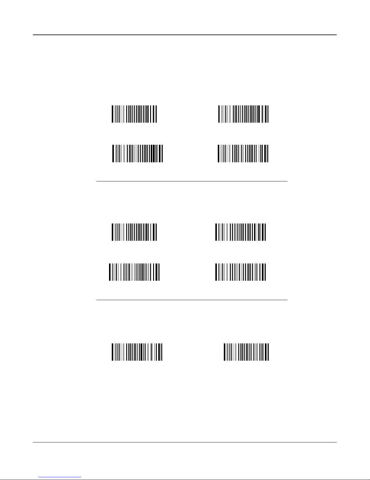
Interface Prefix Selection
Add Prefix ] Clear All Prefixes
Clear One Prefix ]
Interface Suffix Selection
Add Suffix ]
Clear One Suffix ]
Clear All Suffixes
Exit Selection for Prefix / Suffix
Save Current Prefix or Suffix Changes
Discard Current Prefix or Suffix Changes
] One or more twoĆdigit numbers are required after scanning this programming bar
code. Please scan your selection on the Programming Chart (inside back cover).
4–3SCANTEAM 3700 Wedge Technical Manual

4.2.1 Prefix and Suffix Examples
Example 1: Add Suffix for Specific Symbology
You want to send a CR (carriage return)ĂSuffix for UPC only.
H Scan the Add Suffix Suffix Selection bar code.
H The SymbologyChart indicates that the Hex value of UPCis 63". Scan
6 and 3 on the Programming Chart (inside back cover).
H A CR" is equivalent to 0D" (see the Hex ASCII Chart). Scan 0 and D
on the Programming Chart.
H Scan the Save Current Suffix Changes Exit Selection bar code.
Example 2: Add Suffix for ALL Symbologies
You want to send a CR (carriage return)ĂSuffix for all symbologies.
H Scan the Add Suffix Suffix Selection bar code.
H The Symbology Chart indicates that the Hex value for All Symbologies
is 99". Scan 9 and 9 on the Programming Chart.
H A CR" is equivalent to 0D". Scan 0 and D on the Programming Chart.
H Scan the Save Current Suffix Changes Exit Selection bar code.
Example 3: Add Prefix for Specific SymbologyĂ/ĂSuffixfor ALL Symbologies
You want to send a HT (tab)ĂPrefix for UPC only and a CRĂ/ĂLF (carriage
returnĂ/Ăline feed) Suffix for all symbologies.
H Scan the Add Prefix Prefix Selection bar code.
H The SymbologyChart indicates that the Hex value of UPCis 63". Scan
6 and 3 on the Programming Chart.
H An HT" is equivalent to 09". Scan 0 and 9 on the Programming Chart.
H Scan the Add Suffix Suffix Selection bar code.
H The Symbology Chart indicates that the Hex value for All Symbologies
is 99". Scan 9 and 9 on the Programming Chart.
H A CR" is equivalent to 0D" and an LF" is 0A". Scan 0, D, 0, and A
on the Programming Chart.
H Scan the Save Current PrefixĂ/ĂSuffix Changes Exit Selection barcode.
Example 4: To Clear a Specific Prefix Entry
You've programmed the 3700 Wedge to send a CRĂ/ĂLF (carriage returnĂ/Ăline
feed) Prefix for all symbologies (Hex value, 99). This is one Prefix entry. You've
also programmed a #" Prefix for UPC (Hex, 63). You decide that you want to
clear the UPC entry, but not the Prefix entry for all symbologies.
H Scan the Clear Specific Prefix Prefix Selection bar code.
H The Symbology Chart indicates thatthe Hex value forUPC is 63". Scan
6 and 3 on the Programming Chart.
4–4
SCANTEAM 3700 Wedge Technical Manual
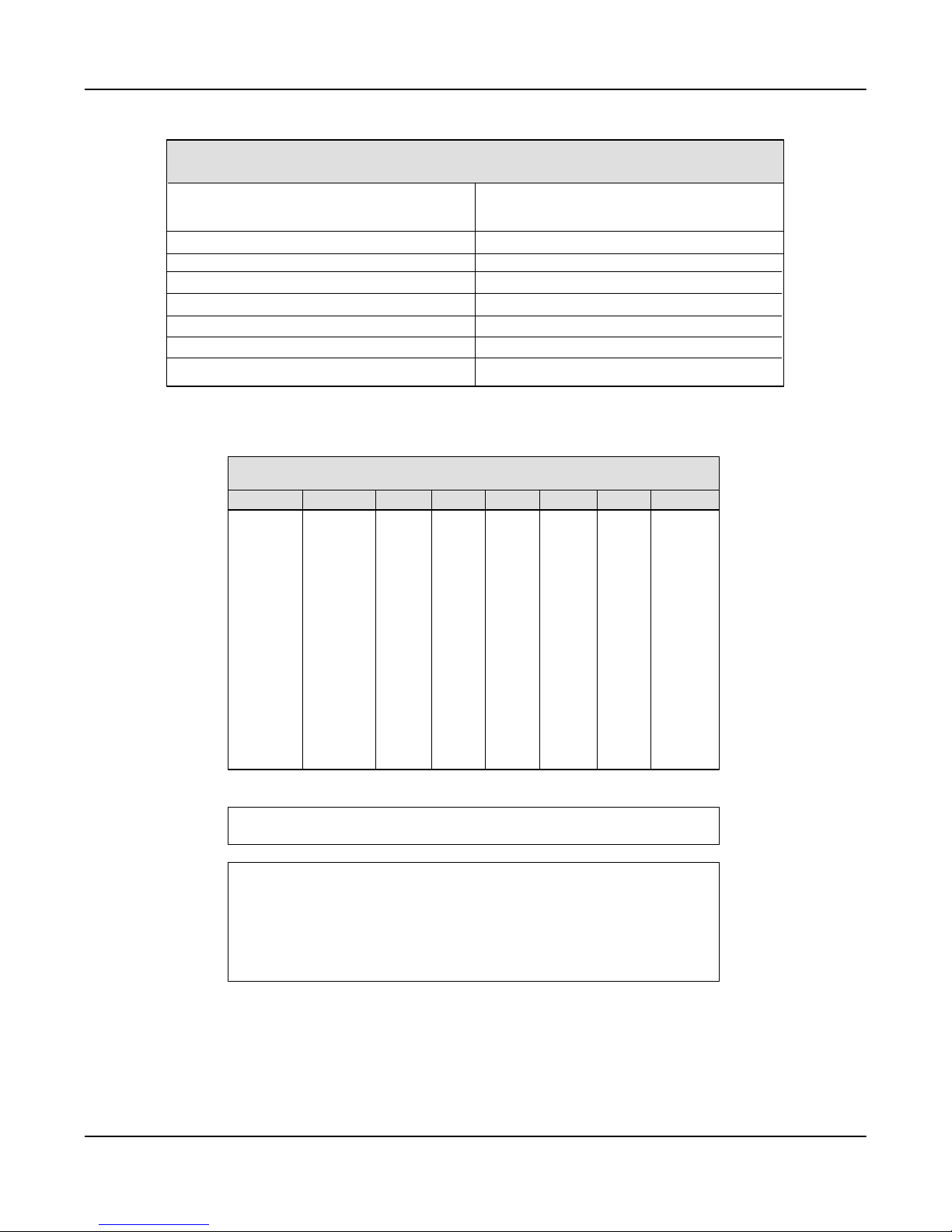
Symbology Chart
Symbology
Codabar
Code 39
UPC
EAN
Interleaved 2 of 5
Code2of5
MSI
ASCII Hex ASCII Hex ASCII HexASCII Hex ASCII Hex ASCII Hex ASCII Hex ASCII Hex
NUL
SOH
STX
ETX
EOT
ENQ
ACK
BEL
BS
HT
LF
VT
FF
CR
SO
SI
00
01
02
03
04
05
06
07
08
09
0A
0B
0C
0D
0E
0F
Code
ID
a
b
c
d
e
f
g
[
Hex
Value
61
62
63
64
65
66
67
Symbology
Code 11
Code 93
Code 128
Matrix 2 of 5
Plessey
All Symbologies
Figure 1. Symbology Chart
Hex to ASCII Conversion Chart
DLE
10
SP
20
0
30
@
DC1
DC2
DC3
DC4
NAK
SYN
ETB
CAN
EM
SUB
ESC
FS
GS
RS
US
11
12
13
14
15
16
17
18
19
1A
1B
1C
1D
1E
1F
!
21
1
"
22
#
23
$
24
%
25
&
26
'
27
(
28
)
29
*
2A
+
2B
,
2C
-
2D
.
2E
/
2F
31
2
32
3
33
4
34
5
35
6
36
7
37
8
38
9
39
:
3A
;
3B
<
3C
=
3D
>
3E
?
3F
40
A
41
B
42
C
43
D
44
E
45
F
46
G
47
H
48
I
49
J
4A
K
4B
L
4C
M
4D
N
4E
O
4F
P
Q
R
S
T
U
V
W
X
Y
Z
[
\
]
^
_
50
51
52
53
54
55
56
57
58
59
5A
5B
5C
5D
5E
5F
Code
[
ID
h
i
j
m
n
`
60
61
62
63
64
65
66
67
68
69
6A
6B
6C
6D
6E
6F
p
q
r
s
t
u
v
w
x
y
z
{
|
}
~
DEL
a
b
c
d
e
f
g
h
i
j
k
l
m
n
o
Hex
Value
68
69
6A
6D
6E
99
70
71
72
73
74
75
76
77
78
79
7A
7B
7C
7D
7E
7F
Note: PrefixĂ/ĂSuffix entries for specific symbologies override the universal (All
Symbologies, 99) entry.
Note: Adding a Prefix or a Suffix appends that PrefixĂ/ĂSuffix to any existing entries
for the symbology(s) you've chosen. For example, if you've already programmed
and saved a CRĂ/ĂLF (carriage returnĂ/Ăline feed) and add a #" Prefix, the "#"
will be sent after the CRĂ/ĂLF.
If you add a Prefixă/ăSuffix but want existing entries cleared, you'll need to use
the Clear Specific PrefixĂ/ĂSuffix programming selection first. Then use the
Add PrefixĂ/ĂSuffix programming selection to program your new PrefixĂ/ĂSuffix.
Figure 2. Hex to ASCII Conversion Chart
4–5SCANTEAM 3700 Wedge Technical Manual

4.3 Output Selections
Default All Output Selections
Scanning the Default bar code will program the 3700 Wedge to the output
options indicated by a ✱" in the menu selections on this and the following two
programming pages.
✱ Default All Output Settings ✱
Beeper Volume
This programming selection provides control of the 3700 Wedge's beeper
volume. The beeper volume may be turned off, or it may be set from low to high
in three increments. Default = High.
Off
Medium
Low
✱ High
4–6
SCANTEAM 3700 Wedge Technical Manual

Output Delays
This programming selection provides control of the Output Delays, which are
time delays between data output by the 3700 Wedge to the host terminal.
(Specific output delaysare described below.) The actualdelay is 5milliseconds
multiplied by the programmed value (00 - 99). Default = 00.
Note: To select digits 0 through 9, use the Programming Chart found on the
inside of the back cover of this menu. Scan the programming selection bar code
first, and then scan the bar code(s) representing the digits you wish to set.
Intercharacter Delay is the time delay between data characters output by the
3700 Wedge to the host terminal.
Interfunction Delay is the time delay between function (key) codes output by
the 3700 Wedge to the host terminal.
Intermessage Delay is the time delay between data messages or records
output by the 3700 Wedge to the host terminal.
Example:
H You need a 45 millisecond delay. Scan the Intercharacter Delay bar
code. Then scan 0" and 9" on the Programming Chart (09 x 5ms =
45 ms). Two digits are always required for a delay setting.
Intercharacter Delay (x5mS) ]
Interfunction Delay (x5mS) ]
] A twoĆdigit number is required after scanning this programming bar code.
Please scan your selection on the Programming Chart (inside back cover).
Intermessage Delay (x5mS) ]
4–7SCANTEAM 3700 Wedge Technical Manual
Reread Delay
This programming selection allows you to set a time period that must pass
before the 3700 Wedge can read the same bar code again. Setting a reread
delay protectsagainst accidental rereads of the same bar code. Longer delays
are effective in minimizing accidental rereads at POS (point of sale) terminals.
Use shorter delays in applications where repetitive bar code scanning is
required.
Default = Low (175 milliseconds).
✱ Low (175 milliseconds)
High (1.0 second)
Medium (450 milliseconds)
Extra High (2.0 seconds)
Good Read Delay
This programming selection allows you to set a time period that must pass
before the 3700 Wedge can read another bar code. Some terminals require a
slower read rate. By setting a good read delay, you can ensure a good read.
Default = None.
✱ None
Medium (1.0 second)
Low (500 milliseconds)
High (1.5 second)
Voting
When this selection is enabled, the 3700 Wedge requires multiple identical,
consecutive decodes beforethe bar code datawill be acceptedand transmitted
to the terminal. Default = Disable.
4–8
Enable
✱ Disable
SCANTEAM 3700 Wedge Technical Manual
Code I.D. Transmit
This programming selection allows you to enable or disable transmission of a
Code I.D. before the decoded bar code symbology. (See the Symbology Chart
on page 4-5 for the single character code that identifies each symbology.)
Default = Disable.
Enable
✱ Disable
AIM I.D. Transmit
This programming selection allows you to enable or disable transmission of an
AIM I.D. before the decoded bar code symbology. (See AIM Guidelines on
Symbology Identifiers for more information on the AIM symbology ID
characters.) Default = Disable.
Enable
✱ Disable
Function Code Transmit
When this programmingselection is enabled, andfunction codes arecontained
within the scanned data, the 3700 Wedge transmits the key code (which
corresponds to the decoded ASCII function code) to the terminal. ASCII
function codes are represented by the HEX values 00-1F. (Charts of these
function codes are shown in Section 7, Supported Interface Keys.)
Default = Enable.
✱ Enable
Disable
4–9SCANTEAM 3700 Wedge Technical Manual

4–10
SCANTEAM 3700 Wedge Technical Manual
 Loading...