

Page 1
Commercial/Retail Wedge Decoder
Page 2

Disclaimer
Welch Allyn reserves the right to make changes in specifications and
other information contained in this document without prior notice, and the
reader should in all cases consult Welch Allyn to determine whether any
such changes have been made. The information in this publication does
not represent a commitment on the part of Welch Allyn.
Welch Allyn shall not be liable for technical or editorial errors or
omissions contained herein; nor for incidental or consequential
damages resulting from the furnishing, performance, or use of this
material.
This document contains proprietary information which is protected by
copyright. All rights are reserved. No part of this document may be
photocopied, reproduced, or translated into another language without the
prior written consent of Welch Allyn, Incorporated.
Page 3

1998 Welch Allyn, Inc. All rights reserved.
Page 4

STATEMENTS OF AGENCY COMPLIANCE
This device complies with part 15 of the FCC Rules. Operation is subject to the
following two conditions: (1) this device may not cause harmful interference,
and (2) this device must accept any interference received, including
interference that may cause undesired operation.
FCC Class A Compliance Statement
This equipment has been tested and found to comply with the limits for a Class A
digital device, pursuant to part 15 of the FCC Rules. These limits are designed
to provide reasonable protection against harmful interference when the
equipment is operated in a commercial environment. This equipment
generates, uses, and can radiate radio frequency energy and, if not installed
and used in accordance with the instruction manual, may cause harmful
interference to radio communications. Operation of this equipment in a
residential area is likely to cause harmful interference, in which case the user
will be required to correct the interference at his own expense.
Caution: Any changes or modifications made to this device that are not
expressly approved by Welch Allyn, Inc. may void the user’s authority to
operate the equipment.
Note: To maintain compliance with FCC Rules and Regulations, cables
connected to this device must be
wire(s) have been grounded (tied) to the connector shell.
Canadian Notice
This equipment does not exceed the Class A limits for radio noise emissions as
described in the Radio Interference Regulations of the Canadian Department of
Communications.
Le present appareil numerique n’emet pas de bruits radioelectriques depassant
les limites applicables aux appareils numeriques de la classe A prescrites dans
le Reglement sur le brouillage radioelectrique edicte par le ministere des
Communications du Canada.
shielded
cables, in which the cable shield
Page 5

The CE mark on the product indicates that the system has been tested to and
conforms with the provisions noted within the 89/336/EEC Electromagnetic
Compatibility Directive and the 73/23/EEC Low Voltage Directive.
European Contact: European Regulatory Manager
Welch Allyn Ltd.
28 Sandyford Office Park
Foxrock, Dublin 18
Ireland
or
Welch Allyn Ltd.
1st Floor
Dallam Court Dallam Lane
Warrington, Cheshire W A2 7LT
England
Welch Allyn shall not be liable for use of our product with equipment
(i.e., power supplies, personal computers, etc.) that is not CE marked and
does not comply with the Low Voltage Directive.
Page 6

LIMITED WARRANTY
Welch Allyn, Inc., hereby warrants its products to be functional and free
from manufacturing defects at the time of delivery. Welch Allyn, Inc.
further warrants that it will replace or repair, at its option, any unit that fails
to perform according to Welch Allyn’s published specifications during a
period of two (2) years from the time of shipment by Welch Allyn, Inc. to
the user or the time it is purchased from any of Welch Allyn, Inc.’s
Authorized Distributors. Any attempt on the part of the user to
disassemble or service the equipment shall void the warranty.
The warranty does not apply to products which have been damaged by
improper handling, shipping, or misuse. The warranty does not apply, if, in
the sole opinion of Welch Allyn, Inc., the unit has been damaged by
accident, misuse, neglect, improper shipping, or handling. Since the unit is
sensitive to static, the responsibility to protect it from static damage is
solely that of the user. The warranty is valid only if the device has not been
tampered with or serviced by any party unauthorized by Welch Allyn, Inc.
as a repair facility.
THE WARRANTIES SET FORTH HEREIN ARE IN LIEU OF ANY
AND ALL OTHER WARRANTIES EXPRESSED OR IMPLIED
INCLUDING THE WARRANTIES OF MERCHANTABILITY AND
FITNESS FOR A PARTICULAR PURPOSE. THE BUYER
ACKNOWLEDGES THAT NO OTHER REPRESENTATIONS WERE
MADE OR RELIED UPON WITH RESPECT TO THE QUALITY AND
FUNCTION OF THE DEVICE HEREIN SOLD.
In no event shall Welch Allyn, Inc. or its resellers be liable for any loss,
inconvenience or damage whether direct, incidental, consequential, or
otherwise, and whether caused by negligence or other fault resulting from
the breach of any express warranty except as set forth herein. Some states
do not allow the exclusion or limitation of incidental or consequential
damages, so the above limitations or exclusions may not apply to you.
This warranty gives you specific legal rights, and you may also have other
rights which vary from state to state or country to country.
Limited Warranty iii
Page 7

iv
Limited Warranty
Page 8

TABLE OF CONTENTS
Chapter Page
ST ATEMENT OF AGENCY COMPLIANCE i
LIMITED WARRANTY iii
INTRODUCTION xiii
CHAPTER 1 – SCANTEAM 2000 DECODER
DESCRIPTION 1–1
1.1 Introduction 1–1
1.2 System Hardware Overview 1–2
1.2.1 Connection Options 1–2
1.2.2 Serial Wedge Capability 1–4
1.2.3 Cloning 1–4
1.2.4 Interface Cables/Connectors 1–7
1.3 System Software Overview 1–7
1.3.1 Programmable Selections 1–7
1.3.2 Non–Volatile Memory 1–7
1.3.3 Memory T ests 1–8
1.4 Scanning Devices 1–8
CHAPTER 2 – SYSTEM HARDWARE DESCRIPTION 2–1
2.1 Decoder Unit 2–1
2.2 Terminal Interface Cable 2–2
2.3 Interface Port 2–2
2.4 Auxiliary Port 2–3
2.4.1 Description 2–3
2.4.2 Receive Operation 2–3
2.4.3 Transmit Operation 2–4
2.5 Scanner Ports 2–4
2.6 Magnetic Stripe Triple T rackReader (MSR) Port 2–4
2.7 Power Requirements 2–6
2.7.1 Keyboard Wedge Applications 2–6
2.7.2 RS–232D Auxiliary Port 2–7
Table of Contents
v
Page 9

Chapter Page
CHAPTER 3 – SET–UP and INSTALLATION 3–1
3.1 Preparation 3–1
3.2 Set–Up Procedure 3–1
3.2.1 2000/C Set–up 3–1
3.2.2 2000/R Set–up 3–4
CHAPTER 4 – PROGRAMMING THE DECODER 4–1
4.1 Beeper Sequence and Meaning 4–1
4.2 The Programming Menu 4–2
4.2.1 Programming Menu Page 4–3
4.2.2 The Bar Code Chart 4–5
4.3 Recommended Programming Sequence 4–6
4.4 T erminal Selection Menu Page 4–7
4.5 Output Parameters Menu Page 4–8
4.5.1 Output Parameters Menu Page Continued 4–10
4.6 Code Selection I (Industrial) Programming Menu Page 4–18
4.7 Code Selection II (Retail) Menu Page 4–21
4.8 Auxiliary Port 4–24
4.9 Data Formatting 4–32
4.9.1 Data Formatter 4–32
4.10 Data Formatter Editor Selections 4–33
4.10.1 Programming Example 4–34
4.10.2 Data Formatter Priority/Hierarchy 4–36
4.11 Editor Command Sequences 4–36
4.11.1 Editing Command Examples 4–38
4.12 Welch Allyn – DCA Coded ASCII Protocol 4–42
4.12.1 DCA Character Representation 4–42
4.12.2 Programming Example – Retail 4–43
4.13 MSR Data 4–44
4.14 Keyboard Layouts and Delimiters 4–46
CHAPTER 5 – SERVICE/TECHNICAL ASSISTANCE 5–1
vi
Table of Contents
Page 10

Chapter Page
APPENDIX A – BAR CODE BASICS AND SCANNING
TECHNIQUES A–1
A.1 A Closer Look at Bar Code Symbols A–1
A.2 Bar Code Scanning A–1
A.3 Learning How to Use a Bar Code Scanner A–3
A.3.1 Wand Type Scanner A–4
A.3.2 Laser T ype Scanner A–5
A.3.3. CCD T ype Scanner A–6
A.3.4 Magnetic Stripe Reader A–7
A.3.5 Bar Code Badge Reader A–8
A.4 Caring for Your Scanner A–9
A.5 Inspection A–9
APPENDIX B – TECHNICAL SPECIFICATIONS B–1
B.1 General Operation Specifications B–1
B.2 Electrical Specifications B–2
B.3 Connector Specifications B–2
B.4 Bar Code Label Specifications B–4
APPENDIX C – CONNECTING THE 2000/R TO POS AND
PC TERMINALS C–1
C.1 NCR 2151 Interface Cable Installation C–1
C.2 NCR 2152 Interface Cable Installation C–7
C.3 NCR 2950 Interface Cable Installation C–10
C.4 IBM 3653 Interface Cable Installation C–13
C.5 IBM 3683 Interface Cable Installation C–18
C.6 IBM 4683 Interface Cable Installation C–23
C.7 NCR 7052 OCIA Port Interface Cable Installation C–24
C.8 NCR 7052 Keyboard Wedge Interface Cable Installation C–25
C.9 FUJITSU 7990 OCR Interface Cable Installation C–26
C.10 PC/XT, PC/AT, PS/2 And Data Terminal
Keyboard Wedge Interface Cable Installation C–27
APPENDIX D – KEYBOARD FUNCTION
RELATIONSHIPS D–1
D.1 Keyboard Function Relationships D–1
D.2 Index for Terminal Types D–2
D.2.1–D.2.30 Keyboard Function Codes D–33–
Table of Contents
D–36
vii
Page 11

viii
Table of Contents
Page 12

LIST OF FIGURES AND TABLES
Figures Page
1 SCANTEAM 2000 DECODER DESCRIPTION
Figure 1.1 Keyboard Wedge Connection 1–2
Figure 1.2 Direct Connection 1–3
Figure 1.3 Cloning Example 1–5
Figure 1.4 Clone Cable Pin Layout 1–6
2 HARDWARE DESCRIPTION
Figure 2.1 Front/Rear Panel Layout 2–1
Figure 2.2 Power Configuration 2–6
3 SET–UP and INST ALLATION
Figure 3.1 “Y” Interface Cable 3–2
Figure 3.2 SCANTEAM 2000 Connections 3–5
4 PROGRAMMING THE DECODER
Figure 4.1 Programming Menu Page 4–3
Figure 4.2 Bar Code Chart 4–5
Figure 4.3 One–For–One Flow 4–30
Figure 4.4 On Match Flow 4–31
Figure 4.5 Alternate Format Purchase 4–35
Figure 4.6 Code 128 IBM 3683 (19 Characters, 4 fields) 4–41
Figure 4.7 IBM 4683/48 Key T erminal 4–46
APPENDIX A – BAR CODE BASICS AND SCANNING
TECHNIQUES
Figure A–1 Common Scanner T ypes A–2
List of Figures/Tables
ix
Page 13

Figures Page
APPENDIX C – CONNECTING THE 2000/R TO POS AND PC
TERMINALS
NCR 2151 Interface Cable Installation
Figure C.1 C–1
Figure C.2 C–2
Figure C.3 C–3
Figure C.4 C–3
Figure C.5 C–4
Figure C.6 C–5
Figure C.7 C–5
NCR 2152 Interface Cable Installation
Figure C.8 C–7
Figure C.9 C–8
NCR 2950 Interface Cable Installation
Figure C.10 C–10
Figure C.11 C–11
IBM 3653 Interface Cable Installation
Figure C.12 C–13
Figure C.13 C–14
Figure C.14 C–15
Figure C.15 C–16
Figure C.16 C–17
IBM 3683 Interface Cable Installation
Figure C.17 C–18
Figure C.18 C–19
Figure C.19 C–19
Figure C.20 C–21
Tables Page
1 SCANTEAM 2000 DECODER DESCRIPTION
T able 1.1 Terminal Interfaces 1–1
2 HARDWARE DESCRIPTION
T able 2.1 Magnetic Stripe Triple Track Formats 2–5
x
List of Figures/Tables
Page 14

Tables Page
4 PROGRAMMING THE DECODER
T able 4.1 Beeper Sequence and Meaning 4–1
T able 4.2 Country Codes 4–16
T able 4.3 Industrial Codes 4–18
T able 4.4 Retail Codes 4–21
T able 4.5 Retail Keyboard Wedge Terminal Types 4–33
T able 4.6 Data Formatter Priority 4–36
T able 4.7 DCA Conversion Table 4–42
T able 4.8 Magnetic Stripe Formats 4–44
B TECHNICAL SPECIFICATIONS
T able B.1 General Operating Specifications B–1
List of Figures/Tables
xi
Page 15

xii
List of Figures/Tables
Page 16

SCANTEAM 2000 DECODER
TECHNICAL MANUAL INTRODUCTION
The SCANTEAM 2000 Series Decoders are used in both the retail and the
commercial environments. The retail environment includes point–of–sale
uses, while the commercial environments include industrial type
applications (e.g., time and attendance information gathering).
Both the retail and the commercial applications of the SCANTEAM 2000
Series Decoders are described in this technical manual. If information
applies only to the retail product, the heading indicates it is R(etail)
information only. If information applies to the commercial product, the
heading indicates it is C(ommercial) information only.
Appendix C is exclusively Retail information, and Appendix D is
exclusively Commercial information.
This technical manual is an extension of the SCANTEAM 2000
Programming Menu. The Programming Menu contains information and
bar codes that you will use to set up your system to meet your needs. This
manual provides you with additional, in–depth information about the
options in the Programming Menu.
Chapter 1 provides a description of the 2000 Series decoder features,
including serial wedge capabilities, Flash E Prom downloading, and
cloning.
Chapter 2 is a description of the system’s hardware, including connectors,
ports, and power requirements.
Chapter 3 explains how to set up and install your decoder.
Chapter 4 explains how to program your decoder to meet your specific
needs. Refer to Chapter 4 for detailed information when you are using the
2000 Programming Menu.
Chapter 5 explains how to obtain service and technical assistance.
Introduction to the SCANTEAM 2000 Decoder
xiii
Page 17

Appendix A is a guide to bar code basics and scanning techniques.
Appendix B provides information about mechanical, electrical, and bar
code label specifications.
Appendix C describes how to connect the 2000/R(etail) decoder to
point–of–sale and PC terminals.
Appendix D lists keyboard function relationships and cable part numbers
for the 2000C(ommercial) decoder.
xiv
Introduction to the SCANTEAM 2000 Decoder
Page 18

SCANTEAM 2000 DECODER
DESCRIPTION
1.1 Introduction
The SCANTEAM 2000 Series Decoder is a convenient and cost effective
means of adding bar code, mag stripe, and RS–232D data entry capabilities
to point–of–sale terminals, CRT terminals, and personal computers.
The SCANTEAM 2000 Series decoder is a menu programmable bar code
and magnetic stripe reader designed to connect to the terminals listed in
T able 1.1.
1
Keyboard
Wedge
(Retail)
IBM 3683/3684
3653, PC/AT,XT
PS2/30, 50, 60,
70, 80
NCR 2151
2152/2950
7052
2153
IBM Terminals
Keyboard
Wedge
(Commercial)
COMTERM 6178
DDC 3596, 3761
DEC VT–220,
320, 330, 340,
420
HP 700/92
IBM 3151, 3178,
3179/80/91, 3192,
3196/97, 3471/72,
3476, 3477,
PC/AT, PC/XT, PS/2
Telex
78/79/80/180/191/
196/1191/1471/
1472/1476
Wyse 30, 60, 85,150
REI 030 OCR
Parallel Interface
Device
IBM 4683 (Port 21)
3683
Fujitsu 7000 series
(Wand port)
8000 series
(Wand port)
9000 series
(OCR port)
Serial
Direct
Connect
Retail
OCIA
NCR
Nixdorf
& other
terminals
IBM 4680
Port 5B
Port 9B
Port 17
Dual Track
MSR
Table 1.1 Terminal Interfaces
SCANTEAM 2000 Hardware/Software Overview
1–1
Page 19

Note: These terminal interfaces reflect the current level of firmware. New
interfaces may be added to those listed in Table 1. Contact Customer
Service for an updated list.
1.2 System Hardware Overview (2000/R and 2000/C)
The basic SCANTEAM 2000 system includes connectors that are
compatible with a bar code scanner, a magnetic stripe reader, RS–232D
Aux port, and terminal and PC interface cables. All SCANTEAM 2000
decoder and keyboard interface hardware is mounted on a single, printed
circuit board. The electronics is housed in a rugged, plastic cabinet that
can be securely attached to the terminal.
1.2.1 Connection Options
The SCANTEAM 2000 Series has two connection schemes that can be
selected depending upon the requirements of the bar code application. In
the first connection scheme, illustrated in Figure 1.1, the decoder is used as
a keyboard wedge.
T erminal
Keyboard
2000
1–2
Figure 1.1 Keyboard Wedge Connection
SCANTEAM 2000 Hardware/Software Overview
Page 20
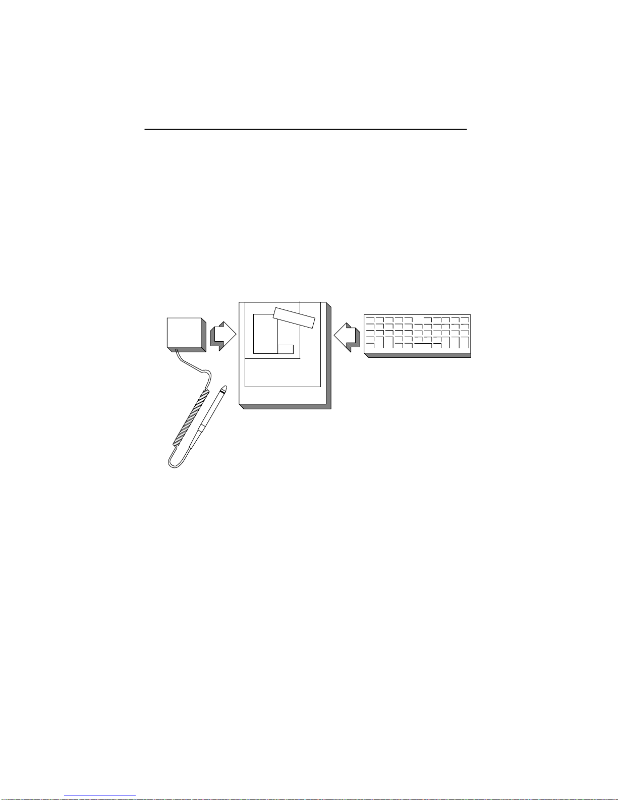
In this configuration the SCANTEAM 2000 provides a transparent
interface between the keyboard and the keyboard input port of the terminal
or PC. Output data format from the decoder unit is programmed using a
bar code programming menu. When installed, bar code symbols decoded
by the SCANTEAM 2000 are translated to corresponding keyboard
keycodes and sent to the keyboard input port of the terminal or PC. Thus,
bar code data appears as if it had been keyed in at the keyboard.
Figure 1.2 illustrates the second connection scheme. The SCANTEAM
2000 is configured for direct connection.
T erminal
Keyboard
2000
Figure 1.2 Direct Connection
With the addition of optional field installable IC’s, the SCANTEAM 2000
supports IBM 4683 Port 17/5B/9B and RS–232 (“serial wedge”)
input/output capability.
SCANTEAM 2000 Hardware/Software Overview
1–3
Page 21

1.2.2 Serial Wedge Capability ( 2000/ C Only)
The SCANTEAM 2000/C may also be used as a serial wedge. In this
configuration the SCANTEAM 2000/C is hooked to both a terminal and a
host computer. The decoded information is displayed on the terminal and
gathered and disseminated on the host. For example, if, in a commercial
environment, bar code readers are used to gather production data, an
assembler may complete a job and indicate that the job is finished by
scanning the information using a bar code reader. The SCANTEAM
2000/C then decodes the information and sends it to a terminal on a
supervisor’s desk, and simultaneously, sends it to a host computer where
the job is registered as done, inventory counts are changed, and the master
schedule is updated.
The serial wedge capabilities are compatible with RS–232 levels, offering
programmable communication to the host, to the terminal, or to both.
When idle, the SCANTEAM 2000/C enables the loop through of both
T erminal TX, RX, and Host TX, RX. All lines are monitored before data
is transmitted to make dure that the data being sent through the 2000 will
not be corrupted. The 2000 does not support RTS/CTS handshaking and is
not capable of processing and receiving data.
The programmable serial wedge parameters are baud rate (300–19200 bps),
parity (odd, even, mark/none, space), data bits (7, 8), and output modes (T o
Host and T erminal, To Host, or To Terminal).
1.2.3 Cloning
The SCANTEAM 2000 Series wedge includes a cloning capability which
provides a way to re–program installed wedges from a “source” wedge.
This capability eliminates the need to use a PC for each download. You
would use the Flash E Prom software program at a terminal to download
the information to the SCANTEAM 2000 “source” wedge. The Flash E
Prom is a programmable/erasable ROM (Read Only Memory) which
enables you to download new interfaces and upgrades without opening the
decoder. The “source” wedge would then be used to program the
“destination” wedges.
Note: Some terminals and power supplies support only one wedge.
1–4
SCANTEAM 2000 Hardware/Software Overview
Page 22
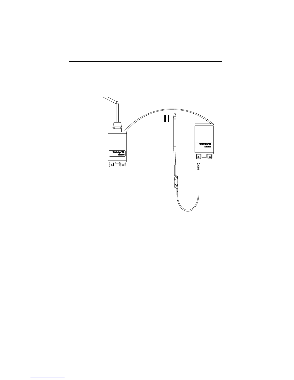
T erminal
“Destination”
Wedge
“Source”
Wedge
Figure 1.3 Cloning Example
Note: If you are using the cloning feature, make sure that the “source” wedge
is at the latest firmware revision level.
If you are going to use the cloning capability, make sure that the “source”
wedge is at the latest revision level of firmware. When you use the cloning
capability, you must make sure that the parity and baud rate of the
“destination” and the “source” are the same.
SCANTEAM 2000 Hardware/Software Overview
1–5
Page 23

After you check the parity, baud rate, and RS–232D chip compatibility, you
would scan the bar code below. The “source” wedge sends a Syn Del
Return message to the “destination” putting it in cloning mode.
Cloning Bar Code
Caution: DO NOT scan this bar code unless you are going to clone a
wedge. If you do, you will lock up your wedge and will have to
turn the power off and back on.
The “source” then sends 512 64 byte blocks of information followed by a
block check character. This takes approximately 20 seconds. When the
information has been downloaded to the “source,” ROM and RAM tests
are performed. If the cloning is successful in the 2000R, one beep will
sound. If the cloning is successful in the 2000C, two beeps will sound. If
the 2000 fails the ROM and/or RAM tests, you will hear three beeps (five
beeps if both tests fail).
The following figure illustrates the pin layout for the cloning cable.
1–6
1
2
3
4
5
6
Figure 1.4 Clone Cable Pin Layout
SCANTEAM 2000 Hardware/Software Overview
1
2
3
4
5
6
Page 24

1.2.4 Interface Cables/Connectors
The SCANTEAM 2000/R is configured for a particular interface by
connecting the correct interface cable. The unit supports OCR interfaces
with +5V only pull–ups in the host device. Higher voltage pull–ups may
damage the SCANTEAM 2000 output chips.
The SCANTEAM 2000/C is configured by scanning the proper terminal ID
from the Programming Menu and by connecting the proper interface cable.
The OCR, OCIA and RS–232D cable connectors on the terminal end vary
in connector type and pinout as determined by your equipment.
1.3 System Software Overview
1.3.1 Programmable Selections
The SCANTEAM 2000 can be programmed to autodiscriminate among the
following bar code symbologies and their variations: CODABAR, Code 3
of 9, UPC, EAN/JAN, Code 2 of 5, Interleaved 2 of 5, Code 93, MSI, Code
128, Matrix 2 of 5, Plessey, and Code 11.
The SCANTEAM 2000/R software is designed to support keyboards
equipped with either data entry or telephone style number pads, and is
capable of emulating keyboard function keys.
The SCANTEAM 2000/C software is configured to support data entry or
CTRL + keyboard configurations. Refer to page 6 of the SCANTEAM
2000 Programming Menu.
In addition to decoding selections, data output formats and auxiliary port
parameters are also menu programmable using the SCANTEAM 2000
scanning device.
1.3.2 Non–Volatile Memory
The SCANTEAM 2000 contains 512 bytes of non–volatile memory which
are used to store operating parameters programmed by means of the bar
code programming menu.
SCANTEAM 2000 Hardware/Software Overview
1–7
Page 25

An internal power monitor circuit resets the SCANTEAM 2000 hardware
when the nominal +5.0V operating voltage drops below +3.9V. A
software watchdog routine re–initializes the SCANTEAM 2000 if illegal
program execution occurs. A power monitor circuit is included to
re–initialize the SCANTEAM 2000 in the event a temporary power
interruption.
1.3.3 Memory Tests (2000/R ONLY)
When powered–up the SCANTEAM 2000 performs a ROM test and a
RAM test. A test failure causes the SCANTEAM 2000 to issue a single or
double beep sequence, respectively. A test of non–volatile memory
contents also is performed. If the SCANTEAM 2000 fails this test, it
issues a triple beep. Refer to T able 4.1 in Chapter 4, Programming the
Decoder for the beeper sequence and meaning.
1.4 Scanning Devices
The SCANTEAM 2000 is compatible with all Welch Allyn contact and
non–contact bar code scanners, including bar code contact wands, laser
guns, CCDs, and swipe readers. In addition, the product offers a dedicated
port for magnetic stripe scanning applications and supports “triple track”
scanning. Consult your Welch Allyn Sales Coordinator for specific model
numbers of compatible scanners.
1–8
SCANTEAM 2000 Hardware/Software Overview
Page 26
SYSTEM HARDW ARE DESCRIPTION
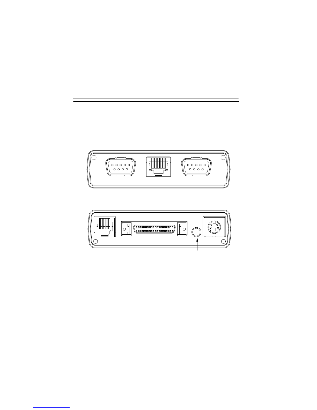
2.1 Decoder Unit
The SCANTEAM 2000 Decoder front and rear views are shown in Figure
2.1.
Front Panel
SCAN 1 MAG SCAN 2
Rear Panel
2
AUX INTERFACE PWR
LED Indicator
Figure 2.1 Front/Rear Panel Layout
SCAN 1 and SCAN 2 – Accepts 9 pin D–type, female, plastic,
squeeze–to–release connector. Compatible with all Welch Allyn wand,
CCD, or laser scanners.
MAG (Magnetic Stripe Reader) – Standard 8–pin modular connector.
This is a dedicated port for use only with a Welch Allyn one–, two–, or
three–track Magnetic Stripe Reader (MSR).
Hardware Description
2–1
Page 27

AUX (Auxiliary) – Standard 6–pin modular connector. Adds RS–232D
input/output capability to the SCANTEAM 2000.
INTERFACE – 40–pin high density connector. Universal port for
attaching the T erminal Interface Cable.
PWR (External Power Supply) – 4–pin, mini–din connector. For
SCANTEAM 2000 applications which require an external +5VDC power
supply .
2.2 Terminal Interface Cable
A single T erminal Interface Cable (depending upon decoder application) is
supplied with every SCANTEAM 2000 decoder. Interface cable options
and their associated part numbers are listed in Appendix C.
Keyboard Interface cables are custom fabricated for the designated
terminal/keyboard layout. They are properly terminated with all necessary
connector(s) to mate with the user terminals. The user end of T erminal
Interface Cables intended for OCR (SCANTEAM 2000/R),
OCIA(SCANTEAM 2000/R), and RS–232D applications varies in
connector type and pinout as required by your device.
2.3 Interface Port
The SCANTEAM 2000 Interface Port is a 40–pin high density connector
located on the back panel. This connector provides the signals necessary to
connect to and operate with the terminal. The output data format of the
Interface Port must be programmed before the decoder communicates
properly with the terminal.
The Interface Port is programmed using the Data Formatting Editor, the
Bar Code Chart, and Auxiliary Port Data Formatter pages in the
SCANTEAM 2000/R/C Programming Menu. Instructions for their use are
contained in Chapter 4, Programming the Decoder.
2–2
Hardware Description
Page 28

2.4 Auxiliary Port
2.4.1 Description
The SCANTEAM 2000 Auxiliary port is a 6–pin modular connector on the
rear panel of the decoder. It is only supported if the SCANTEAM 2000 is
equipped with an option chip configured for Aux RS–232D. The function
of this port is to transmit RS–232D data with RTS/CTS handshake and
receive the same according to the protocols outlined in Chapter 4,
Programming the Decoder.
The SCANTEAM 2000/R decoder must receive input data with the
following format: 1 Start, 7or 8 Data, 1 Parity, and 1 Stop Bit. The Aux
port can be programmed to operate at baud rates of 300, 600, 1200, 2400,
4800, 9600, 19200, and 38400 and with mark, space, even, odd, or none
parity. For proper operation the SCANTEAM 2000 must be programmed
for the same baud rate and parity as the connected RS–232D device.
The SCANTEAM 2000/R Aux Port is equipped with a buffer that holds up
to 256 characters. If an incoming message exceeds this length, the decoder
stores the extra characters by overwriting those characters stored at the
beginning of the buffer.
2.4.2 Basic Receive Operation
In the SCANTEAM 2000/R decoder data transfer is initiated when the
RS–232D device sends data. (Refer to Page 4–24 for 2000/C information.)
The SCANTEAM 2000 continues to receive and store data until receipt of
an End of Record Character.
The SCANTEAM 2000 lowers the CTS line and transmits the data to the
POS interface or terminal. Data is framed by the Preamble/Postamble if
preambles or postambles have been programmed. When all data has been
sent to the POS interface or terminal, the SCANTEAM 2000 raises the
CTS line causing the Aux Port to return to ready status. New Aux Port
data is now permitted. Refer to Chapter 4, Programming the Decoder, for
information on the operation of the 2000/C.
Hardware Description
2–3
Page 29

Aux Port data can be formatted according to the SCANTEAM 2000
terminal program requirements for keyboard interface applications using
the Data Formatter page in the programming menu. Instructions
concerning the formatting are contained in Chapter 4, Programming the
Decoder of this manual.
2.4.3 Transmit Operation
When RS232 Aux transmission is needed. select the terminal selection 00.
Data is sent with preambles and postambles if preambles/postambles are
programmed using valid ASCII characters (00–7F Hex).
2.5 Scanner Ports
The SCANTEAM 2000 features two scanner ports that are compatible with
all Welch Allyn industrial grade digital wand–type scanners, as well as the
Welch Allyn Model 5500 Series and 3000 CCD scanners. Some
non–Welch Allyn scanners may also be supported.
2.6 Magnetic Stripe Triple Track Reader (MSR) Port
The MSR port on the front panel of the SCANTEAM 2000 is dedicated to
the MSR 6900 magnetic stripe reader and is designed to accept undecoded
digital signals. T o process output from the reader, the MSR port must be
programmed through the scanner port using the programming menu. The
SCANTEAM 2000 MSR port cannot be programmed using the magnetic
stripe reader.
Data contained on bank credit cards and travel and entertainment cards
(i.e., American Express, etc.) as defined by ANSI are contained on tracks
1, 2, and/or 3 as shown in T able 2.1. The SCANTEAM 2000 user may
select either track as a source for data: (a) either track 1, 2, or 3; (b) tracks
1, 2, and 3; or (c) any one combination of the eight desired coding.
Specific instructions for programming the MSR port are discussed in
Chapter 4 of this manual and described in the SCANTEAM 2000
Programming Menu.
2–4
Hardware Description
Page 30

Track 1 Record Formats
Max. Record Length = 79 Char.
Length
1
*
* The length of these fields is card
issuer dependent.
** This is always the last 11 positions of Track 1, excluding the end
sentinel and Longitudinal Redundancy Check character.
Name of Field
Start Character (%)
Format Character1
Primary Acct Number13 or 16
Field Separator (^)1
Cardholder Name2–26
Field Separator (^)1
Card Expiration Date4
Service Code*
PIN Verification Field*
Discretionary Data
VISA Reserved*
Stop Character (?)1
LRC Character1
Track 3 Record Formats
Max. Record Length = 107 Char.
Length
1
2
Name of Field
Start Character (;)
Format Character
Primary Acct NumberUp to 19
Field Separator (=)1
Use & Security DataUp to 49
Additional DataUp to 33
End Character (?)1
LRC Character1
Track 2 Record Formats
Max. Record Length = 40 Char.
Length
1
*
*The length of these fields is card
issurer dependent.
Name of Field
Start Character (;)
Primary Acct Number13 or 16
Field Separator (=)1
Card Expiration Date4
Service Code*
PIN Verification Field*
Discretionary Data
Stop Character (?)1
LRC Character1
Table 2.1 Magnetic Stripe Triple Track Formats
Hardware Description
2–5
Page 31

2.7 Power Requirements
2.7.1 Keyboard Wedge Applications
When the SCANTEAM 2000 functions as a keyboard wedge, you may
choose to have the terminal supply power through the keyboard interface
connector. The SCANTEAM 2000 Decoder needs +5VDC +/–10% and
draws approximately 140 milli–Amps when connected to a terminal with a
wand scanning device. Power can come from an external power supply or
from the terminal to which the SCANTEAM 2000 is hooked. If you are
using an external power supply, you may need to change the internal power
jumper. See Figure 2.2 for jumper settings.
Jumper Settings
JP5
–12 VDC on pin 1
of Scan 2 Port
No connection
on pin 1 of
Scan 2 Port
Scan 1 Port
Mag Stripe Port
(2000 board with edge nearest beeper toward you.)
JP4
+12 VDC on pin 9
of Scan 2 Port
+5 VDC on pin 9
of Scan 2 Port
Power Supply Port
JP3
JP4
JP5
JP3
External
Power
Terminal
Power
Interface Port
Aux
Port
Beeper
2–6
Scan 2 Port
Figure 2.2 Power Configuration
Hardware Description
Page 32

RS–232D Auxilliary Port
The SCANTEAM 2000 can supply power to or be powered by a connected
device on the Aux Port with +5VDC available on pin 6.
Note: In many keyboard wedge applications, the terminal is capable of
supplying reasonably stable +5VDC power. The SCANTEAM 2000 has
a power monitor circuit which monitors the +5VDC line and shuts down
the microprocessor when voltage drops below +3.9VDC. When power
is not adequate or available, a +5VDC external power supply is
available.
Hardware Description
2–7
Page 33

2–8
Hardware Description
Page 34

SET–UP AND INSTALLATION
3.1 Preparation
The SCANTEAM 2000 Decoder and its associated components, including
scanning devices and interface cables, are bulk shipped in individual
corrugated cartons. Upon receipt, you should open each carton and check
the contents and part numbers to confirm that each item on the packing list
has been supplied in the proper quantity.
You also should thoroughly inspect the contents for possible shipping
damage. Any damage to components should be reported immediately to
the carrier which delivered the shipment. Damage claims due to handling
during shipping should be placed directly with the carrier.
T o assure proper operation and prevent possible damage to the
SCANTEAM 2000 decoder or terminal, you should perform the following
installation procedures in the sequence in which they are presented.
3
3.2 Set–up Procedure
Caution: The SCANTEAM 2000 contains static sensitive components.
Precautions must be taken to eliminate potential static discharge
to any printed circuit board. The SCANTEAM 2000 is configured
to support 5 volt lasers. However, you should be aware of the
following precautions when installing the 2000/C. (The 2000/R
set–up procedures follow the 2000/C set–up procedures.)
3.2.1 2000/C Set–up
(1) Turn off the power to the terminal to which the 2000/C will be
connected.
Set–up and Installation
3–1
Page 35

(2) Attach the decoder to the terminal.
(a) Locate the “Y” interface cable shipped with the 2000/C and
verify that it is the correct number. Cable part numbers are
provided in Appendix D.16 and on the page facing the T erminal
Selection instructions in the SCANTEAM 2000 Programming
Menu.
The general “Y” Interface Cable connections are illustrated in
Figure 3.1.
B
A
Figure 3.1 “Y” Interface Cable
C
3–2
(b) Plug the 40–pin male connector (A) of the Y” interface cable
into the 40–pin female connector located on the back panel of
the 2000/C until it clicks into place.
(c) Disconnect the keyboard from the terminal (display) and insert it
into the mating connector on the short leg of the “Y” interface
cable (B).
Set–up and Installation
Page 36

(d) Complete the cabling procedure by inserting the remaining long
leg of the “Y” interface cable (C) into the terminal keyboard
connector. (Connector from which the keyboard cable was
removed.)
(3) Position the 2000/C so that all cables run freely and smoothly. If
desired, the decoder can be secured to the terminal cabinet or table top
using the mounting strips supplied with the unit.
(4) Attach the scanning device(s) into the appropriate front panel
connector on the 2000/C. The scanning device cable will click into place
when properly seated in the connector port.
(5) Confirm the SCANTEAM 2000/C power supply rating. The 2000/C
can be ordered with one of several optional external power supplies,
depending upon user requirements. Inspect the rating plate on the power
supply module and the rating plate that is attached to the bottom of the
decoder. Confirm that the power supply provides the required operating
values.
(6) Connect the external power supply (if required). Make sure that the
external power supply is not connected to an AC power source. Install the
external power supply (if it is required) by plugging the 4–pin male DIN
output connector of the power supply into the 2000/C port labeled,
POWER, located on the back panel of the decoder.
(7) If an auxiliary RS–232D input/output device is to be used, plug the
6–pin modular plug of the auxiliary port cable (specified at the time of the
order) into the 6–pin modular socket on the back panel of the 2000/C until
it clicks into place. Connect the other end of the cable to the RS–232D
input device.
(8) When the 2000/C is fully connected, reconnect main AC power to the
terminal. If an external power supply is required, follow the steps below.
(a) Plug the external power supply into the appropriate line voltage
source. The green LED power indicator on the back panel of the
2000/C should light. The wedge issues two beeps.
Set–up and Installation
3–3
Page 37

(b) Turn on the terminal power. Do not try to enter data until the
host terminal has fully initialized.
If an external power supply is not needed, simply turn on the terminal
power. The green LED power indicator on the back panel of the 2000/C
should light. The wedge should issue two beeps. Do not try to enter data
until the host terminal has fully initialized.
3.2.2 2000/R Set–up
(1) When you install a keyboard wedge interface cable, turn off the system
power.
(2) Keyboard Wedge Applications
(a) Check the cable name/part number on the Keyboard Interface
Cable and confirm that it is the proper cable for your terminal.
Install the keyboard interface cable in your terminal using the
procedures listed in Appendix C.
Note: Although other installation techniques may be used, we strongly
suggest you follow the step–by–step instructions provided for your
particular terminal. These procedures have been developed and
tested by Welch Allyn engineers.
(b) When the terminal end of the interface cable has been installed,
plug the 40–pin high density connector of the interface cable
into the 40–pin high density connector labeled INTERFACE on
the SCANTEAM 2000.
3–4
Set–up and Installation
Page 38

HRL 5510 Laser
Interface Cable
40 Pin Connector
Scanner
Welch Allyn SCANTEAM 2000
8 Pin Modular Connector
MSR
(Magnetic Stripe Reader)
Figure 3.2 SCANTEAM 2000 Connections
(3) Plug the scanning device, either a CCD scanner, moving beam laser, or
hand held wand into the 9–pin male squeeze D connector labeled SCAN 1
or SCAN 2.
(4) Attach the Magnetic Stripe Reader (MSR) if one is being used. Plug
the reader into the 8–pin modular connector labeled MAG.
(5) If an auxiliary RS–232DC input device is to be used, plug the
connector of the Aux port cable into the connector labeled AUX. Connect
the other end of the cable to the RS–232D input device.
(6) Turn the power on the terminal. The green LED power indicator on
the rear panel of the SCANTEAM 2000 should light, and the unit should
issue a single beep.
Set–up and Installation
3–5
Page 39

This completes set–up and installation of the SCANTEAM 2000 Decoder.
You are now ready to configure the unit for your particular application.
Instructions for configuring the SCANTEAM 2000 using the Programming
Menu are provided in Chapter 4, Programming the Decoder.
3–6
Set–up and Installation
Page 40

PROGRAMMING THE DECODER
Before the SCANTEAM 2000 decoder can be placed in operation, it must
be programmed for the particular application by scanning bar code symbols
from the Programming Menu. The information and data format
instructions are stored in non–volatile memory when the programming
session is exited.
4.1 Beeper Sequence and Meaning
The table below lists the number and the meaning of the beeps your
decoder emits.
Sequence Meaning
1 Beep Valid bar code, mag stripe, or
RS–232D input; successful power–up
(2000/R).
2 Beeps Successful enter into and exit out of
Programming Mode; successful
power–up (2000/C).
3 Beeps Invalid bar code or program entry,
mag stripe, or RS–232D input.
4
3 beeps Fail ROM test on power up. (2000/R)
3 beeps Fail RAM test on power up. (2000/R)
5 beeps
Table 4.1 Beeper Sequence and Meaning
Programming the 2000 Decoder
Fail ROM and RAM test on power up.
(2000/R)
4–1
Page 41

4.2 The Programming Menu
The Programming Menu is divided into nine main sections: (1) T erminal
Selection, (2) Output Parameters, (3) Industrial Codes, (4) Retail Codes,
(5) Auxiliary Port, (6) Data Formatter, (7) Status Check, (8) the Bar Code
Chart, and (9) Code 3 of 9 Symbols.
Each section contains a menu page(s) which lists certain decoder
parameters and defines the scanning sequences for selecting specific
configuration options. A System Guide, in the beginning of the menu,
describes the programming menu page layout and identifies other helpful
information for the programming process.
4–2
Programming the 2000 Decoder
Page 42

4.2.1 Programming Menu Page
A typical programming menu page is shown in Figure 4.1.
3
scan
ENTER
scan
DEFAULT
4
SCANTEAM 2000 Programming Menu
USE THIS PAGE
1
To select the pre–programmed asterisked (*) values by scanning DEFAULT symbol.
To enable or disable listed code selections.
selections variables
2
UPC
ID = c
(HEX 63)
EAN
ID = d
(HEX 64)
UPC & EAN
ADDENDA REQ’D.
MSI
ID = g
(HEX 67)
PLESSEY
ID = n
(HEX 6E)
UPC/EAN ADDENDA
FORMAT
scan scan
Version A
Version D(4)
Version E0
Version E1
Check Digit Xmit
Number System Xmit
Version E Expand
2–Digit Addenda
5–Digit Addenda
EAN/JAN 13
EAN/JAN 8
Check Digit Xmit
2–Digit Addenda
5–Digit Addenda
Enable Yes/No*
Enable
Minimum Length
Maximum Length
Enable
Minimum Length
Maximum Length
With space *Yes/No
SELECTION II
CODE
(RETAIL)
scan
*Yes/No
A
B
C
D
E
F
G
H *Yes/No
I
A
B
C
DE*Yes/No
A
B
A
B
No*
*Yes/No
*Yes/No
%Yes/No#
%Yes/No#
Yes/No*
*Yes/No
*Yes/No
*Yes/No
%Yes/No#
*Yes/No
#Yes/No%
*04–Max
Min–48*
#Yes/No%
*04–Max
Min–48*
5
scan
EXIT
Notes:
(1) * Designates DEFAULT selections for the 2000/C and 2000/R.
6
(2) # Designates DEFAULT 2000/C selections.
(3) % Designates DEFAULT 2000/R selections.
(4) UPC Version D is not supported at this time.
Figure 4.1 Programming Menu Page
Programming the 2000 Decoder
4–3
Page 43

All of the SCANTEAM 2000 programming menu pages follow a similar
layout and contain the same basic programming elements.
(1) A “USE THIS PAGE” statement indicates the general programming
capabilities which appear on that menu page.
(2) The SELECTIONS/VARIABLES table lists primary programming
selections, variables which can be used to modify the basic selection,
and the bar code scanning sequence that must be used to configure the
decoder to these values.
Three discrete bar code commands allow global menu selections and
control movement between menu pages.
(3) Scanning the ENTER command bar code symbol activates that
particular menu page. The ENTER code for each menu page is
unique, and must be scanned before configuring commands from that
page will be recognized by the decoder.
(4) A generic DEFAULT command causes the Selection/Variables on the
activated menu page to automatically default to those values marked
by an asterisk (*). If a selection applies only to the 2000/C, the
option contains a “#.” If a selection applies only to the 2000/R, the
option contains a “%.” The “*,” “#,” and “%” signs are used as
indicators to distinguish the defaults. Do not scan these symbols.
(5) The common EXIT command terminates programming on the active
menu page. The EXIT symbol must be scanned before moving to
another page of the programming menu.
Information regarding special bar code applications is often provided at the
bottom of menu pages.
(6) This includes the special NOTES which are used to explain unusual
programming requirements and/or refer you to necessary information
or examples elsewhere in the menu or the SCANTEAM 2000 manual.
Additionally, the facing page for each programming menu is frequently
used to supplement or clarify material presented on the front of the menu
page. It may contain charts, diagrams, or detailed programming
instructions.
4–4
Programming the 2000 Decoder
Page 44

4.2.2 The Bar Code Chart
The SCANTEAM 2000 Bar Code Chart is shown below in Figure 4.2.
SCANTEAM 2000 Programming Menu
USE THIS PAGE
In combination with the adjoining menu pages to program the 2000.
The bar codes on this page correspond to symbols in shaded areas on adjoining menu pages. SCAN these bar
codes in the sequence indicated on menu page to program desired selections and variables.
BAR CODE CHART
ROMAN NUMERALS LETTERS DIGITS OTHERS
I
XI
II
XII
III
XIII
IV
XIV
V
A
0 (YES)
B
1 (NO)
C
2
D
3
E
ESCAPE
DEFAULT
EXIT
ALT–A
VI
VII
XV
F
XVI
G
XVII 6
Figure 4.2 Bar Code Chart
Programming the 2000 Decoder
4
ALT–B
5
ALT–C
4–5
Page 45

Note that symbol groupings include ROMAN NUMERALS, DIGITS,
LETTERS as well as discrete YES, NO, and EXIT symbols. The sequence
in which these symbols are scanned produces the programming commands
that enable or disable specific decoder functions.
Note: The bar codes must be scanned through the SCANTEAM 2000 Scanner
Port; the decoder cannot be configured using the magnetic stripe reader
or RS–232D input device. A Welch Allyn wand scanner is best for this
purpose.
4.3 Recommended Programming Sequence
The SCANTEAM 2000 operating parameters can be programmed in any
order by moving from one menu page to another. However, since the
programming process typically requires numerous scans, it is
recommended that you plan and document each configuration command in
advance. The following sequence is recommended for programming
decoder parameters:
STEP 1) TERMINAL SELECTION
STEP 2) OUTPUT Parameters
STEP 3) CODES (Industrial)
STEP 4) CODES (Retail)
STEP 5) AUXILIARY PORT
STEP 6) DATA FORMATTER
After you complete the programming process, use the STATUS CHECK
page in the Programming Menu to verify your settings.
4–6
Programming the 2000 Decoder
Page 46

4.4 Terminal Selection Menu Page
The Terminal Selection page of the Programming Menu is used to
configure the decoder for operation with a specific terminal device, or to
instruct the decoder to output data through the RS–232D Aux port. No
default parameters are included on this menu page. All terminal selections
must be programmed using the bar code chart at the end of the
Programming Menu.
In addition to identifying the proper selection/variable combination, the
correct “Y” interface cable must be installed. A table showing
terminal–to–part number relationships is provided in Appendix D and on
the Information & Examples page facing the T erminal Selection section of
the Programming Menu. Cable installation procedures are described in
section 3.0 of this manual.
Example: Configure the SCANTEAM 2000 TERMINAL SELECTION to the
following values:
T erminal: IBM PC/AT
(Refer to the Selections/Variables table on the TERMINAL SELECTION
page of the Programming Menu.)
Program these operating parameters following the scanning sequence
below .
FUNCTION SELECTION VARIABLE
Enter Menu Page ENTER
Enable IBM PC/AT 0
3
Leave Menu Page EXIT
Scanning the EXIT symbol stores the terminal type (IBM PC/AT)
information in non–volatile memory. This parameter will not have to be
programmed again unless the SCANTEAM 2000 is connected to a
different terminal type.
Programming the 2000 Decoder
4–7
Page 47

4.5 Output Parameters Menu Pages
The Output Parameter Menu pages of the programming menu is used to
configure beeper volume and tone, enable an inhibit check function,
specify that a secondary keyboard type is being used, and set intercharacter
and intermessage delays. An explanation of programmable selections
follows.
Beeper Volume/Tone
The volume of the audible signal used to indicate a “good read” and to
communicate other beeper sequences is programmable. The beeper
volume range is 00 – FFFF. You may silence the beeper (by programming
“00”), or select another value to obtain a sound level to meet your work
environment needs. You must scan once for volume and again for tone.
The tone of the beeper signal ranges from 00 – FFFF. No tone = 00; the
highest tone = equals FFFF. The following list presents suggestions for
high, medium, low, and off: high = 1919, medium = 4949, low = 0C0C,
and off=0000. Feel free to experiment with the beeper/tone setting to
determine an appropriate range for your environment.
Keyboard Style
This menu selection allows you to program the decoder to support special
keyboard features such as CAPS LOCK, SHIFT LOCK, Data Entry, and
CTRL + codes (e.g., CR, CTRL +“M.”) The facing page of the Output
section of the Programming Menu (page 4) lists the keyboard style options
for the SCANTEAM 2000.
Keyboard Layout III (Keypad) (SCANTEAM 2000R ONLY)
The Keyboard Layout option allows you to program the decoder to
transmit the proper keycodes when interfacing with a telephone, calculator,
or PC/AT–type numeric keypad layout. If your terminal only has a
numeric keypad and it is set up in a telephone keypad layout, enable the
telephone keyboard layout (Layout 1). If your numeric keypad is set up
like a calculator, enable the calculator keyboard layout (Layout 2). If your
terminal is equipped with a fully populated alphanumeric keyboard, use
Layout 3.
4–8
Programming the 2000 Decoder
Page 48

4683 I/O Port Selection (SCANTEAM 2000/R ONLY)
This menu selection permits you to specify the type of input port of an
IBM 4683 POS terminal to which the SCANTEAM 2000 should respond.
Unless programmed otherwise, the SCANTEAM 2000 defaults to accept
signals from Port 5B. The other options are Port 9B and Port 17.
OCIA Format Selection (SCANTEAM 2000/R ONLY)
This menu selection allows you to specify the type of output OCIA format
to which the SCANTEAM 2000 should respond. Unless programmed
otherwise, the SCANTEAM 2000 defaults to accept signals from NCR
“S.” The other options are NCR “F,” Nixdorf, and Spectra Physics.
OCR Format Selection (SCANTEAM 2000/R ONLY)
The OCR Format Selection allows you to specify the type of OCR input
port to which the SCANTEAM 2000 should respond. Unless programmed
otherwise, the SCANTEAM 2000 defaults to accept signals from Fujitsu.
The other option is IBM.
Intercharacter Delay
Intercharacter delay is the time delay between data characters output by the
SCANTEAM 2000. The delay is in x5 milliseconds, and you may set the
value to between 0000 and 9999 (x5ms).
Interfunction Delay
Interfunction delay is the time delay between function key characters
output by the SCANTEAM 2000. The delay is in x5 millisecond. You
may select any value between 0000 and 9999 (x5ms).
Intermessage Delay
Intermessage delay is the time delay between messages/records output by
the SCANTEAM 2000. The delay is in x5 milliseconds. You may set the
value to between 0000 and 9999 (x5ms).
Programming the 2000 Decoder
4–9
Page 49

4.5.1 Output Parameters Continued
Preamble
Preambles are assigned to a particular symbology using the SCANTEAM
2000 Series Programming Menu. When the preamble selection is enabled,
one or more characters are transmitted as a header immediately preceding
scanned bar code data. Any combination of ASCII characters or function
codes can be programmed. Preamble characters will be transmitted in the
order in which the selections were made. The preamble can be returned to
“none” by selecting Preamble and then selecting the symbology, scanning
FF and EXIT. A total of all of the preambles and postambles is limited to
40 characters.
Postamble
Postambles are programmable data identifiers which follow the bar code or
keyboard messages. Postambles are assigned to a particular symbology
using the SCANTEAM 2000 Series Programming Menu. Any
combination of ASCII characters or function codes may be programmed.
The postamble can be returned to “none” by selecting Postamble and then
selecting the symbology, and scanning FF and EXIT. A total of all of the
preambles and postambles is limited to 40 characters.
Note: The SCANTEAM 2000 translates characters 01–1F (keyboard function
codes) into keyboard function keys. The assigned translation is
dependent upon the terminal being used. Refer to Appendix D for
additional information about the keyboard function relationships.
Buffer Scans
If the Buffer Scans option is set to Yes, the decoder can accept a second
scan while it is outputting the current scan. If Single Scan is selected, the
decoder cannot accept additional scans until the current scan is outputted.
The default is Yes for the 2000/C and No for the 2000/R.
Input Inhibit Check (SCANTEAM 2000/C ONLY)
In most terminal environments, the terminal is often “inhibited” from
sending data to the host CPU if the CPU is engaged in a certain data
processing activity. Input inhibit originates at the CPU and most likely
occurs immediately after a screen, or page of data is sent to the host CPU
or when the operator activates the “XMIT,” “SEND,” or “ENTER” key at
the terminal keyboard. As long as the “inhibit” signal is present, further
input from the keyboard is ignored by the terminal.
4–10
Programming the 2000 Decoder
Page 50

In many bar code data collection systems the Input Inhibited condition is
communicated to the operator on the terminal screen. However, since the
SCANTEAM 2000 can emulate the operator’s action of sending data to the
host CPU which could generate an Input Inhibit condition, the Input Inhibit
condition must be monitored by other than visual means if available.
That is the purpose of the Input Inhibit Check menu selection. When Input
Inhibit Check is enabled, the monitoring function is performed
automatically by the decoder. The SCANTEAM 2000 continually checks
for the Input Inhibit signal and will not attempt to transmit data as long at
the inhibit option is present.
SPECIAL IBM 3178 PROGRAMMING NOTE (SCANTEAM 2000/C ONLY):
If the Input Inhibit capability is to be used in conjunction with an IBM
3178 terminal, the SCANTEAM 2000 Input Inhibit feature must be
enabled, and the 3178 Key Click should be turned OFF. Proper operation
can be confirmed by making sure the terminal only clicks when it is in the
input inhibited state.
Code ID Transmit
When this menu selection is enabled the decoder transmits a single lower
case ASCII character to identify which symbology was decoded. For
example, Code 3 of 9 is identified by a lower case “b,” while Code 128 is
identified by a lower case “j.” The default is No.
The code identifier for each bar code symbology is listed below and
appears immediately following the symbology name on the Symbology
Selection Menu Page.
SYMBOLOGY CODE ID
CODABAR a
Code 3 of 9 b
UPC c
EAN d
Interleaved 2 of 5 e
Code 2 of 5 f
MSI g
Code 1 1 h
Code 93 i
Code 128 j
Matrix 2 of 5 m
Plessey n
Programming the 2000 Decoder
4–11
Page 51

Function Codes
When this menu selection is enabled, and function codes are contained
within the scanned data, the SCANTEAM 2000 transmits the key code to
the terminal which corresponds to the decoded ASCII function code.
ASCII function codes are represented by the HEX values (00–1F).
When the Function Codes selection is disabled, the decoder does not
transmit the key codes which correspond to the HEX characters 01–1F
unless they are in preambles or postambles. Instead, the characters 01–1F
are stripped from the bar code data. Any keyboard function codes in the
scanner port preamble and postamble will be sent to the terminal regardless
of the parameter. Function codes in preambles and postambles are
automatically translated to key codes.
Note: Care should be taken not to embed keyboard function codes that will
cause an input inhibit condition within records, preambles, and
postambles. Attempts to embed function codes may result in loss of
data.
Example – Keyboard Function Codes (Commercial Application):
The SCANTEAM 2000 is connected to an IBM PC; Keyboard Function
Codes within data and the Preamble and Postamble on the continuation
page of the Output section of the Programming Menu.
The SCANTEAM 2000 is programmed as follows:
Preamble: GS (1D)==>F10 key
Postamble: CR (OD)==>ENTER key
Full ASCII Code 3 of 9 Decoding: enabled
Note: When programming preambles and postambles you must scan a
symbology before scanning in a scan code.
Consider the case of a Code 3 of 9 bar code symbol:
1 2 3 4 “HT” 5 6 7 8
The function emulated depends not only upon the Keyboard Function
Code, but also upon the terminal being used with the SCANTEAM 2000.
Appendix D lists, by terminal type, the key function emulated by each
Keyboard Function Code. (The codes in the center column change.)
4–12
Programming the 2000 Decoder
Page 52

CASE 1 – Function Codes “Enabled”
With the Scanner Port Function Codes enabled, the SCANTEAM 2000
outputs 1234HT5678 to the terminal as:
F10 1 2 3 4 “TAB ”5 6 7 8 ENTER
preamble postamble
Notice that Keyboard Function Code, HT, has been translated and sent as
the TAB key .
CASE 2 – Function Codes “Disabled” (Commercial Application):
When the Scanner Port Function Codes are disabled, the SCANTEAM
2000 outputs 1234HT5678 to the terminal as:
F10 1 2 3 4 5 6 7 8 ENTER
Notice now that HT has been stripped from the data string. Note also, that
Keyboard Function Codes contained within the Preamble and Postamble
(F10 and ENTER) are not affected by the Scanner Port Function Code
selection (IV) and so they are translated and sent.
Keyboard Function Records
Keyboard Function Records are special incoming data records which can
originate from either the Aux Port or the Scanner Port.
Keyboard Function Records are translated by the SCANTEAM 2000 and
sent to the terminal as keyboard function keys. The function which is
emulated depends upon both the Keyboard Function Record and the
terminal selection. The key functions emulated by each Keyboard
Function Record are listed according to terminal type in Appendix Section
C.1 to C.15.
Keyboard Function Records differ from Keyboard Function Codes in the
following ways:
(1) Keyboard Function Records cannot be disabled by menu
programming.
(2) Keyboard Function Records cannot be embedded within other
Aux Port or Scanner Port data; they are stand alone records, and
if embedded, will be treated as normal data.
Programming the 2000 Decoder
4–13
Page 53

(3) When Keyboard Function Records are entered, any
Preambles/Postambles which may have been programmed will
not be added to the output transmission.
Example – Keyboard Function Records (Commercial Application)
The following examples illustrate the effect of Keyboard Function Records
on data transmission when used in conjunction with the Scanner Port and
the Aux Port.
Scanner Port Data
In this example the SCANTEAM 2000 is connected to an IBM PC, and the
function key F10 is to be emulated using a Keyboard Function Record
entered via the Scanner Port. The symbology Full ASCII Code 3 of 9 has
been enabled.
When configured in this way, scanning a Code 3 of 9 label containing the
following characters:
/ C 3 1
will produce a decoded output of (#31).
The SCANTEAM 2000 translates this scanner output (#31) and sends the
designated Keyboard Function Record (F10) to the terminal. (Refer to the
Keyboard Function Record relationships listed in C.1 to C.17.)
OCIA and Wedge (SCANTEAM 2000/R ONLY)
This function allows you to determine which output mode (OCIA or
wedge) in which the bar code and MSR data will be output.
IBM 4680 Dual Track MSR Track 1 and 2 (SCANTEAM 2000/R ONLY)
Enabling this selection causes the SCANTEAM 2000 to emulate an IBM
4680 dual track reader.
IBM 4680 Dual Track MSR Track 2 and 3 (SCANTEAM 2000/R ONLY)
Enabling this selection causes the SCANTEAM 2000 to emulate an IBM
4680 dual track reader.
4–14
Programming the 2000 Decoder
Page 54

Wand/Laser Port Modes
Laser Timeout
When Laser Timeout is enabled, the SCANTEAM 2000 turns off power to
the laser scanner 4 seconds after the trigger has been pulled and a valid
decode is not accomplished. Power to the laser is not restored until the
trigger is released and pulled again. If the timeout selection is not enabled,
the laser may not turn off until the trigger is released (depending upon the
laser manufacturer and configuration). If the laser does not turn off, the
scanning may continue until a valid scan is obtained.
Laser Redundancy
When this selection is enabled, the SCANTEAM 2000 requires three (3)
consecutive and identical decodes resulting from a laser scan before issuing
a “good read” beep and transmitting the bar code data. When this function
is disabled, the “good read” will be issued and data is transmitted to the
terminal following one (1) valid scan.
Dual Wand
If you are using two wands, change this setting to Yes for improved
scanning response time.
Country Code (2000/C)
The SCANTEAM 2000/C re–maps the keyboard layout appropriately for
the selected country. Country Codes are listed below in Table 4.2 and
appear on the OUTPUT PARAMETERS II page of the Programming
Menu.
Programming the 2000 Decoder
4–15
Page 55

Country
Code
United States
Belgium
Denmark/Finland/Norway/Sweden
France
Germany/Austria
Italy
Switzerland
United Kingdom
Denmark (WYSE 30, 60)
Norway (WYSE 30, 60)
Spain
00 (Default setting)
01
02
03
04
05
06
07
08
09
10
Table 4.2 Country Codes
As a general rule, the following characters are not supported by the
SCANTEAM 2000 for countries other than the United States:
@ | $ # ^ ‘{ } [ ] = / \ < > ~
Note: PC users may need to program an Intercharacter Delay of at least 1 X
5ms when a country other than the United States is selected.
The following example includes the scanning sequences needed to
configure the SCANTEAM 2000 Output Port/Beeper settings to the
following values.
Beeper Volume/Tone: Volume =10 Tone = 10 (This is a 4–digit
scan. The first two digits set the volume; the second two digits set the tone.
The default is 1919.)
Inhibit Input Check: Enable
T erminal: IBM PC/XT
Keyboard: CAPS LOCK (Secondary Keyboard)
Intercharacter Delay: 10ms (2x5ms)
Interfunction Delay: 50ms (10x5ms)
Intermessage Delay: 10ms (2x5ms)
4–16
Programming the 2000 Decoder
Page 56

The scanning sequence to program these operating parameters would be:
FUNCTION SELECTION VARIABLE
Enter Menu Page ENTER
Set DEFAULT Values DEFAULT
Set Beeper Volume/Tone I
T o level “1010” 1
0
1
0
Specify Secondary (CAPS LOCK)
Keyboard II
B
Set Intercharacter Delay VII
T o 10 milliseconds 0
0
0
2
Set Interfunction Delay VIII
T o 50 milliseconds 0
0
1
0
Set Intermessage Delay IX
T o 10 milliseconds 0
Leave Menu Page EXIT
(Refer to the Selections/Variables options on the OUTPUT Parameters
pages in the SCANTEAM 2000 Programming Menu.)
Programming the 2000 Decoder
0
0
2
4–17
Page 57

4.6 Code Selection I (Industrial) Menu Page
The SCANTEAM 2000 autodiscriminates between the following Industrial
symbologies: CODABAR, Code 3–of–9, Interleaved 2 of 5, 2–of–5, Matrix
2 of 5, Code 11, Code 93, Code 128, and Code 16K.
All codes can be disabled or enabled via the programming menu. When a
code is disabled, the unit ignores any scans of that particular code. No
error signal (beep) is issued. Menu selection XIX allows you to disable all
codes, including retail codes. Available Industrial codes and their options
are listed in T able 4.3.
Code
Symbology
CODABAR
Code 3 of 9 00 Full ASCII, symbol
Length
Min Max
01 Concatenation
60
Options
48
appendation, check character
transmission
I 2 of 5 02 80 Check digit, check digit
(even #’s only) transmission
2 of 5 01 48 None
Matrix 2 of 5 01 80 None
Code 11 01 80 1 or 2 check digits required
Code 93 00 64 None
Code 128 00 80 EAN-128 Programming
ISBT None
Code 16K 00 154 Function character
transmission
Table 4.2 Industrial Codes
Decoding Algorithm
Decoding algorithm will select the decoding aggressiveness of the 2000/C
decoder. The Adaptive style is a more forgiving type of decoding and will
be “snappier” when it is decoding, allowing decoding of bar codes that are
consistently out of tolerance and do not conform to the symbology
specifications. The Traditional style will ensure correct decoding and not
allow any variances from the normal bar code specification. This menu
selection applies to Codabar, Code 39 and Interleaved 2 of 5 symbologies.
4–18
Programming the 2000 Decoder
Page 58

Example: Configure the SCANTEAM 2000 to decode the following
symbologies:
Code 39: Maximum Length = 14
Minimum Length = 8
Start/Stop: Transmit
Check Digit: Required
Check Digit: Transmit
Full ASCII: Yes
Code 128: Maximum Length = 12
Minimum Length = 6
Refer to the Selections/Variables options on the CODE Selection I
Industrial page of the Programming Menu.
Note: If Check Digit is required and the code does not contain a check digit,
the SCANTEAM 2000 will not read the code.
The scanning sequence to program the decoder to read these Code 39 and
Code 128 formats would be:
FUNCTION SELECTION VARIABLE
Enter Menu Page ENTER
Set DEFAULT Values DEFAULT
Set Code 3 of 9 II
Set Minimum Length A
To 8 0
8
Set Maximum Length B
To 14 1
4
Programming the 2000 Decoder
4–19
Page 59

Set Start/Stop Characters C
To Transmit Yes
Set Check Char Required D
T o Required Yes
Set Check Digit E
To Transmit Yes
Set Full ASCII F
T o enabled Yes
Set Code 128 VIII
T o enabled Yes
Set Minimum Length A
To 6 0
6
Set Maximum Length B
To 12 1
2
Leave Menu Page EXIT
(1)
– To maximize reading ef ficiency and security, all unused codes should
be disabled.
Code 3–of–9 may have the “append” function enabled or disabled with the
programming menu, whereas the Code 128 “append” function cannot.
4–20
Programming the 2000 Decoder
Page 60

4.7 Code Selection II (Retail) Menu Page
The SCANTEAM 2000 autodiscriminates between the following Retail
symbologies: UPC, EAN, MSI and Plessey and their variations. All codes
can be disabled or enabled via the programming menu. When a code is
disabled, the unit ignores any scans of that particular code, and no error
signal (beep) is issued. Available Retail codes and their options are shown
below in T able 4.4.
Code
Symbology
UPC
Length
Min Max
Options
Not Selectable Enable V ersion (A, E), V ersion
E output compressed or expanded, 2 or 5 digital addendum, check digit transmission,
number system digit transmission.
EAN/JAN Not Selectable
Enable V ersion 8 and 13, 2 or
5 digit addendum, check digit
transmission ISBN conversion.
UPC & EAN Addenda Required Y es or No
UPC & EAN Addenda Format Space/No Space
Code MSI 04 48 None
Plessey 04 48 None
Table 4.4 Retail Codes
A code with an incorrect check character is ignored (i.e., it is treated as a
disabled code). The check character for all applicable codes may be
transmitted or not, depending on the menu selection made. UPC Version E
may be transmitted as an expanded code (i.e., with zero’s inserted or in its
compressed state as shown in the human readables).
Programming the 2000 Decoder
4–21
Page 61

For example, consider the decoded UPC–E data message 078349. The
number system digit and check digit transmissions are disabled. When the
“compressed” option is enabled, data will be transmitted as 078349.
If the “expanded” option (Version E Expand) is enabled, the same data
message will be transmitted as 0783400009.
In order to assure highest reading accuracy, all unused codes which do not
default to the disabled state should be disabled. Since the codes MSI and
Plessey default to disabled status, it is not necessary to program these codes
to a disabled state.
Example: Configure the SCANTEAM 2000 to the following retail code
symbologies and values:
UPC–A will be sent with the following properties:
Check Digit Xmit Disabled
# System Digit Disabled
2–digit Addenda Disabled
5–digit Addenda Disabled
Read UPC Version E (expanded)
Refer to the Selections/Variables table on the CODES RETAIL menu page.
The scanning sequence to program the decoder to read only this UPC Code
format would be:
FUNCTION SELECTION VARIABLE
Enter Menu Page ENTER
Set DEFAULT Values DEFAULT
Enable UPC–A I A
Yes
Enable UPC Version E 0 C
Yes
4–22
Programming the 2000 Decoder
Page 62

Enable UPC Version E 1D
Yes
Disable Check Digit Xmit E
No
Disable # System Xmit F
No
Enable UPC–E Expanded G
Yes
Disable 2–digit Addenda H
No
Disable 5–digit Addenda I
No
Disable EAN II
Disable EAN/JAN 13 A
No
Disable EAN/JAN 8 B
No
Disable UPC & EAN III
Addenda Required No
Disable MSI IV No
Disable Plessey V No
Leave Menu Page EXIT
Note: To assure highest reading accuracy, all unused codes (EAN/JAN13,
EAN/JAN 8, MSI, and Plessey) were disabled.
Programming the 2000 Decoder
4–23
Page 63

4.8 Auxiliary Port
The AUXILIARY PORT menu page is used to configure the baud rate,
parity, data length,and protocol for the Auxiliary RS–232D Port.
Baud Rate
Baud rate is a means of expressing data transmission speed. The Baud rate
must match that of the device with which you are communicating. The
programming selection permits the user to specify any of the eight (8)
values including 300, 600, 1200, 2400, 4800, 9600, 19,200, and 38,400
baud.
Parity
Parity provides a means of checking character bit patterns for validity. The
Parity must match that of the device with which you are communicating.
The SCANTEAM 2000 can be configured to operate under odd, even,
mark, none, or space parity.
Data Length (2000/C)
Data Length presents a way for you to specify the system word length (7 or
8) in bits. The Data Length must match that of the device with which you
are communicating.
Protocol (2000/C)
A protocol is a set of rules concerning the exchange of data between
communicating devices. The SCANTEAM 2000/C supports Record,
Burst, and ACK/NAK protocols when receiving data from a RS–232D
device. In explaining these protocols, the terms Start of Record, End of
Record, Start of Block, and End of Block are used.
Start of Record Character (SOR) (2000/C)
The Start of Record Character is one of the characters 01h–7Fh that
indicates the start of a SCANTEAM 2000/C Aux Port data record.
End of Record (EOR)
The End of Record Character is one of the characters 01h–7Fh that marks
the end of a SCANTEAM 2000 Aux Port data record.
4–24
Programming the 2000 Decoder
Page 64

Start of BLOCK (SOB) (2000/C)
The Start of Block Character is one of the characters 01h–7Fh that
indicates the start of a block of data within a SCANTEAM 2000/C Aux
Port data block.
End of Block (EOB) (2000/C)
The End of Block Character is one of the characters 01h–7Fh that indicates
the end of a block of data within a SCANTEAM 2000/C Aux Port data
block.
Note: SOB, EOB, SOR, and EOR characters are not considered data, and,
therefore, are not sent to the terminal.
Record Protocol (2000/C)
When Record Protocol is enabled, the SCANTEAM 2000/C accepts a data
record of variable length up to a maximum of 253 characters including
preamble, postamble, and a one character delimiter. The incoming data
record must end with a EOR character that matches the EOR character
programmed into the SCANTEAM 2000/C. EOR characters are not sent
by the SCANTEAM 2000/C to the terminal. Any Auxiliary Port
Preamble(s) and Postamble(s) that have been programmed will be sent with
the record.
In Record Protocol, a Start of Record is optional. If an SOR is
programmed, the 2000/C does not start accepting data until the selected
SOR is detected. If an EOR is received before the SOR, the 2000/C emits
a beep indicating receipt of the EOR, but no preceding data is retained or
sent to the terminal.
The delimiter is a character reserved for internal use by the SCANTEAM
2000 to separate records stored in the output buffer.
In record protocol mode, each record is sent to the terminal as it is
received. RTS is deasserted by the SCANTEAM 2000/C between records
or when the buffer is full. Often a RS–232D sending device will transmit
one or two characters before it reacts to RTS inactive. The SCANTEAM
2000/C retains these characters (providing buffer space is available) and
will use them as the first two characters of the next record on the
convention that the sending device will continue sending data from the
point where it left off when RTS is reasserted.
Error conditions are signaled by a triple beep.
Programming the 2000 Decoder
4–25
Page 65

Burst Protocol (2000/C)
When programmed for Burst Protocol, the SCANTEAM 2000/C receives
data from a device “in bursts” (i.e., data that is not blocked by the sending
device). The maximum size of the burst is controlled by the SCANTEAM
2000/C. Unless an overflow condition exists, the maximum record size
with a burst is approximately 253 characters, inclusive of preambles,
postambles, record, and a one character delimiter.
The 2000/C strips data out of a burst one record at a time and sends the
data to the terminal until either of the following conditions occurs:
1) an EOB is received indicating the end of data; or 2) an error is detected.
If an error is detected, the 2000/C stops accepting data and discontinues
transfer of data to the terminal until an EOB is received. Then the 2000
emits an error beep.
Note: The delimiter is a character reserved for internal use by the SCANTEAM
2000 to separate records stored in the output buffer.
The SCANTEAM 2000/C allows for optional monitoring of SOR for each
record. A burst can contain one or more data record(s). The SCANTEAM
2000 also allows for optional use of a SOB character. Each data record
within a burst (of multiple record burst) must end with an End of Record
(EOR) character that matches the EOR character programmed in the
SCANTEAM 2000. The SCANTEAM 2000/C does not send the EOR
character to the terminal. The SCANTEAM 2000/C continues to accept
data until the buffer is filled or an End of Block character is encountered.
The sending device must assert CTS. Upon seeing CTS, the SCANTEAM
2000/C transmits a XON (DC1). (RTS is already asserted). The sending
device is now allowed to send.
The SCANTEAM 2000/C sends an XOFF (DC3) and deasserts RTS when
the SCANTEAM 2000/C buffer is full and requires servicing or an EOR or
EOB character is detected. The sending device is required to halt sending
until RTS and XON is reasserted.
4–26
Programming the 2000 Decoder
Page 66

ACK/NAK Protocol (2000/C)
The SCANTEAM 2000/C can be programmed to receive data in one of
two ACK/NAK protocols –– record mode or block mode.
Record Mode (2000/C)
When operating in Record Mode, the SCANTEAM 2000/C receives data in
single records. Each record may contain up to 253 characters including
preamble, postamble, and a one character delimiter. The delimiter is a
character reserved for internal use by the SCANTEAM 2000/C to separate
records stored in the output buffer.
A SOR character is optional in the SCANTEAM 2000/C Record Mode. If
programmed, data is not accepted until SOR is detected; the SOR is not
sent to the terminal.
The incoming data record must end with the same EOR character
programmed into the SCANTEAM 2000. The SCANTEAM 2000/C does
not send EOR characters to the terminal.
When a record is successfully received, the SCANTEAM 2000/C issues an
ACK (06) Hex to the RS–232D device. The device connected to the
Auxiliary Port is now allowed to send another record provided RTS is
asserted.
The SCANTEAM 2000 also asserts/deasserts RTS (Request To Send) as it
is able to accept/not accept data. If the SCANTEAM 2000/C deasserts
RTS, the sending device must stop transmitting or the data will be lost.
In Record Mode, if an error is encountered, the SCANTEAM 2000/C
sounds a triple beep, issues a NAK to the sending device, and deletes any
data relating to the corresponding record.
Programming the 2000 Decoder
4–27
Page 67

Block Mode (2000/C)
When Block Mode operation is selected, each data entry is transmitted on a
per line basis until a End of Block (EOB) is received from the sending
device.
The SCANTEAM 2000/C strips data out of a block one record at a time
and sends the data to the terminal until either of the following conditions
occurs:
1) an EOB is received indicating the end of data; or 2) an error is detected.
If an error is detected, the SCANTEAM 2000/C stops accepting data and
discontinues transfer of data to the terminal until an EOB is received. Then
the 2000 emits an error beep.
The SCANTEAM 2000/C issues an ACK to the auxiliary device upon
receipt of the EOB character.
If an error is encountered at any time during the transmission of the block,
the SCANTEAM 2000/C emits three beeps and issues a NAK. In this case,
the data from the point the error is detected is lost and must be transmitted.
When records are being transferred in Block Mode, Record Mode rules
apply to records contained within the block with regards to SOR, EOR, and
CTS. Refer to the previous discussions on SOR and EOR.
Function Codes (2000/C)
The SCANTEAM 2000/C translates the character HEX 01–1F (keyboard
function codes) that may be contained within Auxiliary Port records into
keyboard function keys. Function Codes are determined by the scanner
programming selection page. When the menu selection is enabled, these
function keys will be sent to the terminal along with the other characters in
the Aux Port record.
Function codes programmed in preambles and postambles are sent
regardless of scanner page selection.
4–28
Programming the 2000 Decoder
Page 68

AUX Port Signal Specifics
Use the following information to ensure the communications and
handshake lines of the interface cable are properly configured for use with
the selected sending device. The SCANTEAM 2000/C is configured as a
DTE (Data T erminal Equipment).
Tx – Output from the SCANTEAM 2000/C.
Rx – Input to the SCANTEAM 2000/C.
CTS – Input to the SCANTEAM 2000/C. CTS indicates a device is
present and is requesting to send data.
RTS – SCANTEAM 2000/C output used to indicate to the sending device
that it is clear to send. The SCANTEAM 2000/C deasserts RTS when it is
unable to accept data.
Solicit Mode (2000/C)
One–For–One
When enabled, the SCANTEAM 2000/C requests data from a device
connected to the AUX port after every barcode scan. The Solicit function
is accomplished by transmitting the data string programmed in the AUX
Port Solicit Message to the peripheral RS–232D device. The SCANTEAM
2000/C then waits for a fixed period of four seconds (timeout). If data is
not received from the peripheral device within this four second window,
the SCANTEAM 2000/C aborts the Solicit function and returns to normal
barcode input mode. Refer to Figure 4.3.
Programming the 2000 Decoder
4–29
Page 69

Scan Bar Code
Output To Terminal
Send Solicit Message To Peripheral
Abort
Wait (4 Seconds max)
Send AUX Data To T erminal
Figure 4.3 One–For–One Flow
Timeout
On Match
When a bar code input is matched to the character string programmed
using the Solicit On Match Code option, the solicit message is sent to the
Aux Port. The SCANTEAM 2000/C then waits for a fixed period of four
seconds. If data is not received within this four second time period, the
solicit function is aborted. The Aux data is then sent to the terminal. The
match code is not sent to the terminal. Refer to Figure 4.4.
4–30
Programming the 2000 Decoder
Page 70

Scan Barcode
No
Scan =
Match
String
?
Yes
Send Solicit Message To Peripheral
Timeout
Abort Wait (4 seconds max.)
Send AUX Data to Terminal
Figure 4.4 On Match Flow
Solicit Message
The solicit message is transmitted to the RS–232D device. The solicit
message may consist of any of the standard ASCII set (01–7Fh). The
exception is any ASCII character which would be in conflict with the
selected protocol, such as the use of ACK or NAK when ACK/NAK is
selected.
Programming the 2000 Decoder
4–31
Page 71

Solicit Match String
The solicit match string may consist of any of the standard ASCII set
(01–7Fh). The match string is compared to the incoming bar code data to
identify a “Solicit Aux Data” requirement.
CTS Check (Transmit) (2000/R)
This menu selection will enable the 2000/R to look at the CTS (Clear to
Send) line or disable the 2000/R from looking at the CTS line during data
transmission through the aux port only.
4.9 Data Formatting
The Data Formatter menu page is used to edit input data, scanned,
magnetic stripe, or serial AUX port input, prior to transmitting the data to
the host device. All of the Industrial and Retail Code symbologies listed in
sections 4.5 and 4.6 can be formatted.
Programming is accomplished by identifying the terminal type input source
and selecting the desired delimiters using the Keyboard Layouts provided
in the SCANTEAM 2000 Series Programming Menu.
4.9.1 Data Formatter
Format Required?
If this selection is set to the default (No), the data will be output to the host
as scanned (including preambles and postambles), and pre–edited formats
V–VI will be ignored. If Yes is selected, all input data must conform to an
edited format or the SCANTEAM 2000 will not transmit the input data to
the host device. The 2000 emits a triple beep indicating an error condition.
Note: If Format Required is enabled and a label is scanned that does not meet
the programmed format, the SCANTEAM 2000 emits three beeps and
rejects the label.
4–32
Programming the 2000 Decoder
Page 72

4.10 Data Formatter Editor Selections
Terminal Type Selections
Data Formatting applies to all SCANTEAM 2000 interfaces that require
data editing.
T erminals are identified and programmed by a two–digit terminal
identifier. The identifiers for the SCANTEAM 2000 are found on the
T erminal Selection page (page 3) of the SCANTEAM 2000 Series
Programming Menu. The retail identifiers are listed in the Keyboard
Wedge T erminal Type table that follows.
T ype
00
01
T erminal
AUX Port
NCR 2152
02 NCR 2151
03 IBM 3653
05 OCR
06 NCR 280
07 IBM 3683
08 IBM 4683
09
48
OCIA
NCR 7052
99 Universal
Table 4.5 Retail Keyboard Wedge Terminal Types
If you have several terminals using the same symbology, character length,
and format (editor command sequences), you may enter a terminal type of
99 (Universal). Entering a terminal type of 99 may prevent you from
programming a format for each terminal.
Programming the 2000 Decoder
4–33
Page 73

Retail Point of Sale Terminal Programming (“Plug and Play”)
*(2000/R Special Note)*
T o program the 2000/R for IBM 4683, OCIA and OCR “Plug and Play”
operation, scan the default bar code on the DATA FORMATTER page in
the 2000 Programming Menu. Upon defaulting the DATA FORMATTER
page, the decoder firmware will check the programming pins and/or the
terminal I.D., plus any other specific options to determine the desired
interface, and then set up the Data Formatter, preambles and postambles for
“plug and play” operation.
Code ID
The Code ID is a 1–character identifier which determines the source of the
input data being edited. The Code ID also identifies whether the format is
a primary format or one of three alternate formats. The Code ID identifies
the symbology of scanned data or the track number or mag stripe data or if
the input data is from the serial AUX port.
T o enter the Code ID refer to the Symbology Chart on page 4 of the
Programming Menu. Use the Primary column two–digit representations of
the desired symbology.
(1) Alternate Format Code (Alt. Form)
If the primary format for a particular input string of data must be altered
from time to time to satisfy a special application, an alternate format may
be programmed and enabled when needed. The Alternate Format selection
allows symbologies of the same type and length to be output on the same
terminal via a different format. For example, if you want to use ALT A for
Code UPC–A, scan 83. The alternate format is enabled by scanning the
ALT–A, ALT–B, or ALT–C barcode labels on the Bar Code Chart in the
SCANTEAM 2000 Programming Menu. If no alternate format is
specified, the primary (i.e., non–alternate format) will be used.
Note: Every time you require an alternate format, you must scan the
appropriate alternate format bar code symbol from the SCANTEAM
2000 Programming Menu.
4.10.1 Programming Example
The following example illustrates how the procedure described above
should be used with an alternative format.
4–34
Programming the 2000 Decoder
Page 74

Example: Alternate Format
T o provide a means of scanning an altered price tag, you must program an
Alternate Format selection.
The original selling price has been encoded into the barcode label and the
floor markdown was identified by crossing out the human readable price on
the label and handwriting the new price below it.
Therefore, the transaction becomes an Alternate Format purchase. Refer to
Figure 4.5.
DPT CLS STOCK
542 999 0001066
Field Length
#1 DEPT
#2 CLS
#3 STOCK
#4 PRICE
3
3
6
6
Delimiter –
from
Keyboard
Layout Chart
A9 Key
B0 Key
B1 Key
J9 Key
Figure 4.5 Alternate Format Purchase
T o execute this transaction, the sales associate would first scan the
alternate format bar code on the Bar Code Chart in the SCANTEAM 2000
Series Programming Menu and then scan the label attached to the
marked–down item.
The alternate format entry instructs the decoder to transmit the department,
class, and stock number to the terminal, but to exclude the price
information from the data transmission. The sales associate completes the
transaction by keying in the marked–down price ($29.99), handwritten on
the sales tag.
If the sales associate has another alternate format purchase, he/she must
scans the alternate format bar code symbol from the SCANTEAM 2000
Programming Menu again.
Code Length
The code length box should contain the total number of characters in the
bar code label. Variable length codes may be formatted using the variable
length indicator “99.”
Programming the 2000 Decoder
4–35
Page 75

4.10.2 Data Formatter Priority/Hierarchy
After you have entered all of the data formatting information (i.e., terminal
type selection, code identification, length, etc.), and you scan a bar code
symbol, internal processing takes place to determine if the code can be
read. That processing is completed in a particular order. The order of
priority is listed below.
2000/C
Format Required?
Fixed Length Format?
Variable Length Format?
Fixed T erminal?
Universal T erminal?
Universal T erminal and
Universal Length?
Pre–edited Data Formats?
(Mag Stripe ONLY)
2000/R
Fixed Length Format?
Variable Length Format?
Fixed T erminal?
Universal T erminal?
Universal T erminal and
Universal Length?
Pre–edited Data Formats?
(Mag Stripe ONLY)
Format Required?
Table 4.6 Data Formatter Priority
4.11 Editor Command Sequences
The Editor Commands found on page 16 of the SCANTEAM 2000 Series
Programming Menu allow you ways of editing data in your Symbology
string. A description of each command follows, along with examples
describing how the commands may be used.
Note: Each data formatter string must be followed by a FF before scanning the
next data format string.
4–36
Programming the 2000 Decoder
Page 76

COMMANDF1ACTION
Send all characters followed by “XX” key or function code, starting from
current cursor position.
F2 Send “NN” characters followed by “XX” key or function code, starting from
F3 Send up to but not including “SS” character, (** Search and Send**)
F4 Send “XX” character “NN” times, (***INSERT***)
F5 Move cursor ahead “NN” characters from current cursor position.
F6 Move cursor back “NN” characters from current cursor position.
F7 Move cursor to the beginning of the data string.
F8 Search ahead for “XX” character from current cursor position, leaving cursor
F9 Search back for “XX” character from current cursor position, leaving cursor
FA Leading zero suppress on
FB Suppress “XX” character(s) up to 3 starting from current cursor position until
FC
FD
FE
EA Set cursor at last valid character of the data field.
EF Delay function. **Syntax = EFXXXX XXXX = 0000–FFFF x 5ms delay.
EE Leading space suppress on. Suppress leading spaces from current cursor
E9 Send all but the last XX characters from the current cursor position.
** Syntax = F1XX XX = HEX ASCII character or function code 00–FE HEX
current cursor position.
** Syntax = F2NNXX NN = No. of Characters 00–99 DEC.
XX = HEX ASCII character or function code 00–EF HEX
Starting from current cursor position, leaving cursor pointing to “SS” Char.
followed by “XX” key or function code.
** Syntax = F3SSXX SS = HEX ASCII Character 00–7F HEX.
XX = HEX ASCII character 00–7F HEX.
Leaving cursor in current cursor position.
** Syntax = F4XXNN XX = HEX ASCII character 00–7F HEX
NN = No. of characters 00–99 DEC.
** Syntax = F5NN NN = No. of characters 00–99 DEC.
** Syntax = F6NN NN = No. of characters 00–99 DEC.
** Syntax = F7
pointing to “XX” char.
** Syntax = F8XX XX = HEX ASCII character 00–7F.
pointing to “XX” char.
** Syntax = F9XX XX = HEX ASCII character 00–7F.
Suppress leading zeroes from current cursor position until 1st non–zero char.
** Syntax = FA
suppress disable command “FC” or end of format.
** Syntax = FBXXFB, FBXXXXFB, FBXXXXXXFB XX = ASCII Char 00–7F .
Disable suppress filter and clear all suppressed characters.
** Syntax = FC
DCA mode ON/OFF (Toggle)
Convert characters to DCA starting from current cursor position until next
“FD” command or end of format.
** Syntax = FD
Compare character in current cursor position to the character “XX.”
If characters are equal, increment cursor. If characters are not equal, no
format match.
** Syntax = FEXX XX = HEX ASCII Character 00 –7F
(2000/R ONLY)
position until first non–space character.
** Syntax = EE
Programming the 2000 Decoder
4–37
Page 77

4.11.1 Editing Command Examples
Commercial Application
Scenario: You have a requirement to read two sequential bar codes of fixed
length (12 characters) which will be printed in Code 39. The first scanned
code must have the characters “0” and “6” in the first and second positions
respectively. If this code is the correct length and contains the correct
characters, you then want to transmit two carriage returns after the code.
The second code scanned must have the character “1” in the first position
and “2” in the second position. If the second code is correct, you want to
transmit the characters “AOK” after the code.
This exercise requires you to scan two different formats back–to–back ––
both for different types of Code 39 labels. Each format must be preceded
by the terminal type, symbology, and code length. Although a “99” code
length is defined for variable length codes, it is also utilized when creating
two formats back–to–back.
Note: If a fixed code length is entered for each of the back–to–back formats,
the first format will be overwritten.
T o check the code length in this case, program the Code 39 length to 12 on
the Symbology Chart on page 4 of the SCANTEAM 2000 Programming
Menu.
When a new format is entered, the label pointer is at position one (the first
character in the label).
First Format
On the Data Formatter page of the Programming Menu:
1. Scan ENTER bar code.
2. Scan I and Yes.
These scans enable the data formatting feature.
4–38
Programming the 2000 Decoder
Page 78

3. Scan XX and Yes.
Scanning XX and Yes clears previous formats as a precautionary
measure.
4. Scan II.
03 for terminal type (PC)
62 for Symbology Code ID (Code 39 primary from Symbology
Chart on page 4 of the Programming Menu.)
99 for length (variable)
FE 30 FE 36 F7 F1 0D F4 0D O1 FF (Format for 1st label. Scan the
following sequence using the Bar Code Chart in the SCANTEAM 2000
Programming Menu.) Scan each character separately (i.e., scan F, scan E,
scan 3, scan 0, etc.)
FE 30: FE is the compare command and 30 is the hex code for a “0.”
Since this is the beginning of a new format, a comparison is being made on
the first label character. If the first character of the label is 0, then
increment the pointer one character forward.
FE 36: “36” is the hex code for a “6.” If the second character of the
label is “6,” increment the pointer one character forward.
F7: Move the pointer back to character one in the label. Since the
first two characters meet the format requirements, F7 puts the pointer back
to the beginning of the label in preparation for sending the label with the
F1 command.
F1 0D: Add the first carriage return after the first label. F1 is the
actual send command and 0D is the hex code for a carriage return. This is
the first carriage return that you wanted to send.
F4 0D 01: Add the second carriage return to the end of the first label.
F4 is the append command and allows for transmitting of a character xx
number of times. OD is the hex code for carriage return, and 01 is the
number of times, 0D is to be added.
FF: “FF” is the termination character for the end of the format.
Programming the 2000 Decoder
4–39
Page 79

Second Format
On the Data Formatter page of the Programming Menu:
1. Scan II to enter the data format.
2. Scan 03 for the terminal type (PC).
3. Scan 62 for Symbology (Primary symbology identification from the
Symbology Chart on page 4 of the Programming Menu.
4. Scan 99 for variable length.
FE 31 FE 32 F7 F1 41 F4 4F 01 F4 4B 01 FF (Format for 2nd label. Scan
the following sequence using the Bar Code Chart in the SCANTEAM 2000
Programming Menu.) Scan each character separately (i.e., scan F, scan E,
scan 3, scan 0, etc.)
FE 31: Look for a “1” (hex 31) as the first character of the label. If
there is a match, move the pointer ahead one character.
FE 32: Look for a “2” (hex 32) as the second character of the label.
If there is a match, move the pointer ahead one character.
F7: Move pointer back to the beginning of the label.
F1 41: Send all label characters followed by an “A” (hex 41).
F4 4F 01: Append an “O” (one hex 4F) to the end of the label.
F4 4B 01: Append a “K” (one hex 4B) to the end of the label.
FF: Termination character for end of the format.
Scan EXIT.
Try scanning the bar codes below to check your data formatting.
Code 39 065890068765
4–40
Code 39 124509879876
Programming the 2000 Decoder
Page 80

Retail Application
On the Data Formatter page of the Programming Menu:
1. Scan II to enter the data format.
2. Scan 07 for terminal type (IBM 3683).
3. Scan 6A for Symbology (Primary Symbology identification from the
Symbology Chart on page 4 of the SCANTEAM 2000 Programming
Menu.)
4. Scan 19 for fixed length.
F2 03 A9 F2 03 B0 F2 07 B1 F2 06 B2 FF (Scan the following sequence
using the Bar Code Chart in the SCANTEAM 2000 Programming Menu.)
Scan each character separately (i. e., scan F, scan 2, scan 0, scan 3, etc.).
F2 03 A9: Send the first three characters in the label followed by a
Department Key . (Use IBM 3683/35–Key keyboard layout.)
F2 03 B0: Send the next three characters in the label followed by a Class
key.
F2 07 B1: Send the next seven characters in the label followed by a
Stock key.
F2 06 B2: Send the remaining six characters in the label followed by an
Enter key.
FF: Termination character for the end of the format.
Scan EXIT.
DPT CLS STOCK
542 999 0001066
Field Length
#1 DEPT
#2 CLS
#3 STOCK
#4 PRICE
Figure 4.6 Code 128, IBM 3683 (19 characters, 4 fields)
Programming the 2000 Decoder
3
3
7
6
Delimiter –
from
Keyboard
Layout Chart
A9 Key
B0 Key
B1 Key
B2 Key
4–41
Page 81

4.12 Welch Allyn – Decimal Coded ASCII Protocol
4.12.1 DCA Character Representation
DCA (Decimal Coded ASCII) format is a means by which alpha/numeric
data encoded on the magnetic stripe of store and bank cards may be
presented to the POS terminal interface utilizing the number keys only.
Each character of data is represented by a two (2) digit decimal number.
The relationship between the data and number keys according to Welch
Allyn DCA protocol is shown in T able 4.7.
DCA Conversion Table
Sp
!
”
#
$
%
&
’
(
)
*
–
–
–
–
–
–
–
–
–
–
–
00
01
02
03
04
05
06
07
08
09
10
+
–
11
6
–
22
A
–
33
L
–
44
,
–
12
7
–
23
B
–
34
M
–
–
13
8
–
24
C
–
35
.
–
14
9
–
25
D
–
36
/
–
15
:
–
26
E
–
37
0
–
16
;
–
27
F
–
38
1
–
17
<
–
28
G
–
39
2
–
18
=
–
29
H
–
40
3
–
19
>
–
30
I
–
41
4
–
20
?
–
31
J
–
42
5
–
21
@
–
32
K
–
43
–
N
–
O
–
P
–
Q
–
R
–
S
–
T
–
U
–
V
–
45
46
47
48
49
50
51
52
53
54
W
X
Y
Z
[
\
]
^
_
~
–
55
–
56
–
57
–
58
–
59
–
60
–
61
–
62
–
63
–
64
Table 4.7 DCA Conversion Table
FD – DCA Output
DCA encoding is used to send alpha–numeric data to an application where
no alpha keys or alpha protocol is available. With this selection, Track 1,
Track 2 or both T rack 1 and Track 2 MSR data output characters can be
output as a sequence of two (2) keyboard digit keys. When a Track option
is enabled (YES), each MSR data character will be transmitted to a
keyboard wedge/OCR interface as two (2) numeric keystrokes/characters
as defined by the Welch Allyn DCA protocol.
4–42
Programming the 2000 Decoder
Page 82

4.12.2 Programming Example – Retail
The following example is an application for a point–of–sale IBM 3683,
35–key terminal. Track 1 data represented in DCA format is card holder’s
name only.
On the Data Formatter page of the Programming Menu:
1. Scan II to enter the data format.
2. Scan 07 for terminal type (IBM 3683).
3. Scan 78 for Symbology type (MSR Track 1 Primary Symbology
identification from the Symbology Chart on page 4 of the
SCANTEAM 2000 Programming Menu.)
4. Scan 99 for variable length.
%B372412345768098^SCOLLAN/ME^910245678901?]
F5 02: Move cursor ahead two positions and position the cursor
at the first character in the account number.
F3 5E B2: Send up to, but not including (Hex 5E “^”), followed by
a Enter key. (Use IBM 3683/35–Key keyboard layout.)
F5 01: Move cursor ahead one position.
FD F# 5E B2: Convert characters to DCA starting from current cursor
position, SCOLLAN/ME (51,35,47,44,44,33,46,15,45,37) Send up to, but
not including (Hex 5E “^”), followed by an Enter key.
FD: Turn off DCA Conversion.
F5 01: Move cursor ahead one position.
F3 3F B2: Send up to, but not including (Hex 3F “?”), followed by
an Enter key.
FF: Termination character for the end of the format.
Scan EXIT.
Programming the 2000 Decoder
4–43
Page 83

4.13 MSR Data
MSR Start/Stop Character XMIT
This selection allows the user to enable (Yes) or disable (No) the
transmission of the MSR Start/Stop character. Record Format Tables for
Track 1, T rack 2, and Track 3 are shown in Table 4.8.
Track 1 Record Formats
Max. Record Length = 79 Char.
Length
1
*
* The length of these fields is card
issuer dependent.
** This is always the last 11 positions of Track 1, excluding the end
sentinel and Longitudinal Redundancy Check character.
Name of Field
Start Character (%)
Format Character1
Primary Acct Number13 or 16
Field Separator (^)1
Cardholder Name2–26
Field Separator (^)1
Card Expiration Date4
Service Code*
PIN Verification Field*
Discretionary Data
VISA Reserved*
Stop Character (?)1
LRC Character1
Track 3 Record Formats
Max. Record Length = 107 Char.
Length
1
2
Name of Field
Start Character (;)
Format Character
Primary Acct NumberUp to 19
Field Separator (=)1
Use & Security DataUp to 49
Additional DataUp to 33
End Character (?)1
LRC Character1
Track 2 Record Formats
Max. Record Length = 40 Char.
Length
1
*
*The length of these fields is card
issurer dependent.
Name of Field
Start Character (;)
Primary Acct Number13 or 16
Field Separator (=)1
Card Expiration Date4
Service Code*
PIN Verification Field*
Discretionary Data
Stop Character (?)1
LRC Character1
4–44
Table 4.8 Magnetic Stripe Formats
Programming the 2000 Decoder
Page 84

MSR LRC Character XMIT
This selection allows the user to enable (Yes) or disable (No) the
transmission of the MSR LCR character. Refer to Table 4.8.
MSR Track Selection
The Track 1, 2, and 3 Enable Selections allow you to enable or disable any
or all of the tracks.
MSR Track 2 Pre–edited Data Formats
This is a pre–determined format. You have 6 choices (a–f). If you choose
“a,” all pre–edited data is cleared out. Choosing one of the other formats
(e.g., b–f) sends another selection. For example, if you chose “b,” the
account number would be sent with key–code 1, the equivalent of a
carriage return (unless you change the keycode assignment) to the terminal.
MSR Track 1 Pre–edited Data Formats
This is a pre–determined format. You have 5 choices (a–e). If you choose
“a,” all pre–edited data is cleared out. Choosing one of the other formats
(e.g., b–e) sends another selection. For example, if you chose “b,” the
account number, key–code 1, the year and month, key code 2, a name, and
key code 3 would be sent to the terminal.
Key–Code 1–4 Assignment
This option refers only to mag stripe and pre–edited formats. The Key
Code Assignment option allows you to change the default setting (CR) to a
selected Hex ASCII value or delimiter (listed in the keyboard layout
section of the SCANTEAM 2000 Series Programming Menu).
Delete All Formats
This option deletes all formats that you scanned in Section II of the Data
Formatter Programming Menu Page.
Programming the 2000 Decoder
4–45
Page 85

4.14 Keyboard Layouts & Delimiters
A delimiter is the unique keycode generated by a particular terminal key
whenever it is depressed. Every key on the keyboard is assigned its own
code. The terminal uses these codes to identify the key that was depressed,
and the function that key represents.
The SCANTEAM 2000 can be programmed to recognize these function
keycodes as field delimiters. When field delimiters are used to separate bar
code data, the terminal interprets the data codes produced by scanning a bar
code symbol(s) as originating from the keyboard without the function key
being depressed.
Delimiters for a particular terminal can be determined by referring to the
keyboard layouts provided on the Keyboard Layouts page of the
programming menu. Refer to Figure 4.7 for an example of the keyboard
layout for an IBM 3683/48 key terminal.
A0
A4
A8A9B3
A1
A5
A2
A6
A7A3
B4
B5
B0
B6
B1
B7
B2
B8 B9
C0
C4
C1
C5
C2
C6
C3 C7 D1
C8
C9
D0
Figure 4.7 IBM 3683/48 Key Terminal
Note that certain keys are marked with a number and letter. These
designations (i.e., the A1, A5, C3 etc.) are the delimiters associated with
that particular function key.
Once the delimiters have been programmed, the SCANTEAM 2000
automatically generates the proper keycode and sends it to the terminal just
as though the terminal function key had been depressed.
4–46
Programming the 2000 Decoder
Page 86

SERVICE/TECHNICAL ASSISTANCE
5.1 Obtaining Factory Service
Welch Allyn provides service for its decoder products through a service
center located at its manufacturing facilities in Skaneateles, New York. T o
obtain warranty or non–warranty service you should return the decoder to
Welch Allyn, Inc., postage paid. A copy of the dated purchase record must
be attached.
5.1.1 Service Under Warranty
The SCANTEAM 2000 decoder carries a 2–year warranty (from the date
of shipment). Warranty service may be obtained by contacting the Welch
Allyn Product Service Group. (Refer to the next page for addresses and
phone numbers.) The warranty statement is located in the beginning of
this manual.
5.1.2 Out Of Warranty Service
Factory service is also available for out of warranty products on a time and
materials or fixed price basis. The device should be returned (postage
paid) for repair only after obtaining a Return Material Authorization
(RMA) from a Product Service Representative. When out of warranty
product service is required, you will be advised of a “not to exceed” price
for repair when the Return Material Authorization is requested.
5
The following information is required to process an RMA for the product
and should be available for the Service Representative handling your
inquiry. The information is located on the manufacturer’s label attached to
the decoder.
Note: The Welch Allyn Product Service Group cannot accept materials that
are returned without an RMA number.
Model Number
Serial Number
Date of Manufacture
Service/Technical Assistance
5–1
Page 87

When out of warranty service is required the Customer Service
Representative will request a Purchase Order Number in the amount of the
“not to exceed” price for repair. However, customers will be billed only
for the actual service costs.
In the United States, please contact Welch Allyn, Inc. at the address or
telephone number listed below to obtain a return material authorization
number (RMA number):
Welch Allyn, Inc.
Data Collection Division
Product Service Department
4619 Jordan Road
P.O. Box 187
Skaneateles Falls, New York 13153–0187
Product Service Department
T elephone: (315) 685–4278 or 685–4360
Fax: (315) 685–4156
For service in Europe, please contact your Welch Allyn representative (at
address below) or your local distributor.
Welch Allyn, Ltd.
28 Sandyford Office Park
Foxrock
Dublin 18
Ireland
T elephone: Int+353–1295–0750
Fax: Int+353–1295–6353
U. K. Office
Dallam Court Dallam Lane
Warrington, Cheshire WA2 7LT
England
T elephone: Int+44 1925 240055
Fax: Int+44 1925 631280
5–2
Service/Technical Assistance
Page 88

For service in Asia, please contact your Welch Allyn representative (at
address below) or your local distributor.
Welch Allyn, Hong Kong Office
10/F Tung Sun Commercial Centre
194–200 Lockhart Road
Wanchai, Hong Kong
T elephone: Int+852–2511–3050 or 2511–3132
Fax: Int+852–2511–3557
Technical Support
If, after reviewing the Troubleshooting Section, you still need assistance
installing or troubleshooting your scanner, please call your Distributor or
the nearest Welch Allyn technical support office:
North America:
T elephone: (315) 685–8945 (8am to 4:30pm EST)
Europe:
United Kingdom
T elephone: Int+44 1925 240055
Ireland
T elephone: Int+353–1295–0750
Asia:
T elephone: Int+852–2511–3050 or 2511–3132
Service/Technical Assistance
5–3
Page 89

5–4
Service/Technical Assistance
Page 90

BAR CODE BASICS AND
SCANNING TECHNIQUES
A.1 A Closer Look At Bar Code Symbols
The illustration at the right shows a
typical bar code symbol. If you look
at it closely, you’ll see it is composed
of a series of dark lines (bars) and white
areas (spaces) of various widths. By
arranging these bars and spaces in a certain
order, it is possible to represent, or
“encode” letters, words and numbers.
You may also print the numbers represented by the bar code symbol on the
label. These human readable characters allow you to know exactly what
information the scanner is sending to the register or terminal. The human
readable characters under the bar code symbol also allow you to key in
information in case the bar code symbol is not readable.
The blank area located just before and just after the bar space pattern is
called the “quiet zone.” It is placed on the symbol so the scanner knows
exactly where the bar code begins and ends. It is important to remember
where the quiet zone is located so you can scan accurately.
0
42000 06200
A
A.2 Bar Code Scanning
The purpose of the bar code scanner is to “read” the image formed by the
bars and spaces. A signal sends the information printed on the bar code
symbol to the terminal.
Several types of scanners are in use today. The most common types are
illustrated in Figure A.1. They include the wand scanner, the magnetic
stripe reader, the laser scanner, and the CCD scanner. All of these scanners
read a bar code symbol, but as explained later, the technique for using them
is slightly different.
Bar Code Basics and Scanning Techniques
A–1
Page 91

Wand Scanner
Magnetic Stripe Reader
CCD Scanner
Laser Scanner
Bar Code Badge Reader
Figure A.1 Common Scanner Types
All scanners use optical systems which are protected by “windows” at the
scanning end to read the bar code symbol. On wand scanners, the window
is located in the tip. Laser and CCD scanners have a larger and more
noticeable viewing “window.”
It is important to keep these optics clean, because just like the lenses on
reading glasses, if they become dirty, scratched or smudged, they won’t
work properly.
If your scanner is attached to a decoder, the decoder has a beeper that will
let you know when a scan has been performed properly and that the bar
code has been read accurately. After you’ve scanned a symbol, listen for a
single beep, (called a “good read” beep). This lets you know that the bar
code information has been received by the terminal. If you don’t hear the
single beep or if you hear several beeps, it means the symbol is
unacceptable to the decoder, and the terminal has not received the bar code
information. If that happens, try scanning the symbol again.
A–2
Bar Code Basics and Scanning Techniques
Page 92

A.3 Learning How To Use A Bar Code Scanner
Before using any scanner, make sure the symbol is of good quality and that
the optic area of your scanner is clean. Any dirt or specks in the bar code
symbol or on the scanner optics may prevent it from reading accurately.
Even a symbol that is smudged during printing, or gets wrinkled when it is
applied to an object can cause a reading problem. If you can’t get a good
read beep or you begin to receive error beeps, be sure to check the scanner
optics and the symbol. Check to see which type of scanner is connected to
your terminal, then read the instructions that describe how to use it
properly.
Bar Code Basics and Scanning Techniques
A–3
Page 93

A.3.1 Wand Type Scanner
When you are using a wand–type scanner, you can scan by moving the
wand in either direction, left–to–right or right–to–left, but the tip of the
wand must always remain in contact with the symbol surface.
(1) Begin by holding the wand
in your hand at a comfortable
tilt angle, (from 10 to 30
degrees), just like you were
writing with a pen or pencil.
(2) Place the tip of the wand on
the surface of the symbol and
in the Quiet Zone.
(3) Move the wand smoothly
across the entire symbol as if
you were drawing a line
through the center of the bar
code until you reach the other
Quiet Zone. Move the wand at
the same speed that you would
use drawing a quick line with a
felt tip pen.
(4) When you complete the
scan, you should hear a single
good read beep. If not, repeat
the scan again. You’ll find,
that with just a little practice,
you’ll quickly learn the proper
scanning technique.
A–4
Bar Code Basics and Scanning Techniques
Page 94

A.3.2 Laser Type Scanner
Laser scanners are referred to as “non–contact” because they do not have to
touch the symbol surface in order to read the bar code. The operation of
most laser–type scanners is controlled by a “trigger.” When the trigger is
pulled, a visible red beam appears to help you aim the scanner. The laser
only reads the part of the bar code illuminated by the red beam.
Note: Most retail laser scanners have laser classification levels of Class 2A.
According to the U.S. Department of Health and Human Services,
Class 2A lasers pose no optical or laser hazard to the user; however,
you should not look directly into the scanning window at the laser
beam.
(1) To scan a bar code, grasp the scanner with either hand. Hold it slightly
above the symbol surface and point the reading “window” toward the
symbol. You’ll find the scanner will read best when it is held at an angle
of between 60 to 90 degrees to the symbol surface. In general, you’ll be
able to scan most bar codes at a distance of 3 to 8 inches from the symbol.
A few minutes of practice on a variety of symbols will help you master the
technique.
(2) When the scanner is in
position, pull the trigger. The
red beam that appears should overlap the
entire bar code and extend into the
“Quiet Zone” at each end of the symbol.
The red line should intersect all the bars
in the code as illustrated in the example
to the right. The red beam should remain
fixed on the bar code until a good read is
obtained.
(3) When the scan has been made, you will hear the single “good read”
beep. If you do not hear a single beep or if you hear multiple beeps,
continue to depress the scanner trigger.
After a symbol has been successfully read, the red beam automatically
extinguishes, and scanning stops. Most laser scanning problems are the
result of poor quality bar code symbols. If you continually encounter
difficulty getting the laser to read, test the bar code scanner using a known
high quality bar code symbol.
Bar Code Basics and Scanning Techniques
A–5
Page 95

A.3.3 CCD Type Scanner
The CCD laser scanner is called a “near contact” scanner since it scans
automatically when it comes in near contact with the bar code symbol. It
permits efficient reading of bar code symbols that are attached to irregular
surfaces such as bottles, fabrics, and flexible cellophane packaging.
(1) To read a bar code, position the scanner so the read window is centered
over and slightly below the upper edge of the bar code symbol.
The scanner has 2 triggering methods, automatic or manual. With
automatic triggering the scanner detects the symbol, the auto–trigger
circuit is activated, and the scanner automatically reads the bar code.
With manual triggering, you press the button on the scanner to start the
scanning process.
(2) The scanner emits a good
read beep and flashes the good
read LED (if available and
enabled) to indicate the symbol
has been accurately read and
that the bar code information
has been accepted by the
terminal. If you do not hear a
“good read” beep within
approximately 1.5 seconds,
read the symbol again.
(3) Before you can read a symbol a second time or before you can read a
different symbol, the scanner must be removed from the bar code symbol.
The scanner automatically returns to the auto–trigger mode, and is ready to
read another symbol.
Occasionally colored symbols, or symbols of marginal quality are difficult
to read. If you have to scan a colored or marginal quality bar code, try
re–positioning the scanner so the read window is slightly to the left or right
before passing it over the symbol.
A–6
Bar Code Basics and Scanning Techniques
Page 96

A.3.4 Magnetic Stripe Reader
Another type of scanning device is a magnetic stripe reader, or MSR. The
most common use of a mag stripe reader is reading the account number
stored on the magnetic stripe on the back of most credit cards. When using
a MSR you won’t have to read the number off the card and key it in the
terminal. The reader automatically does it for you.
T ake a moment to examine the reader slot. Notice that one end (usually the
end furthest from you) has a funnel–shaped opening. This will make it
easier for you to place the card in the slot. Notice also that the reader is
wider on one side of the slot than the other. When using the MSR, the
magnetic stripe on the card must face toward the wide side.
1) Grasp the top edge of the card with your finger tips, keeping the
magnetic stripe at the bottom and facing toward the wide side of the reader.
2) Position the card so the edge
pointing towards you just enters
the “funnel” shaped opening.
The bottom edge of the card
should rest on the bottom of the
slot so the magnetic stripe is
hidden by the reader.
3) Pull the card toward you and
completely through the slot in one
smooth motion.
You should hear a single “good read” beep. This let’s you know that the
information on the card has been received by the terminal. If you don’t
hear a beep, check to make sure the stripe is positioned properly in the slot,
then pass the card through the reader another time.
If the reader doesn’t work after several tries, it’s probably because the
magnetic stripe is worn or damaged. In that case, enter the card number
manually , using the terminal keyboard.
Bar Code Basics and Scanning Techniques
A–7
Page 97

A.3.5 Bar Code Badge Reader
Another type of scanning device is a bar code badge reader, or BCR. The
BCR is different than most other optical scanners in that you can’t easily
see the “read window.” It is housed in the wide side of the unit, facing
toward the slot. This means that the bar code on the card must face the
wide side of the reader module. The narrow side, or wall, helps position
the card as it is moved through the reader.
The BCR is equipped with two LED status indicators which are located on
the top surface of the unit. When the red indicator “device on” is
illuminated the scanner is ready for use. The green “good read” indicator
is controlled by the computer or other type of host device. It will turn on
following a valid scan to indicate a “good read.”
1) T o use the card reader, grasp the top edge of the card with your finger
tips. Keep the side with the bar code symbol facing the wide side of the
unit
2) Position the card so the edge
pointing towards you just enters
the slot. The bottom edge of the
card should rest flat on the wear
plate at the bottom of the slot.
3) Pull the card completely
through the slot in one smooth
motion.
You should hear a single “good read” beep. This let’s you know that the
information on the card has been received by the terminal. If you don’t
hear a beep, check to make sure the bar code is positioned properly in the
slot, then pass the card through the reader another time.
If the reader doesn’t work after several tries, it’s probably because the bar
code is worn or damaged. In that case, enter the card number manually,
using the terminal keyboard.
A–8
Bar Code Basics and Scanning Techniques
Page 98

A.4 Caring for Your Scanner
Your scanner is designed to provide reliable and efficient operation with a
minimum of care. Although specific maintenance is not required, the
following periodic checks will contribute significantly to dependable
scanner operation.
Cleaning
The lens or scanning window on the front of the scanner must be kept clean
to assure high “first pass” reading performance. A dirty scan window can
impair scanning performance, therefore the lens/window should be cleaned
whenever scanning performance begins to degrade or the lens/window
becomes visibly dirty.
If the lens (or scanning window) becomes dirty, it can be cleaned by
wiping it with a soft cloth or facial tissue that has been dampened with a
mild detergent–water solution. The scanner case can be cleaned using the
same procedure.
Note: Do not use abrasive tissues or wipes since they will scratch the lens.
NEVER use solvents like alcohol or acetone on the enclosure or the
window. Solvents may damage the finish or the lens.
A.5 Inspection
Cords and Cables
The scanner cords and cables should be inspected periodically for wear and
other signs of damage. A badly worn cable may interfere with the proper
operation of the unit and should be replaced. You should not attempt to
repair the cable. Just like your terminal, repairs to your scanning device
should only be performed by technically qualified personnel.
Scanner Case
The scanner enclosure should also be routinely examined for signs of
damage. A badly dented or cracked enclosure may contact internal
components and result in damage to or malfunction of the unit.
Bar Code Basics and Scanning Techniques
A–9
Page 99

A–10
Bar Code Basics and Scanning Techniques
Page 100

TECHNICAL SPECIFICATIONS
B.1 General Operating Specifications
Temperature
Operating
Shipping/Storage
Humidity
Operating
32° to 104° F
0° to 40° C
–26° to 140° F
–32° to 60° C
0%–95% (Non–condensing)
B
Shipping/Storage
Connectors
SCAN 1 or SCAN 2
MAG Stripe
AUX RS–232D
INTERF ACE
PWR (Power)
Indicators
Beeper
Off
High
Medium
Low
Power On Indicator
Table B.1 General Operating Specifications
0%–95% (Non–condensing)
9 pin D, Male
8 pin modular
6 pin modular
40 pin high density, female
4 pin mini din, female
Programmable. Multiple Volumes
Approx. 80 db @ 3 feet
Approx. 50 db @ 3 feet
Approx. 30 db @ 3 feet
LED, green
Technical Specifications
B–1
 Loading...