

Page 1

403U, 405U
403u405u-gb-02.pdf
Page 2
Declarations
Declaration of
conformity
When this pump unit is used as a stand-alone pump it complies with: Machinery Directive
2006/42/EC, EMC Directive 2004/108/EC.
Responsible person: Christopher Gadsden, Managing Director, Watson-Marlow Limited , Fa lmou th, Cornwall
Declaration of
Incorporation
When this pump unit is to be installed into a machine or is to be assembled with other machines
for installations, it must not be put into service until the relevant machinery has been declared in
conformity with the Machinery Directive 2006/42/EC.
TR11 4RU, England. Telephone +44 (0) 1326 370370. Fax +44 (0) 1326 376 00 9.
Two year warranty
W-M Alitea AB warrants, subject to the conditions below, through either W-M Alitea AB, its subsidiaries, or its
authorised distributors, to repair or replace free of charge, including labour, any part of this product which fails within
two years of delivery of the product to the end user. Such failure must have occurred because of defect in material or
workmanship and not as a re sult of operation of the product other than in accordance with the instructions given in
this manual.
Conditions of and specific exceptio ns to the above warranty are:
Consumable items such as tubing, rollers and mot or b rush es a re e xcluded.
Products must be returned by pre-arrangement carriage paid to W-M Alitea AB, its subsidiaries, or its authorised
distributor.
All repairs or modifications must have been made by W-M Alitea AB, its subsidiaries, or its authorised distributors
or with the express permission of W-M Alit ea AB, its subsidiaries, or its authorised distributors.
Products which have been abused, mis used, or subjected to malicious or accidental damage or electrical surge
are excluded.
Warranties purporting to be on behalf of W-M Alitea AB made by any person, including representatives of W-M Alitea
AB, its subsidiaries, or its distributors, which do not accord with the terms of this warranty shall not be binding upon
W-M Alitea AB unless expressly approved in writing by a Director or Manager of W-M Alitea AB.
Information for returning pumps
Equipment which has been contaminated with, or exposed to, body fluids, toxic chemicals or any other substance
hazardous to health must be decontaminated before it is returned to W-M Alitea AB or its distributor.
A certificate included at the rear of these operating instructions, or signed statement, must be attached to the outside
of the shipping carton.
This certificate is required eve n if the p ump is un us ed. If th e pump h as b ee n us ed , the fluid s that have be en in co ntact
with the pump and the cleaning procedure must be specified along with a statement that the equipment has been
decontaminated.
Safety
In the interests of safety, this pump and the tubing selected should only be used by competent, suitably trained
personnel after they have read a nd und er sto od this manual, and considered any hazard involved.
Any person who is involved in the installation or maintenance of this equipment should be fully competent to carry out
the work. In the UK this person should also be familiar with the Health and Safety at Work Act 1974.
There are dangerous voltages inside the pump. If access is required, isolate the pump
from the mains before removing the cover.
2
Page 3

Installation
The 403U and 405U drives are suitable for singl e ph ase main s ele ctr icity supplies only.
The pumps are supplied with a mains cable fitted with a moulded plug. The wires are colour coded in accordance
with the following code:
220-240V: Live- Brown; Neutral - Blue; Earth - Green/Yellow.
100-120V: Live - Black; Neutral - W hit e; Earth - Green.
403U and 405U drives with product codes ending in "U" (UK mains cable) and "E" (European mains cable) accept
230V, 50/60Hz only, whereas pumps with product codes ending in "A" (American mains cable) accept 110V,
50/60Hz single phase mains voltage.
Recommended operating procedures
keep delivery and suction lines as short as possible using a minimum number of swept bends.
DO
use suction and delivery pipelines wi th a bore equal to or lar ger than the bor e of the tube fitted in the pumphead.
DO
When pumping
cross sectional area several times greater tha n t he pumping element.
run at a slow speed when pumping viscous fluids.
DO
fit an extra length of pump tube in the system to enable tube transfer. This will extend tube life and minimise the
DO
downtime of the pumping circuit.
keep the track and rollers clean.
DO
The self-priming nature of pe ristaltic pumps means valves are not req uired. Any valves fitted must cause no res triction
to flow in the pumping circuit.
When using continuous lengths of Marprene tubing
pumphead by releasing the tra ck latch and pulling the tubing on the delivery side a little. This is to coun teract the
normal stretching that occurs with Marprene which can go unnoticed and result in poor tube life.
Tube selection
about the compatibility of a tube material and the duty fluid, request a tube sample card for immersion trials.
viscous
The chemical compatibility list published in the Watson-Marlow catalogue is only a guide. If in doubt
fluids, the losses cau sed by increased friction can be overc ome by using pipe runs with a
After the first 30 minutes of running, re-tension the tube in the
Troubleshooting
Should the pump fail to operate, make the following checks to determine whether or not servicing is required.
Check that mains supply is available at t he pu mp.
Check the mains supply fuse.
Check that the pump is not stalled by incorrect fitting of tubing.
Manual operation
Change the set speed by pres sing the or key. Pump speed is displayed in percentage of maximum s peed.
The 403U has a speed control ratio of 20:1. This will give a minimum speed of 0.5rpm for the 10rpm 403U drive
and 2.5rpm for the 50rpm 403U. The 405U has a sp eed control ratio of 10:1. This will give a minimum speed of
20rpm for the 200rpm 405U drive.
Start the pump or change rotor running direction by pressing the
clockwise) key. Stop the pump by pressing the
is indicated by the illumination of the LED above the ,
For maximum speed priming press the
If power is cut to the pump at the mains supply wh en under manu al control, after power is reconnec ted the pump
will remain stopped.
If returning from auto control to manual control, disconnect the process signal from the pump.
Max
key.
key. The direction of rotation of the rotor, or a stopped rotor,
Stop
and keys.
Stop
(clockwise rotation) or the
(counter
3
Page 4
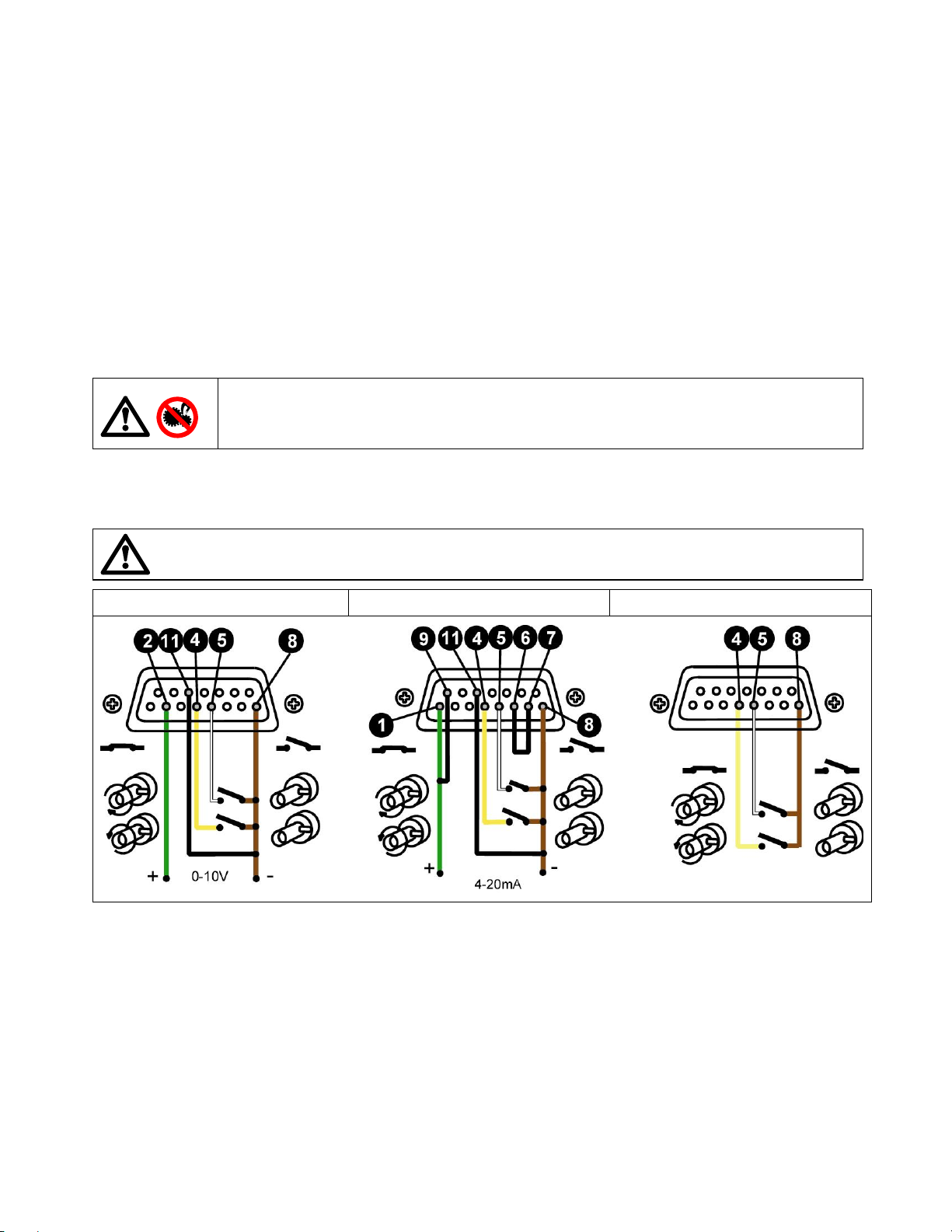
Remote control
The 403U and 405U dr ives can be controlled remotely via 0-10V or 4-20 mA anal ogue signals. 400AC1, 400AC2,
400AC3 and 400AC4 remote control cables with a 15-pin D-sub connector are available from your local WatsonMarlow dealer. Wiring diagrams for each control cable are shown at the bottom of this section.
When using the
switching cw/stop/ccw:
Set the pump to stop by pressing the
The keypad speed control setting sets the range of the remote speed signal, and it can be adjusted during remote
control use. (If the manual speed is set 50 %, only 50% of maximum speed will be achiev a ble at 10V or 20mA). It
is advisable to set the speed to 99.9 % f or fu ll an alogue speed range control.
Start or stop the pump in either cw or ccw direct ion remotely as shown in the relevant wiri ng diagrams. If the
remote switch is set to stop, cw or ccw direction switching can be a chie ved using the keypad.
When using the
Set the pump speed manually using the or keys.
Start or stop the pump in either cw or ccw direct ion remotely as shown in the relevant wiri ng diagram. If the
remote switch is set to stop, cw or ccw direction switching can be a chie ved using the keypad.
When using the
Set the pump to stop by pressing the
Pressing the footswitch will start the pump in the cw direction only. Releasing the footswitch will stop the pump.
400AC1 400AC2 400AC3
400AC1
400AC3
400AC4
In the event of a power failure when the pump is under remote control, the pump will automatically
re-start when the power is returned.
(0-10V) or
cw/stop/ccw remote cable
With a remote direction switch connected and the remote cw/stop/ccw switch set to cw or
ccw, you cannot switch direction manually. However, you can stop the pump manually
using the keypad which is designed to be used as an "emergency stop". The remote
cw/stop/ccw switch needs to be set to stop to release the "emergency stop".
start/stop 3m remote cable with footswitch fitted:
400AC2
(4-20mA) remote control cables for a na l og ue speed control and
key.
Stop
key
Stop
Care and maintenance
The only scheduled maintenance of the pump unit is to replace the motor brushes and to replace them when
necessary, understanding that motor brushes are not covered by the two year warranty. It is recommended that this
work be carried out by a Wats on-Marlo w ser vicing ag ent. Th e life of the b rus hes dep ends on the duty of the pu mp but
is expected to be at least 2500 hours at maximum speed for the 403U and 5000 hours for the 405U.
If the pump requires cleaning use a mild solution of detergent in water after removing the pumphead. Do not use
strong solvents.
4
Page 5

Pump spares
403U/VM 403U/R1 & 405U/R1
403U/L & 405U/L 403U/L2 & 405U/L2
Number Description
1
2
3
4
5
6
7
Tube clamping block 970075 990067 990029
Rotor 010020 010022 010017
Track 941024 941024 941024
Track occlusion arm 010040 010040 010040
Rotor screw MRX M5X10 A4 MRX M5X10 A4 MRX M5X10 A4
Rotor shaft pin CPR3H 8x 16 CPR3H 8x16 CPR3H 8x16
Case screws D6 B 35x10 NN A542
Part number
403U/VM2
SPTAND A4
Part number
D6 B 35x10 NN A542
SPTAND A4
Number Description
1
2
3
4
5
6
7
8
9
Tube clamps/block 010042 930325 010043
Rotor 010018 010019 010019
Track 970714 950058 950058
Track occlusion arm 010040 010040 010040
Rotor screw MRX M4X6 A4 MRX M5X6 A4 MRX M5X6 A4
Rotor shaft pin CPR3H 8x 16 CPR3H 8x16 CPR3H 8x16
Case screws D6 B 35x10 NN A542
Transparent guard 950163 950217 950217
Finger screw 950169 950169 950169
Part number
403U/R1, 405U/R1
SPTAND A4
Part number
403U/L, 405U/L
D6 B 35x10 NN A542
SPTAND A4
403U/VM3
Part number
403U/VM4
D6 B 35x10 NN A542
SPTAND A4
Part number
403U/L2, 405U/L2
D6 B 35x10 NN A542
SPTAND A4
5
Page 6

Specification
Maximum rotor speeds for 403U 10rpm, 50rpm
Maximum rotor speeds for 405U 200rpm
Voltage/frequency 040.****.**U 240V 50/60Hz
Voltage/frequency 040.****.**E 240V 50/60Hz
Voltage/frequency 040.****.**A 110V 50/60Hz
403U control range 20:1
405U control range 10:1
Operating temperature range 5 to 40C
Storage temperature range -40C to 70C
Noise <70 dBA @ 1m
Standards IEC 335-1, EN60529 (IP21)
Machinery Directive 2006/42/EC
EMC Directive 2004/108/EC
400R1, 400L & 400L2 and 400VM2, 400VM3 & 400VM4 pumpheads
Performance against pressure
The pressure and the suction height can be increased by compressing the spring in the track occlusion pin. A smaller
gap between the rollers and track will give better performance against pressure but will reduce tube life.
Other factors that will influence tube life in peristaltic pumps are pump speed (roller impacts/minute), chemical
compatibility of the duty fluid and viscosity of the duty fluid.
It is the pressure capability of the tubing that limits the operating pressure of the pump. The maximum pressure you
can obtain is dependent on the wall thic knes s, tu be bore and hardne ss of the tubing . Normally the ma ximum press ure
is 2 bar.
Key Safety Information
When fitting a new tube in the pumphead
Ensure that there is no pressure, liquid or gas in the pipeline.
Disconnect the pump from the mains to prevent the pump from starting unexpectedly.
Always replace any protective guard after tube changeover.
If a tube failure has occurred, ensure that any fluid in the pumphead has been allowed to drain to a safe area
Ensure that protective clothi n g and eye protection is worn if aggressive fluids are being pumped.
400R1 pumphead set-up
The 400R1 pumphead is designed to accept 1.6mm wall standard laboratory tubing up to 6.4mm bore. Care should
be taken to establish the normal tube life experienced within a set of operating parameters. Subsequent tubing
replacement should be scheduled wi thin the normal expected life of a tube. This will avoid unnecessary tube failure
and unplanned pump maintenance.
Tube loading (Pictures 1-9)
Remove the transparent guard.
Release the track by disengaging the track occlusion pin.
Before tube loading, mak e sur e that enough s uction and delivery tub ing is available to c onnect in to the remainin g
pipeline or to reach the suction reservoir and delivery point.
Locate the tubing into the suction side tube clamp. Feed the tubing in around the rotor, maintaining reasonable
tube tension so that the tube sits around the rotor, and locate into the delivery side tube clamp. Make sure that
there are no twists or kinks in the tubing after loading as this will adversely affect tube life.
Ensure the tube is lined up centrally in the track correctly secured at each clamp.
Re-position the track over the rotor and fix by slotting the track occlusion pin back into the track slot.
Re-attach the transparent guard.
Compressing the spring on the track occlusion pin (picture 10) will increase the suction height and performance
against back pressure.
6
Page 7

1 2 3 4
5 6 7 8
9 10 11 12
Occlusion setting
Increase the spring pressur e until the pump starts pumping and th en adjust the spring pr essure according to the
flow rate required, which will be governed by the suction condition.
pressure to the minimum required for satisfactory pumping.
Tube re-tensioning (pictures 10-12)
For longest tube life, set the spring
When using Marprene tubing
releasing the track occlusion pin and pulling the tubing on the discharge side a little. This is to counteract the
normal stretching that occurs with Marprene which can go unnoticed and result in poor tube life.
Tube removal
Release the track by disengaging the spru ng track occlusion pin and withdraw the tubi n g from the sprung clamps.
, after the first 30 minutes of running, re-tension the tube in the pumphead by
400L and 400L2 pumpheads set-up
The 400L is designed for 1.6mm wall elements up to 4.8mm bore, whereas the 400L2 accepts two 1.6mm wall
continuous lengths of tubing up to 4.8mm bore.
Care should be taken to establish th e normal tube life experien ced within a set of operatin g parameters. Subseq uent
tubing replacement should be scheduled within the normal expected life of a tube. This will avoid unnecessary tube
failure and unplanned pump maintenanc e.
Tube loading (Pictures 1-24)
Remove the transparent guard
Release the track by disengaging the track occlu sio n pin.
Before tube loading, mak e sur e that enough s uction and delivery tub ing is available to c onnect in to the remainin g
pipeline or to reach the suction reservoir and delivery point.
For 400L Y elements (pictures 1-9)
around the split rotor ensu ring that ea ch leg of th e elemen t sits centra lly over each sec tion of the roto r. Loc ate the
second y connection in the upper clamp block.
For 400L2 continuous tubing lengths (pictures 10-24)
Feed each tube in around the rotor, maintaining reasonable tube tension so that each tube sits centrally over each
locate one Y connection into the lower clamp block and feed the elements
locate the tubing into the suc tion side w-block clamp.
7
Page 8

section of the rotor. Locate into the delivery side w-block clamp. Make sure that there are no twists or kinks in the
tubing after loading as this will adversely affect tube life. If using a long length of tubing it is best to remove the wblock clamps to quickly locate a section of the tubing between the track and rotor.
Re-position the track over the rotor and fix by slotting the track occlusion pin back into the track slot.
Replace the transparent guard and secure in place.
Compressing the spring on the track occlusion pin (picture 9 and 22) will increase the suction height and
performance against back pressure.
1 2 3 4
5 6 7 8
9 10 11 12
13 14 15 16
17 18 19 20
21 22 23 24
8
Page 9

Tube re-tensioning (pictures 25-27)
When using Marprene tubing
releasing the track occlusion pin and upper w-block clamp and pulling the tubing on the delivery side a little. This
is to counteract the normal stretchin g that occurs with Marprene whic h can go unnoticed and result in poor tube
life.
, after the first 30 minutes of running, re-tension the tube in the pumphead by
25 26 27
Tube removal
Release the track by disengaging the tr ack occlu sion pin and withdraw the tubing from th e w-block clamps.
400VM2, 400VM3, 400VM4 pumpheads set up
The 410VM pumpheads are designed to acce pt two bridge manifold tubing only .
Tube loading (pictures 1-8)
Release the track by disengaging the track occlu sio n pin.
Locate the first tube bridge into the appropriate tube bridge holder slot. Feed the tubing around the rotor and
locate the centre tube br idge into the bridge ho lder slot immediately opp osite the first tube bridge. Repeat for th e
remaining one (400VM2) or two (400VM3) or three (400VM4) channels. Make sure that there are no twists or
kinks in the tubing after loading as this will adversely affect tube life.
Re-position each track over the rotor and fix by slotting the track occlusion pin back into the track slot.
Compressing the spring on the track occlusion pin (picture 8) will increase the suction height and performance
against back pressure.
1 2 3 4
5 6 7 8
Tube removal
Release the track by disengaging the track occlu sio n pin.
Remove both tubing bridges from thei r lo cation slots and remove the tubing from the pumphead.
9
Page 10

Flow rates
The tables below list the approximate water-flow rate per revolution for the 404D pumpheads. The flow rate will
depend on the duty fluid (viscosity, density etc.), pressure, temperature, speed, tubing and the installation. For
accurate flow rates and repeatability, calibrate the pump for your application.
400R1
Tube bore 0.5mm 0.8mm 1.6mm 2.4mm 3.2mm 4.0mm 4.8mm 6.4mm
Tube number 112 13 14 16 25 15
ml/rev
2.5 to 50rpm
20 to 200rpm
400L
Tube bore 0.5mm 0.8mm 1.6mm 2.4mm 3.2mm 4.0mm 4.8mm
Tube number 112 13 14 16 25
ml/rev
2.5 to 50rpm
20 to 200rpm
400L2
Tube bore 0.5mm 0.8mm 1.6mm 2.4mm 3.2mm 4.0mm 4.8mm
0.022 0.055 0.22 0.49 0.86 1.31 1.83 3.03
0.06-1.1 0.14-2.8 0.55-11 1.2-24 2.1-43 3.3-65 4.6-92 7.6-150
0.44-4.4 1.1-11 4.4-44 9.8-98 17-170 26-260 37-370 61-610
0.043 0.11 0.44 0.98 1.71 2.62 3.67
0.11-2.2 0.28-5.6 1.1-22 2.4-49 4.3-86 6.5-130 9.2-180
0.86-8.6 2.2-22 8.8-88 20-200 34-340 52-520 73-730
Tube number 112 13 14 16 25
ml/rev
2.5 to 50rpm
20 to 200rpm
0.022 0.055 0.22 0.49 0.86 1.31 1.83
0.06-1.1 0.14-2.8 0.55-11 1.2-24 2.1-43 3.3-65 4.6-92
0.44-4.4 1.1-11 4.4-44 9.8-98 17-170 26-260 37-370
400VM2, 400VM3, 400VM4
Colour Orange/black Orange/Red Orange/Blue Orange/Green Orange/yellow
Bore 0.13mm 0.005" 0.19mm 0.007" 0.25mm 0.010" 0.38mm 0.015" 0.50mm 0.020"
0.5-10rpm
2.5-50rpm
Colour Orange/White Black/Black Orange/Orange White/White Red/Red
Bore 0.63mm 0.025" 0.76mm 0.030" 0.88mm 0.035" 1.02mm 0.040" 1.14mm 0.045"
0.5-10rpm
2.5-50rpm
Colour Grey/Grey Yellow/Yellow Yellow/Blue Blue/Blue Green/Green
Bore 1.29mm 0.050" 1.42mm 0.055" 1.52mm 0.060" 1.65mm 0.065" 1.85mm 0.07
0.5-10rpm
2.5-50rpm
Colour Purple/Purple Purple/Black Purple/Orange Purple/White
Bore 2.05mm 0.080" 2.29mm 0.090" 2.54mm 0.100" 2.79mm 0.110"
0.5-10rpm
2.5-50rpm
0.001-0.01 0.001-0.03 0.002-0.004 0.005-0.1 0.01-0.2
0.003-0.06 0.006-0.13 0.011-0.2 0.025-0.5 0.04-0.9
0.01-0.3 0.02-0.4 0.03-0.5 0.03-0.7 0.04-0.9
0.07-1.4 0.10-2.0 0.13-2.6 0.17-3.5 0.21-4.3
0.05-1.1 0.06-1.3 0.07-1.4 0.08-1.7 0.10-2.0
0.27-5.4 0.32-6.4 0.36-7.2 0.41-8.3 0.50-10.0
0.12-2.3 0.14-2.7 0.16-3.1 0.17-3.4
0.59-12 0.69-14 0.78-16 0.85-17
10
Page 11

1.6mm wall continuous tubing
Tube product codes
mm " #
0.5 1/50 112 902.0005.016 903.0005.016 910.0005.016 913.0005.016
0.8 1/32 13 902.0008.016 903.0008.016 910.0008.016 913.0008.016
1.6 1/16 14 902.0016.016 903.0016.016 910.0016.016 913.0016.016
3.2 1/8 16 902.0032.016 903.0032.016 910.0032.016 913.0032.016
4.8 3/16 25 902.0048.016 903.0048.016 910.0048.016 913.0048.016
6.4 1/4 17 902.0064.016 903.0064.016 910.0064.016 913.0064.016
8.0 5/16 18 902.0080.016 903.0080.016 910.0080.016 913.0080.016
mm " # Butyl * Tygon Fluorel Neoprene
0.8 1/32 13
1.6 1/16 14 930.0016.016 950.0016.016 970.0016.016 920.0016.016
3.2 1/8 16 930.0032.016 950.0032.016 970.0032.016 920.0032.016
4.8 3/16 25 930.0048.016 950.0048.016 970.0048.016 920.0048.016
6.4 1/4 17 930.0064.016 950.0064.016 970.0064.016 920.0064.016
8.0 5/16 18 930.0080.016 950.0080.016 970.0080.016 920.0080.016
Marprene Bioprene Peroxide Silicone Platinum Silicone
920.0008.016
Manifold tubing product codes
Bore
mm Bore "
0.13 0.005 984.0013.000
0.19 0.007 984.0019.000
0.25 0.010 978.0025.000 980.0025.000 984.0025.000
0.38 0.015 978.0038.000 980.0038.000 984.0038.000
0.50 0.020 978.0050.000 980.0050.000 984.0050.000 986.0050.000
0.63 0.025 978.0063.000 980.0063.000 982.0063.000 984.0063.000 986.0063.000
0.76 0.030 978.0076.000 980.0076.000 982.0076.000 984.0076.000 986.0076.000
0.88 0.035 978.0088.000 980.0088.000 982.0088.000 984.0088.000 986.0088.000
1.02 0.040 978.0102.000 980.0102.000 982.0102.000 984.0102.000 986.0102.000
1.14 0.045 978.0114.000 980.0114.000 982.0114.000 984.0114.000 986.0114.000
1.29 0.050 978.0129.000 980.0129.000 982.0129.000 984.0129.000 986.0129.000
1.42 0.055 978.0142.000 980.0142.000 982.0142.000 984.0142.000 986.0142.000
1.47 0.058 982.0147.000
1.52 0.060 978.0152.000 980.0152.000 982.0152.000 984.0152.000 986.0152.000
1.65 0.065 978.0165.000 980.0165.000 982.0165.000 984.0165.000 986.0165.000
1.85 0.070 978.0185.000 980.0185.000 982.0185.000 984.0185.000 986.0185.000
2.05 0.080 978.0205.000 980.0205.000 982.0205.000 984.0205.000 986.0205.000
2.29 0.095 978.0229.000 980.0229.000 982.0229.000 984.0229.000 986.0229.000
2.54 0.100 978.0254.000 980.0254.000 982.0254.000 984.0254.000 986.0254.000
2.79 0.110 978.0279.000 980.0279.000 982.0279.000 984.0279.000 986.0279.000
Marprene
PVC
Silicone
Solvent
resistant
Acid
resistant
11
Page 12

Outline dimensions
r
403U/VM2 403U/VM3 403U/VM4
403U/R1 403U/L 403U/L2
405U/R1 405U/L 405U/L2
Watson-Marlow, Bioprene
Warning, these products are not designed for use in, and should not be used for patient connected
applications.
The information contained in this document is believed to be correct but Watson-Marlow Limited accepts no liability fo
any errors it contains, and reserves the right to alter s pecifications without notice.
and
Marprene
are trademarks of
Watson-Marlow Limited.
12
Page 13

Product use and decontamination declaration
.
.
.
.
In compliance with the
Regulations
you are returning to Watson-M arlow or any of its subsidiaries or dis tributors. Failure to do so will cause delays in
servicing the product. Therefor e, pleas e comp le te th is for m to en s ure th at we ha ve the inform ation be for e receip t of
the product(s) being returned. A FURTHER COPY
PACKAGING CONTAINING THE PRODUCT(S). You, the user, are responsible for cleaning and decontaminating
the product(s) before returning them.
Please complete a separate Decontamination Certificate for each pump returned.
1 Company
Address ……… ........................................................................Postcode ………………………………………
Telephone ……………………………………………. ................ Fax Number …………………………………..
2.1 Serial Number … … … … … … … … … … … … … ..........(a)………………………………………………….
2.2 Has the Product been used? (b)…………………………………………………
YES NO (c)…………………………………………………
(d)…………………………………………………
If yes, please complete all the following Sections. If no, please complete Section 5 only
3 Details of substances
pumped
3.1 Chemical names:
(a)……………… ..........................
(b)……………..............................
(c)……………… ..........................
(d)……………..............................
3.2 Precautions to be taken in handling these substances: To assist servicing, please describe any fault
(a)………… ......................................................... condition(s) you have witnessed
(b)………… ........................................................…………………………………………………
(c) ……………… ..................................................……………………………………………………………
(d)………………. ..................................................……………………………………………………………
3.3 Action to be taken in the event of human contact:
..........……………………………………………………………………………………………………
(a)………………………………………………………………….……………………………………………………………
(b)………………………………………………………………….……………………………………………………………
(c)………….……………………………………………………………………………………………………………………
(d)………….……………………………………………………………………………………………………………………
3.4 Cleaning fluid to be used if residue of chemical is found: ……………………………………………………………
(a)…………………………………………………………………. ……………………………………………………………
(b)…………………………………………………………………. ……………………………………………………………
(c)………….……………………………………………………………………………………………………………………
(d)………….……………………………………………………… ……………………………………………………………
Watson-Marlow Bredel Pumps . Falmout h . Cornwall TR11 4RU . England . Tel: 01326 370370 . Fax: 01326 376009
you, the user are required to declar e the substances which have b een in contact with the product(s)
UK Health & Safety at Work Act
4 I hereby confirm that the only substa nces(s) that the equipmen t specified has
pumped or come into contact with are th ose n amed, that the information give n is
correct, and the carrier has been informed if the consignment is of a hazardous
nature.
5 Signed …………………………………………………………………………………
Name …………………………………………………………………………………
Position ……………………………………………………………………………….
Date …………………………………………………………………………………..
and the
MUST
Control of Substances Hazardous to Health
BE ATTACHED TO THE OUTSIDE OF THE
RGA No:
…………………...
13
 Loading...