

Page 1

313F, 313S, 313U, 313T
313fstu-gb-03.pdf
Page 2
Declarations
Declaration of
conformity
When this pump unit is used as a stand alone pump it complies with: Machinery Directive
98/37/EC EN60204-1, Low Voltage Directive 73/23/EEC EN61010-1, EMC Directive
89/336/EEC, EN50081-1/EN50082-1.
Declaration of
Incorporation
Responsible person: Dr R Woods, Managing Director, Watson-Marlow Limited, Falmouth, Cornwall TR11 4RU, England.
Telephone 01326 370370 Fax 01326 376009.
Two year warranty
Watson-Marlow Limited warrants, subject to the conditions below, through either Watson-Marlow Limited, its
subsidiaries, or its authorised distributors, to repair or replace free of charge, including labour, any part of this product
which fails within two years of delivery of the product to the end user. Such failure must have occurred because of defect
in material or workmanship and not as a result of operation of the product other than in accordance with the instructions
given in this manual.
Conditions of and specific exceptions to the above warranty are:
When this pump unit is to be installed into a machine or is to be assembled with other
machines for installations, it must not be put into service until the relevant machinery has
been declared in conformity with the Machinery Directive 98/37/EC EN60204-1.
• Consumable items such as tubing, rollers and brushes are excluded.
• Products must be returned by pre-arrangement carriage paid to Watson-Marlow Limited, its subsidiaries, or its
authorised distributor.
• All repairs or modifications must have been made by Watson-Marlow Limited, its subsidiaries, or its authorised
distributors or with the express permission of Watson-Marlow Limited, its subsidiaries, or its authorised distributors.
• Products which have been abused, misused, or subjected to malicious or accidental damage or electrical surge are
excluded.
Warranties purporting to be on behalf of Watson-Marlow Limited made by any person, including representatives of
Watson-Marlow Limited, its subsidiaries, or its distributors, which do not accord with the terms of this warranty shall not
be binding upon Watson-Marlow Limited unless expressly approved in writing by a Director or Manager of Watson-Marlow
Limited.
Information for returning pumps
Equipment which has been contaminated with, or exposed to, body fluids, toxic chemicals or any other substance
hazardous to health must be decontaminated before it is returned to Watson-Marlow or its distributor.
A certificate included at the rear of these operating instructions, or signed statement, must be attached to the outside of
the shipping carton.
This certificate is required even if the pump is unused. If the pump has been used, the fluids that have been in contact
with the pump and the cleaning procedure must be specified along with a statement that the equipment has been
decontaminated.
Safety
In the interests of safety, this pump and the tubing selected should only be used by competent, suitably trained
personnel after they have read and understood this manual, and considered any hazard involved.
Any person who is involved in the installation or maintenance of this equipment should be fully competent to carry out the
work. In the UK this person should also be familiar with the Health and Safety at Work Act 1974.
There are dangerous voltages (at mains potential) inside the pump. If access is required,
isolate the pump from the mains before removing the cover.
Page 3

Recommended operating procedures
DO keep delivery and suction lines as short as possible using a minimum number of swept bends.
DO use suction and delivery pipelines with a bore equal to or larger than the bore of the tube fitted in the pumphead.
When pumping viscous fluids, the losses caused by increased friction can be overcome by using pipe runs with a cross
sectional area several times greater than the pumping element.
DO fit an extra length of pump tube in the system to enable tube transfer. This will extend tube life and minimise the
downtime of the pumping circuit.
DO keep the track and rollers clean.
The self-priming nature of peristaltic pumps means valves are not required Any valves fitted must cause no restriction to
flow in the pumping circuit.
When using Marprene tubing, after the first 30 minutes of running, re-tension the tube in the pumphead by releasing
the tube clamp on the delivery side a little and pulling the tube tight. This is to counteract the normal stretching that
occurs with Marprene which can go unnoticed and result in poor tube life.
Tube selection The chemical compatibility list published in the Watson-Marlow catalogue is only a guide. If in doubt
about the compatibility of a tube material and the duty fluid, request a tube sample card for immersion trials.
Installation
The 313F, 313S and 313U are suitable for single phase mains electricity supplies only.
To ensure correct lubrication of the gearbox the pump should be run only while its feet are standing on a horizontal
surface. The pump should be positioned to allow a free flow of air around it.
Set the voltage selector to either 120V for 100-120V 50/60Hz supplies or 240V for 220-240V 50/60Hz supplies.
A mains cable fitted with a moulded plug is supplied with the pump. The wires are colour coded in accordance with the
following code:
• 220-240V: Live - Brown; Neutral - Blue; Earth - Green/Yellow.
• 100-120V: Live - Black; Neutral - White; Earth - Green.
Troubleshooting
Should the pump fail to operate, make the following checks to determine whether or not servicing is required.
• Check that the power switch is on.
• Check the mains supply is available at the pump.
• Check the voltage selector switch is in the correct position. l
• Check the fuse in the mains socket.
• Check that the pump is not stalled by incorrect fitting of tubing.
313F/D manual operation
• Set the voltage selector to either 120V for 100-120V 50/60Hz single phase AC supplies or 240V for 220-240V 50/60Hz
single phase AC supplies.
• Set the pump to the desired high or low speed setting using the horizontal slider switch on the rear panel.
• Stop Stop the pump by turning the Forward/Off/Reverse switch to its central Off position.
313S/D, 313U/D manual operation
• Set the voltage selector to either 120V for 100-120V 50/60Hz single phase AC supplies or 240V for 220-240V 50/60Hz
single phase AC supplies.
• Set the pump to the desired speed output using the front panel potentiometer.
• Turn the pump on using the mains power switch on the rear panel.
• Start up direction Start the pump by turning the Forward/Off/Reverse switch to the required direction of rotation.
• Stop Stop the pump by turning the Forward/Off/Reverse switch to its central Off position.
Note: When the pump is running clockwise in manual operation and is switched to standby, it will come to a dead stop.
When running counter clockwise it will freewheel to a stop. Any application requiring braking should have the pump set
up for clockwise running.
3
Page 4
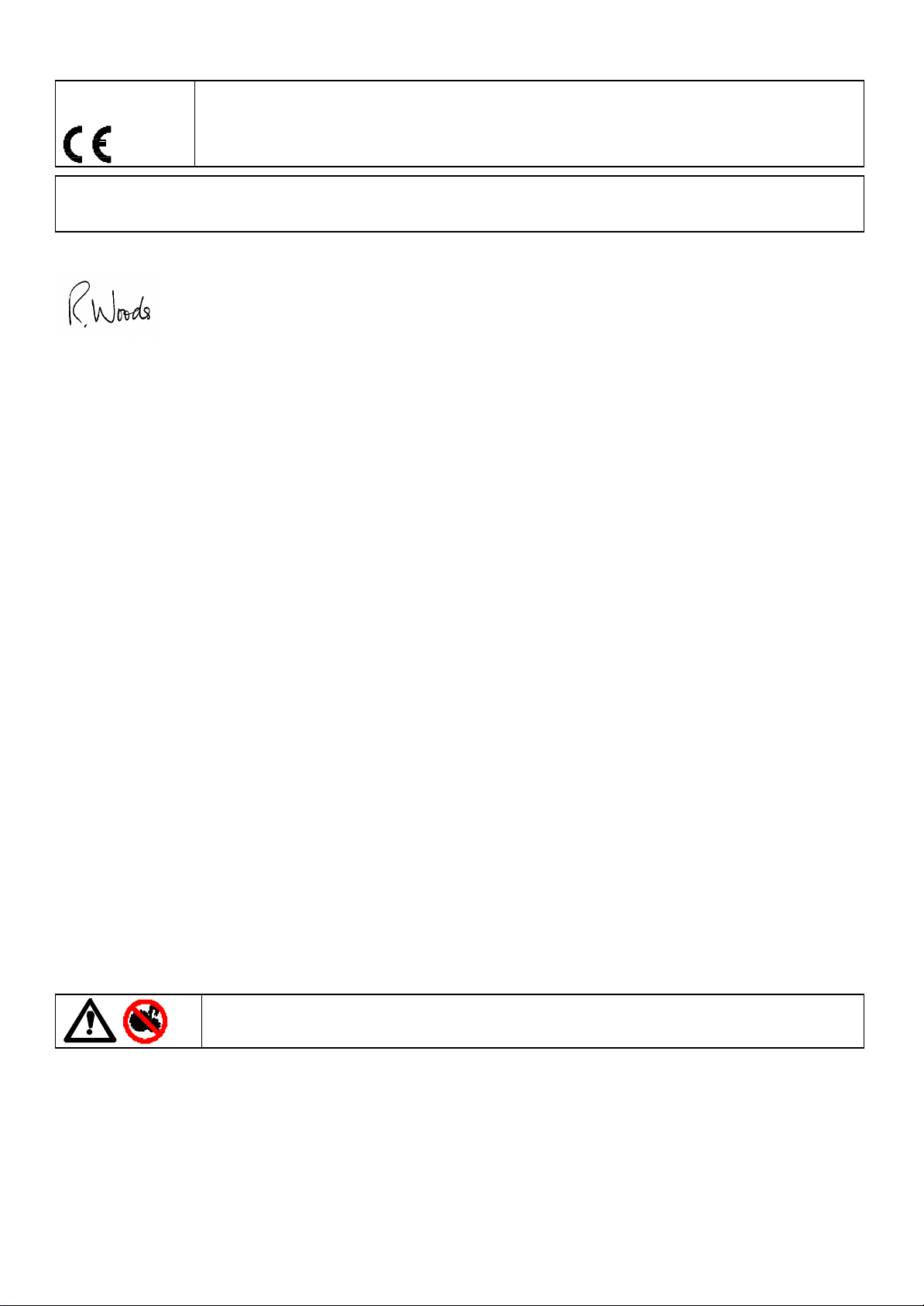
313U automatic operation
For the pump to be controlled by a process signal, the auto volts/manual/auto current (V M I) slider switch on the rear
panel should be set to either auto volts or auto current depending upon the type of control signal to be used. Ensure that
the mains switch on the rear panel is off. The process signal must be connected to the 25-way Dee plug provided, which
must be inserted in the rear panel 25-way Dee connector. The pump is controllable by an analogue process signal of up
to 0 to 10V or 4 to 20mA. The pump will provide an increasing flow rate for rising control signal (non-inverted response ).
Voltage signal
Input impedance 220 kohms. Maximum
voltage signal 10V
Current signal
Input impedance 250 ohms
Never apply mains voltage across any pins on the 25D socket. Up to 10V may be applied across pins
4 and 17, but no voltage should be applied across other pins. Permanent damage, not covered by
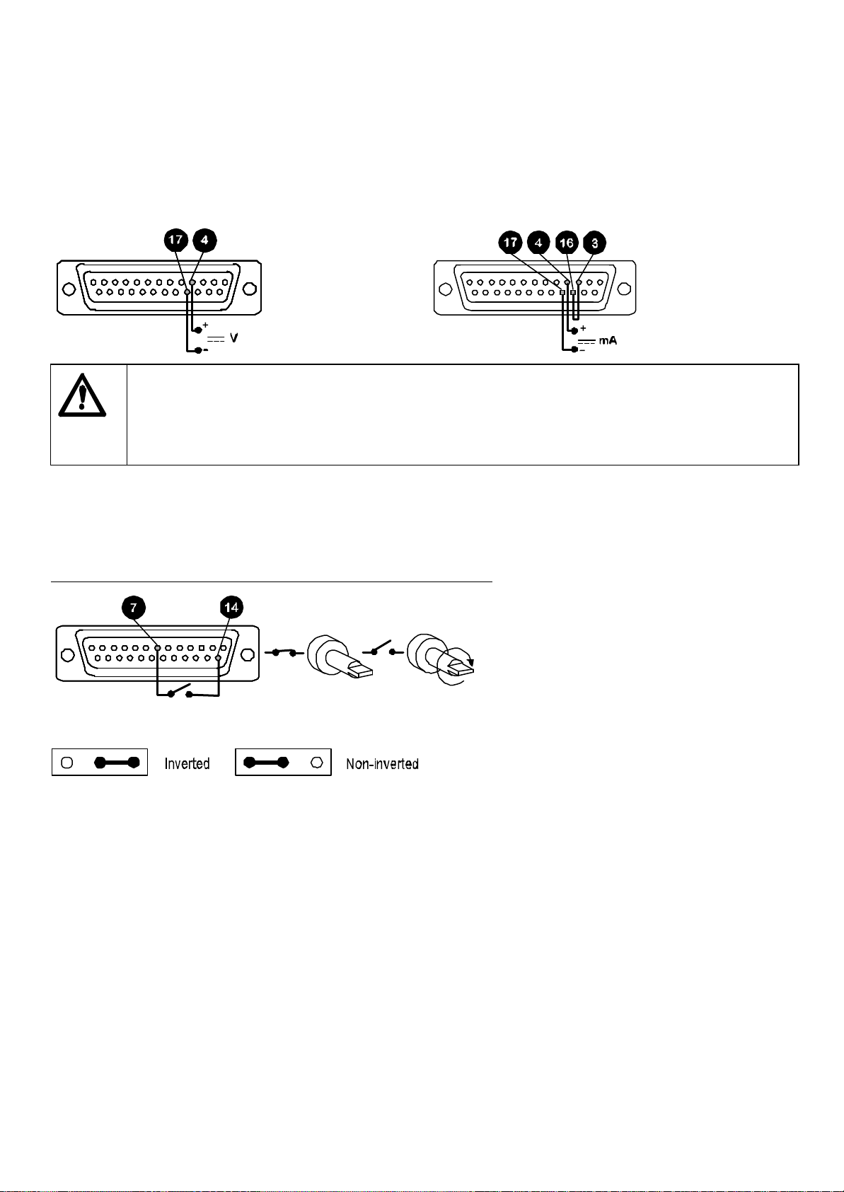
Remote control
Stop/Start
Connect remote switch between pins 7 and 14 of the 25 pin socket. Close contact to stop the pump, open to run. With
no connection, the pump will default to running. A remote stop/start signal will control the pump whilst running under
manual operation.
A TTL compatible logic input (Low 0V High 5V ) may be applied to pin 7.
To invert the response to the signal input move the remote stop signal inverter link (see 313 "U" upgrade card, item 4,
LK2) to the inverted pin positions on the signal inverter link block.
warranty may result in both instances. Do not use the mains power switch to control the pump for a
high repetition of stop/starts. The auto-control facility should be used.
When setting the drive control mode with the V M I switch ensure that power to the drive is switched
off using the mains switch on the rear panel.
Note: When the pump is running in either direction and is stopped remotely, it will freewheel to a stop.
4
Page 5
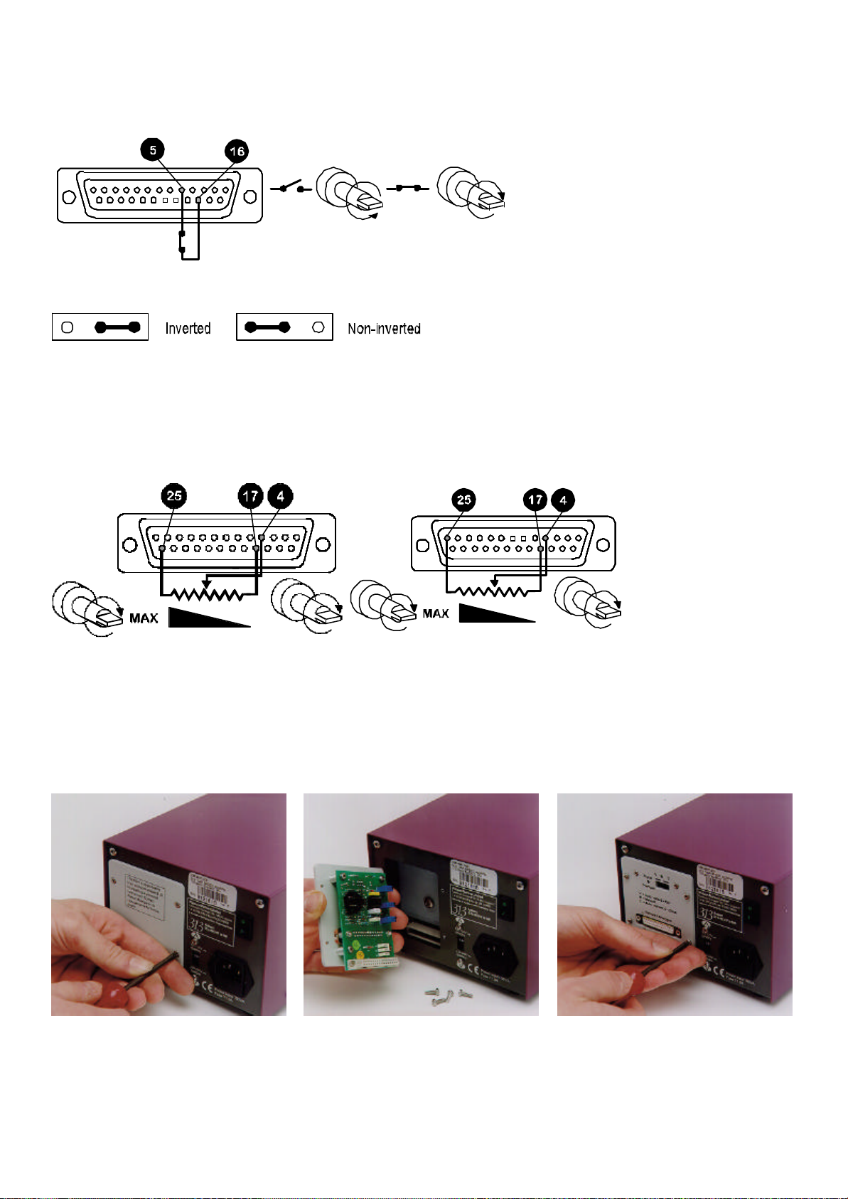
Direction
The remote direction facility operates with the front panel direction switch set in the anti-clockwise direction
only. Connect remote switch between pins 5 and 16. Open switch for anti-clockwise rotation, close for clockwise
rotation. With no connection, the pump will default to anti-clockwise
To invert the response to the signal input move the remote direction signal inverter link LK1 (see 313 "U" upgrade card,
item 6, LK1) to the inverted pin positions on the signal inverter link block.
Note: When the front panel switch is set to CCW rotation, the drive rotates according to the remote switch direction set
by LK1. When the front panel switch is set to CW rotation the remote switch is inhibited.
Speed
A remote potentiometer with a nominal value of between 1K and 2K with a minimum of 0.25W should be wired as shown.
When using a remote potentiometer, do not apply a voltage/current control input signal at the same time. Set the drive
control mode to auto volts (0-10V). Ensure that when changing the drive control mode, power to the drive is switched off
using the rear panel mains switch.
Note: As the remote potentiometer utilises the 0-10V range the speed response is only over 10/
ths
of the potentiometer's
12
electrical travel. The signal overload illuminates at this point and there is no further increase in speed.
313U upgrade card
To upgrade the manually controllable 313S/D into a remote or 0-10V/4-20mA analogue controllable 313U/D a 313U
upgrade card will be required (part number 039.3001.U00). To install the "U" card, undo the four M3 screws on the drive
rear panel "S" version cover plate and remove. Slot the 313U upgrade card into the rear panel recess, drop down to align
the DIN edge connectors and push into position. Replace the four M3 screws on the card to secure it firmly to the rear
panel.
5
Page 6

313U upgrade card spares
Item Part number Description
1 SD 0087 Signal overload LED indicator
2 DE 1645S Cover plate
3 US 0072 25-way Dee connector socket
4 US 0047 Remote stop signal inverter link
5 SW 0160 Auto voltage / manual / auto current switch 50V 2A
6 US 0047 Remote direction signal inverter link
7 PC 0147P Analogue PCB
8 SL 0091 DIN edge connector
6
Page 7

313T
The function of the 313T timer card is to convert 313S/D manually controlled drives into 313T/D drives allowing simple
dosing operations to be performed.
The single/continuous/ repeat slider switch allows the user to select between single shot dosing, continuous manual
pumping, or repeat dosing operations.
This publication should be used in conjunction with the manual provided with the pump.
Installation
Dosing
For the pump to be controlled as a simple dosing pump, the Single/Continuous/Repeat slider switch should be set to
Single or Repeat. When set on continuous, the timing functions are over-ruled and the pump operates as a manual
control variable speed unit, (front panel control).
The pump has a braking feature in the counter clockwise direction when viewed from the front of the pump, but not in the
clockwise direction. The dosing operation will therefore be more accurate when run counter clockwise.
The dosing times are set by means of two manually adjusted potentiometers on the "T" card. The right hand knob
adjusts the run time from zero to 10 seconds and the left hand one adjusts the off time from zero to 10 seconds.
Single dose set-up
• Set the slider switch to Single.
• Set the "on time" (dosing) knob on the rear of the pump as required and set pump speed to provide the required dose.
• Ensure the pump is set to run in the counter clockwise direction.
• The pump can be operated either from the Start button on the rear of the pump, or by closing a contact briefly across
pins 8 and 9 on the 25 pin socket.
Repeat dose set-up
• Set the slider switch to Repeat.
• Set the "on time" (dosing) knob and the "off time" knob on the rear of the pump as required and set pump speed to
provide the required dose.
• Ensure the pump is set to run in the counter clockwise direction.
• The pump can be operated either from the Start button on the rear of the pump, or by closing a contact briefly across
pins 8 and 9 on the 25 pin socket.
To stop the dosing operation either:
• Turn the CW/Standby/CCW to standby
• Pressthe Start button for longer than the off time,
• Close the contacts on pins 8 and 9 for longer than the off time.
For monitoring purposes, there is an unbuffered strobe output on pin 10 where 0V is stop and +5V is run in the timing
modes. For use with external instrumentation it must be buffered.
7
Page 8

313T major components
1 PCB cover
2 "Off time" knob
3 Pushbutton switch
4 Slider switch
5 "On time" knob
6 25 Din socket
Care and maintenance
The only scheduled maintenance of the 313F, 313S and 313U is to inspect the motor brushes and to replace them before
their length is less than 6mm 1/4". The life of the brushes will depend on the duty of the pump, which is expected to be
at least 7,500 hours at maximum speed. When the pump needs cleaning, remove the pumphead and use a mild solution
of detergent in water. Do not use strong solvents.
If the gearbox is dismantled, it should be filled with a good quality grease such as Castrol MS3.
Specification
313F/D nominal rotor speeds 5/50rpm, 200/400rpm
313U/D, 313S/D maximum rotor speeds 50rpm and 400rpm
Operating voltages and frequencies 110-240V 50/60Hz
313 S/D, 313U/D speed control ratio 20:1
Power rating 100VA
Operating temperature 5C to 40C
Storage temperature range -40C to 70C
Weight 5.35kg, 12Ib
Noise <70dBA at 1m
Standards IEC 335-1, EN60529 (IP31)
Machinery Directive:98/37/EC EN60204-1
Low Voltage Directive:73/23/EEC EN61010-1
EMC Directive:89/336/EEC EN50081-1/ EN50082-1
8
Page 9
313 and 314 pumpheads
The 313F/D, 313S/D and 313U/D can only be fitted with 313 three roller or 314 four roller pumpheads.
The 313 pumphead has three rollers and is designed to provide high flow rates, whilst with four rollers, the 314 pumphead
provides the option of less pulsation and greater pumping precision.
Both pumpheads employ a "clamp and stretch" tube clamping motion which ensures that the tube is held correctly in
position with no unwanted tube slackness.
The flip top track provides easy front end tube loading with no removal of components.
The simple bayonet mounting action for standard and extension pumphead fitting allows easy fast set up of ganged
installations.
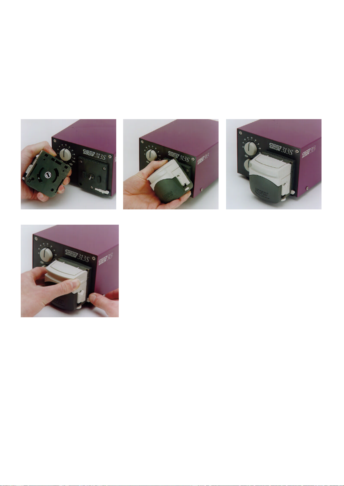
Installation
All 313 drives are provided with bayonet plate fittings attached. To fit a 313 or 314 pumphead, align the slot in the
pumphead to the drive tang and using the bayonet fittings, turn the pumphead clockwise and snap into position.
To remove the pumphead push the bayonet plate locking lever back towards the rear of the drive and turn the pumphead
anti-clockwise until it is freed from the bayonet plate fittings.
Flow rates
Flow rates for the 313F, 313S and 313U were obtained using silicone tubing, with the pumphead rotating clockwise at
100rpm, pumping water at 20C with zero suction and delivery pressures (unless otherwise stated). For critical
applications determine flow rates under operating conditions.
9
Page 10

Tube loading
• Switch off the pump before tube loading.
• Lift the "flip top" track until fully open.
• Set the pumphead tube clamps, with the track open to the required tube size, using the calibrations on each side of
the pumphead.
• In some applications (where the outside of the tube is dirty or there is a high suction lift), the tube clamps may need
to be adjusted to a smaller setting to give effective tube clamping
• Select the length and bore size of tube required, ensuring the tube is long enough to cover the source to delivery
distance and the curvature of the track.
• Fit the tubing across the pumphead rotor and lower the track. Ensure the tubing is fitted correctly between the rollers
and track, and that there is no pinching of the tubing by the tube clamps. The tubing must lie naturally against the
track and must not be twisted or over stretched.
10
Page 11

Fitting an extension pumphead
• Remove the first 313 or 314 pumphead by pushing the bayonet plate locking lever back towards the rear of the drive
and turn the pumphead anti-clockwise until it is freed from the bayonet plate fittings. The extension pumphead can
now be fitted.
• Align the slot in the extension pumphead to the drive tang and using the bayonet fittings turn the pumphead clockwise
and snap into position.
• Align the drive slot of the next pumphead to the drive tang of the extension pumphead, turn the next pumphead
clockwise and snap into position.
If aggressive liquids are spilled onto the pumphead, it should be removed and cleaned using a mild solution of detergent
and water. Remove any tubing from the pumphead, and wash thoroughly.
Check moving parts of the rotor from time to time for freedom of movement. Lubricate pivot points and rollers occasionally
with Teflon lubricating oil.
11
Page 12

Drive spares
Item Part number Description
1 DE 1654B Rotary switch
2 DE 1663B Potentiometer
3 DE 1647M Soft touch knob
4 DEA1609A Bayonet plate
5 FB 0009 Foot
6 DEA1616A Motor gearbox 50rpm
DEA1611A Motor gearbox 400rpm
7 DEA1636A 313S Control PCB: calibrated at 400 rpm
DEA1635A 313S Control PCB: calibrated at 50 rpm
DEA1638A 313F Control PCB: calibrated at 400 rpm
DEA1637A 313F Control PCB: calibrated at 50 rpm
8 DE 1666M 313S PCB cover
9 SW 0123 Speed selector switch (slider) 313F
10 SW 0167 Switch (slider) 250VAC
11 FS 0003 Fuse 1.0 amp T type
12 SW 0147 Switch (rocker) 250VAC
13 DE 1661H Earth lead
14 DE 1649H LT/AC harness
15 TF 0047 Transformer
16 DE 1650H/ DE 1632H Control harness 313S/D, 313U/D/ 313F/D
BM 0019 Motor brush
12
Page 13

313 (ml/min) flow rates
Tube number
Tube bore
Tube bore
Rpm
Rpm
Rpm
Rpm
Rpm
Rpm
314 (ml/min) flow rates
Number
Bore
Bore
Rpm
Rpm
Rpm
Rpm
Rpm
Rpm
313 and 314 maximum number of pumpheads
313 and 314 Peroxide/ Platinum Silicone
Number
Bore
Bore
Rpm
Rpm
Rpm
Rpm
313 and 314 Marprene, Tygon, Neoprene, Viton.
Number
Bore
Bore
Rpm
Rpm
Rpm
Rpm
# 112 13 14 16 25 17 18 112 13 14 16 25 17 18
mm 0.5 0.8 1.6 3.2 4.8 6.4 8.0 0.5 0.8 1.6 3.2 4.8 6.4 8.0
" 1/50 1/32 1/16 1/8 3/16 1/4 5/16 1/50 1/32 1/16 1/8 3/16 1/4 5/16
5
50
200
400
# 112 13 14 16 25 17 18 112 13 14 16 25 17 18
mm 0.5 0.8 1.6 3.2 4.8 6.4 8.0 0.5 0.8 1.6 3.2 4.8 6.4 8.0
" 1/50 1/32 1/16 1/8 3/16 1/4 5/16 1/50 1/32 1/16 1/8 3/16 1/4 5/16
5
50
200
400
# 112 13 14 16 25 17 18
mm 0.5 0.8 1.6 3.2 4.8 6.4 8.0
" 1/50 1/32 1/16 1/8 3/16 1/4 5/16
5 0.15 0.33 1.3 5 11 18 25
50 1.5 3 13 50 110 180 250
200 6 14 54 200 440 720 1000
400 12 28 108 400 880 1440 2000
2.5 - 50 0.07-1.5 0.15-3 0.65-13 2.5-50 5.5-110 9-180 12.5-250
20 - 400 0.6-12 1.4-28 5.4-108 20-400 44-880 72-1440 100-2000
# 112 13 14 16 25 17 18
mm 0.5 0.8 1.6 3.2 4.8 6.4 8.0
" 1/50 1/32 1/16 1/8 3/16 1/4 5/16
5 0.15 0.3 1.2 4.2 9.5 15 20
50 1.5 3.0 12 42 95 150 200
200 6 12 50 170 330 600 800
400 12 24 100 340 760 1200 1600
2.5-50 0.07-1.5 0.15-3.0 0.6-12 2.1-42 4.8-95 7.5-150 10-200
20-400 0.6-12 1.2-24 5-100 17-340 38-760 60-1200 80-1600
(0 = bar = 2) (0.5 = bar = 2.0)
6 6 6 6 6 4 3 6 6 6 6 5 3 3
6 6 6 6 6 4 3 6 6 6 6 5 3 3
6 6 5 3 2 2 1 6 6 5 3 2 1 1
6 6 5 3 2 2 1 6 6 5 3 2 1 1
(0 = bar = 0.5) (0.5 = bar = 2.0)
6 6 6 6 5 3 3 6 6 6 6 4 3 3
6 6 6 6 5 3 3 6 6 6 6 4 3 3
6 6 4 2 2 1 1 6 6 4 2 2 1 1
6 6 4 2 2 1 1 6 6 4 2 2 1 1
13
Page 14

Tubing for 313D, 314D, 313X and 314X pumpheads
Product codes
Bore Bore
Mm " # Marprene Bioprene Peroxide Silicone Platinum Silicone
0.5 1/50 112 902.0005.016 903.0005.016 910.0005.016 913.0005.016
0.8 1/32 13 902.0008.016 903.0008.016 910.0008.016 913.0008.016
1.6 1/16 14 902.0016.016 903.0016.016 910.0016.016 913.0016.016
3.2 1/8 16 902.0032.016 903.0032.016 910.0032.016 913.0032.016
4.8 3/16 25 902.0048.016 903.0048.016 910.0048.016 913.0048.016
6.4 ¼ 17 902.0064.016 903.0064.016 910.0064.016 913.0064.016
8.0 5/16 18 902.0080.016 903.0080.016 910.0080.016 913.0080.016
Bore Bore
mm " # Tygon Fluorel Neoprene STA-PURE
0.8 1/32 13 920.0008.016
1.6 1/16 14 950.0016.016 970.0016.016 920.0016.016 960.0016.016
3.2 1/8 16 950.0032.016 970.0032.016 920.0032.016 960.0032.016
4.8 3/16 25 950.0048.016 970.0048.016 920.0048.016 960.0048.016
6.4 1/4 17 950.0064.016 970.0064.016 920.0064.016 960.0064.016
8.0 5/16 18 950.0080.016 970.0080.016 920.0080.016 960.0080.016
Tubing for 313D2, 314D2, 3132X and 3142X pumpheads
Product codes
Bore Bore
mm " # STA-PURE Marprene Peroxide Silicone Platinum Silicone
0.5 1/50 105 902.0005.024 910.0005.024 913.0005.024
0.8 1/32 108 902.0008.024 910.0008.024 913.0008.024
1.6 1/16 119 960.0016.024 902.0016.024 910.0016.024 913.0016.024
3.2 1/8 120 960.0032.024 902.0032.024 910.0032.024 913.0032.024
4.8 3/16 15 960.0048.024 902.0048.024 910.0048.024 913.0048.024
6.4 1/4 24 960.0064.024 902.0064.024 910.0064.024 913.0064.024
8.0 5/16 121 960.0080.024
Flow rates against suction and pressure
14
Page 15

313F outline dimensions
313S and 313U outline dimensions
Watson-Marlow, Bioprene and Marprene are trademarks of Watson-Marlow Limited.
Tygon is a trademark of the Norton Company.
Warning, These products are not designed for use in, and should not be used for patient connected
applications.
The information contained in this document is believed to be correct but Watson-Marlow Limited accepts no liability for
any errors it contains, and reserves the right to alter specifications without notice.
15
Page 16

Product use and decontamination declaration
In compliance with the UK Health & Safety at Work Act and the Control of Substances Hazardous to Health
Regulations you, the user are required to declare the substances which have been in contact with the product(s) you
are returning to Watson-Marlow or any of its subsidiaries or distributors. Failure to do so will cause delays in servicing
the product. Therefore, please complete this form to ensure that we have the information before receipt of the
product(s) being returned. A FURTHER COPY MUST BE ATTACHED TO THE OUTSIDE OF THE PACKAGING
CONTAINING THE PRODUCT(S). You, the user, are responsible for cleaning and decontaminating the product(s)
before returning them.
Please complete a separate Decontamination Certificate for each pump returned. RGA No: …………………...
1 Company
Address ………...................................................................Postcode ………………………………………
Telephone ……………………………………………. .................Fax Number …………………………………..
2.1 Serial Number … … … … … … … … … … … … … ........... (a)………………………………………………….
2.2 Has the Product been used? (b)…………………………………………………
YES NO (c)…………………………………………………
(d)…………………………………………………
If yes, please complete all the following Sections. If no, please complete Section 5 only
3 Details of substances pumped
3.1 Chemical names:
(a)………………..........................
(b)…………….............................
(c)………………..........................
(d)…………….............................
3.2 Precautions to be taken in handling these substances: To assist servicing, please describe any fault
(a)………… .................................................... condition(s) you have witnessed
(b)………… ................................................... …………………………………………………
(c) ………………............................................... ……………………………………………………………
(d)………………................................................ ……………………………………………………………
3.3 Action to be taken in the event of human contact: ……………………………………………………………………………………………………
(a)…………………………………………………………………. ……………………………………………………………
(b)…………………………………………………………………. ……………………………………………………………
(c)………….……………………………………………………… ……………………………………………………………
(d)………….……………………………………………………… ……………………………………………………………
3.4 Cleaning fluid to be used if residue of chemical is found: ……………………………………………………………
(a)…………………………………………………………………. ……………………………………………………………
(b)…………………………………………………………………. ……………………………………………………………
(c)………….……………………………………………………… ……………………………………………………………
(d)………….……………………………………………………… ……………………………………………………………
4 I hereby confirm that the only substances(s) that the equipment specified has
pumped or come into contact with are those named, that the information given is
correct, and the carrier has been informed if the consignment is of a hazardous
nature.
5 Signed …………………………………………………………………………………
Name …………………………………………………………………………………
Position ……………………………………………………………………………….
Date …………………………………………………………………………………..
Watson-Marlow Bredel Pumps . Falmouth . Cornwall TR11 4RU . England . Tel: 01326 370370 . Fax: 01326 376009
16
 Loading...