

Page 1

205S, 205U
205suca-gb-02.pdf
Page 2
Declarations
Declaration of
conformity
When this pump unit is used as a stand alone pump it complies with: Machinery Directive
2006/42/EC, EMC Directive 2004/108/EC.
Responsible person: Christopher Gadsden, Managing Director, Watson-Marlow Limited, Falmouth, Cornwall TR11
4RU, England. Telephone 01326 370370 Fax 01326 376009.
Two year wa rranty
Watson-Marlow Limited warrants, subject to the conditions below, through either Watson-Marlow Limited, its
subsidiaries, or its authorised distribu tors, to re pair or r eplace free of cha rge, inc luding labou r, any part of this prod uct
which fails within two years of delivery of the product to the end user. Such failure must have occurred because of
defect in material or workmanship and not as a result of operation of the product other than in accordance with the
instructions given in this manual.
Conditions of and specific exceptio ns to the above warranty are:
Warranties purporting to be on behalf of Watson-Marlow Limited made by any person, including representatives of
Watson-Marlow Limited, its subsidiaries, or its distributors, which do not acco rd with the terms of this warranty shall
not be binding upon Watson-Marlow Limi te d unless expressly approved in writing by a Direct or or Ma na ge r of
Watson-Marlow Limited.
Information for returning pumps
Equipment which has been contaminated with, or exposed to, body fluids, toxic chemicals or any other substance
hazardous to health must be decontaminated before it is returned to Watson-Marlow or its distributor.
A certificate included at the rear of these operating instructions, or signed statement, must be attached to the outside
of the shipping carton.
This certificate is required eve n if the p ump is un us ed. If th e pump h as b ee n us ed , the fluid s that have be en in contact
with the pump and the cleaning procedure must be specified along with a statement that the equipment has been
decontaminated.
Safety
In the interests of safety, this pump and the tubing selected should only be used by competent, suitably trained
personnel after they have read a nd under stood this manual, and considered any hazard inv o lved.
Any person who is involved in the installation or maintenance of this equipment should be fully competent to carry out
the work. In the UK this person should also be familiar with the Health and Safety at Work Act 1974.
Declaration of
Incorporation
Consumable items such as tubing and rollers are excluded.
Products must be returned by pre-arrangement carriage paid to Watson-Marlow Limited, its subsidiaries, or its
authorised distributor.
All repairs or modifications must have been made by Watson-Marlow Limited, its subsidiaries, or its authorised
distributors or with the express permission of Watson-Marlow Limited, its subsidiari es, or its authorised distributors.
Products which have been abused, mis used, or subjected to malicious or accidental damage or electrical surge
are excluded.
When this pump unit is to be installed into a machine or is to be assembled with other
machines for installations, it must not be put into service until the relevant machinery has
been declared in conformity with the Machinery Directive 2006/42/EC.
There are dangerous voltages (at mains potential) inside the pump. If access is required,
isolate the pump from the mains before removing the cover.
2
Page 3

Recommended operating procedures
keep delivery and suction lines as short as possi ble usin g a minimum number of swept bends.
DO
use suction and delivery pipelines wi th a bore equal to or lar ger than the bor e of the tube fitted in the pumphead.
DO
When pumping
cross sectional area several times greater than the pu mping element.
fit an extra length of pump tube in the system to enable tube transfer. This will extend tube life and minimise the
DO
downtime of the pumping circuit.
keep the track and rollers clean.
DO
The self-priming nature of pe ristaltic pumps means valves are not r equired. Any valves fitted must cause no restriction
to flow in the pumping circuit.
When using Marprene tubing
the tube clamp on the delivery side a little and pulling the tube tight. This is to counteract the normal stretching that
occurs with Marprene which can go unnoticed and result in poor tube life.
Tube selection
about the compatibility of a tube material and the duty fluid, request a tube sample card for immersion trials.
Installation
The 205S and 205U are suitable for single phase mains electricity supplies only.
To ensure correct lubrication of the gearbox the pump should be run only while its feet are standing on a horizontal
surface. The pump should be positioned to allow a free flow of air around it.
Set the voltage selector to ei ther 120V for 100-120V 50/60Hz supplies or 240V for 220-240V 50/60Hz supplies.
A mains cable fitted with a moul ded plug is supplied with the pu mp. The wires are colour coded in ac cordance with
the following code:
220-240V: Live - Brown; Neutral - Blue; Earth - Green/Yellow.
100-120V: Live - Black; Neutral - White; Earth - Green.
Troubleshooting
Should the pump fail to operate, make the fo llo wing che cks to d et ermin e wh ether or not servicing is required.
Check that the power switch is on.
Check the mains supply is available at the pump.
Check the voltage selector switch is in the correct position.
Check the fuse in the mains socket.
Check that the pump is not stalled by incorrect fitting of tubing.
205S / 205U Manual operation
Press the
Change the set speed by pressing the or key. The 205S & 205U speed control ratio is 180:1.This will give a
minimum gearbox speed of 0.5rpm and a maximum of 90rpm.
Change direction by pressing the
(CW: clockwise
Select the maximum speed: press the key and the
Select the minimum speed: press the key and the
Select the low pulse speed (approx 0.01rpm) in dicated by "Lo" on the display by pressing the key again. One
more press of the key and the pump will stop and displ ay 0.0rpm.
The keypad has a locking facility to avoid resetting or tampering. If the pump is stopped, press
padlock symbol illuminates. If the pump is running, press
disabled except for
The pump can be set to automatically restart in its operating state set prior to interruption, or set so that after
power is reconnected the pump will remain stopped. To invoke the Auto-restart facility switch off power to the
pump at the mains supply. Press the
illuminates. Now press
then pressing the
Press
viscous
The chemical compatibility list published in the Watson- Marlow catalogue is only a guide. If in doubt
Man/Auto
to start the pump. Press
Start
fluids, the losses cau sed by increased friction can be overc ome by using pipe runs with a
, after the first 30 minutes of running, re-ten sion th e tube in the pumphe ad by releas ing
key (205U). When the AUT symbol is not flashing the pump is in manual mode.
CW/CCW
: counter clockwise).
CCW
and
Start
Start
key whilst turning the mains supply back on. The ! symbol will not be illuminated.
Stop
. Press these keys until the padlock symbol extinguishes to unlock the keypad.
Stop
to start the pump. This facility can be cancelled by turning the mains supply off and
Stop
key. Check the flashing
key together.
Max
key together.
Max
until the padlock symbol illuminates. All keys will be
Start
key down when the mains supply is switched back on until the ! symbol
Start
to stop the pump.
CW/CCW
symbol for actual direction setting
Stop
until the
3
Page 4
205U Automatic operation
Press the
The pump is controllable by an a nalogue process sign al of up to 30V or 32mA. The pu mp will provide an increas ing
flow rate for rising control signal (non-inverted response ) or an increasing flow rate for falling control signal (inverted
response ).
Man/Auto
Signal offset
Signal range
For example, when using a 4mA to 20mA process signal:
Pump response
Non-Inverted 4mA 16mA
Inverted 20mA 16mA
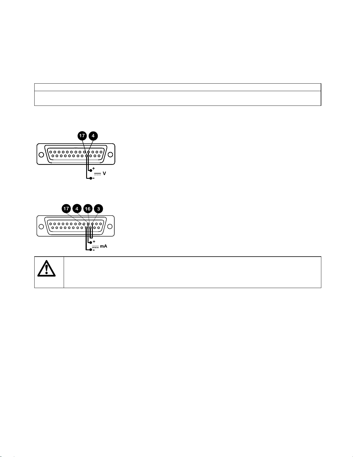
For voltage modes a stable variable DC voltage source can be used in conjunction with a DC voltmeter, (maximum
30V DC). (Refer to 25D pin connector wiring detail as an example of control circuitry) Circuit impedance 100 kohms.
Polarity set for non-inverted response. Reverse polarity for inverted response.
For current modes the same DC source can be used in conjunction with a DC milliampere meter, (maximum 32mA).
(See 25 pin Dee connector detail). Circuit impedance 250 ohms. Polarity set for non-inverted response. Reverse
polarity for inverted response.
key. When the
is the process signal level which has to be reached in order for the pump rotor to start rot ating.
is the change in process signal level necessary to produce the required change in pump rotor speed.
symbol flashes the pump is in manual mode.
AUT
Signal offset Signal range
Never apply mains voltage across any pins on the 25D socket. Up to 30V may be applied across
pins 4 and 17, and 5V TTL on pins 7 and 5, but no voltage should be applied across other pins.
Permanent damage, not covered by warranty may result in both instances. Do not use the mains
power switch to control the pump for a high repetition of stop/starts. The auto-control facility
Calibration procedure
Turn the signal offset potentiometer (marked "Offset" on back panel) clockwise until the slider traverse limit is
reached and is signified by a clicking noise. Now turn the potentiometer te n turns anticlockwise. Repeat for the
signal range potentiometer. This en sures correct potentiomete r set up for calibration.
Set the process signal offset.
Turn the signal offset potentiometer clockwise to set the drive shaft speed to t he desir ed minimum.
Set the process signal at its upper rang e limit (not exceeding 30V or 32mA).
Turn the signal range potentiomete r (marked "Ra nge" on back pa nel) clock wise to set the d rive shaft sp eed to the
desired maximum.
If the process signal or dr ive speed are set above their d esignated maximums the drive will be overloaded wh ich is
signified by the flashing of
operate within these levels.
Repeat the procedure until pump response coincides exactly with the process signal.
should be used.
. This is an indication of the limiting control and speed levels of the drive. Reset to
AUT
4
Page 5

Remote control
Stop/Start
Connect remote switch between pins 7 and 15 of the 25 D connec tor. A TTL compatib le logic input (L ow 0V, High 5V)
may be applied to pin 7. Low input stops th e pump, high input runs the pump. With no connection, the pump will
default to running.
Direction
Connect remote switch between pins 5 and 16 and disable the front panel reversing control by linking pins 6 and 18 of
the 25D connector. Open switch for clockwise rotation, close for counter-clockwise. Alternatively a TTL compatible
logic input (Low 0, High 5V) may be applied to pin 5. Low input will run the pump in a counter-clockwise direction,
High input in a clockwise rotation. No connection; the pump will default to clockwise rotation.
Speed
A remote potentiometer with a nominal value of between 1k and 2k with a minimum of 0.25W should be wired as
shown. When using a remote potentiomete r, do not apply a voltage/cu rrent contro l input signal at th e same time. The
speed control signal will require calibration relative to the minimum and maximum settings of the poten tiometer. Use
the offset and range potentiometers as described under calibration.
Strobe
The state of the pump may be monitored by utilising a 5V Hi Lo signal available at the 25D remote socket on the
pump rear panel. The strobe line will change sta te as soon as the motor starts or stops.
Tachometer output
This facility can be used to indicate motor speed or total the number of motor revolutions.
90rpm 4.8 kHz
5
Page 6

Error messages
If a fault condition is detected in the drive unit it will stop, all keys will be disabled, and the display will flash:
Er1
Er2
Er3
Er4
Er5
Er6
Er9
Care and maintenance
The only scheduled maintenance of the 205S or 205U is to inspect the motor brushes and to replace them b efore
their length is less than 6mm 1/4". The life of the brushes will depend on the duty of the pump, which is expected to be
at least 3,000 hours at maximum speed. When the pump needs cleaning, remove the pumphead and use a mild
solution of detergent in water. Do not use strong solvents.
If the gearbox is rebuilt you should use 15 ml of the recommended lubricant, which is RD-105, this is a SAE 30
mineral oil loaded with molybdenum disulphide to form a soft fluid grease.
205S / 205U Specification
Maximum rotor speed 90rpm
Minimum rotor speed 0.5rpm
Voltage/frequency 100-120/220-240V 50/60Hz
Power consumption 100VA
Shaft Torque 2.2Nm
Operating temperature range 5 to 40C
Storage temperature range -40C to 70C
Weight 3.8kg (8.4Ib)
Noise <70dBA at 1m
Standards IEC 335-1, EN60529 (IP31)
Machinery Directive 2006/42/EC
EMC Directive 2004/108/EC
Pumphead installation
If the pumphead is fitted ignore this section (applicable for all cassette pumpheads).
Remove the planetary gear system cover by pulling gently towards the front of the pumphead.
Apply grease to the drive tongue, align to pumphead centre shaft and locate together.
Tighten the socket head retaining screws at each side of the pumphead with a 5mm A/F ball ended Allen key.
Replace the cover.
EEPROM exhausted error. There is a max i mu m nu mber of times the EEPROM can be written to.
If Er6 is displayed, the EEPRO M must be replaced.
Tachometer fault
Over temperature error
EEPROM error
EEPROM read error
EEPROM write error
RAM corruption error
6
Page 7

Fitting an extension pumphead
Remove the front cover plate.
Remove the end plate using a N o.2 Pozi screwdriver on the first pumphead to expose the two lo cating pins and
drive shaft slot.
Remove the planetary gear system cover from the extension pumph ead.
Fit the extension pumphead onto the two locating pins, ensuring the tongue of its drive shaft aligns with the
pumphead centre shaft.
Tighten the socket head retainin g screws on th e right and left of the extension pu mphead. Fit the end plate to th e
last pumphead and replace the cov e rs.
CA cassette loading
Only use cassettes with manifold tubing.
Place the tube into the tube retaining slots without twisting or stretching it, 1.
Lift the cassette release lever 2.
Load the cassettes into the pumphead, ensuring that they ar e engaged on to the cassette guides at each end, 3.
Ensure that both r etaining lips are engage d and then squeeze the cassette release lever a nd the tube retaining
lug together, until you hear a click, 4.
7
Page 8

CA cassette removal
Lift the cassette release lever and pull out the cassette.
With care, a single cassette can be removed for tube changing without stopping the drive and disturbing the
pumping action of other cassettes.
All cassettes should be in position in the pumphead during normal running, even if some
do not contain tubing. Do not place fingers inside the pumphead.
CA Cassette adjustment and flow rates
Flow rates for pumping water at 20C with zero suction and delivery pressure in PVC tubing, with clockwise
rotation of the pumphead are pu blished at the back of this manual.
Dedicated occlusion adjustment with a vernier indicator has been incorporated into the cassette. This is to enable
repeatable accurate flow rates despite var iations tha t may be caus ed by th e system or w hen pu mping fluids othe r
than water.
The track geometry has been designed so that when the indicator is at the centre position it is indicating the
normal set-up.
To adjust, pull out the adjusting knob and turn. To lock, push back.
Moving the indicator towards the '+' will increase the track occlusion (reduced roller/track gap) enabling higher
pressures to be obtained without a fall off in flow rate.
Moving the indicator towards the '-' wi ll reduc e th e occ lusio n. Remembe r th at high er the o cc lusion, the sho rter th e
tube life.
The mechanism also enables small adjustments in th e flow rate. This is particularly useful when usin g a number
of channels where the inter channel flow rate is critical. As a guide only, one graduation move will vary the flow by
approximately 1%
Care and maintenance
When the pumphead needs c leaning, switch the drive off and isolate it from the mains. Remove the cass ettes from
the pumphead and remove the tubing. Wash the cassettes in water and mild detergent.
If fluid has been spilled into the pumphead, removal of the pumphead from the drive will make cleaning easier.
Periodically, inspect all moving parts for wear and ensure all bearings and rollers are free to rotate.
8
Page 9

Pumphead spares
Number Spare Description
1 DE 0410M End plate
2 DE 0412M Front cover plate
3 DE 0416T Roller 4 way
DE 0417T Roller 8 way
DE 0418T Roller 12 way
DE 0419T Roller 16 way
4a BB 0038 (2 off) Center shaft bearing
4b BB 0014 (2 off) Center spacer bearing
5 DE 0429T Center gear
6 MN 0983M Roller gear
7 OS 0047 Friction O ring
8 DE 0411M Planetary system gear cover
9 BB 0034 (2 per roller) Roller bearing
10 DE 0407M Cassette guide
11 DEA0080A Cassette PVDF (option)
DEA0081A Cassette Acetal (standard)
12 N/A Cassette release lever
9
Page 10

Drive spares
Number Spare Description
1 DEA0065A 205S Control PCB
1 DEA0066A 205U Control PCB
2 DEA0068A Transformer
3 SW 0147 On/Off switch
4 SW 0086 Voltage selector swicth
5 DEA 0062A Motor/gearbox
6 DEA0063A 205S Tacho PCB assembly
6 DEA0064A 205U Tacho PCB ass embly
7 MN 0787A Tacho disc
8 BM0014 Motor brush
9 DEA0067A 205S CPU/Display PCB
9 MNA0431A 205U CPU/Display PCB
DE 0306B/ DE 0307B 205S/ 205U Membrane keypad
FS 0003 Mains fuse 1A T type
Specific drive performance details such as loaded drive speed variation against mains supply voltage fluctuation and
drive stability from a cold start to normal operating temperature are available on request. For further information please
contact Watson-Marlow Technical Support.
10
Page 11

205S/CA and 205U/CA flow rates (ml/min)
Bore mm Bore " 0.5-90rpm Bore mm Bore " 0.5-90rpm
0.13 0.005 0.0006-0.10
0.19 0.007 0.0009-0.16
0.25 0.010 0.0013-0.23
0.38 0.015 0.0036-0.65
0.50 0.020 0.0056-1.01
0.63 0.025 0.0083-1.49
0.76 0.030 0.011-2.02
0.88 0.035 0.016-2.92
1.02 0.040 0.021-3.76
1.14 0.045 0.026-4.68
205 manifold tubing product codes
Bore
mm Bore "
0.13 0.005 984.0013.000
0.19 0.007 984.0019.000
0.25 0.010 978.0025.000 980.0025.000 984.0025.000
0.38 0.015 978.0038.000 980.0038.000 984.0038.000
0.50 0.020 978.0050.000 980.0050.000 984.0050.000 986.0050.000
0.63 0.025 978.0063.000 980.0063.000 982.0063.000 984.0063.000 986.0063.000
0.76 0.030 978.0076.000 980.0076.000 982.0076.000 984.0076.000 986.0076.000
0.88 0.035 978.0088.000 980.0088.000 982.0088.000 984.0088.000 986.0088.000
1.02 0.040 978.0102.000 980.0102.000 982.0102.000 984.0102.000 986.0102.000
1.14 0.045 978.0114.000 980.0114.000 982.0114.000 984.0114.000 986.0114.000
1.29 0.050 978.0129.000 980.0129.000 982.0129.000 984.0129.000 986.0129.000
1.42 0.055 978.0142.000 980.0142.000 982.0142.000 984.0142.000 986.0142.000
1.47 0.058 982.0147.000
1.52 0.060 978.0152.000 980.0152.000 982.0152.000 984.0152.000 986.0152.000
1.65 0.065 978.0165.000 980.0165.000 982.0165.000 984.0165.000 986.0165.000
1.85 0.070 978.0185.000 980.0185.000 982.0185.000 984.0185.000 986.0185.000
2.05 0.080 978.0205.000 980.0205.000 982.0205.000 984.0205.000 986.0205.000
2.38 0.095 978.0238.000 980.0238.000 982.0238.000 984.0238.000 986.0238.000
2.54 0.100 978.0254.000 980.0254.000 982.0254.000 984.0254.000 986.0254.000
2.79 0.110 978.0279.000 980.0279.000 982.0279.000 984.0279.000 986.0279.000
Marprene
PVC
1.29 0.050 0.033-5.95
1.42 0.055 0.040-7.20
1.47 0.058
1.52 0.060 0.043-7.69
1.65 0.065 0.051-9.12
1.85 0.070 0.063-11.3
2.05 0.080 0.076-13.8
2.38 0.095 0.092-16.5
2.54 0.100 0.11-19.3
2.79 0.110 0.12-22.0
Silicone
Solvent
resistant
resistant
Acid
11
Page 12

Outline dimensions
Watson-Marlow, Bioprene
Tygon
Warning, These products are not designed for use in, and should not be used for patient connected
applications.
The information contained in this docu me nt i s believed to be correct but Watson-Marlow Limi te d accepts no liability for
any errors it contains, and reserves the right to alter s pecifications without notice.
is a trademark of the
and
Marprene
Norton
are trademarks of
Company.
Watson-Marlow Limited.
12
Page 13
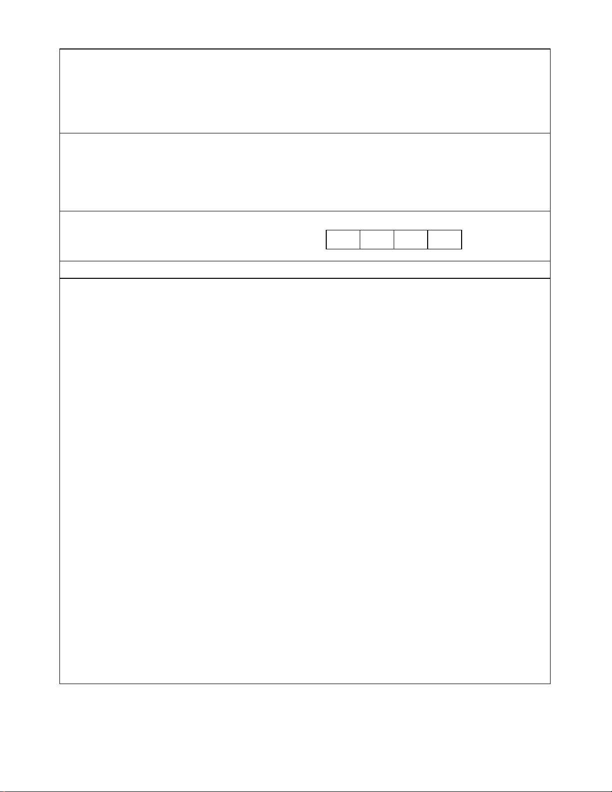
Product use and decontamination declaration
To comply with the UK Health & Safety at Work Act and the Control of Substances Hazardous to Health
Regulations you, the user, are required to declar e the substances w hich have been in contact w ith the product(s)
you are returning to Watson-Marlow or any of its subsidiaries or distributors. Failure to do so will cause delays in
servicing the produc t(s). Please complete this form to ens ure that we have the information before we rec eive the
product(s). A further copy must be attached to the outside of the packaging containing the product(s). The user is
responsible for cleaning and decontaminating the product(s) before ret urn.
Please complete a separate Decontaminat io n Declaration for each pump returned.
1 Company ………………………………………………………………………………………………………………………
Address …………………………………………………………………………………………………………………………
………………….........................................................................Postcode ………………………………………………
Telephone ……………………………………………. ................. Fax Number …………………………………..………
2.1 Serial Number ………………………………………………… (One product per declaration)
2.2 Has the Product been used? Yes No
If yes, please complete all the following Sections. If no, please complete Section 5 only
RGA No:
…………………...
3 Details of substances
pumped
3.1 Chemical names:
(a)……………… .........................
(b)…………….............................
(c)……………… .........................
3.2 Precautions to be taken in handling these substances: To assist servicing, please describe any fault
(a) ………………………………………………………………… condition(s) you have witnessed
(b) ………………………………………………………………… .........................................……………………………
(c) …………………………………………………………………
3.3 Action to be taken in the event of human contact:
(a)………………………………………………………………….
……………………………………………………………
(b)………………………………………………………………….
……………………………………………………………
4 I confirm that the only substances(s) t h at the equipment specified has pumped
or come into contact with are those named, that the information given is
correct, and the carrier has been informed if t he consig nment is of a hazardous
nature.
5 Signed ………………………………………………………………
Name ………………………………………………………………
Position ………………………………………………………………
Date …………………………………………………………………
(c)………….………………………………………………………
3.4 Cleaning fluid to be used if residue of chemical is found: ……………………………………………………………
(a)………………………………………………………………….
……………………………………………………………
(b)………………………………………………………………….
……………………………………………………………
(c)………….………………………………………………………
Watson-Marlow Bredel Pumps . Falmouth . Cornwall TR11 4RU . England . Tel: 01326 370370 . Fax : 01326 376009
13
 Loading...