


 MagicSpeed MS900
(Model no. MS-902)
DE |
9 |
Geschwindigkeitsregler |
|
NL |
62 |
Automatische cruise control |
|
|
Montageanleitung |
|
|
|
Montagehandleiding |
EN |
20 |
Cruise control |
|
DA |
72 |
Automatisk hastighedsregulering |
|
|
Installation Manual |
|
|
|
Monteringsvejledning |
FR |
31 |
Régulateur de automatique de |
|
SV |
82 |
Automatisk hastighetsregulator |
|
|
vitesse |
|
|
|
Monteringsanvisning |
|
|
Instructions de montage |
|
|
|
|
ES |
41 |
Regulador de velocidad automático |
|
NO |
92 |
Automatisk hastighetskontroll |
|
|
Instrucciones de montaje |
|
|
|
Monteringsanvisning |
IT |
51 |
Regolatore de velocità automatico |
|
FI |
102 |
Automaattinen nopeudensäädin |
|
|
Indicazioni di montaggio |
|
|
|
Asennusohje |
|
|
|
|
|
|
|
D
Fordern Sie weitere Informationen zur umfangreichen Produktpalette aus dem Hause WAECO an. Bestellen Sie einfach unsere Kataloge kostenlos und unverbindlich unter der Internetadresse: www.waeco.de
GB
We will be happy to provide you with further information about WAECO products. Please order our free catalogue with no obligation to buy on our homepage: www.waeco.com
F
Demandez d’autres informations relatives à la large gamme de produits de la maison WAECO. Commandez tout simplement notre catalogue gratuitement et sans engagement à l’adresse internet suivante : www.waeco.com
E
Solicite más información sobre la amplia gama de productos de la empresa WAECO. Solicite simplemente nuestros catálogos de forma gratuita y sin compromiso en la dirección de Internet: www.waeco.com
I
Per ottenere maggiori informazioni sull’ampia gamma di prodotti WAECO è possibile ordinare una copia gratuita e non vincolante del nostro Catalogo all’indirizzo Internet: www.waeco.com
NL
Maak kennis met het omvangrijke productscala van de firma WAECO. Bestel onze catalogus gratis en vrijblijvend onder het internetadres: www.waeco.com
DK
Bestil yderligere information om det omfattende produktudvalg fra WAECO. Bestil vores katalog gratis og uforpligtende på internetadressen: www.waeco.com
S
Inhämta mer information om den omfattande produktpaletten från WAECO: Beställ våra kataloger gratis och utan förpliktelser under vår Internetadress: www.waeco.com
N
Be om mer informasjon om det rikholdige produktutvalget fra WAECO. Bestill vår katalog gratis uforbindtlig på Internettadressen: www.waeco.com
FIN
Pyytäkää lisää tietoja WAECOn kattavista tuotevalikoimista. Tilatkaa tuotekuvastomme maksutta ja sitoumuksetta internet-osoitteesta: www.waeco.com
MagicSpeed |
|
|
|
|
1 |
1 |
2 |
3 |
4 |
|
5 |
|
6 |
8 |
|
|
|
7 |
|
|
|
|
|
|
|
|
|
|
9 |
2 |
|
|
3 |
|
3
MagicSpeed
4
1
2
5
1
4
MagicSpeed |
|
|
6 |
|
|
|
|
A |
2 |
|
|
|
1 |
|
7 |
|
|
|
|
pu/rt |
3 |
2 |
1 |
|
|
|
|
|
bl |
|
|
4 |
5

|
MagicSpeed |
8 |
3 |
|
|
ws/rt |
|
1 |
2 |
|
|
4 |
pk |
|
|
9 |
|
ge/rt
1 2 
 3
3
4
rt
6
MagicSpeed
0
1
a
1 2
b
1
2 3
7
MagicSpeed
c
ge/rt (+15)
1 |
|
ws/rt (CAN High) |
4 |
6 |
|
2 |
pu/rt (CAN Low) |
14 |
7  6
6
5
3
1
|
bl |
ge |
pk |
pu |
rt |
ws |
|
|
|
|
|
|
|
D |
Blau |
Gelb |
Pink |
Purpur |
Rot |
Weiss |
|
|
|
|
|
|
|
|
|
|
|
|
|
|
GB |
Blue |
Yellow |
|
|
Red |
White |
|
|
|
|
|
|
|
F |
Bleu |
Jaune |
|
|
Rouge |
Blanc |
|
|
|
|
|
|
|
E |
Azul |
Amarillo |
|
|
Rojo |
Blanco |
|
|
|
|
|
|
|
|
|
|
|
|
|
|
I |
Blu |
Giallo |
|
|
Rosso |
Bianco |
|
|
|
|
|
|
|
NL |
Blauw |
Geel |
|
|
Rood |
Wit |
|
|
|
|
|
|
|
DK |
Blå |
Gul |
|
|
Rød |
Hvid |
|
|
|
|
|
|
|
|
|
|
|
|
|
|
S |
Blå |
Gul |
|
|
Röd |
Vit |
|
|
|
|
|
|
|
N |
Blå |
Gul |
|
|
Rød |
Hvit |
|
|
|
|
|
|
|
FIN |
Sininen |
Keltainen |
|
|
Punainen |
Valkoinen |
|
|
|
|
|
|
|
|
|
|
|
|
|
|
8

MagicSpeed |
Hinweise zur Benutzung der Anleitung |
Bitte lesen Sie diese Anleitung vor Einbau und Inbetriebnahme sorgfältig durch und bewahren Sie sie auf. Geben Sie sie im Falle einer Weitergabe des Gerätes an den Nutzer weiter.
Inhaltsverzeichnis
1 Hinweise zur Benutzung der Anleitung . . . . . . . . . . . . . . . . . . . . . . . 9 2 Sicherheitsund Einbauhinweise. . . . . . . . . . . . . . . . . . . . . . . . . . . 10 3 Lieferumfang . . . . . . . . . . . . . . . . . . . . . . . . . . . . . . . . . . . . . . . . . . 11 4 Bestimmungsgemäßer Gebrauch . . . . . . . . . . . . . . . . . . . . . . . . . . 12 5 Technische Beschreibung . . . . . . . . . . . . . . . . . . . . . . . . . . . . . . . . 12 6 MagicSpeed montieren . . . . . . . . . . . . . . . . . . . . . . . . . . . . . . . . . . 13 7 MagicSpeed elektrisch anschließen . . . . . . . . . . . . . . . . . . . . . . . . 15 8 Gewährleistung . . . . . . . . . . . . . . . . . . . . . . . . . . . . . . . . . . . . . . . . 18 9 Entsorgung. . . . . . . . . . . . . . . . . . . . . . . . . . . . . . . . . . . . . . . . . . . . 18
10 Technische Daten . . . . . . . . . . . . . . . . . . . . . . . . . . . . . . . . . . . . . . 19
1 Hinweise zur Benutzung der Anleitung
aSicherheitshinweis: Nichtbeachtung kann zu Materialschäden führen und die Funktion des Gerätes beeinträchtigen.Achtung!
eSicherheitshinweis, der auf Gefahren mit elektrischem Strom oder elektrischer Spannung hinweist: Nichtbeachtung kann zu Perso-
nenoder Materialschäden führen und die Funktion des Gerätes beeinträchtigen.Achtung!
Hinweis
I Ergänzende Informationen zur Bedienung des Gerätes.
Handlung: Dieses Symbol zeigt Ihnen, dass Sie etwas tun müssen. Die erforderlichen Handlungen werden Schritt für Schritt beschrieben.
9

Sicherheitsund Einbauhinweise |
MagicSpeed |
Dieses Symbol beschreibt das Ergebnis einer Handlung.
Abb. 1 5, Seite 3: Diese Angabe weist Sie auf ein Element in einer Abbildung hin, in diesem Beispiel auf „Position 5 in Abbildung 1 auf Seite 3“.
Beachten Sie bitte auch die nachfolgenden Sicherheitshinweise.
2 Sicherheitsund Einbauhinweise
Beachten Sie die vom Fahrzeughersteller und vom Kfz-Handwerk vorgeschriebenen Sicherheitshinweise und Auflagen!
WAECO International übernimmt keine Haftung für Schäden aufgrund folgender Punkte:
zMontagefehler,
zBeschädigungen am Gerät durch mechanische Einflüsse und Überspannungen,
zVeränderungen am Gerät ohne ausdrücklicher Genehmigung von WAECO International,
zVerwendung für andere als die in der Anleitung beschriebenen Zwecke.
eKlemmen Sie wegen der Kurzschlussgefahr vor Arbeiten an der Fahrzeugelektrik immer den Minuspol ab.
Bei Fahrzeugen mit Zusatzbatterie müssen Sie an dieser ebenfalls den Minuspol abklemmen.
Achtung!
eUnzureichende Leitungsverbindungen können zur Folge haben, dass durch Kurzschluss
–Kabelbrände entstehen,
–der Airbag ausgelöst wird,
–elektronische Steuerungseinrichtungen beschädigt werden,
–elektrische Funktionen ausfallen (Blinker, Bremslicht, Hupe, Zündung, Licht).Achtung!
Beim Abklemmen des Minuspols der Batterie verlieren alle flüchtigen Speicher der Komfortelektronik ihre gespeicherten Daten.
10
MagicSpeed |
Lieferumfang |
Beachten Sie folgende Hinweise bei der Montage:
zBefestigen Sie die im Fahrzeug montierten Teile von MagicSpeed so, dass sie sich unter keinen Umständen (scharfes Abbremsen, Verkehrsunfall) lösen und zu Verletzungen der Fahrzeuginsassen führen können.
zAchten Sie darauf, dass der Fahrer zur Bedienung nicht durch das Lenkrad greifen muss.
zAchten Sie beim Bohren auf ausreichenden Freiraum für den Bohreraustritt, um Schäden zu vermeiden (Abb. 2, Seite 3).
Beachten Sie folgende Hinweise bei der Arbeit an elektrischen Teilen:
zBeachten Sie beim Verlegen der elektrischen Anschlüsse (Abb. 3, Seite 3), dass diese
–nicht geknickt oder verdreht werden,
–nicht an Kanten scheuern,
–nicht ohne Schutz durch scharfkantige Durchführungen verlegt werden.
zSichern Sie die Kabel gegen mechanische Beanspruchung durch Kabelbinder oder Isolierband, z. B. an vorhandenen Leitungen.
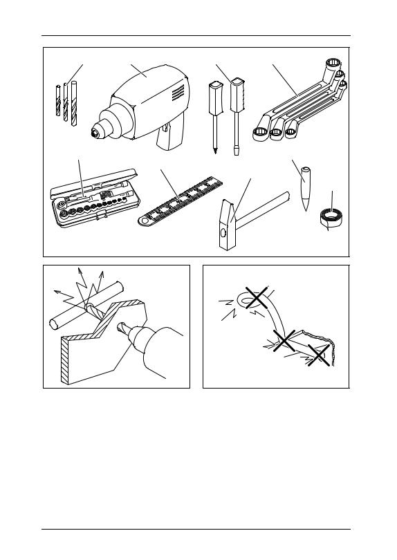
3 Lieferumfang
Nr. in
Abb. 4, Menge Bezeichnung
Seite 4 |
|
|
1 |
1 |
Elektronikmodul |
2 |
1 |
Hauptkabelsatz |
– |
– |
Befestigungsmaterial |
11

Bestimmungsgemäßer Gebrauch |
MagicSpeed |
4 Bestimmungsgemäßer Gebrauch
MagicSpeed MS900 (Art.-Nr. MS-902) ist ein Geschwindigkeitsregler, der die eingestellte Geschwindigkeit möglichst konstant beibehält. Er vergleicht die tatsächliche Geschwindigkeit mit Ihrer Wunschgeschwindigkeit und korrigiert ggf. die tatsächliche Geschwindigkeit.
MagicSpeed ist zum Einbau in folgende Nutzfahrzeuge ausgelegt:
zOpel Movano
zOpel Vivaro
zRenault Master (ab 2005)
zRenault Traffic (ab 2005)
zNissan Primastar (ab 2006)
zNissan Interstar (ab 2006)
5 Technische Beschreibung
MagicSpeed MS900 besteht aus einem Elektronikmodul, das an den CANBus und das elektronische Gaspedal des Fahrzeugs angeschlossen wird und über ein Bedienelement betätigt wird.
IBeachten Sie die Einbauund Bedienungsanleitung des Bedienelementes.Hinweis
Das Elektronikmodul misst die tatsächliche Geschwindigkeit und vergleicht diese mit Ihrer Wunschgeschwindigkeit.
12

MagicSpeed |
MagicSpeed montieren |
6 MagicSpeed montieren
6.1Benötigtes Werkzeug
Für Einbau und Montage benötigen Sie folgende Werkzeuge:
zSatz Bohrer (Abb. 1 1, Seite 3)
zBohrmaschine (Abb. 1 2, Seite 3)
zSchraubendreher (Abb. 1 3, Seite 3)
zSatz Ringoder Maulschlüssel (Abb. 1 4, Seite 3)
zSteckschlüsselsatz (Abb. 1 5, Seite 3)
zMaßstab (Abb. 1 6, Seite 3)
zHammer (Abb. 1 7, Seite 3)
zKörner (Abb. 1 8, Seite 3)
Für den elektrischen Anschluss und seine Überprüfung benötigen Sie folgende Hilfsmittel:
zIsolierband (Abb. 1 9, Seite 3)
zDichtungsmasse
zGgf. Kabeldurchführungstüllen
Zur Befestigung der Module und der Kabel benötigen Sie ggf. noch weitere Schrauben und Kabelbinder.
13

MagicSpeed montieren |
MagicSpeed |
6.2Elektronikmodul montieren
Hinweis
I Beachten Sie bei der Wahl des Montageortes folgende Hinweise:
zMontieren Sie das Elektronikmodul
–in der Nähe des CAN-Bus-Diagnosesteckers,
–nicht an Orten mit großem Hitzeaufkommen oder Feuchtigkeit,
–nicht im Motorraum,
–nicht in der Nähe von Hochspannung führenden Bauteilen,
–nicht direkt an Luftaustrittsdüsen.
zNutzen Sie möglichst vorhandene Bohrungen im Fahrzeug.
aÜberprüfen Sie vor dem Bohren immer die Austrittsseite auf freien Durchgang (Abb. 2, Seite 3).Achtung!
Wählen Sie einen geeigneten Montageort (Abb. 5, Seite 4).
ISie können das Elektonikmodul mit den beiliegenden Schrauben befestigen oder doppelseitiges Klebeband verwenden.Hinweis
Installieren Sie das Elektronikmodul provisorisch an der gewählten Position.
Befestigen Sie das Elektronikmodul nicht, bevor Sie die Kabelführung festgelegt haben.
Nach Abschluss der Verkabelung befestigen Sie das Modul an der gewählten Position:
–Befestigen Sie das Elektronikmodul mit doppelseitigem Klebeband oder …
–Markieren Sie die Löcher für die Montage.
–Bohren Sie zwei Löcher mit einem Durchmesser von 3 mm.
–Schrauben Sie das Elektonikmodul mit den beiliegenden Schrauben fest.
14

MagicSpeed |
MagicSpeed elektrisch anschließen |
7 MagicSpeed elektrisch anschließen
7.1Allgemeine Hinweise zur Kabelverlegung
IVerwenden Sie für die Durchführung der Anschlusskabel nach Möglichkeit Originaldurchführungen oder andere Durchführungsmöglichkeiten, z. B. Verkleidungskanten, Lüftungsgitter oder Blindschalter. Wenn keine Durchführungen vorhanden sind, müssen Sie für die jeweiligen Kabel entsprechende Löcher bohren. Schauen Sie vorher nach, ob ausreichender Freiraum für den Bohreraustritt vorhanden ist.
Hinweis
INicht fachgerechte Kabelverlegungen und Kabelverbindungen führen immer wieder zu Fehlfunktionen oder Beschädigungen von Bauteilen. Eine korrekte Kabelverlegung und Kabelverbindung ist
die Grundvoraussetzung für eine dauerhafte und fehlerfreie Funktion der nachgerüsteten Komponenten.Hinweis
Beachten Sie deshalb folgende Hinweise:
zUm Beschädigungen am Kabel zu vermeiden, halten Sie beim Verlegen der Kabel immer ausreichend Abstand zu heißen und sich bewegenden Fahrzeugteilen (Auspuffrohre, Antriebswellen, Lichtmaschine, Lüfter, Heizung usw.).
zBeachten Sie beim Verlegen der Kabel, dass diese
–nicht stark geknickt oder verdreht werden,
–nicht an Kanten scheuern,
–nicht ohne Schutz durch scharfkantige Durchführungen verlegt werden (Abb. 3, Seite 3).
zSchützen Sie jeden Durchbruch durch geeignete Maßnahmen gegen Wassereinbruch, z. B. durch Einsetzen des Kabels mit Dichtungsmasse und durch Abspritzen des Kabels und der Durchführungstülle mit Dichtungsmasse.
15

MagicSpeed elektrisch anschließen |
MagicSpeed |
7.2Kabel verlegen und anschließen
Einen Überblick über die gesamte Verschaltung finden Sie in Abb. c, Seite 8.
Nr. |
Bauteil |
|
Nr. |
Bauteil |
|
|
|
|
|
1 |
Elektronikmodul |
5 |
Anschluss Hauptkabelsatz |
|
|
|
|
|
|
2 |
Diagnosestecker |
|
6 |
Anschluss CAN-Bus |
|
|
|
|
|
3 |
Hauptkabelsatz |
7 |
Anschluss Bedienelement |
|
4Fahrzeugeigene CAN-Bus- Leitung
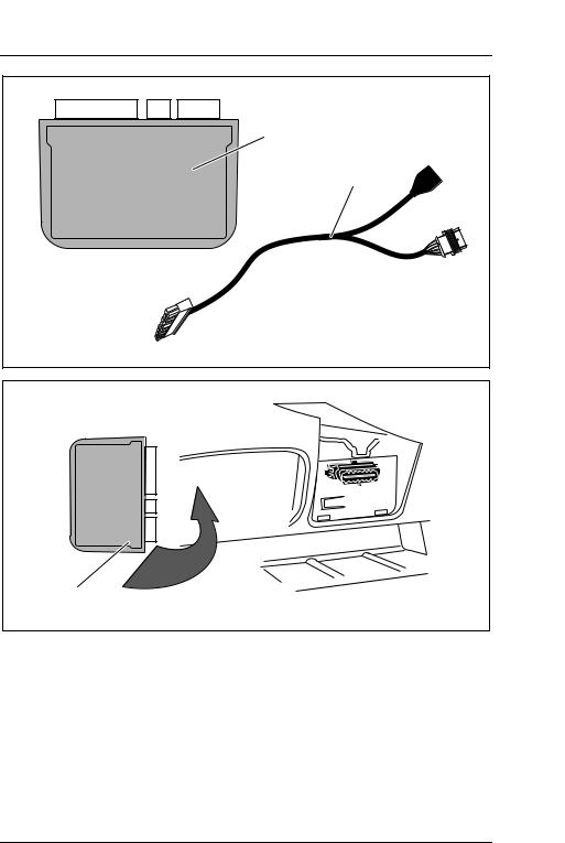
Kabelsatz für CAN-Bus anschließen
Klemmen Sie die Batterie ab.
Ziehen Sie die Stecksicherung (Abb. 6 2, Seite 5) vom Diagnosestecker (Abb. 6 2, Seite 5) ab.
Sie können nun die Adern mit einem Schraubendreher lösen (Abb. 6 A, Seite 5).
Schließen Sie die blaue Leitung des CAN-Bus-Kabelsatzes an (Abb. 7, Seite 5):
–purpur/rote Ader (1) aus Steckplatz 14 des Diagnosesteckers lösen
–purpur/rote Ader (1) mit blauer Ader (2) des CAN-Bus-Kabelsatzes verbinden
–Verbindung durch Isoliertülle (3) schützen
–blaue Ader (4) des CAN-Bus-Kabelsatzes in Steckplatz 14 des Diagnosesteckers stecken
Schließen Sie die pinkfarbene Leitung des CAN-Bus-Kabelsatzes an (Abb. 8, Seite 6):
–weiß/rote Ader (1) aus Steckplatz 6 des Diagnosesteckers lösen
–weiß/rote Ader (1) mit pinkfarbener Ader (2) des CAN-Bus- Kabelsatzes verbinden
–Verbindung durch Isoliertülle (3) schützen
–pinkfarbene Ader (4) des CAN-Bus-Kabelsatzes in Steckplatz 6 des Diagnosesteckers stecken
16

MagicSpeed |
MagicSpeed elektrisch anschließen |
Schließen Sie die rote Leitung des CAN-Bus-Kabelsatzes an (Abb. 9, Seite 6):
–gelb/rote Ader (1) aus Steckplatz 1 des Diagnosesteckers lösen
–gelb/rote Ader (1) mit roter Ader (2) des CAN-Bus-Kabelsatzes verbinden
–Verbindung durch Isoliertülle (3) schützen
–rote Ader (4) des CAN-Bus-Kabelsatzes in Steckplatz 1 des Diagnosesteckers stecken
Stecken Sie die Stecksicherung (Abb. 0 1, Seite 7) auf den Diagnosestecker.
Hauptkabelsatz anschließen
Lösen Sie den fahrzeugeigenen Stecker (Abb. a 1, Seite 7) vom Gaspedal (Abb. a 2, Seite 7).
Schließen Sie den Hauptkabelsatz an das Gaspedal an (Abb. b, Seite 7):
–Stecker des Hauptkabelsatz (1) auf das Gaspedal stecken
–fahrzeugeigenen Stecker (2) auf Buchse (3) des Hauptkabelsatz stecken
Elektronikmodul anschließen
Stecken Sie den 16-poligen Stecker des Hauptkabelsatzes auf die Buchse des Elektronikmoduls (Abb. c 5, Seite 8).
Stecken Sie den 4-poligen Stecker des CAN-Busses auf die Buchse des Elektronikmoduls (Abb. c 6, Seite 8).
Stecken Sie den 8-poligen Stecker des Bedienelementes auf die Buchse des Elektronikmoduls (Abb. c 7, Seite 8).
Klemmen Sie die Batterie an.
17

Gewährleistung |
MagicSpeed |
8 Gewährleistung
Es gilt die gesetzliche Gewährleistungsfrist. Sollte das Produkt defekt sein, schicken Sie es bitte an die WAECO Niederlassung in Ihrem Land (Adressen siehe Rückseite der Anleitung) oder an Ihren Fachhändler. Zur Reparaturbzw. Gewährleistungsbearbeitung müssen Sie folgende Unterlagen mitschicken:
zeine Kopie der Rechnung mit Kaufdatum,
zeinen Reklamationsgrund oder eine Fehlerbeschreibung.
9 Entsorgung
Geben Sie das Verpackungsmaterial möglichst in den entsprechenden Recycling-Müll.
Wenn Sie das Gerät endgültig außer Betrieb nehmen, informieren Sie sich bitte beim nächsten Recyclingcenter oder bei Ihrem Fachhändler über die zutreffenden Entsorgungsvorschriften.
18

MagicSpeed |
Technische Daten |
|
10 |
Technische Daten |
|
|
|
|
Art.-Nr.: |
|
MS-902 |
|
|
|
Fahrzeugtyp: |
Opel Movano |
|
|
|
Opel Vivaro |
|
|
Renault Master (ab 2005) |
|
|
Renault Traffic (ab 2005) |
|
|
Nissan Primastar (ab 2006) |
|
|
Nissan Interstar (ab 2006) |
|
|
|
Betriebsspannung: |
12 Volt |
|
|
|
|
Leistungsaufnahme: |
max. 20 mAh |
|
|
|
|
Betriebstemperatur: |
–40 °C bis +85 °C |
|
|
|
|
ABE Nr. |
|
ABE90989 |
|
|
|
Ausführungen, dem technischen Fortschritt dienende Änderungen und Liefermöglichkeiten vorbehalten.
Zulassungen
Das Gerät hat die e11-Zulassung.

 11
11
19

Notes on using the manual |
MagicSpeed |
Please read this instruction manual carefully before installing and starting up the device, and store it in a safe place. If the device is handed over to another person, this operating manual must be handed over along with it.
Contents
1 Notes on using the manual . . . . . . . . . . . . . . . . . . . . . . . . . . . . . . . 20 2 Safety and installation instructions. . . . . . . . . . . . . . . . . . . . . . . . . . 21 3 Scope of delivery . . . . . . . . . . . . . . . . . . . . . . . . . . . . . . . . . . . . . . . 22 4 Intended use . . . . . . . . . . . . . . . . . . . . . . . . . . . . . . . . . . . . . . . . . . 23 5 Technical description . . . . . . . . . . . . . . . . . . . . . . . . . . . . . . . . . . . . 23 6 MagicSpeed installation . . . . . . . . . . . . . . . . . . . . . . . . . . . . . . . . . . 24 7 Connecting the electrical power to MagicSpeed . . . . . . . . . . . . . . . 26 8 Guarantee . . . . . . . . . . . . . . . . . . . . . . . . . . . . . . . . . . . . . . . . . . . . 29 9 Disposal . . . . . . . . . . . . . . . . . . . . . . . . . . . . . . . . . . . . . . . . . . . . . . 29
10 Technical data . . . . . . . . . . . . . . . . . . . . . . . . . . . . . . . . . . . . . . . . . 30
1 Notes on using the manual
aSafety instruction: Failure to observe this instruction can cause material damage and impair the function of the device.Caution
eSafety instruction relating to a danger from electrical current or voltage. Failure to observe this instruction can cause material damage or personal injury and impair the function of the device.Caution
Note
I Additional information on the operation of the device.
Action: This symbol indicates that action is required on your part. The required action is described step-by-step.
20
MagicSpeed |
Safety and installation instructions |
This symbol describes the result of an action.
fig. 1 5, page 3: This refers to an element in an illustration. In this case, “item 5 in figure 1 on page 3”.
Please also observe the following safety instructions.
2 Safety and installation instructions
Please observe the prescribed safety instructions and stipulations from the vehicle manufacturer and service workshops.
WAECO International will not be held liable for claims for damage resulting from the following:
zInstallation errors
zDamage to the device resulting from mechanical influences or excess voltage
zAlterations made to the device without the explicit permission of WAECO International
zUse for purposes other than those described in the operating manual
eTo prevent the risk of short circuits, always disconnect the negative terminal of the vehicle's electrical system before working on it.
If the vehicle has an additional battery, its negative terminal should also be disconnected.
Caution
eInadequatecausing: supply cable connections could result in short circuits,
–Cable fires
–The airbag being triggered
–Damage to electronic control equipment
–Electrical malfunctions (indicators, brake light, horn, ignition, lights)Caution
If you disconnect the negative terminal of the battery, all data stored in the volatile memories will be lost.
21

Scope of delivery |
MagicSpeed |
Observe the following installation instructions:
zSecure the MagicSpeed components installed in the vehicle in such a way that they cannot become loose under any circumstances (sudden braking, accidents) and cause injuries to the occupants of the vehicle.
zMake sure the driver does not have to reach through the steering wheel to operate it.
zTo prevent damage when drilling, check that there is sufficient space on the other side for the drill head to come out (fig. 2, page 3).
Observe the following instructions when working with electrical parts:
zWhen making electrical connections (fig. 3, page 3), ensure that:
–They are not kinked or twisted
–They do not rub on edges
–They are not laid in sharp-edged ducts without protection
zProtect the cables from mechanical wear (for example rubbing against existing cables) using cable binders or insulating tape.
3 Scope of delivery
No. in
fig. 4, Quantity Description page 4
11 Electronic module
21 Main wiring harness
–– Fastening material
22

MagicSpeed |
Intended use |
4 Intended use
MagicSpeed MS900 (Item no. MS-902) is a speed regulator which maintains a constant set speed. It compares the actual speed to the set speed and corrects it if necessary.
MagicSpeed is designed for installation in the following commercial vehicles:
zOpel Movano
zOpel Vivaro
zRenault Master (from 2005)
zRenault Traffic (from 2005)
zNissan Primastar (from 2006)
zNissan Interstar (from 2006)
5 Technical description
MagicSpeed MS900 consists of an electronic module, which is connected to the CAN-Bus and the vehicle's electronic accelerator, and is operated using a control element.
Note
I Observement. the installation and operating manual for the control ele-
The electronic module measures the current speed and compares it to the set speed.
23

MagicSpeed installation |
MagicSpeed |
6 MagicSpeed installation
6.1Tools required
For installation and assembly you will need the following tools:
zDrill bit set (fig. 1 1, page 3)
zDrill (fig. 1 2, page 3)
zScrewdriver (fig. 1 3, page 3)
zSet of ring or open-ended spanners (see fig. 1 4, page 3)
zSet of box spanners (fig. 1 5, page 3)
zMeasuring ruler (fig. 1 6, page 3)
zHammer (fig. 1 7, page 3)
zCentre punch (fig. 1 8, page 3)
To establish and test the electrical connection, the following tools are required:
zInsulating tape (fig. 1 9, page 3)
zSealant
zCable bushing sleeves (optional)
To fasten the module and the cables, you may need additional screws and cable binders.
24

MagicSpeed |
MagicSpeed installation |
6.2Fitting the electronic module
IWhen selecting the installation location, observe the following instructions:Note
zInstall the electronic module
–Near the CAN-Bus diagnostic plug
–Not anywhere subject to heat or moisture
–Not in the engine compartment
–Not near high-voltage components
–Not directly next to ventilator nozzles
zWhere possible, use existing holes in the vehicle.
aBefore drilling holes, make sure the bit will not damage anything on the other side (fig. 2, page 3).Caution
Select a suitable installation location (fig. 5, page 4).
IThe electronic module can be attached to the vehicle using the screws supplied or double-sided adhesive tape.Note
Temporarily mount the electronic module at the selected position.
Do not fasten the electronic module before you have decided where to lay the cables.
After finishing the electric wiring, fasten the module in the selected position:
–Fasten the electronic module using double-sided tape or ...
–Mark the holes for installation.
–Drill two holes with 3 mm diameters.
–Tightly fasten the electronic module using the screws provided.
25

Connecting the electrical power to MagicSpeed |
MagicSpeed |
7Connecting the electrical power to MagicSpeed
7.1General notes on laying cables
IAs far as possible, use original ducts for laying the cables, or other suitable options, such as panelling edges, ventilation grilles or dummy plugs. If no openings are available, you must drill holes for the cables. Check beforehand that there is sufficient space on the other side for the drill head to come out.
Note
ICables and connections that are not properly installed will cause malfunctions or damage to components. Correct installation of ca-
bles and connections ensures lasting and trouble-free operation of the retrofitted components.Note
Therefore, please observe the following instructions:
zTo prevent damage to the cables, when laying them, ensure that they are far enough away from hot or moving vehicle components (exhaust pipes, drive shafts, light systems, fans, heater etc.).
zWhen laying the cables, make sure:
–They are not kinked or twisted
–They do not rub on edges
–They are not laid through sharp-edged ducts without protection (fig. 3, page 3)
zProtect every hole you drill against water penetration, e.g. by using a cable with a sealant and by spraying the cable and the the cable sleeve with sealant.
26

MagicSpeed |
Connecting the electrical power to MagicSpeed |
7.2Laying and connecting the cable
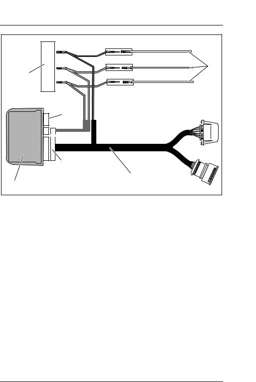
You will find a summary of the wiring in fig. c, page 8.
No. |
Component |
|
No. |
Component |
|
|
|
|
|
1 |
Electronic module |
5 |
Main wiring harness con- |
|
|
|
|
|
nection |
|
|
|
|
|
2 |
Diagnostic plug |
|
6 |
CAN bus connection |
|
|
|
|
|
3 |
Main wiring harness |
7 |
Control element connection |
|
|
|
|
|
|
4 |
Vehicle CAN bus wire |
|
|
|
|
|
|
|
|
Connecting the wiring harness for the CAN bus
Disconnect the battery.
Pull the plug protector (fig. 6 2, page 5) off the diagnostic plug (fig. 6 2, page 5).
The wires can now be disconnected with a screwdriver (fig. 6 A, page 5).
Connect the blue wire of the CAN bus wiring harness (fig. 7, page 5):
–Disconnect the purple/red wire (1) from socket 14 of the diagnostic plug
–Connect the purple/red wire (1) to the blue wire (2) of the CAN bus wiring harness
–Protect the connection using an insulating sleeve (3)
–Connect the blue wire (4) of the CAN bus wiring harness to socket 14 of the diagnostic plug
Connect the pink wire of the CAN bus wiring harness (fig. 8, page 6):
–Disconnect the white/red wire (1) from socket 6 of the diagnostic plug
–Connect the white/red wire (1) to the pink wire (2) of the CAN bus wiring harness
–Protect the connection using an insulating sleeve (3)
–Connect the pink wire (4) of the CAN wiring harness to socket 6 of the diagnostic plug
27

Connecting the electrical power to MagicSpeed |
MagicSpeed |
Connect the red wire of the CAN bus wiring harness (fig. 9, page 6):
–Disconnect the yellow/red wire (1) from socket 1 of the diagnostic plug
–Connect the yellow/red wire (1) to the red wire (2) of the CAN bus wiring harness
–Protect the connection using an insulating sleeve (3)
–Connect the red wire (4) of the CAN bus wiring harness to socket 1 of the diagnostic plug
Put the plug protector (fig. 0 1, page 7) onto the diagnostic plug.
Connecting the main wiring harness
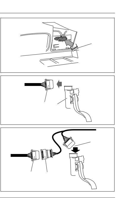
Disconnect the vehicle's plug (fig. a 1, page 7) from the accelerator pedal (fig. a 2, page 7).
Connect the main wiring harness to the accelerator pedal (fig. b, page 7):
–Connect the plug of the main wiring harness (1) to the accelerator pedal
–Connect the vehicle's plug (2) to the socket (3) on the main wiring harness
Connecting the electronic module
Insert the 16-pin plug on the main wiring harness into the socket on the electronic module (fig. c 5, page 8).
Insert the 4-pin plug on the CAN bus into the socket on the electronic module (fig. c 6, page 8).
Insert the 8-pin plug of the control element into the socket on the electronic module (fig. c 7, page 8).
Connect the battery.
28
MagicSpeed |
Guarantee |
8 Guarantee
The statutory warranty period applies. Should the product be defective, please return it to the WAECO branch in your country (see the back of the instruction manual for the addresses) or to your local dealer. For repairs and warranty claims, you must submit the following documents:
zA copy of the receipt with purchasing date
zA reason for the claim or description of the fault
9 Disposal
If possible, always dispose of the packaging material in the appropriate recycling container.
If you wish to finally dispose of the device, ask your local recycling centre or specialist dealer for details about how to do this in accordance with the applicable disposal regulations.
29

Technical data |
MagicSpeed |
|
10 |
Technical data |
|
|
|
|
Item no.: |
|
MS-902 |
|
|
|
Vehicle type: |
Opel Movano |
|
|
|
Opel Vivaro |
|
|
Renault Master (from 2005) |
|
|
Renault Traffic (from 2005) |
|
|
Nissan Primastar (from 2006) |
|
|
Nissan Interstar (from 2006) |
|
|
|
Operating voltage: |
12 volts |
|
|
|
|
Power consumption: |
max. 20 mAh |
|
|
|
|
Operating temperature: |
–40 °C to +85 °C |
|
|
|
|
ABE no.: |
|
ABE90989 |
|
|
|
Variations, technical improvements and delivery options reserved.
Certification
The appliance has e11 certification.

 11
11
30
 Loading...