

Service
Workshop Manual
Touareg 2018 ➤
6-cyl. direct injection (3.0 l, 4V, EA 839,
turbocharger)
Engine ID
Edition 11.2020
DCB
E
Service Department. Technical Information

List of Workshop Manual Repair Groups
Re pa ir G ro up
00 - Technical data
10 - Removing and installing engine
13 - Crankshaft group
15 - Cylinder head, valve gear
17 - Lubrication
19 - Cooling
21 - Turbocharging/supercharging
24 - Mixture preparation - injection
26 - Exhaust system
28 - Ignition system
93 - Electric drive systems
Service
Technical information should always be available to the foremen and mechanics, because their
careful and constant adherence to the instructions is essential to ensure vehicle road-worthiness
and safety. In addition, the normal basic safety precautions for working on motor vehicles must, as
a matter of course, be observed.

Touareg 2018 ➤
6-cyl. direct injection (3.0 l, 4V, EA 839, turbocharger) - Edition 11.2020
Contents
00 - Technical data . . . . . . . . . . . . . . . . . . . . . . . . . . . . . . . . . . . . . . . . . . . . . . . . . . . . 1
1 Safety information . . . . . . . . . . . . . . . . . . . . . . . . . . . . . . . . . . . . . . . . . . . . . . . . . . . . . . . . 1
1.1 Safety precautions when working on high-voltage system . . . . . . . . . . . . . . . . . . . . . . . . . . 1
1.2 Safety precautions when working in the vicinity of high-voltage components . . . . . . . . . . 2
1.3 Safety regulations for working on fuel supply . . . . . . . . . . . . . . . . . . . . . . . . . . . . . . . . . . . . 2
1.4 Safety measures when working on vehicles with a start/stop system . . . . . . . . . . . . . . . . 3
1.5 Safety precautions when using testers and measuring instruments during a road test . . . . 3
1.6 Safety precautions when working on subframe . . . . . . . . . . . . . . . . . . . . . . . . . . . . . . . . . . 3
1.7 Safety precautions when working on ignition system . . . . . . . . . . . . . . . . . . . . . . . . . . . . . . 3
1.8 Safety precautions when working on the cooling system . . . . . . . . . . . . . . . . . . . . . . . . . . 4
1.9 Safety precautions when working on exhaust system . . . . . . . . . . . . . . . . . . . . . . . . . . . . 4
2 Identification . . . . . . . . . . . . . . . . . . . . . . . . . . . . . . . . . . . . . . . . . . . . . . . . . . . . . . . . . . . . 5
2.1 Engine number/engine data . . . . . . . . . . . . . . . . . . . . . . . . . . . . . . . . . . . . . . . . . . . . . . . . 5
2.2 Numbering of cylinders . . . . . . . . . . . . . . . . . . . . . . . . . . . . . . . . . . . . . . . . . . . . . . . . . . . . 6
3 Repair instructions . . . . . . . . . . . . . . . . . . . . . . . . . . . . . . . . . . . . . . . . . . . . . . . . . . . . . . . . 7
3.1 Rules for cleanliness . . . . . . . . . . . . . . . . . . . . . . . . . . . . . . . . . . . . . . . . . . . . . . . . . . . . . . 7
3.2 Foreign objects in engine . . . . . . . . . . . . . . . . . . . . . . . . . . . . . . . . . . . . . . . . . . . . . . . . . . 7
3.3 Contact corrosion . . . . . . . . . . . . . . . . . . . . . . . . . . . . . . . . . . . . . . . . . . . . . . . . . . . . . . . . 7
3.4 Routing and attachment of lines . . . . . . . . . . . . . . . . . . . . . . . . . . . . . . . . . . . . . . . . . . . . . . 8
3.5 Fitting radiator and condensers . . . . . . . . . . . . . . . . . . . . . . . . . . . . . . . . . . . . . . . . . . . . . . 8
3.6 Checking fuel system for leaks . . . . . . . . . . . . . . . . . . . . . . . . . . . . . . . . . . . . . . . . . . . . . . 8
4 Hazard classification of high-voltage system . . . . . . . . . . . . . . . . . . . . . . . . . . . . . . . . . . . . 9
10 - Removing and installing engine . . . . . . . . . . . . . . . . . . . . . . . . . . . . . . . . . . . . . . 16
1 Removing and installing engine . . . . . . . . . . . . . . . . . . . . . . . . . . . . . . . . . . . . . . . . . . . . . . 16
1.1 Removing engine . . . . . . . . . . . . . . . . . . . . . . . . . . . . . . . . . . . . . . . . . . . . . . . . . . . . . . . . 16
1.2 Separating engine and gearbox . . . . . . . . . . . . . . . . . . . . . . . . . . . . . . . . . . . . . . . . . . . . . . 49
1.3 Removing engine from scissor-type assembly platform . . . . . . . . . . . . . . . . . . . . . . . . . . . . 57
1.4 Securing engine on engine and gearbox support . . . . . . . . . . . . . . . . . . . . . . . . . . . . . . . . 58
1.5 Installing engine . . . . . . . . . . . . . . . . . . . . . . . . . . . . . . . . . . . . . . . . . . . . . . . . . . . . . . . . . . 61
2 Assembly mountings . . . . . . . . . . . . . . . . . . . . . . . . . . . . . . . . . . . . . . . . . . . . . . . . . . . . . . 68
2.1 Assembly overview – assembly mountings . . . . . . . . . . . . . . . . . . . . . . . . . . . . . . . . . . . . 68
2.2 Supporting engine in installation position . . . . . . . . . . . . . . . . . . . . . . . . . . . . . . . . . . . . . . 74
2.3 Removing and installing engine mounting . . . . . . . . . . . . . . . . . . . . . . . . . . . . . . . . . . . . . . 75
2.4 Removing and installing gearbox mounting . . . . . . . . . . . . . . . . . . . . . . . . . . . . . . . . . . . . 79
2.5 Removing and installing power unit mounting senders . . . . . . . . . . . . . . . . . . . . . . . . . . . . 84
2.6 Calibrating electrohydraulic engine mounting . . . . . . . . . . . . . . . . . . . . . . . . . . . . . . . . . . 84
3 Engine cover panel . . . . . . . . . . . . . . . . . . . . . . . . . . . . . . . . . . . . . . . . . . . . . . . . . . . . . . . . 86
3.1 Removing and installing engine cover . . . . . . . . . . . . . . . . . . . . . . . . . . . . . . . . . . . . . . . . 86
13 - Crankshaft group . . . . . . . . . . . . . . . . . . . . . . . . . . . . . . . . . . . . . . . . . . . . . . . . . . 87
1 Cylinder block (pulley end) . . . . . . . . . . . . . . . . . . . . . . . . . . . . . . . . . . . . . . . . . . . . . . . . . . 87
1.1 Assembly overview - cylinder block (pulley end) . . . . . . . . . . . . . . . . . . . . . . . . . . . . . . . . 87
1.2 Assembly overview - sealing flange, belt pulley end . . . . . . . . . . . . . . . . . . . . . . . . . . . . . . 93
1.3 Removing and installing poly-V belt . . . . . . . . . . . . . . . . . . . . . . . . . . . . . . . . . . . . . . . . . . 95
1.4 Removing and installing tensioner for poly V-belt . . . . . . . . . . . . . . . . . . . . . . . . . . . . . . . . 99
1.5 Removing and installing vibration damper . . . . . . . . . . . . . . . . . . . . . . . . . . . . . . . . . . . . . . 101
1.6 Removing and installing bracket for ancillaries . . . . . . . . . . . . . . . . . . . . . . . . . . . . . . . . . . 106
1.7 Removing and installing engine support . . . . . . . . . . . . . . . . . . . . . . . . . . . . . . . . . . . . . . 107
1.8 Renewing crankshaft oil seal - belt pulley end . . . . . . . . . . . . . . . . . . . . . . . . . . . . . . . . . . 108
1.9 Removing and installing sealing flange on pulley end . . . . . . . . . . . . . . . . . . . . . . . . . . . . 110
2 Cylinder block, gearbox end . . . . . . . . . . . . . . . . . . . . . . . . . . . . . . . . . . . . . . . . . . . . . . . . 115
Contents i

Touareg 2018 ➤
6-cyl. direct injection (3.0 l, 4V, EA 839, turbocharger) - Edition 11.2020
2.1 Assembly overview - cylinder block, gearbox end . . . . . . . . . . . . . . . . . . . . . . . . . . . . . . . . 115
2.2 Removing and installing drive plate . . . . . . . . . . . . . . . . . . . . . . . . . . . . . . . . . . . . . . . . . . 115
2.3 Renewing crankshaft oil seal (gearbox end) . . . . . . . . . . . . . . . . . . . . . . . . . . . . . . . . . . . . 117
3 Crankshaft . . . . . . . . . . . . . . . . . . . . . . . . . . . . . . . . . . . . . . . . . . . . . . . . . . . . . . . . . . . . . . 120
3.1 Assembly overview - crankshaft . . . . . . . . . . . . . . . . . . . . . . . . . . . . . . . . . . . . . . . . . . . . . . 120
3.2 Crankshaft dimensions . . . . . . . . . . . . . . . . . . . . . . . . . . . . . . . . . . . . . . . . . . . . . . . . . . . . 123
3.3 Allocation of main bearing shells . . . . . . . . . . . . . . . . . . . . . . . . . . . . . . . . . . . . . . . . . . . . 123
3.4 Measuring axial clearance of crankshaft . . . . . . . . . . . . . . . . . . . . . . . . . . . . . . . . . . . . . . 125
3.5 Measuring radial clearance of crankshaft . . . . . . . . . . . . . . . . . . . . . . . . . . . . . . . . . . . . . . 126
3.6 Removing and installing sender wheel . . . . . . . . . . . . . . . . . . . . . . . . . . . . . . . . . . . . . . . . 126
3.7 Checking sender wheel . . . . . . . . . . . . . . . . . . . . . . . . . . . . . . . . . . . . . . . . . . . . . . . . . . . . 127
3.8 Removing and installing crankshaft . . . . . . . . . . . . . . . . . . . . . . . . . . . . . . . . . . . . . . . . . . 128
4 Balancer shaft . . . . . . . . . . . . . . . . . . . . . . . . . . . . . . . . . . . . . . . . . . . . . . . . . . . . . . . . . . 132
4.1 Assembly overview - balance shaft . . . . . . . . . . . . . . . . . . . . . . . . . . . . . . . . . . . . . . . . . . 132
4.2 Removing and installing balance shaft . . . . . . . . . . . . . . . . . . . . . . . . . . . . . . . . . . . . . . . . 132
5 Pistons and conrods . . . . . . . . . . . . . . . . . . . . . . . . . . . . . . . . . . . . . . . . . . . . . . . . . . . . . . 138
5.1 Assembly overview - pistons and conrods . . . . . . . . . . . . . . . . . . . . . . . . . . . . . . . . . . . . . . 138
5.2 Removing and installing pistons . . . . . . . . . . . . . . . . . . . . . . . . . . . . . . . . . . . . . . . . . . . . . . 143
5.3 Removing and installing oil spray jets . . . . . . . . . . . . . . . . . . . . . . . . . . . . . . . . . . . . . . . . 147
5.4 Checking pistons and cylinder bores . . . . . . . . . . . . . . . . . . . . . . . . . . . . . . . . . . . . . . . . . . 148
5.5 Checking radial clearance of conrods . . . . . . . . . . . . . . . . . . . . . . . . . . . . . . . . . . . . . . . . 150
15 - Cylinder head, valve gear . . . . . . . . . . . . . . . . . . . . . . . . . . . . . . . . . . . . . . . . . . 152
1 Cylinder head . . . . . . . . . . . . . . . . . . . . . . . . . . . . . . . . . . . . . . . . . . . . . . . . . . . . . . . . . . . . 152
1.1 Assembly overview - cylinder head . . . . . . . . . . . . . . . . . . . . . . . . . . . . . . . . . . . . . . . . . . 152
1.2 Assembly overview - camshaft housing . . . . . . . . . . . . . . . . . . . . . . . . . . . . . . . . . . . . . . . . 156
1.3 Removing and installing cylinder head . . . . . . . . . . . . . . . . . . . . . . . . . . . . . . . . . . . . . . . . 159
1.4 Removing and installing camshaft housing . . . . . . . . . . . . . . . . . . . . . . . . . . . . . . . . . . . . 168
1.5 Checking compression . . . . . . . . . . . . . . . . . . . . . . . . . . . . . . . . . . . . . . . . . . . . . . . . . . . . 181
2 Cover for timing chain . . . . . . . . . . . . . . . . . . . . . . . . . . . . . . . . . . . . . . . . . . . . . . . . . . . . 183
2.1 Assembly overview - cover for timing chain . . . . . . . . . . . . . . . . . . . . . . . . . . . . . . . . . . . . 183
2.2 Removing and installing timing chain cover . . . . . . . . . . . . . . . . . . . . . . . . . . . . . . . . . . . . 186
3 Chain drive . . . . . . . . . . . . . . . . . . . . . . . . . . . . . . . . . . . . . . . . . . . . . . . . . . . . . . . . . . . . . . 197
3.1 Assembly overview - camshaft timing chains . . . . . . . . . . . . . . . . . . . . . . . . . . . . . . . . . . . . 197
3.2 Assembly overview - drive chain for oil pump . . . . . . . . . . . . . . . . . . . . . . . . . . . . . . . . . . 201
3.3 Removing camshaft timing chain from camshafts . . . . . . . . . . . . . . . . . . . . . . . . . . . . . . . . 202
3.4 Removing and installing camshaft timing chain . . . . . . . . . . . . . . . . . . . . . . . . . . . . . . . . . . 228
3.5 Removing and installing chain tensioner . . . . . . . . . . . . . . . . . . . . . . . . . . . . . . . . . . . . . . 229
4 Valve gear . . . . . . . . . . . . . . . . . . . . . . . . . . . . . . . . . . . . . . . . . . . . . . . . . . . . . . . . . . . . . . 233
4.1 Assembly overview - valve gear . . . . . . . . . . . . . . . . . . . . . . . . . . . . . . . . . . . . . . . . . . . . . . 233
4.2 Measuring axial play of camshaft . . . . . . . . . . . . . . . . . . . . . . . . . . . . . . . . . . . . . . . . . . . . 236
4.3 Measuring radial play of camshaft . . . . . . . . . . . . . . . . . . . . . . . . . . . . . . . . . . . . . . . . . . . . 237
4.4 Removing and installing camshaft . . . . . . . . . . . . . . . . . . . . . . . . . . . . . . . . . . . . . . . . . . . . 238
4.5 Removing and installing cam actuators . . . . . . . . . . . . . . . . . . . . . . . . . . . . . . . . . . . . . . . . 240
4.6 Removing and installing camshaft control valve 1 N205 . . . . . . . . . . . . . . . . . . . . . . . . . . 243
4.7 Removing and installing valve stem seals . . . . . . . . . . . . . . . . . . . . . . . . . . . . . . . . . . . . . . 243
5 Inlet and exhaust valves . . . . . . . . . . . . . . . . . . . . . . . . . . . . . . . . . . . . . . . . . . . . . . . . . . . . 258
5.1 Checking valve guides . . . . . . . . . . . . . . . . . . . . . . . . . . . . . . . . . . . . . . . . . . . . . . . . . . . . 258
5.2 Checking valves . . . . . . . . . . . . . . . . . . . . . . . . . . . . . . . . . . . . . . . . . . . . . . . . . . . . . . . . . . 259
5.3 Valve dimensions . . . . . . . . . . . . . . . . . . . . . . . . . . . . . . . . . . . . . . . . . . . . . . . . . . . . . . . . 259
17 - Lubrication . . . . . . . . . . . . . . . . . . . . . . . . . . . . . . . . . . . . . . . . . . . . . . . . . . . . . . 260
1 Sump, oil pump . . . . . . . . . . . . . . . . . . . . . . . . . . . . . . . . . . . . . . . . . . . . . . . . . . . . . . . . . . 260
1.1 Assembly overview - sump/oil pump . . . . . . . . . . . . . . . . . . . . . . . . . . . . . . . . . . . . . . . . . . 260
1.2 Engine oil: . . . . . . . . . . . . . . . . . . . . . . . . . . . . . . . . . . . . . . . . . . . . . . . . . . . . . . . . . . . . . . 265
ii Contents

Touareg 2018 ➤
6-cyl. direct injection (3.0 l, 4V, EA 839, turbocharger) - Edition 11.2020
1.3 Removing and installing lower part of sump . . . . . . . . . . . . . . . . . . . . . . . . . . . . . . . . . . . . 266
1.4 Removing and installing upper part of sump . . . . . . . . . . . . . . . . . . . . . . . . . . . . . . . . . . . . 269
1.5 Removing and installing oil baffle plate . . . . . . . . . . . . . . . . . . . . . . . . . . . . . . . . . . . . . . . . 276
1.6 Removing and installing oil pump . . . . . . . . . . . . . . . . . . . . . . . . . . . . . . . . . . . . . . . . . . . . 278
1.7 Removing and installing oil level and oil temperature sender G266 . . . . . . . . . . . . . . . . . . 280
2 Engine oil cooler . . . . . . . . . . . . . . . . . . . . . . . . . . . . . . . . . . . . . . . . . . . . . . . . . . . . . . . . . . 281
2.1 Assembly overview - engine oil cooler . . . . . . . . . . . . . . . . . . . . . . . . . . . . . . . . . . . . . . . . 281
2.2 Removing and installing engine oil cooler . . . . . . . . . . . . . . . . . . . . . . . . . . . . . . . . . . . . . . 281
2.3 Removing and installing spray nozzle valve . . . . . . . . . . . . . . . . . . . . . . . . . . . . . . . . . . . . 284
3 Crankcase ventilation . . . . . . . . . . . . . . . . . . . . . . . . . . . . . . . . . . . . . . . . . . . . . . . . . . . . . . 286
3.1 Assembly overview - crankcase breather system . . . . . . . . . . . . . . . . . . . . . . . . . . . . . . . . 286
3.2 Removing and installing crankcase breather module . . . . . . . . . . . . . . . . . . . . . . . . . . . . . . 287
4 Oil filter, oil pressure switch . . . . . . . . . . . . . . . . . . . . . . . . . . . . . . . . . . . . . . . . . . . . . . . . 289
4.1 Assembly overview - oil filter . . . . . . . . . . . . . . . . . . . . . . . . . . . . . . . . . . . . . . . . . . . . . . . . 289
4.2 Assembly overview - oil pressure switches/oil pressure control . . . . . . . . . . . . . . . . . . . . . . 291
4.3 Removing and installing oil pressure switch F22 . . . . . . . . . . . . . . . . . . . . . . . . . . . . . . . . 292
4.4 Removing and installingoil temperature sender G8 . . . . . . . . . . . . . . . . . . . . . . . . . . . . . . 293
4.5 Checking oil pressure . . . . . . . . . . . . . . . . . . . . . . . . . . . . . . . . . . . . . . . . . . . . . . . . . . . . . . 294
4.6 Removing and installing oil filter housing . . . . . . . . . . . . . . . . . . . . . . . . . . . . . . . . . . . . . . 295
4.7 Removing and installing oil pressure regulating valve N428 . . . . . . . . . . . . . . . . . . . . . . . . 297
4.8 Removing and installing oil pressure sender G10 . . . . . . . . . . . . . . . . . . . . . . . . . . . . . . . . 298
19 - Cooling . . . . . . . . . . . . . . . . . . . . . . . . . . . . . . . . . . . . . . . . . . . . . . . . . . . . . . . . . . 300
1 Cooling system/coolant . . . . . . . . . . . . . . . . . . . . . . . . . . . . . . . . . . . . . . . . . . . . . . . . . . . . 300
1.1 Connection diagram - coolant hoses . . . . . . . . . . . . . . . . . . . . . . . . . . . . . . . . . . . . . . . . . . 300
1.2 Overview of fitting locations – cooling system . . . . . . . . . . . . . . . . . . . . . . . . . . . . . . . . . . 308
1.3 Assembly overview – coolant expansion tank . . . . . . . . . . . . . . . . . . . . . . . . . . . . . . . . . . 311
1.4 Checking cooling system for leaks . . . . . . . . . . . . . . . . . . . . . . . . . . . . . . . . . . . . . . . . . . . . 313
1.5 Draining and adding coolant . . . . . . . . . . . . . . . . . . . . . . . . . . . . . . . . . . . . . . . . . . . . . . . . 323
1.6 Removing and installing coolant expansion tank . . . . . . . . . . . . . . . . . . . . . . . . . . . . . . . . 349
2 Coolant pump, regulation of cooling system . . . . . . . . . . . . . . . . . . . . . . . . . . . . . . . . . . . . 355
2.1 Assembly overview - coolant pump, thermostat . . . . . . . . . . . . . . . . . . . . . . . . . . . . . . . . . . 355
2.2 Assembly overview - electric coolant pump . . . . . . . . . . . . . . . . . . . . . . . . . . . . . . . . . . . . 357
2.3 Assembly overview - coolant temperature sender . . . . . . . . . . . . . . . . . . . . . . . . . . . . . . . . 359
2.4 Assembly overview – coolant valves . . . . . . . . . . . . . . . . . . . . . . . . . . . . . . . . . . . . . . . . . . 363
2.5 Removing and installing electric coolant pump . . . . . . . . . . . . . . . . . . . . . . . . . . . . . . . . . . 365
2.6 Removing and installing coolant pump . . . . . . . . . . . . . . . . . . . . . . . . . . . . . . . . . . . . . . . . 371
2.7 Removing and installing map-controlled engine cooling thermostat F265 . . . . . . . . . . . . . . 372
2.8 Removing and installing coolant temperature sender G62 . . . . . . . . . . . . . . . . . . . . . . . . 374
2.9 Removing and installing engine outlet coolant temperature sender G82 . . . . . . . . . . . . . . 375
2.10 Removing and installing radiator outlet coolant temperature sender G83 . . . . . . . . . . . . . . 377
2.11 Removing and installing temperature sender for engine temperature regulation G694 . . . . 380
2.12 Removing and installing coolant valves . . . . . . . . . . . . . . . . . . . . . . . . . . . . . . . . . . . . . . . . 381
2.13 Removing and installing coolant temperature sender for high-voltage system . . . . . . . . . . 387
3 Coolant pipes . . . . . . . . . . . . . . . . . . . . . . . . . . . . . . . . . . . . . . . . . . . . . . . . . . . . . . . . . . . . 397
3.1 Assembly overview - coolant pipes . . . . . . . . . . . . . . . . . . . . . . . . . . . . . . . . . . . . . . . . . . 397
3.2 Removing and installing coolant pipes . . . . . . . . . . . . . . . . . . . . . . . . . . . . . . . . . . . . . . . . 399
4 Radiator, radiator fan . . . . . . . . . . . . . . . . . . . . . . . . . . . . . . . . . . . . . . . . . . . . . . . . . . . . . . 407
4.1 Assembly overview – radiator, radiator fan . . . . . . . . . . . . . . . . . . . . . . . . . . . . . . . . . . . . 407
4.2 Removing and installing radiator . . . . . . . . . . . . . . . . . . . . . . . . . . . . . . . . . . . . . . . . . . . . 412
4.3 Removing and installing radiator cowl . . . . . . . . . . . . . . . . . . . . . . . . . . . . . . . . . . . . . . . . 417
4.4 Removing and installing radiator fan V7 . . . . . . . . . . . . . . . . . . . . . . . . . . . . . . . . . . . . . . . . 422
4.5 Removing and installing radiator for high-voltage system coolant circuit . . . . . . . . . . . . . . 422
4.6 Removing and installing air ducts . . . . . . . . . . . . . . . . . . . . . . . . . . . . . . . . . . . . . . . . . . . . 425
Contents iii

Touareg 2018 ➤
6-cyl. direct injection (3.0 l, 4V, EA 839, turbocharger) - Edition 11.2020
21 - Turbocharging/supercharging . . . . . . . . . . . . . . . . . . . . . . . . . . . . . . . . . . . . . . . . 430
1 Turbocharger . . . . . . . . . . . . . . . . . . . . . . . . . . . . . . . . . . . . . . . . . . . . . . . . . . . . . . . . . . . . 430
1.1 Assembly overview - turbocharger . . . . . . . . . . . . . . . . . . . . . . . . . . . . . . . . . . . . . . . . . . . . 430
1.2 Removing and installing turbocharger . . . . . . . . . . . . . . . . . . . . . . . . . . . . . . . . . . . . . . . . 435
1.3 Renewing vacuum unit for turbocharger . . . . . . . . . . . . . . . . . . . . . . . . . . . . . . . . . . . . . . 441
1.4 Removing and installing temperature sender for engine cover panel G765 . . . . . . . . . . . . 447
2 Charge air system . . . . . . . . . . . . . . . . . . . . . . . . . . . . . . . . . . . . . . . . . . . . . . . . . . . . . . . . 448
2.1 Assembly overview - charge air system . . . . . . . . . . . . . . . . . . . . . . . . . . . . . . . . . . . . . . . . 448
2.2 Assembly overview - charge-air hose connections . . . . . . . . . . . . . . . . . . . . . . . . . . . . . . 453
2.3 Removing and installing air pipe . . . . . . . . . . . . . . . . . . . . . . . . . . . . . . . . . . . . . . . . . . . . 454
2.4 Removing and installing pressure pipe . . . . . . . . . . . . . . . . . . . . . . . . . . . . . . . . . . . . . . . . 457
2.5 Removing and installing charge air cooler . . . . . . . . . . . . . . . . . . . . . . . . . . . . . . . . . . . . . . 461
2.6 Removing and installing charge pressure sender G31 . . . . . . . . . . . . . . . . . . . . . . . . . . . . 464
2.7 Removing and installing overrun air recirculation valve . . . . . . . . . . . . . . . . . . . . . . . . . . . . 465
2.8 Checking charge air system for leaks . . . . . . . . . . . . . . . . . . . . . . . . . . . . . . . . . . . . . . . . 465
24 - Mixture preparation - injection . . . . . . . . . . . . . . . . . . . . . . . . . . . . . . . . . . . . . . . . 468
1 Injection system . . . . . . . . . . . . . . . . . . . . . . . . . . . . . . . . . . . . . . . . . . . . . . . . . . . . . . . . . . 468
1.1 Overview of fitting locations - injection system . . . . . . . . . . . . . . . . . . . . . . . . . . . . . . . . . . 468
1.2 Checking fuel system for leaks . . . . . . . . . . . . . . . . . . . . . . . . . . . . . . . . . . . . . . . . . . . . . . 478
2 Vacuum system . . . . . . . . . . . . . . . . . . . . . . . . . . . . . . . . . . . . . . . . . . . . . . . . . . . . . . . . . . 479
2.1 Connection diagram - vacuum system . . . . . . . . . . . . . . . . . . . . . . . . . . . . . . . . . . . . . . . . 479
2.2 Checking vacuum system . . . . . . . . . . . . . . . . . . . . . . . . . . . . . . . . . . . . . . . . . . . . . . . . . . 479
3 Injectors . . . . . . . . . . . . . . . . . . . . . . . . . . . . . . . . . . . . . . . . . . . . . . . . . . . . . . . . . . . . . . . . 481
3.1 Assembly overview - fuel rail with injectors . . . . . . . . . . . . . . . . . . . . . . . . . . . . . . . . . . . . 481
3.2 Removing and installing fuel rail . . . . . . . . . . . . . . . . . . . . . . . . . . . . . . . . . . . . . . . . . . . . . . 483
3.3 Removing and installing injectors . . . . . . . . . . . . . . . . . . . . . . . . . . . . . . . . . . . . . . . . . . . . 485
3.4 Cleaning injectors . . . . . . . . . . . . . . . . . . . . . . . . . . . . . . . . . . . . . . . . . . . . . . . . . . . . . . . . 491
4 Air filter . . . . . . . . . . . . . . . . . . . . . . . . . . . . . . . . . . . . . . . . . . . . . . . . . . . . . . . . . . . . . . . . 494
4.1 Assembly overview - air filter housing . . . . . . . . . . . . . . . . . . . . . . . . . . . . . . . . . . . . . . . . 494
4.2 Removing and installing air filter housing . . . . . . . . . . . . . . . . . . . . . . . . . . . . . . . . . . . . . . 495
5 Intake manifold . . . . . . . . . . . . . . . . . . . . . . . . . . . . . . . . . . . . . . . . . . . . . . . . . . . . . . . . . . 497
5.1 Assembly overview – intake manifold . . . . . . . . . . . . . . . . . . . . . . . . . . . . . . . . . . . . . . . . . . 497
5.2 Removing and installing intake manifold . . . . . . . . . . . . . . . . . . . . . . . . . . . . . . . . . . . . . . 498
5.3 Removing and installing throttle valve module J338 . . . . . . . . . . . . . . . . . . . . . . . . . . . . . . 501
5.4 Cleaning throttle valve module . . . . . . . . . . . . . . . . . . . . . . . . . . . . . . . . . . . . . . . . . . . . . . 503
6 Senders and sensors . . . . . . . . . . . . . . . . . . . . . . . . . . . . . . . . . . . . . . . . . . . . . . . . . . . . . . 505
6.1 Assembly overview - actuator for structure-borne sound and control unit for structure-borne
sound . . . . . . . . . . . . . . . . . . . . . . . . . . . . . . . . . . . . . . . . . . . . . . . . . . . . . . . . . . . . . . . . . . 505
6.2 Assembly overview - pressure differential sender, models with particulate filter . . . . . . . . 506
6.3 Removing and installing actuator for structure-borne sound R214 . . . . . . . . . . . . . . . . . . 507
6.4 Removing and installing control unit for structure-borne sound J869 . . . . . . . . . . . . . . . . 508
6.5 Removing and installing intake manifold sender GX9 . . . . . . . . . . . . . . . . . . . . . . . . . . . . 508
6.6 Removing and installing fuel pressure sender G247 . . . . . . . . . . . . . . . . . . . . . . . . . . . . . . 509
6.7 Removing and installing fuel pressure sender for low-pressure G410 . . . . . . . . . . . . . . . . 510
6.8 Removing and installing pressure differential sender for particulate filter G1037, models
with particulate filter (petrol) . . . . . . . . . . . . . . . . . . . . . . . . . . . . . . . . . . . . . . . . . . . . . . . . 510
7 Engine control unit . . . . . . . . . . . . . . . . . . . . . . . . . . . . . . . . . . . . . . . . . . . . . . . . . . . . . . . . 514
7.1 Assembly overview – motor control unit . . . . . . . . . . . . . . . . . . . . . . . . . . . . . . . . . . . . . . . . 514
7.2 Removing and installing engine control unit J623 . . . . . . . . . . . . . . . . . . . . . . . . . . . . . . . . 514
8 High-pressure pump . . . . . . . . . . . . . . . . . . . . . . . . . . . . . . . . . . . . . . . . . . . . . . . . . . . . . . 516
8.1 Assembly overview - high-pressure pump . . . . . . . . . . . . . . . . . . . . . . . . . . . . . . . . . . . . . . 516
8.2 Removing and installing high-pressure pump . . . . . . . . . . . . . . . . . . . . . . . . . . . . . . . . . . 520
8.3 Removing and installing high-pressure pipe . . . . . . . . . . . . . . . . . . . . . . . . . . . . . . . . . . . . 523
iv Contents

Touareg 2018 ➤
6-cyl. direct injection (3.0 l, 4V, EA 839, turbocharger) - Edition 11.2020
9 Lambda probe . . . . . . . . . . . . . . . . . . . . . . . . . . . . . . . . . . . . . . . . . . . . . . . . . . . . . . . . . . 527
9.1 Assembly overview - Lambda probe . . . . . . . . . . . . . . . . . . . . . . . . . . . . . . . . . . . . . . . . . . 527
9.2 Removing and installing Lambda probe . . . . . . . . . . . . . . . . . . . . . . . . . . . . . . . . . . . . . . . . 528
26 - Exhaust system . . . . . . . . . . . . . . . . . . . . . . . . . . . . . . . . . . . . . . . . . . . . . . . . . . 533
1 Exhaust pipes and silencers . . . . . . . . . . . . . . . . . . . . . . . . . . . . . . . . . . . . . . . . . . . . . . . . 533
1.1 Assembly overview – silencers . . . . . . . . . . . . . . . . . . . . . . . . . . . . . . . . . . . . . . . . . . . . . . 533
1.2 Removing and installing front silencer . . . . . . . . . . . . . . . . . . . . . . . . . . . . . . . . . . . . . . . . 540
1.3 Separating exhaust pipes from silencers . . . . . . . . . . . . . . . . . . . . . . . . . . . . . . . . . . . . . . 543
1.4 Removing and installing silencer . . . . . . . . . . . . . . . . . . . . . . . . . . . . . . . . . . . . . . . . . . . . 544
1.5 Aligning exhaust system free of stress . . . . . . . . . . . . . . . . . . . . . . . . . . . . . . . . . . . . . . . . 545
1.6 Checking exhaust system for leaks . . . . . . . . . . . . . . . . . . . . . . . . . . . . . . . . . . . . . . . . . . 546
2 Emission control . . . . . . . . . . . . . . . . . . . . . . . . . . . . . . . . . . . . . . . . . . . . . . . . . . . . . . . . . . 547
2.1 Assembly overview – emission control . . . . . . . . . . . . . . . . . . . . . . . . . . . . . . . . . . . . . . . . 547
2.2 Removing and installing catalytic converter . . . . . . . . . . . . . . . . . . . . . . . . . . . . . . . . . . . . 550
2.3 Removing and installing particulate filter . . . . . . . . . . . . . . . . . . . . . . . . . . . . . . . . . . . . . . 551
3 Exhaust gas temperature regulation . . . . . . . . . . . . . . . . . . . . . . . . . . . . . . . . . . . . . . . . . . 554
3.1 Removing and installing exhaust gas temperature sender 3 G495 . . . . . . . . . . . . . . . . . . 554
28 - Ignition system . . . . . . . . . . . . . . . . . . . . . . . . . . . . . . . . . . . . . . . . . . . . . . . . . . . . 556
1 Ignition system . . . . . . . . . . . . . . . . . . . . . . . . . . . . . . . . . . . . . . . . . . . . . . . . . . . . . . . . . . 556
1.1 Assembly overview - ignition system . . . . . . . . . . . . . . . . . . . . . . . . . . . . . . . . . . . . . . . . . . 556
1.2 Removing and installing ignition coils with output stage . . . . . . . . . . . . . . . . . . . . . . . . . . 558
1.3 Removing and installing knock sensor 1 G61 . . . . . . . . . . . . . . . . . . . . . . . . . . . . . . . . . . 562
1.4 Removing and installing Hall sender . . . . . . . . . . . . . . . . . . . . . . . . . . . . . . . . . . . . . . . . . . 563
1.5 Removing and installing engine speed sender G28 . . . . . . . . . . . . . . . . . . . . . . . . . . . . . . 564
93 - Electric drive systems . . . . . . . . . . . . . . . . . . . . . . . . . . . . . . . . . . . . . . . . . . . . . . 566
1 High-voltage components . . . . . . . . . . . . . . . . . . . . . . . . . . . . . . . . . . . . . . . . . . . . . . . . . . 566
1.1 Overview of fitting locations - high-voltage components . . . . . . . . . . . . . . . . . . . . . . . . . . 566
2 Warning stickers . . . . . . . . . . . . . . . . . . . . . . . . . . . . . . . . . . . . . . . . . . . . . . . . . . . . . . . . . . 569
2.1 Checking warning stickers . . . . . . . . . . . . . . . . . . . . . . . . . . . . . . . . . . . . . . . . . . . . . . . . . . 569
3 High-voltage battery unit . . . . . . . . . . . . . . . . . . . . . . . . . . . . . . . . . . . . . . . . . . . . . . . . . . 573
3.1 Assembly overview – high-voltage battery . . . . . . . . . . . . . . . . . . . . . . . . . . . . . . . . . . . . . . 573
3.2 Visual inspection of high-voltage battery 1 AX2 . . . . . . . . . . . . . . . . . . . . . . . . . . . . . . . . . . 575
3.3 Diagnosing high-voltage battery 1 AX2 . . . . . . . . . . . . . . . . . . . . . . . . . . . . . . . . . . . . . . . . 576
3.4 Searching for leaks from high-voltage battery . . . . . . . . . . . . . . . . . . . . . . . . . . . . . . . . . . 577
3.5 Removing and installing high-voltage battery 1 AX2 . . . . . . . . . . . . . . . . . . . . . . . . . . . . . . 584
3.6 Removing and installing battery regulation control unit J840 . . . . . . . . . . . . . . . . . . . . . . . . 593
3.7 Removing and installing switching unit for high-voltage battery SX6 . . . . . . . . . . . . . . . . . . 594
4 High-voltage battery components . . . . . . . . . . . . . . . . . . . . . . . . . . . . . . . . . . . . . . . . . . . . 597
4.1 Assembly overview – high-voltage battery . . . . . . . . . . . . . . . . . . . . . . . . . . . . . . . . . . . . . . 597
4.2 Overview of fitting locations - battery modules . . . . . . . . . . . . . . . . . . . . . . . . . . . . . . . . . . 602
4.3 Overview of fitting locations – battery connectors . . . . . . . . . . . . . . . . . . . . . . . . . . . . . . . . 603
4.4 Marking battery modules . . . . . . . . . . . . . . . . . . . . . . . . . . . . . . . . . . . . . . . . . . . . . . . . . . 604
4.5 Removing battery module . . . . . . . . . . . . . . . . . . . . . . . . . . . . . . . . . . . . . . . . . . . . . . . . . . 605
4.6 Installing battery module . . . . . . . . . . . . . . . . . . . . . . . . . . . . . . . . . . . . . . . . . . . . . . . . . . 619
5 Power and control electronics for electric drive . . . . . . . . . . . . . . . . . . . . . . . . . . . . . . . . . . 635
5.1 Overview of fitting locations - power and control electronics for electric drive . . . . . . . . . . 635
5.2 Removing and installing power and control electronics for electric drive . . . . . . . . . . . . . . 638
5.3 Removing and installing bracket for power and control electronics for electric drive JX1 . . 642
6 Electric drive motor . . . . . . . . . . . . . . . . . . . . . . . . . . . . . . . . . . . . . . . . . . . . . . . . . . . . . . . . 644
6.1 Assembly overview – electric drive motor . . . . . . . . . . . . . . . . . . . . . . . . . . . . . . . . . . . . . . 644
6.2 Removing and installing three-phase current drive VX54 . . . . . . . . . . . . . . . . . . . . . . . . . . 648
Contents v

Touareg 2018 ➤
6-cyl. direct injection (3.0 l, 4V, EA 839, turbocharger) - Edition 11.2020
6.3 Removing and installing centring sleeve . . . . . . . . . . . . . . . . . . . . . . . . . . . . . . . . . . . . . . 648
6.4 Removing and installing drive motor temperature sender G712 . . . . . . . . . . . . . . . . . . . . 650
6.5 Removing and installing drive motor rotor position sender 1 G713 . . . . . . . . . . . . . . . . . . 651
6.6 Removing and installing torsion damper . . . . . . . . . . . . . . . . . . . . . . . . . . . . . . . . . . . . . . 652
6.7 Removing and installing actuator for disengagement clutch V606 . . . . . . . . . . . . . . . . . . . . 654
6.8 Removing and installing coolant connection . . . . . . . . . . . . . . . . . . . . . . . . . . . . . . . . . . . . 657
6.9 Transporting three-phase current drive . . . . . . . . . . . . . . . . . . . . . . . . . . . . . . . . . . . . . . . . 658
6.10 Checking ease of movement of disengagement clutch . . . . . . . . . . . . . . . . . . . . . . . . . . . . 659
7 High-voltage cables . . . . . . . . . . . . . . . . . . . . . . . . . . . . . . . . . . . . . . . . . . . . . . . . . . . . . . 661
7.1 Overview of fitting locations - high-voltage cables . . . . . . . . . . . . . . . . . . . . . . . . . . . . . . . . 661
7.2 Removing and installing high-voltage wiring harness for high-voltage battery . . . . . . . . . . 668
7.3 Removing and installing high-voltage wiring harness for drive motor . . . . . . . . . . . . . . . . 673
7.4 Removing and installing high-voltage cable for electrical air conditioner compressor . . . . 678
7.5 Removing and installing high-voltage cable for high-voltage heater (PTC) . . . . . . . . . . . . 681
8 De-energising high-voltage system . . . . . . . . . . . . . . . . . . . . . . . . . . . . . . . . . . . . . . . . . . 689
9 Re-energising high-voltage system . . . . . . . . . . . . . . . . . . . . . . . . . . . . . . . . . . . . . . . . . . 691
10 Potential equalisation lines . . . . . . . . . . . . . . . . . . . . . . . . . . . . . . . . . . . . . . . . . . . . . . . . . . 692
10.1 General notes - potential equalisation lines . . . . . . . . . . . . . . . . . . . . . . . . . . . . . . . . . . . . 692
10.2 Overview of fitting locations - potential equalisation lines . . . . . . . . . . . . . . . . . . . . . . . . . . 692
10.3 Removing and installing potential equalisation line . . . . . . . . . . . . . . . . . . . . . . . . . . . . . . 694
11 Charging socket . . . . . . . . . . . . . . . . . . . . . . . . . . . . . . . . . . . . . . . . . . . . . . . . . . . . . . . . . . 698
11.1 Assembly overview – charging socket . . . . . . . . . . . . . . . . . . . . . . . . . . . . . . . . . . . . . . . . 698
11.2 Removing and installing high-voltage battery charging socket 1 UX4 . . . . . . . . . . . . . . . . 699
11.3 Removing and installing module for battery charge selector buttons EX32 . . . . . . . . . . . . 704
12 Charging unit for high-voltage battery . . . . . . . . . . . . . . . . . . . . . . . . . . . . . . . . . . . . . . . . 705
12.1 Assembly overview – charging unit for high-voltage battery . . . . . . . . . . . . . . . . . . . . . . . . 705
12.2 Removing and installing charging unit 1 for high-voltage battery AX4 . . . . . . . . . . . . . . . . 705
12.3 Removing and installing bracket for charging unit 1 for high-voltage battery AX4 . . . . . . . . 710
vi Contents

6-cyl. direct injection (3.0 l, 4V, EA 839, turbocharger) - Edition 11.2020
00 – Technical data
1 Safety information
(VRL014943; Edition 11.2020)
⇒ p1.1 recautions when working on high-voltage system”, page
1
⇒ p1.2 recautions when working in the vicinity of high-voltage
components”, page 2
⇒ r1.3 egulations for working on fuel supply”, page 2
⇒ m1.4 easures when working on vehicles with a start/stop
system”, page 3
⇒ p1.5 recautions when using testers and measuring instru‐
ments during a road test”, page 3
⇒ p1.6 recautions when working on subframe”, page 3
⇒ p1.7 recautions when working on ignition system”, page 3
⇒ p1.8 recautions when working on the cooling system”, page
4
⇒ p1.9 recautions when working on exhaust system”, page 4
Touareg 2018 ➤
1.1 Safety precautions when working on high-voltage system
Danger to life from high voltage
The high-voltage system is under high voltage. Severe or fatal
injury from electric shock.
– Persons with life-preserving or other electronic medical devi‐
ces in or on their body must not perform any work on the
high-voltage system. Such medical devices include internal
analgesic pumps, implanted defibrillators, pacemakers, insu‐
lin pumps and hearing aids.
– The high-voltage system must be de-energised by a suitably
qualified technician.
Risk of injury from engine starting unexpectedly
On electric and hybrid vehicles, the operational readiness of the
vehicle is difficult to detect. There is a risk of parts of the body
becoming trapped or drawn in.
– Switch off ignition.
– Always store the ignition key outside the vehicle.
Risk of damage to high-voltage cables
Improper handling of high-voltage cables or high-voltage con‐
nectors may result in damage to their insulation.
– Never support body weight on high-voltage cables or high-
voltage connectors.
– Never support any tools on high-voltage cables or high-volt‐
age connectors.
1. Safety information 1

Touareg 2018 ➤
6-cyl. direct injection (3.0 l, 4V, EA 839, turbocharger) - Edition 11.2020
– Never kink or severely bend high-voltage cables.
– Always observe the coding when connecting high-voltage
connectors.
Risk of injury from activated stationary air conditioning
On electric and hybrid vehicles with activated stationary air con‐
ditioning, the stationary air conditioning could switch on uninten‐
tionally. Risk of limbs becoming trapped or drawn in by the
radiator fan starting automatically.
– Deactivate the stationary air conditioning.
1.2 Safety precautions when working in the vicinity of high-voltage compo‐
nents
Danger to life from high voltage
The high-voltage system is under high voltage. Damage to highvoltage components or high-voltage cables can result in severe
or fatal injury from electric shock.
– Perform visual check of high-voltage components and high-
voltage cables.
– Never use cutting or forming tools, or any other sharp-edged
tools.
– Never use heat sources such as welding, brazing, soldering,
hot air or thermal bonding equipment.
1.3 Safety regulations for working on fuel supply
Risk of injury from highly pressurised fuel.
The fuel system is pressurised. Injury from fuel spray possible.
Before opening the fuel system:
– Wear protective goggles.
– Wear protective gloves.
– To release pressure, wrap a clean cloth around the connec‐
tion and carefully loosen the connection.
Danger of fire caused by escaping fuel
When the battery is connected and the driver door opens, the
door contact switch activates the fuel pump. Escaping fuel can
ignite and cause a fire.
– Disconnect voltage supply to fuel pump before opening the
fuel system.
2 Rep. gr.00 - Technical data

Touareg 2018 ➤
6-cyl. direct injection (3.0 l, 4V, EA 839, turbocharger) - Edition 11.2020
1.4 Safety measures when working on vehicles with a start/stop system
Risk of injury due to unexpected engine start
If the vehicle’s start/stop system is activated, the engine can
start unexpectedly. A message in the dash panel insert indi‐
cates whether the start/stop system is activated.
– Deactivate start/stop system by switching off the ignition.
1.5 Safety precautions when using testers and measuring instruments during a road test
Risk of injury caused by unsecured testing and measuring in‐
struments
When the front passenger airbag is triggered in an accident, in‐
sufficiently secured testing and measuring instruments become
dangerous projectiles.
– Secure testing and measuring instruments on the rear seat.
or
– Have a second person operate the test and measuring
equipment on the rear seat.
1.6 Safety precautions when working on subframe
Risk of damage to components
If the assembly mountings, steering rack or subframe cross
brace are not installed correctly, components can become dam‐
aged when the vehicle is settled on its wheels.
– Never settle the vehicle on its wheels if running gear compo‐
nents are loose.
– Never support the vehicle if running gear components on the
subframe or subframe cross brace are loose.
1.7 Safety precautions when working on ignition system
Risk of injury due to electric shock
The ignition system is under high voltage when the engine is
running. Touching the ignition system may result in an electric
shock.
– Do not touch or disconnect ignition cables when the engine
is running or being turned at starter speed.
1. Safety information 3

Touareg 2018 ➤
6-cyl. direct injection (3.0 l, 4V, EA 839, turbocharger) - Edition 11.2020
Risk of damage to components
Connecting or disconnecting electric cables or washing the en‐
gine while it is running may damage components.
– Switch off the ignition before connecting or disconnecting
electric cables.
– Switch off the ignition before washing the engine.
1.8 Safety precautions when working on the cooling system
Danger of scalding by hot coolant
On a warm engine, the cooling system is under high pressure.
Danger of scalding by steam and hot coolant.
– Wear protective gloves.
– Wear protective goggles.
– Reduce excess pressure by covering cap of coolant expan‐
sion tank with cloths and opening it carefully.
1.9 Safety precautions when working on exhaust system
Risk of poisoning due to chemical substances
Exhaust gas temperature senders may contain chemical sub‐
stances. There is a risk of poisoning or injuries to respiratory
system.
– Never open an exhaust gas temperature sender by cutting,
sawing or any other means.
Risk of injury due to hot condensate and particles in the ex‐
haust system.
The exhaust system could contain hot condensate and/or parti‐
cles. There is a risk of injury to the eyes, skin and respiratory
system, as well as poisoning.
– Always wear protective gloves and eye protection when cut‐
ting the exhaust system.
– When cutting, use an extraction system or otherwise ensure
sufficient ventilation.
4 Rep. gr.00 - Technical data
6-cyl. direct injection (3.0 l, 4V, EA 839, turbocharger) - Edition 11.2020
2 Identification
⇒ n2.1 umber/engine data”, page 5
⇒ o2.2 f cylinders”, page 6
2.1 Engine number/engine data
Engine number
♦ Engine number is visible once air filter housing has been
removed.
Touareg 2018 ➤
♦ Engine number is located on rear of cylinder block at top.
1 - Serial number engine code
♦ There is also a sticker on the timing chain cover (top) show‐
ing the “engine code” and the “serial number”.
♦ The engine code is also indicated on the vehicle data stick‐
ers.
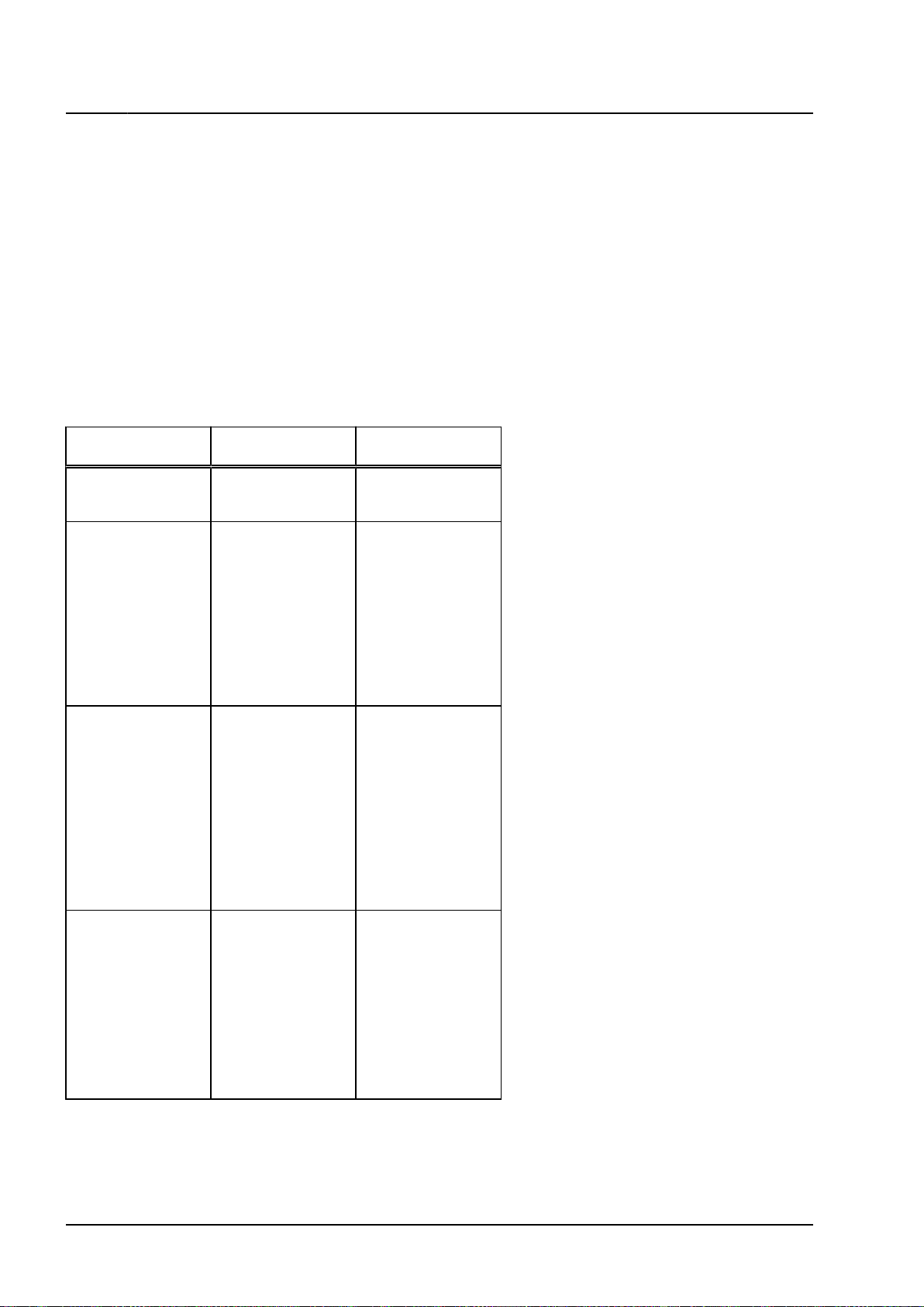
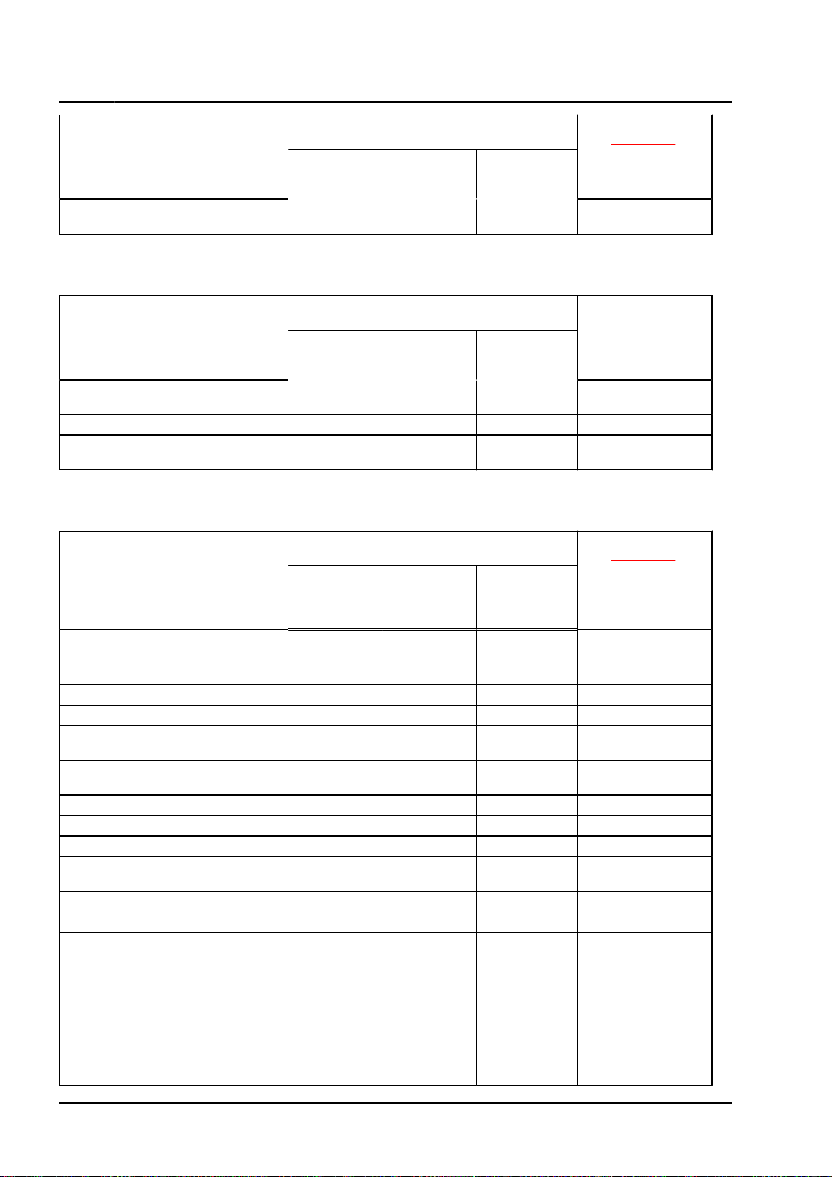
Engine data
Code DCBE
Displace‐
ment
Power kW at rpm 250/5300
Torque Nm at rpm 450/1500 to 5300
Bore Diameter, mm 84.5
Stroke mm 89.0
Compression ratio 11.2
RON min.
Ignition and injection sys‐
tems
Exhaust
emissions
fulfil
Firing order 1-4-3-6-2-5
Exhaust gas recirculation No
Charging Turbocharger
Knock control Yes
Lambda regulation Yes
Charge air cooling Yes
Camshaft timing adjustment Yes
Variable intake manifold No
Secondary air system No
Valves per cylinder 4
l 2.99
98
FSI direct injection
EU 6
1)
2. Identification 5
Touareg 2018 ➤
6-cyl. direct injection (3.0 l, 4V, EA 839, turbocharger) - Edition 11.2020
1)
92 RON also permitted
but with reduced power
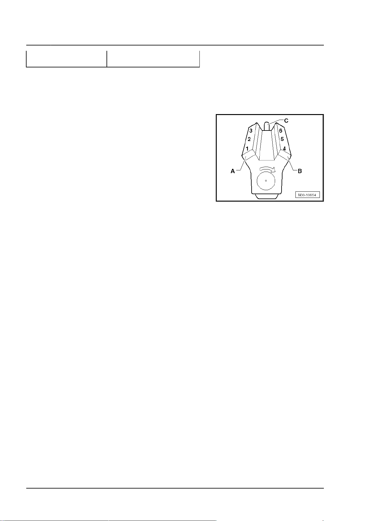
2.2 Numbering of cylinders
Cylinders are numbered beginning with the right side -A- (cylin‐
der bank 1) from the driver's perspective, not from the power
output end -C-. The cylinders are counted on each side in suc‐
cession. -B- = cylinder bank 2.
6 Rep. gr.00 - Technical data

6-cyl. direct injection (3.0 l, 4V, EA 839, turbocharger) - Edition 11.2020
3 Repair instructions
⇒ f3.1 or cleanliness”, page 7
⇒ o3.2 bjects in engine”, page 7
⇒ c3.3 orrosion”, page 7
⇒ a3.4 nd attachment of lines”, page 8
⇒ r3.5 adiator and condensers”, page 8
⇒ f3.6 uel system for leaks”, page 8
3.1 Rules for cleanliness
Even slight soiling can cause faults. For this reason, observe
the following rules for cleanliness when working on the fuel
supply system, the charge air system and the injection system:
♦ Carefully clean connection points and the surrounding area
with engine cleaner or brake cleaner and dry thoroughly
before opening.
♦ Seal open pipes and connections immediately with clean
plugs for example from the engine bung set -VAS 6122-.
♦ Place removed parts on a clean surface. Cover with lint-free
cloths only.
♦ If repair work cannot be performed immediately, carefully
cover or seal components.
♦ Install clean components only. Do not remove replacement
parts from packing until immediately before installing. Do not
use parts that have been stored outside their packaging (e.g.
in tool boxes).
♦ When the system is open, do not work with compressed air
or move the vehicle.
♦ Make sure that no fuel gets onto the fuel hoses. Should this
occur, the fuel hoses must be cleaned immediately.
♦ Protect disconnected electrical connectors from dirt and wa‐
ter, and reconnect them only when dry.
Touareg 2018 ➤
3.2 Foreign objects in engine
♦ To prevent the ingress of foreign bodies during work on
the engine, seal open channels of the intake and exhaust
sections with suitable bungs, for example from the engine
bung set -VAS 6122-.
♦ To prevent subsequent damage when a cylinder bank is
damaged mechanically, check the intake and exhaust sec‐
tions as well as the combustion chambers of the opposite
cylinder bank for foreign bodies.
♦ In the event of mechanical damage on turbocharger refer to
⇒ page 435 .
3.3 Contact corrosion
Contact corrosion can occur if unsuitable connecting elements
(screws, bolts, nuts, washers, etc.) are used.
For this reason, only connecting elements with a special surface
coating have been fitted.
In addition, rubber, plastic and adhesives are made of non-con‐
ductive materials.
3. Repair instructions 7

Touareg 2018 ➤
6-cyl. direct injection (3.0 l, 4V, EA 839, turbocharger) - Edition 11.2020
If there is any doubt about the suitability of parts, a general rule
is to use new parts ⇒ Electronic parts catalogue.
Observe the following:
♦ Use only genuine parts which are tested and compatible with
aluminium.
♦ Damage resulting from contact corrosion is not covered by
the warranty.
3.4 Routing and attachment of lines
♦ To prevent interchanging and to maintain the original instal‐
lation position, mark the fuel, hydraulic system, vacuum and
ACF system pipes or any wiring for example prior to remov‐
al. Make sketches or take photographs if necessary.
♦ To avoid damaging pipes and wires, ensure adequate clear‐
ance from all moving or hot components in the engine com‐
partment on account of the confined space.
3.5 Fitting radiator and condensers
Even if installed correctly, the radiator, the condenser and the
charge air cooler may have small dents in their fins. This does
not mean that these components have been damaged. It is
not permissible to renew radiators, condensers or charge air
coolers only because of such minor dents.
3.6 Checking fuel system for leaks
– Allow engine to run at average revs for a few minutes.
– Switch off ignition.
– Check entire fuel system for leaks.
– If leaks are found although the connections have been tight‐
ened to the correct torque, the relevant component must be
renewed.
– Then test drive the vehicle, accelerating to full throttle at
least once.
– Then, check the high-pressure system for leaks again.
8 Rep. gr.00 - Technical data
6-cyl. direct injection (3.0 l, 4V, EA 839, turbocharger) - Edition 11.2020
4 Hazard classification of high-voltage
system
DANGER
The vehicle’s high-voltage system and the high-voltage bat‐
tery are dangerous and can cause burns or other injuries and
even lead to a fatal electric shock.
– Any work on the high-voltage system, or on systems which
could be indirectly affected by it, may only be carried out
by properly trained and qualified expert personnel.
– In the event of queries or uncertainties regarding the terms
"high-voltage technician" or "high-voltage expert", or those
concerning the high-voltage system, the responsible im‐
porter must be contacted prior to the commencement of
any work.
– Any repair work must be performed in accordance with ap‐
plicable laws and regulations, the recognised engineering
practices, any relevant accident prevention regulations (in
Germany, including but not limited to the Information of
the German Social Accident Insurance (DGUV) 200-005 –
Qualification training for work on vehicles with high-voltage
systems), as well as this workshop manual.
Touareg 2018 ➤
Before work on the high-voltage system is started, a high-volt‐
age technician must de-energise the high-voltage system ⇒
h8 igh-voltage system”, page 689 .
The types of work for which the high-voltage system has to
be de-energised are indicated in the list entitled “Work on the
high-voltage system” ⇒ page 11 .
Work for which the high-voltage system has to be de-energised:
♦ Only the HVT is authorised to certify that the high-voltage
system has been de-energised.
♦ All work on an e-Golf must be carried out only by those who
are at least qualified as electrically instructed persons (EIP).
♦ Regardless of the work to be performed, visually inspect
high-voltage components in the work area.
♦ High-voltage cables must not be overly bent or kinked.
♦ In the event of conspicuous findings or uncertainties, the
high-voltage technician (HVT) or the high-voltage expert
(HVE) must be consulted.
♦ Any work involving metal-removing, deforming and sharp-
edged tools or heat sources such as welding, soldering, hot
air, thermal bonding and infrared drying in the vicinity of
high-voltage components and cables is prohibited. In this
case the high-voltage system must be de-energised and the
respective component removed or sufficiently protected.
♦ All listed work refers to the removal and installation or the
renewal of the individual components.
♦ For regular maintenance work, the high-voltage system does
not have to be de-energised.
For reasons of safety, the following activities must not be car‐
ried out during charging.
♦ Activities that prolong the charging process.
♦ Activities for which the vehicle must be de-energised and
made safe in accordance with the ensuing hazard rating.
4. Hazard classification of high-voltage system 9
Touareg 2018 ➤
6-cyl. direct injection (3.0 l, 4V, EA 839, turbocharger) - Edition 11.2020
♦ Activities during which the vehicle is moved and cables and
connectors could be placed under strain (pulled).
♦ Activities during which the connected charging cable could
present a danger of tripping and injury.
♦ Activities during which the charging cable could block work
paths and emergency exit routes.
♦ Activities on the 12V battery.
The following activities may be carried out with the vehicle diag‐
nostic tester during charging.
♦ Interrogation of event memory and measured values permit‐
ted
♦ The vehicle and control units may be identified.
Explanation of qualifications
Qualification Volks‐
wagen
EIP (person with
electrical training)
HVT (high-voltage
technician)
HVE level 1 (highvoltage expert)
DGUV-I 200-005 Scenario
Chapter 2 Induction training
for non-electrical
work (< 60 VDC)
Chapter 3.1 b Working on inher‐
ently safe HV pro‐
duction vehicles
♦ Vehicles are de-
energised exclu‐
sively with certif‐
ication.
♦ Complete con‐
tact protection in
place.
Chapter 3.2 b Working on not in‐
herently safe HV
production vehicles
♦ Vehicles are al‐
so de-energised
without certifica‐
tion or there is
no complete
contact protec‐
tion in place,
e.g. in the event
of an accident.
HVE level 2 (highvoltage expert)
Chapter 3.3 Working on live ac‐
10 Rep. gr.00 - Technical data
cumulators
♦ Working on
parts supplied
with voltage, in‐
evitably with no
contact protec‐
tion, for fault
finding, compo‐
nent replace‐
ment, etc.
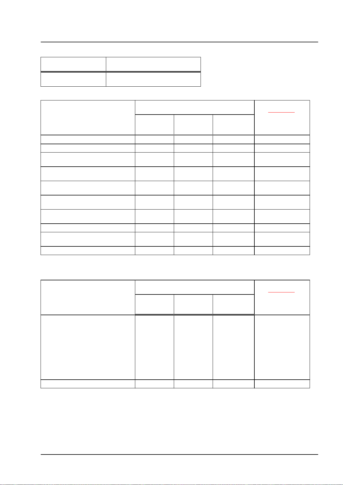
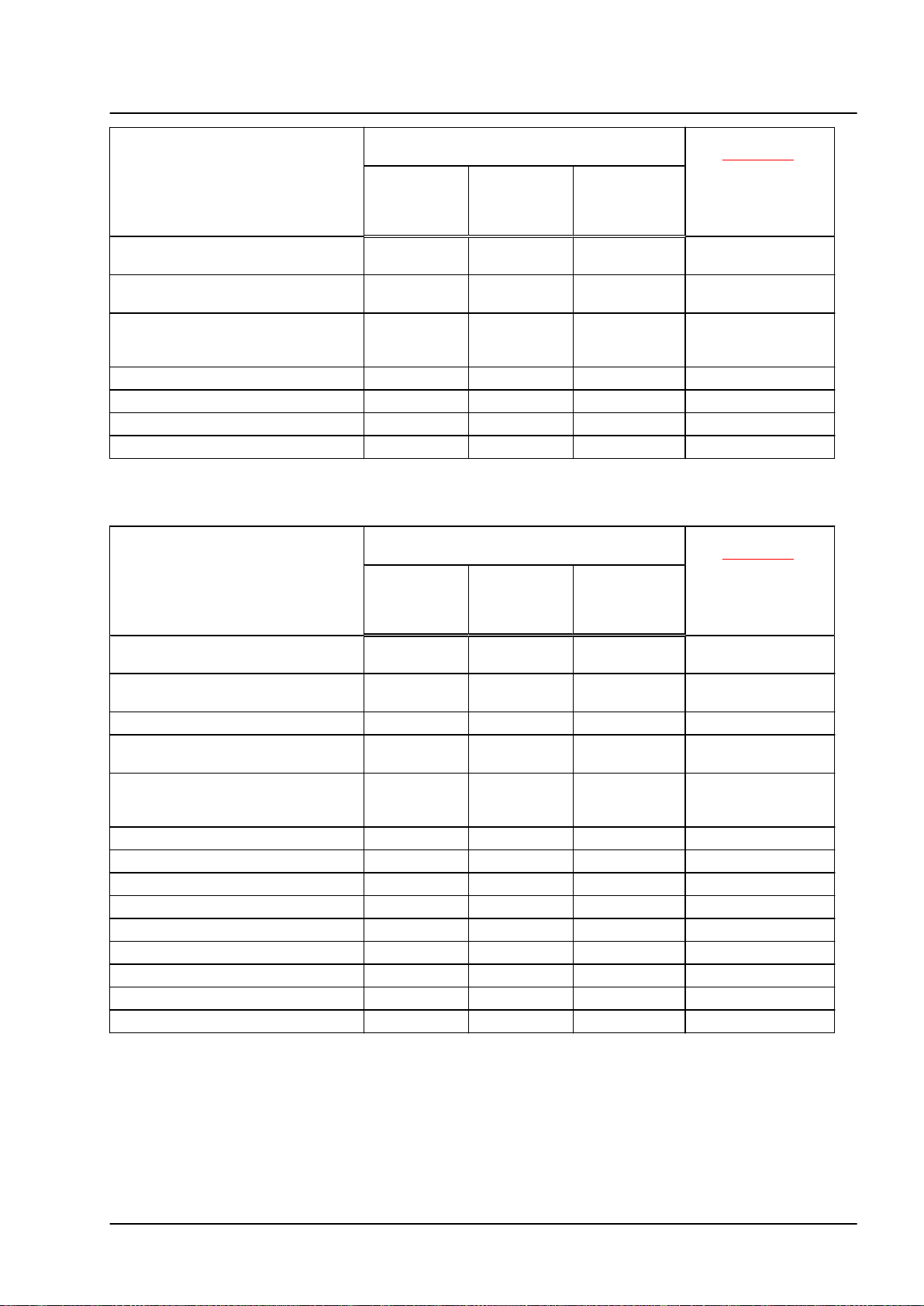
Work on high-voltage system
Touareg 2018 ➤
6-cyl. direct injection (3.0 l, 4V, EA 839, turbocharger) - Edition 11.2020
When working on the
Minimum qualification
following components:
De-energise high-volt‐
age system
Work on power unit
When working on the following
components:
three-phase current drive -VX54-
Electric drive motor -V141Mechatronic unit for dual clutch
gearbox -J743Drive motor temperature sender/ro‐
tor position sender -G712-/-G713Lambda probe 1 ahead of catalytic
converter -GX10Lambda probe 1 after catalytic con‐
verter -GX7Coolant pumps -V467-, -V468-, -
V508-, -V590Valves in coolant circuit
Oil level and oil temperature sender
-G266Combustion engine
HVT
Must the HVT de-energise high-voltage sys‐
tem before work is started?
yes (manual
de-energisa‐
tion)
yes (only di‐
agnostic de-
energisation)
X
X
X
X
X
no
X EIP
X EIP
X EIP
X EIP
X EIP
Minimum qualifica‐
tion: ⇒ page 10
EIP
EIP
EIP
EIP
EIP
Work on power and control electronics for electric drive
When working on the following
components:
Must the HVT de-energise high-voltage sys‐
tem before work is started?
Yes (manual
power discon‐
nect)
Power and control electronics for
electric drive -JX1- with
♦ Electric drive control unit -J841-
♦ Intermediate circuit capacitor 1
-C25-
♦ Voltage converter -A19-
♦ DC/AC converter for drive motor
-A37-
High-voltage system fuse 3 -S353-
yes (only di‐
agnostic de-
energisation)
X
X
no
Minimum qualifica‐
tion: ⇒ page 10
EIP
EIP
4. Hazard classification of high-voltage system 11
Touareg 2018 ➤
6-cyl. direct injection (3.0 l, 4V, EA 839, turbocharger) - Edition 11.2020
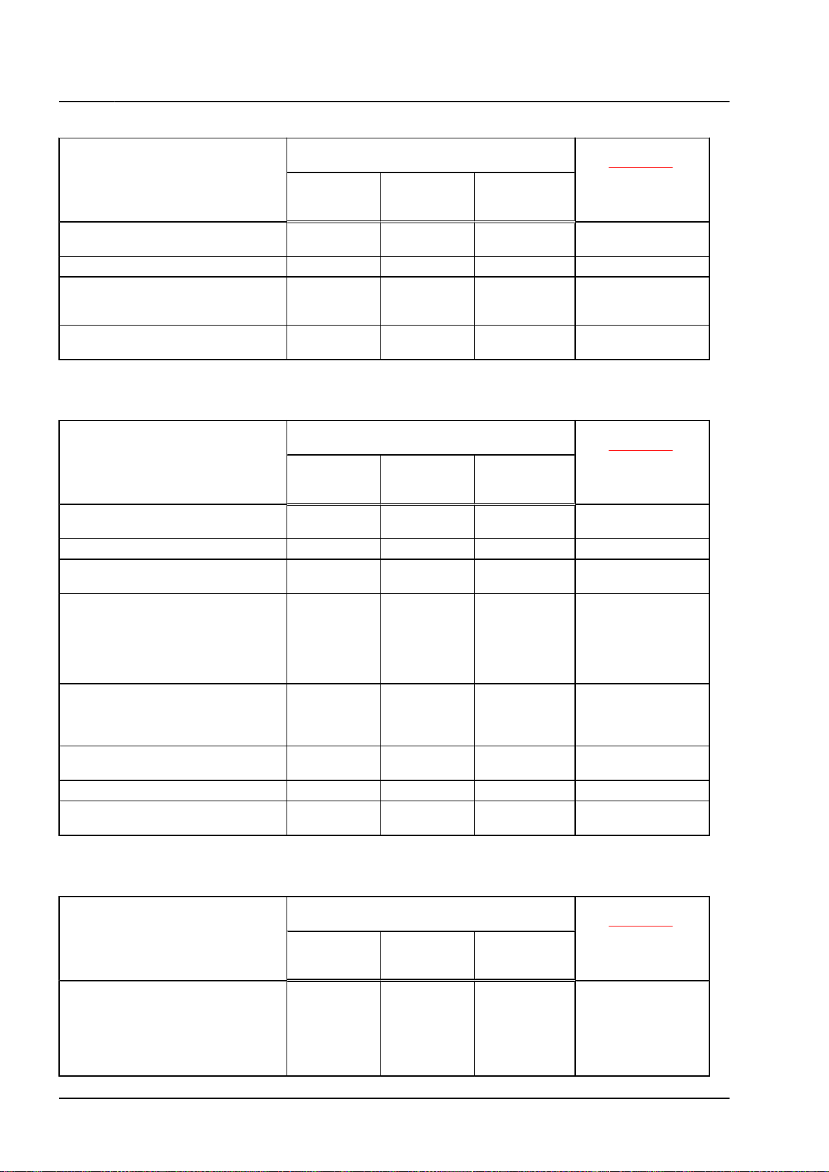
Work on high-voltage system
When working on the following
components:
Potential equalisation lines (earth)
with connection to HV components
Measure insulation resistance
Maintenance connector for high-
voltage system (service connector,
service disconnector)
PX – high-voltage cables (orange)
in vehicle
Work on heating and air conditioning system
When working on the following
components:
Electrical air conditioner compres‐
sor -V470-
High-voltage heater (PTC) -Z115Work on heating and air condition‐
ing system in vehicle interior
Refrigerant lines in vehicle periph‐
ery. Work which is not directly on
the AC compressor and can be car‐
ried out without opening the refrig‐
erant circuit, e.g. loosening and se‐
curing refrigerant lines.
Air conditioning performance test.
For checking the pressure levels in
the refrigerant circuit by means of
air conditioning service equipment.
Refrigerant lines directly on the AC
compressor
Extract, evacuate or fill refrigerant
Heat exchanger for high-voltage
battery -VX63-
Must the HVT de-energise high-voltage sys‐
tem before work is started?
Yes (manual
power discon‐
nect)
Must the HVT de-energise high-voltage sys‐
tem before work is started?
Yes (manual
power discon‐
nect)
yes (only di‐
agnostic de-
energisation)
yes (only di‐
agnostic de-
energisation)
Minimum qualifica‐
tion: ⇒ page 10
no
X
X
X
X
X
X
X EIP
Minimum qualifica‐
tion: ⇒ page 10
no
X EIP
X EIP
X EIP
X EIP
X EIP
HVT
HVT
HVT
EIP
EIP
EIP
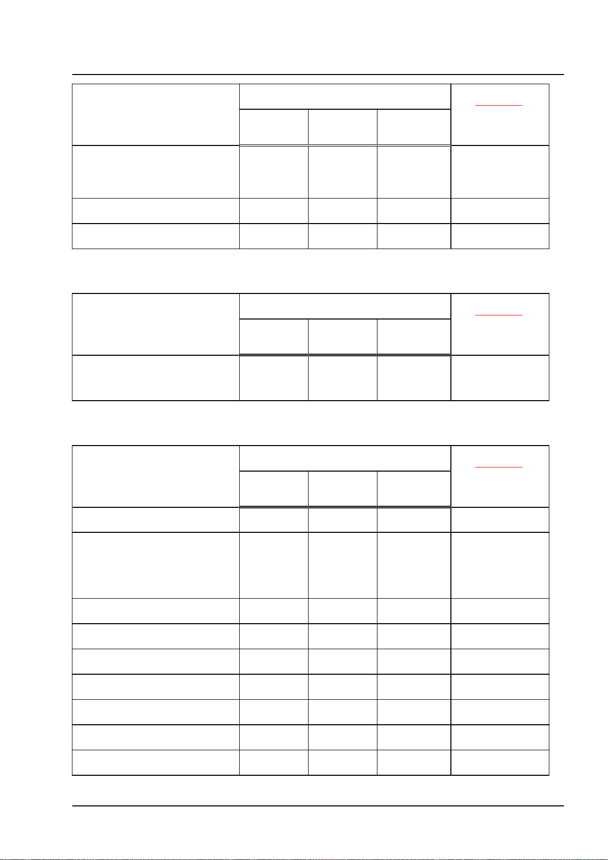
Work on charging connection
When working on the following
components:
High-voltage battery charging sock‐
et 1 -UX4- with
♦ Temperature sender for charg‐
ing socket 1 -G853-
♦ Actuator for locking
12 Rep. gr.00 - Technical data
Must the HVT de-energise high-voltage sys‐
tem before work is started?
Yes (manual
power discon‐
nect)
yes (only di‐
agnostic de-
energisation)
X
no
Minimum qualifica‐
tion: ⇒ page 10
EIP
Touareg 2018 ➤
6-cyl. direct injection (3.0 l, 4V, EA 839, turbocharger) - Edition 11.2020
When working on the following
components:
Module for battery charge selector
buttons -EX32♦ LED module for charging socket
1 -L263-
Manual release mechanism for
charging connector
Charge high-voltage battery in
workshop area
Work on charging unit
When working on the following
components:
Charging unit 1 for high-voltage
battery -AX4With control unit for high-voltage
battery charging unit -J1050-
Must the HVT de-energise high-voltage sys‐
tem before work is started?
Yes (manual
power discon‐
nect)
yes (only di‐
agnostic de-
energisation)
X
no
X
X EIP
Must the HVT de-energise high-voltage sys‐
tem before work is started?
Yes (manual
power discon‐
nect)
yes (only di‐
agnostic de-
energisation)
X
no
Minimum qualifica‐
tion: ⇒ page 10
EIP
EIP
Minimum qualifica‐
tion: ⇒ page 10
EIP
Work on high-voltage battery
When working on the following
components:
Removing and installing underbody
cladding
Removing and installing high-volt‐
age battery 1 -AX2-, de-energised,
high voltage system connection and
DC charging connection disconnec‐
ted. Approval by technician quali‐
fied at least as HVT.
Disconnect high voltage system
connection
Disconnect low-voltage connection
of high-voltage battery
Battery regulation control unit J840-
Switching unit for high-voltage bat‐
tery -SX6- (battery removed)
Module monitor control unit for bat‐
teries -J497- (battery removed)
Open high-voltage battery 1 -AX2(battery removed)
Bond/screw high-voltage battery 1
-AX2- (battery removed)
Must the HVT de-energise high-voltage sys‐
tem before work is started?
Yes (manual
power discon‐
nect)
yes (only di‐
agnostic de-
energisation)
X
X
no
X
X EIP
X EIP
Minimum qualifica‐
tion: ⇒ page 10
EIP
EIP
HVT
HVE
HVE
HVE
HVE
4. Hazard classification of high-voltage system 13
Touareg 2018 ➤
6-cyl. direct injection (3.0 l, 4V, EA 839, turbocharger) - Edition 11.2020
When working on the following
components:
Battery module 1 -J991- and other
battery modules (battery removed)
Work on accident vehicles
When working on the following
components:
Status assessment / initial assess‐
ment of risk status
Body work (with straightening jig)
Paint vehicle – observe instructions
in paint manual
Work in vicinity of high-voltage components
Must the HVT de-energise high-voltage sys‐
tem before work is started?
Yes (manual
power discon‐
Must the HVT de-energise high-voltage sys‐
tem before work is started?
Yes (manual
power discon‐
yes (only di‐
agnostic de-
nect)
nect)
energisation)
yes (only di‐
agnostic de-
energisation)
X
Minimum qualifica‐
tion: ⇒ page 10
no
HVE
Minimum qualifica‐
tion: ⇒ page 10
no
HVT
X EIP
EIP
When working on the following
components or for following work:
Body work (assembly work as well
as glass and dent repairs)
Gearbox with electric drive motor
Steering rack
Subframe, front
Exhaust system, in front area of ve‐
hicle
Exhaust system, in rear area of ve‐
hicle
Front brakes
Rear brakes
Brake servo
Brake pressure accumulator for en‐
ergy recovery
Rear axle and running gear
Underbody cladding
When welding, cover high-voltage
components and visually inspect af‐
terwards
Work involving metal-removing, de‐
forming and sharp-edged tools or
heat sources such as welding, sol‐
dering, hot air, thermal bonding
and infrared drying in the vicinity
of high-voltage components and ca‐
bles
Must the HVT de-energise high-voltage sys‐
tem before work is started?
yes (diagnos‐
tic and man‐
ual power dis‐
connection)
Yes (only di‐
agnostic pow‐
er disconnec‐
tion)
X
X
X
no
X
X EIP
X EIP
X EIP
X EIP
X EIP
X EIP
X EIP
X EIP
X EIP
X EIP
Minimum qualifica‐
tion: ⇒ page 10
EIP
EIP
EIP
EIP
14 Rep. gr.00 - Technical data
Touareg 2018 ➤
6-cyl. direct injection (3.0 l, 4V, EA 839, turbocharger) - Edition 11.2020
When working on the following
components or for following work:
Work for which the engine is lifted,
on right side (e.g. engine mounting)
Work for which the engine is lifted,
on left side (e.g. gearbox mounting)
Control units and electric compo‐
nents of 12-V system (excluding
airbag)
Battery -AFront left headlight -MX1Front right headlight -MX2Change bulb in headlight
General work
When working on the following
components:
Drain and fill fluids (coolant and
oils)
Coolant circuit and coolant expan‐
sion tank
Change tyres
Miscellaneous work on 12 V system
(excluding airbag)
Work on earth points of 12 V sys‐
tem (without potential equalisation
lines)
Tail lights
Renew/repair windows
Repairs in vehicle interior
Repairs in roof area
Repairs on rear lid
Repairs on bumpers
Move lock carrier to service position
Removing and installing lock carrier
Repair work on lock carrier
Must the HVT de-energise high-voltage sys‐
tem before work is started?
yes (diagnos‐
tic and man‐
ual power dis‐
connection)
Yes (only di‐
agnostic pow‐
er disconnec‐
tion)
no
X
X EIP
X EIP
X EIP
X EIP
X EIP
X EIP
De-energise high-voltage system before work
is started?
yes (diagnos‐
tic and man‐
ual power dis‐
connection)
Yes (only di‐
agnostic pow‐
er disconnec‐
tion)
no
X
X EIP
X EIP
X EIP
X EIP
X EIP
X EIP
X EIP
X EIP
X EIP
X EIP
X EIP
X EIP
X EIP
Minimum qualifica‐
tion: ⇒ page 10
EIP
Minimum qualifica‐
tion: ⇒ page 10
EIP
4. Hazard classification of high-voltage system 15
Touareg 2018 ➤
6-cyl. direct injection (3.0 l, 4V, EA 839, turbocharger) - Edition 11.2020
10 – Removing and installing engine
1 Removing and installing engine
⇒ e1.1 ngine”, page 16
⇒ e1.2 ngine and gearbox”, page 49
⇒ e1.3 ngine from scissor-type assembly platform”, page 57
⇒ e1.4 ngine on engine and gearbox support”, page 58
⇒ e1.5 ngine”, page 61
1.1 Removing engine
⇒ e1.1.1 ngine – vehicles without high-voltage system”, page
16
⇒ e1.1.2 ngine – vehicles with high-voltage system”, page 30
1.1.1 Removing engine – vehicles without high-voltage system
Special tools and workshop equipment required
♦ Hook -10-222A/20-
♦ Engine bung set -VAS 6122-
16 Rep. gr.10 - Removing and installing engine
6-cyl. direct injection (3.0 l, 4V, EA 839, turbocharger) - Edition 11.2020
♦ Scissor-type assembly platform -VAS 6131 B-
♦ Set of mountings for Audi -VAS 6131/10-
Touareg 2018 ➤
♦ Supplement set, Audi A8 >2002 -VAS 6131/11-, not shown
♦ Supplement set, Audi Q7 > 2005 -VAS 6131/13-
♦ Coolant collection system -VAS 5014- or drip tray for work‐
shop hoists -VAS 6208-
1. Removing and installing engine 17
Touareg 2018 ➤
6-cyl. direct injection (3.0 l, 4V, EA 839, turbocharger) - Edition 11.2020
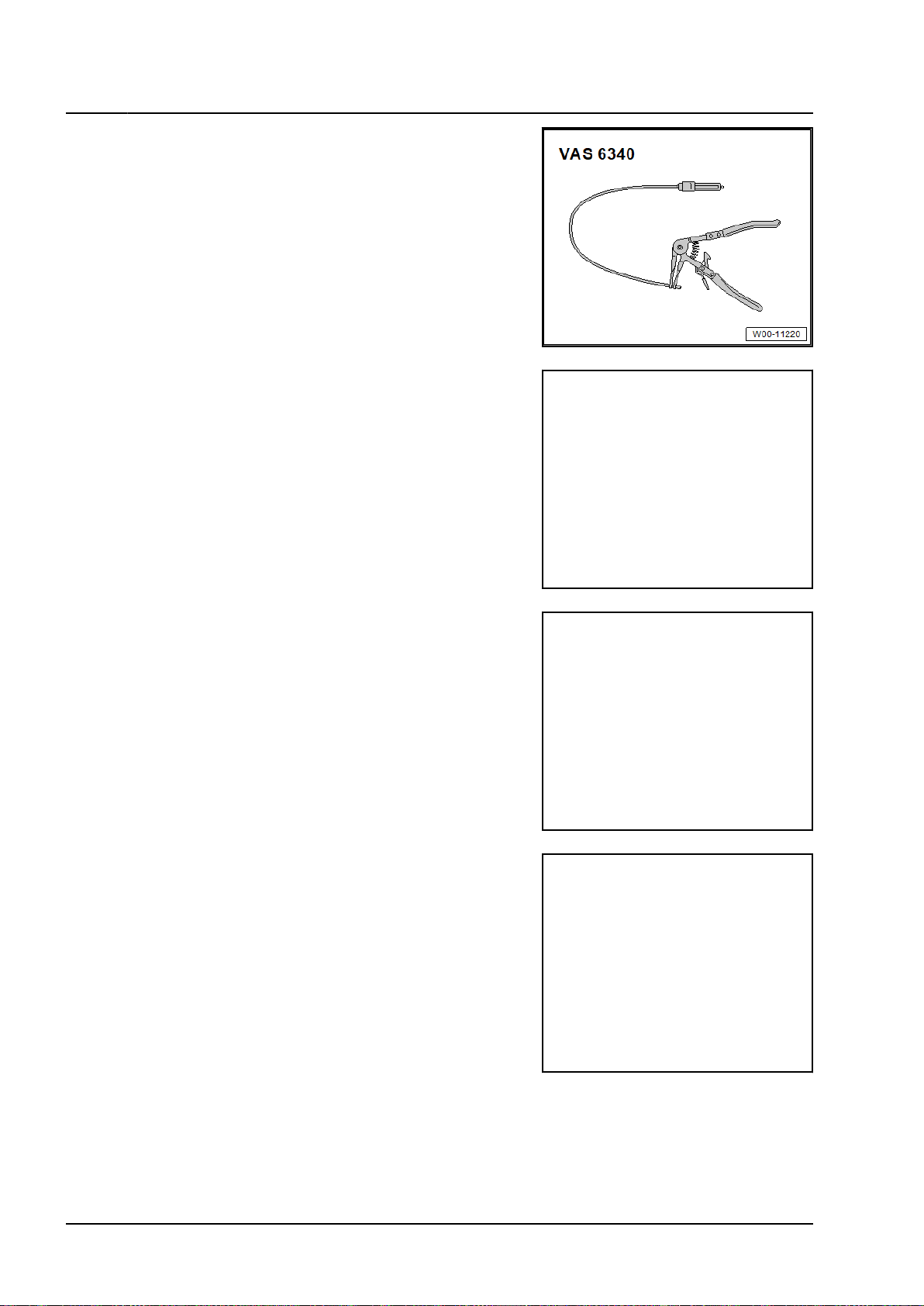
♦ Hose clamp pliers -VAS 6340-
♦ Spring-type clip pliers -VAS 6362-
♦ Engine and gearbox jack -VAS 6931-
♦ Ball joint splitter -VAS 251 805-
18 Rep. gr.10 - Removing and installing engine
6-cyl. direct injection (3.0 l, 4V, EA 839, turbocharger) - Edition 11.2020
♦ Tensioning strap -T10038-
♦ Stepladder, commercially available
♦ Safety goggles
♦ Safety gloves
Procedure
♦ The engine is removed from underneath together with the
gearbox and subframe (with lock carrier installed).
♦ Fit cable tie in same place when installing.
♦ Observe rules for cleanliness ⇒ f3.1 or cleanliness”, page 7 .
♦ All bolts on running gear components with bonded rubber
bushes may be tightened only when the component is in the
unladen position (normal position).
♦ Bonded rubber bushes can be twisted only to a limited
extent. Axle components with bonded rubber bushes must
therefore be brought to a position equivalent to the unla‐
den (normal) position before being tightened. Otherwise, the
bonded rubber bush would be subject to torsion loading,
shortening its service life.
– Before starting work, determine unladen position ⇒ Running
gear, axles, steering; Rep. gr. 00; Repair instructions; Rais‐
ing vehicles with coil springs, wheel bearing in unladen posi‐
tion.
• To be able to turn the propshaft during removal, the electro‐
mechanical parking brake must be released before discon‐
necting the battery.
– Move front wheels to straight-ahead position.
– Switch off ignition.
– Disconnect earth wire from battery terminal ⇒ Electrical sys‐
tem; Rep. gr. 27; Battery, Disconnecting and connecting bat‐
tery.
Touareg 2018 ➤
– Remove air filter housing ⇒ a4.2 nd installing air filter hous‐
ing”, page 495 .
– Remove lock carrier cover ⇒ General body repairs, exterior;
Rep. gr. 63; Body - front; Removing and installing attach‐
ments.
– Remove front wheels ⇒ Running gear, axles, steering; Rep.
gr. 44; Wheels, tyres.
– Remove front wheel housing liner on left and right as well as
wheel spoiler ⇒ General body repairs, exterior; Rep. gr. 66;
Wheel housing liner; Assembly overview - front wheel hous‐
ing liner.
1. Removing and installing engine 19
Touareg 2018 ➤
6-cyl. direct injection (3.0 l, 4V, EA 839, turbocharger) - Edition 11.2020
– Remove noise insulation ⇒ General body repairs, exterior;
Rep. gr. 66; Noise insulation; Removing and installing noise
insulation.
– Remove front lower longitudinal member ⇒ General body
repairs, exterior; Rep. gr. 50; Lock carrier; Removing and
installing lower longitudinal member.
– Remove cross strut for subframe ⇒ Running gear, axles,
steering; Rep. gr. 40; Subframe; Removing and installing
cross struts for subframe.
– Remove propshaft ⇒ Propshaft and rear final drive; Rep.
gr. 39; Propshaft; Removing and installing propshaft.
– Unscrew bolts -arrows- on left and right, and detach upper
part -1- of subframe shield.
– Remove front silencers on left and right ⇒ a1.2 nd installing
front silencer”, page 540 .
– Drain coolant ⇒ a1.5 nd adding coolant”, page 323 .
– Release hose clips -1 and 3-, remove air hose from air pipe.
– Disconnect fuel hose -2- ⇒ Fuel supply; Rep. gr. 20; Plug-in
connectors; Disconnecting plug-in connectors.
20 Rep. gr.10 - Removing and installing engine
6-cyl. direct injection (3.0 l, 4V, EA 839, turbocharger) - Edition 11.2020
– Release hose clip -1- and disconnect hose for activated
charcoal filter system.
– Seal open pipes and connections with thoroughly cleaned
plugs from engine bung set -VAS 6122-.
– Release hose clip -1-, pull off air pipe, push towards left and
tie in place.
Touareg 2018 ➤
– Release fastener -arrow- and open electronics box -1-.
– Unscrew nut -2- and expose B+ wire.
– Free off electric wire -1- from wiring duct.
1. Removing and installing engine 21
Touareg 2018 ➤
6-cyl. direct injection (3.0 l, 4V, EA 839, turbocharger) - Edition 11.2020
– Unscrew nut -2- and free off earth wire.
– Remove bolt -3- and nut -4- and free off wiring duct.
– Lift retaining clip -1- and disconnect coolant hose.
– Equipment version without auxiliary heater: release fastener
-arrow- and push coolant circulation pump -V50- to one side.
– Release hose clip -1- and detach coolant hose.
– Lift retaining clip -2-, remove upper left coolant hose from
radiator.
– Release fastener -arrow-, detach vacuum hose -1-, ensuring
when doing so that it is not damaged.
22 Rep. gr.10 - Removing and installing engine

6-cyl. direct injection (3.0 l, 4V, EA 839, turbocharger) - Edition 11.2020
– Separate electrical connectors -1- on engine control unit
-J623- and free off.
Touareg 2018 ➤
– Take electrical connector -2- out of bracket, unplug it and
move electrical wiring clear.
– Remove connector -3- from retainer, disconnect it and lay
wire to one side.
– Loosen nut -arrow- a few turns, free off electrical connector
-2- and separate.
– Unscrew nut -1- and free off earth wires.
– Unscrew nut -arrow- and free off earth wires.
1. Removing and installing engine 23

Touareg 2018 ➤
6-cyl. direct injection (3.0 l, 4V, EA 839, turbocharger) - Edition 11.2020
– Separate electrical connectors for electrohydraulic engine
mounting solenoid valves on left and right -arrow-, free off
electrical wires.
– Separate left and right electrical connector -2- for front
speed sensor -G45-/-G47- and free off electrical wire.
– If fitted, separate left and right electrical connector -arrow-
for front vehicle level sender -G78-/-G289- and free off elec‐
trical wire.
24 Rep. gr.10 - Removing and installing engine

6-cyl. direct injection (3.0 l, 4V, EA 839, turbocharger) - Edition 11.2020
– Remove brake caliper and, with brake hose still connected,
suspend it in wheel housing using wire ⇒ Brake system;
Rep. gr. 46; Front brake; Removing and installing brake cali‐
per.
– Loosen threaded connection -1-.
Touareg 2018 ➤
NOTICE
Danger of damage to wheel bearing housing from deforma‐
tion.
– Do not widen slots in wheel bearing housing.
– Pull out joint pins of upper suspension link -2- from wheel
bearing housing.
– Repeat work sequence on opposite side of vehicle.
– Unscrew nut -4- on both sides. (Bolt -3- is removed at later
stage.)
1. Removing and installing engine 25

Touareg 2018 ➤
6-cyl. direct injection (3.0 l, 4V, EA 839, turbocharger) - Edition 11.2020
Note
♦
Bolt -3- will be removed later.
♦
-Items 1 and 2- can be disregarded.
– Remove anti-roll bar ⇒ Running gear, axles, steering; Rep.
gr. 40; Subframe; Removing and installing anti-roll bar.
– Remove cross strut for subframe ⇒ Running gear, axles,
steering; Rep. gr. 40; Subframe; Removing and installing
cross struts for subframe.
– Remove intermediate steering shaft from steering rack
and push together ⇒ Running gear, axles, steering; Rep.
gr. 48; Steering column; Removing and installing intermedi‐
ate steering shaft.
NOTICE
Risk of irreparable damage to poly V-belt that has already
been used by reversing direction of rotation.
– Mark direction of rotation before removing.
– Observe direction of rotation when re-installing.
– Loosen poly V-belt by swivelling tensioning device clockwise
-arrow- using socket Torx T 60 -T40087-.
– Remove poly V-belt and lock tensioning device using locking
pin -T40098-.
– Disconnect electrical connector -1-.
26 Rep. gr.10 - Removing and installing engine

6-cyl. direct injection (3.0 l, 4V, EA 839, turbocharger) - Edition 11.2020
NOTICE
Danger of damage to refrigerant lines and refrigerant hoses
as air conditioner compressor is removed and swivelled.
– Do NOT stretch, kink or bend refrigerant lines and hoses.
– Unscrew bolts -arrows-, remove air conditioner compressor
from bracket and raise and tie on left-hand side.
– Separate connector -2- for gearbox oil cooling valve -N509-.
Touareg 2018 ➤
NOTICE
Risk of irreparable damage from electrostatic discharge.
– Do not touch contacts with bare hands.
– Touch earth (e.g. lifting platform) to discharge any static
electricity.
– Turn retainer catch anti-clockwise -arrow- and unplug electri‐
cal connector -1- at gearbox.
1. Removing and installing engine 27

Touareg 2018 ➤
6-cyl. direct injection (3.0 l, 4V, EA 839, turbocharger) - Edition 11.2020
– Remove front left underbody cladding ⇒ General body re‐
pairs, exterior; Rep. gr. 66; Underbody cladding; Removing
and installing underbody cladding.
– Unscrew bolts -arrows-, free off emergency release cable -1-
for parking lock.
Set up the scissor-type assembly platform as follows:
– Arrange scissor-type assembly platform -VAS 6131 B-
with support set for Audi -VAS 6131/10-, adapter -VAS
6131/11-1- and adapter -VAS 6131/13-2- as follows:
Platform
coordinates
C4 /10-1 /10-4 /10-5 /10-12
E4 /10-1 /10-4 /10-5 /10-11
E10 /10-1 /10-2 /10-5 /13-2
B15 /10-1 /10-2 /10-5 /11-6
F15 /10-1 /10-2 /10-5 /11-6
– First, bolt mounting elements to scissor-type mounting plat‐
form and tighten bolts by hand.
– Place scissor-type assembly platform -VAS 6131 B- in a
horizontal position.
• Take note of spirit level (bubble gauge).
– Move scissor-type assembly platform -VAS 6131 B- under
engine/gearbox assembly.
Parts from -VAS 6131/10-, adapter -VAS
6131/11-1- and adapter -VAS 6131/13-2-
28 Rep. gr.10 - Removing and installing engine

6-cyl. direct injection (3.0 l, 4V, EA 839, turbocharger) - Edition 11.2020
– Mount support elements from -VAS 6131/10- on left and
right of engine.
– Make sure that threaded spindles are screwed in completely.
– Support subframe with support elements from -
VAS 6131/10- and adapter -VAS 6131/13-2-.
Touareg 2018 ➤
Note
The support elements only support the subframe, the base
plate is not bolted to the scissor-type assembly platform.
– Mount support elements from -VAS 6131/10- and adapters
-VAS 6131/11-1- on tunnel cross member.
– Turn remaining spindles for support elements upwards until
all locating lugs make contact with mounting points.
– Bolt base plates for support elements to scissor-type assem‐
bly platform -VAS 6131 B- and tighten bolts to 20 Nm.
1. Removing and installing engine 29

Touareg 2018 ➤
6-cyl. direct injection (3.0 l, 4V, EA 839, turbocharger) - Edition 11.2020
– Fix subframe in position ⇒ Running gear, axles, steering;
Rep. gr. 40; Subframe; Fixing subframe in position.
– Unscrew bolts -arrows- on tunnel cross member.
– Remove bolt -3- on both sides.
Note
Threaded connections -1, 2, 4- already separated.
NOTICE
Danger of damage to lines and hoses as well as engine com‐
partment as engine/gearbox assembly is lowered.
– Check that all connections between engine, gearbox, sub‐
frame and body have been disconnected.
– When lowering, carefully guide engine/gearbox assembly
with assembly carrier out of engine compartment.
– Lower scissor-type assembly platform -VAS 6131 B- with
engine/gearbox assembly and pull out from under vehicle.
1.1.2 Removing engine – vehicles with highvoltage system
Special tools and workshop equipment required
♦ Engine bung set -VAS 6122-
30 Rep. gr.10 - Removing and installing engine

6-cyl. direct injection (3.0 l, 4V, EA 839, turbocharger) - Edition 11.2020
♦ Scissor-type assembly platform -VAS 6131 B-
♦ Set of mountings for Audi -VAS 6131/10-
Touareg 2018 ➤
♦ Two adapters -VAS 6131/13-2- from supplement set, Audi
Q7 >2005 -VAS 6131/13-
♦ Coolant collection system -VAS 5014- or drip tray for work‐
shop hoists -VAS 6208-
♦ Hose clamp pliers -VAS 6340-
1. Removing and installing engine 31

Touareg 2018 ➤
6-cyl. direct injection (3.0 l, 4V, EA 839, turbocharger) - Edition 11.2020
♦ Spring-type clip pliers -VAS 6362-
♦ Engine and gearbox jack -VAS 6931-
♦ Ball joint splitter -VAS 251 805-
♦ Ball joint splitter -VAS 251 809- with -VAS 251 809/1-, not
illustrated
♦ Tensioning strap -T10038-
♦ Stepladder, commercially available
♦ Safety goggles
♦ Safety gloves
32 Rep. gr.10 - Removing and installing engine

6-cyl. direct injection (3.0 l, 4V, EA 839, turbocharger) - Edition 11.2020
Procedure
♦ The engine is removed from underneath together with the
gearbox and subframe (with lock carrier installed).
♦ Fit cable tie in same place when installing.
♦ Observe rules for cleanliness ⇒ f3.1 or cleanliness”, page 7 .
♦ All bolts on running gear components with bonded rubber
bushes may be tightened only when the component is in the
unladen position (normal position).
♦ Bonded rubber bushes can be twisted only to a limited
extent. Axle components with bonded rubber bushes must
therefore be brought to a position equivalent to the unla‐
den (normal) position before being tightened. Otherwise, the
bonded rubber bush would be subject to torsion loading,
shortening its service life.
– Before starting work, determine reference position ⇒ Run‐
ning gear, front-wheel drive and all-wheel drive; Rep. gr. 00;
Repair instructions; Raising wheel bearing to normal level on
vehicles with air suspension.
– Move front wheels to straight-ahead position.
– Switch off ignition.
• To be able to turn the propshaft during removal, the electro‐
mechanical parking brake must be released before discon‐
necting the battery.
Touareg 2018 ➤
DANGER
Danger to life due to high voltage.
Severe or fatal injury from electric shock.
– The high-voltage system must be de-energised by a suita‐
bly qualified technician.
– De-energise high-voltage system ⇒ h8 igh-voltage system”,
page 689 .
– Disconnect earth wire from battery terminal ⇒ Electrical sys‐
tem; Rep. gr. 27; Battery, Disconnecting and connecting bat‐
tery.
– Remove air filter housing ⇒ a4.2 nd installing air filter hous‐
ing”, page 495 .
– Remove lock carrier cover ⇒ General body repairs, exterior;
Rep. gr. 63; Body - front; Removing and installing attach‐
ments.
– Remove front wheels ⇒ Running gear, axles, steering; Rep.
gr. 44; Wheels, tyres.
– Remove front wheel housing liner on left and right as well as
wheel spoiler ⇒ General body repairs, exterior; Rep. gr. 66;
Wheel housing liner; Assembly overview - front wheel hous‐
ing liner.
– Remove noise insulation ⇒ General body repairs, exterior;
Rep. gr. 66; Noise insulation; Removing and installing noise
insulation.
– Remove front lower left and front lower right longitudinal
member ⇒ General body repairs, exterior; Rep. gr. 50; Lock
carrier; Removing and installing lower longitudinal member.
– Remove cross strut for subframe ⇒ Running gear, axles,
steering; Rep. gr. 40; Subframe; Removing and installing
cross struts for subframe.
1. Removing and installing engine 33

Touareg 2018 ➤
6-cyl. direct injection (3.0 l, 4V, EA 839, turbocharger) - Edition 11.2020
– Remove propshaft ⇒ Rear final drive; Rep. gr. 39; Propshaft;
Removing and installing propshaft.
– Unscrew bolts -arrows- on left and right, and detach upper
part -1- of subframe shield.
– Remove front silencers on left and right ⇒ a1.2 nd installing
front silencer”, page 540 .
– Drain coolant ⇒ page 323 .
– Place collecting tray of coolant collecting system -VAS 5014-
or drip tray for workshop hoists -VAS 6208- underneath.
CAUTION
Danger of injury; the radiator fan can run at any time.
– When working in vicinity of radiator, maintain safe distance
from fan.
– Lift retaining clip -arrow-, detach lower right coolant hose
from radiator, and drain off remaining coolant.
– Release hose clips -1 and 3-, remove air hose from air pipe.
34 Rep. gr.10 - Removing and installing engine

6-cyl. direct injection (3.0 l, 4V, EA 839, turbocharger) - Edition 11.2020
– Disconnect fuel hose -2- ⇒ Fuel supply; Rep. gr. 20; Plug-in
connectors; Disconnecting plug-in connectors.
– Release hose clip -1- and disconnect hose for activated
charcoal filter system.
– Seal open lines and connections with clean plugs from en‐
gine bung set -VAS 6122-.
– Release and disconnect electrical connector -1- for coolant
shortage indicator sender -G32-.
Touareg 2018 ➤
– Release fasteners -arrow- using a screwdriver, pull coolant
expansion tank -2- with coolant hoses connected as far as
possible upwards out of bracket, and place it aside.
– Unclip refrigerant line -7- and coolant line -2- from retainer,
and move it aside.
1. Removing and installing engine 35

Touareg 2018 ➤
6-cyl. direct injection (3.0 l, 4V, EA 839, turbocharger) - Edition 11.2020
– Open retainer -3-, and move coolant hose -6- aside.
– Unscrew bolts -arrows-.
– Detach bracket of coolant expansion tank -1- upwards, and
lay it aside. While doing so, guide the guide piece out of
grommet -4- of bracket -5-.
– Release hose clip -1-, pull off air pipe, push towards left and
tie in place.
– Release fastener -arrow- and open electronics box -1-.
– Unscrew nut -2-, and move line aside.
– Free off electric wire -1- from wiring duct.
– Unscrew nut -2- and free off earth wire.
36 Rep. gr.10 - Removing and installing engine

6-cyl. direct injection (3.0 l, 4V, EA 839, turbocharger) - Edition 11.2020
– Remove bolt -3- and nut -4- and free off wiring duct.
– Remove particulate filter ⇒ page 551 .
– Unscrew bolts -arrows-, and detach heat shield -1- from
gearbox.
– Clamp off coolant hoses -1 and 2- using hose clamps, up to
25 mm -3094- -3 and 4-, and detach them by loosening hose
clips -arrows A-.
Touareg 2018 ➤
– Unclip coolant hoses -1 and 2- -arrows B-, and tie them up
to left side of vehicle.
– Lift retaining clip -arrow- and disconnect coolant hose.
– Lift retaining clip -1-, and disconnect coolant bleeder line -5-.
1. Removing and installing engine 37

Touareg 2018 ➤
6-cyl. direct injection (3.0 l, 4V, EA 839, turbocharger) - Edition 11.2020
– Lift retaining clip -2-, remove upper left coolant hose from
radiator.
– Clamp off coolant hoses -1 and 2- using hose clamps, up to
25 mm -3094- -3-.
– Loosen hose clips -arrows A-, and pull off/remove coolant
hoses -1, 2 and 5-.
– Open clips -arrow B-, and tie coolant hoses -1 and 2- to one
side.
– Seal ATF cooler connections using engine bung set -VAS
6122-.
– Release, disconnect and move aside electrical connectors
-1- on engine control unit -J623-.
38 Rep. gr.10 - Removing and installing engine

6-cyl. direct injection (3.0 l, 4V, EA 839, turbocharger) - Edition 11.2020
– Remove electrical connector -2- from bracket, disconnect it,
and move electrical wires aside.
– Release fastener -arrow-, detach vacuum hose -1-, ensuring
when doing so that it is not damaged.
Touareg 2018 ➤
– Remove electrical connector -3- from retainer, disconnect it
and free off wire.
– Loosen nut -arrow- a few turns, then free off and disconnect
electrical connector -2-.
– Unscrew nut -1-, and free off earth wires.
– Unscrew nut -arrow-, and free off earth wires.
1. Removing and installing engine 39

Touareg 2018 ➤
6-cyl. direct injection (3.0 l, 4V, EA 839, turbocharger) - Edition 11.2020
– Separate electrical connector -arrow- for electrohydraulic en‐
gine mounting solenoid valve on left and right.
– Move electrical wiring clear.
– Release and disconnect electrical connector -2- for front
speed sensor -G45-/-G47- on left and right.
– Free off electrical wire.
Note
Disregard -item 1-.
– If fitted, release and disconnect electrical connector -arrow-
for front vehicle level sender -G78-/-G289- on left and right.
40 Rep. gr.10 - Removing and installing engine

6-cyl. direct injection (3.0 l, 4V, EA 839, turbocharger) - Edition 11.2020
– Free off electrical wire.
– Remove brake caliper and, with brake hose still connected,
suspend it in wheel housing using wire ⇒ Brake system;
Rep. gr. 46; Front brake; Removing and installing brake cali‐
per.
– Loosen threaded connection -1-.
Touareg 2018 ➤
NOTICE
Danger of damage to wheel bearing housing from deforma‐
tion.
– Do not widen slots in wheel bearing housing.
– Pull out joint pins of upper suspension link -2- from wheel
bearing housing.
– Repeat work sequence on opposite side of vehicle.
– Unscrew nut -4- on left and right.
1. Removing and installing engine 41

Touareg 2018 ➤
6-cyl. direct injection (3.0 l, 4V, EA 839, turbocharger) - Edition 11.2020
Note
♦
Bolt -3- will be removed later.
♦
-Items 1 and 2- can be disregarded.
– Remove anti-roll bar ⇒ Running gear, axles, steering; Rep.
gr. 40; Subframe; Removing and installing anti-roll bar.
– Remove intermediate steering shaft from steering rack
and push together ⇒ Running gear, axles, steering; Rep.
gr. 48; Steering column; Removing and installing intermedi‐
ate steering shaft.
– Disconnect refrigerant lines leading to electrical air condi‐
tioner compressor -E- from condenser, and move them
aside ⇒ Heating, air conditioning system; Rep. gr. 87; Refrig‐
erant circuit; Detaching and reattaching refrigerant lines on
condenser.
– Unscrew bolt -1-.
42 Rep. gr.10 - Removing and installing engine

6-cyl. direct injection (3.0 l, 4V, EA 839, turbocharger) - Edition 11.2020
CAUTION
Risk of freezing injury caused by escaping pressurised refrig‐
erant.
There is a risk of injury to the skin and parts of the body due
to freezing.
– Wear protective gloves.
– Wear protective goggles.
– Extract or drain refrigerant, and open refrigerant circuit im‐
mediately afterwards.
– If more than 10 minutes have passed since the refrigerant
was extracted or drained, repeat the extraction/draining
process before opening the refrigerant circuit. Due to con‐
tinued evaporation, pressure will build up in the refrigerant
circuit.
Touareg 2018 ➤
– Detach coolant line -4-.
– Unscrew bolt -A-.
– Detach refrigerant line -B- (in area below left headlight) from
refrigerant line with internal heat exchanger -D-.
– Mark electrical connectors -arrows- and corresponding send‐
ers -1, 2- to prevent interchanging with other connectors or
senders.
1. Removing and installing engine 43

Touareg 2018 ➤
6-cyl. direct injection (3.0 l, 4V, EA 839, turbocharger) - Edition 11.2020
– Disconnect electrical connectors -arrows- for refrigerant
pressure and temperature sender 2 -G826- -item 1- and re‐
frigerant pressure and temperature sender -G395- -item 2-.
NOTICE
Risk of irreparable damage from electrostatic discharge.
– Do not touch contacts with bare hands.
– Touch earth (e.g. lifting platform) to discharge any static
electricity.
– Release and disconnect electrical connectors -1-.
– Loosen clips -arrows-, and move aside wiring harness -2-.
– Unclip electrical connectors -1- from retainer, then release
and disconnect them.
– Loosen clips -arrows-, and move aside wiring harnesses
-2 and 3-.
– Tie up wiring harness -2- to left side of vehicle.
– Unscrew nut -2-.
44 Rep. gr.10 - Removing and installing engine

6-cyl. direct injection (3.0 l, 4V, EA 839, turbocharger) - Edition 11.2020
– Lay wiring harness -3- to one side.
– Unscrew bolts -arrows-.
– Pull out high-voltage wiring harness for drive motor -PX2-
-item 4-.
– Release and pull off high-voltage wire for electrical air condi‐
tioner compressor -P3- -item 1-.
– To do this, pull out connector locking mechanism -3-
-arrow A-.
Touareg 2018 ➤
– Press retaining tab -4- in direction of -arrow B-. Pull connec‐
tor -1- out by approx. 5 mm until it is engaged in next locking
detent.
– Push locking mechanism -5- in -direction of arrow D-, and
pull connector off connector mounting -2- -arrow C-.
– Release fasteners -arrows A-, and shift sleeve -1- on emer‐
gency release cable in direction of -arrow B-.
1. Removing and installing engine 45

Touareg 2018 ➤
6-cyl. direct injection (3.0 l, 4V, EA 839, turbocharger) - Edition 11.2020
– Detach rear emergency release cable from front emergency
release cable -arrow C-.
Set up the scissor-type assembly platform as follows:
– Arrange scissor-type assembly platform -VAS 6131 B- with
support set for Audi -VAS 6131/10- and supplement set,
Audi Q7 >2005 -VAS 6131/13- as follows:
Platform
coordinates
B5 /10-1 /10-4 /10-5 /10-8
G5 /10-1 /10-4 /10-5 /10-8
B6 /10-1 /10-3 /10-5 /10-6
G6 /10-1 /10-3 /10-5 /10-6
A8 /13-4 /10-2 /10-5 /13-2
F8 /13-4 /10-2 /10-5 /13-2
C15 /10-1 /10-4 /10-5 /10-13
F15 /10-1 /10-4 /10-5 /10-13
Parts from support set for Audi -VAS 6131/10-
and supplement set, Audi Q7 >2005 -VAS
6131/13-
46 Rep. gr.10 - Removing and installing engine

6-cyl. direct injection (3.0 l, 4V, EA 839, turbocharger) - Edition 11.2020
– First, secure support elements to scissor-type mounting plat‐
form -VAS 6131 B- hand-tight.
– Place scissor-type assembly platform -VAS 6131 B- in a
horizontal position.
• Take note of spirit level (bubble gauge).
– Move scissor-type assembly platform -VAS 6131 B- under
engine/gearbox assembly.
– Position support elements from -VAS 6131/10- and -VAS
6131/13- at left and right of track control link as shown in
illustration.
Touareg 2018 ➤
– Make sure that threaded spindles are screwed in completely.
– Position support elements from -VAS 6131/10- on front left
and right of subframe as shown in illustration.
– Screw multi-point socket head bolt -arrow- for subframe
cross brace on left and right as far as stop into subframe.
1. Removing and installing engine 47

Touareg 2018 ➤
6-cyl. direct injection (3.0 l, 4V, EA 839, turbocharger) - Edition 11.2020
– Position support elements from -VAS 6131/10- on left and
right multi-point socket head bolts for subframe cross brace
as shown in illustration.
– Position support elements from -VAS 6131/10- on left and
right of tunnel cross member as shown in illustration.
– Turn spindles for the support elements upwards until all lo‐
cating lugs make contact with the mounting points.
– Bolt base plates for support elements to scissor-type assem‐
bly platform -VAS 6131 B- and tighten bolts to 20 Nm.
– Fix subframe in position ⇒ Running gear, axles, steering;
Rep. gr. 40; Subframe; Fixing subframe in position.
– Unscrew bolts -arrows- on tunnel cross member.
48 Rep. gr.10 - Removing and installing engine

6-cyl. direct injection (3.0 l, 4V, EA 839, turbocharger) - Edition 11.2020
– Remove bolt -3- on both sides.
Note
Threaded connections -1, 2, 4- already separated.
NOTICE
Danger of damage to lines and hoses as well as engine com‐
partment as engine/gearbox assembly is lowered.
– Check that all connections between engine, gearbox, sub‐
frame and body have been disconnected.
– When lowering, carefully guide engine/gearbox assembly
with assembly carrier out of engine compartment.
Touareg 2018 ➤
– Lower scissor-type assembly platform -VAS 6131 B- with
engine/gearbox assembly and pull out from under vehicle.
1.2 Separating engine and gearbox
Special tools and workshop equipment required
♦ Set of mountings for Audi -VAS 6131/10-
♦ Adapter -VAS 6131/11-1- from supplement set, Audi A8
>2002 -VAS 6131/11-, not shown
♦ Adapter -VAS 6131/12-2- from supplement set, Audi A6
>2005 -VAS 6131/12-, not shown
1. Removing and installing engine 49

Touareg 2018 ➤
6-cyl. direct injection (3.0 l, 4V, EA 839, turbocharger) - Edition 11.2020
♦ Spring-type clip pliers -VAS 6362-
♦ Wrench, 21 mm -T40263-
♦ Adapter -T40314-
Procedure
• Engine/gearbox assembly removed and placed on scissortype assembly platform -VAS 6131 B-.
– Unscrew bolt -arrow-, free off bracket -1- with wiring har‐
ness.
50 Rep. gr.10 - Removing and installing engine

6-cyl. direct injection (3.0 l, 4V, EA 839, turbocharger) - Edition 11.2020
CAUTION
Danger of accident from weight of subframe.
♦ A second mechanic is required for removal of the sub‐
frame.
– Unscrew bolts on left and right -2- and remove subframe to
one side. To do this, remove support elements. (Shown on
installed engine.)
– Unscrew bolts -arrows- and push ATF cooler with hoses still
attached -1, 2, 4- to one side slightly.
Touareg 2018 ➤
– Pull off cover -1- on bottom of gearbox -arrow-.
1. Removing and installing engine 51

Touareg 2018 ➤
6-cyl. direct injection (3.0 l, 4V, EA 839, turbocharger) - Edition 11.2020
NOTICE
Risk of damage to engine when the drive chain slips.
– Only turn engine in engine direction of rotation.
– Counterhold crankshaft to release bolts for torque converter
using wrench AF 21 -T40263- and adapter -T40314- on vi‐
bration damper.
– Unscrew 6 bolts -arrow- securing torque converter to drive
plate -1-. To do this, turn the crankshaft 60° in the engine's
direction of rotation.
– Unscrew bolt -1- and nuts -arrows- and -2- for front silencer.
52 Rep. gr.10 - Removing and installing engine

6-cyl. direct injection (3.0 l, 4V, EA 839, turbocharger) - Edition 11.2020
NOTICE
Risk of damage to flexible joint if handled incorrectly.
– Do not bend flexible joint by more than 10°.
– Make sure that flexible joint is not under tension
– Unscrew bolts -arrows- on both sides and detach front si‐
lencer.
– Move wiring harness clear.
Touareg 2018 ➤
– Release hose clip -arrow- and detach coolant hose.
Vehicles with high-voltage system:
– Unscrew bolts -2- from bracket -3-.
– Loosen clips -arrows- for high-voltage wire for electrical air
conditioner compressor -1-.
– Route high-voltage wire for electrical air conditioner com‐
pressor -2- on left side of gearbox -arrow- past left flange
shaft -1-.
1. Removing and installing engine 53

Touareg 2018 ➤
6-cyl. direct injection (3.0 l, 4V, EA 839, turbocharger) - Edition 11.2020
Do not entirely remove the high-voltage wire for electrical air
conditioner compressor. It must remain attached to the engine.
– Detach clips -arrows- for high-voltage wire for electrical air
conditioner compressor -1- from gearbox.
– Tie up high-voltage wiring harness for drive motor and high-
voltage wiring harness for drive motor to left side of vehicle.
Continued for all vehicles:
– Arrange scissor-type assembly platform -VAS 6131 B-
with support set for Audi -VAS 6131/10-, adapter VAS 6131/11-1- and adapter -VAS 6131/12-2- as follows:
• The remaining support elements remain unchanged.
54 Rep. gr.10 - Removing and installing engine

Touareg 2018 ➤
6-cyl. direct injection (3.0 l, 4V, EA 839, turbocharger) - Edition 11.2020
Platform
coordinates
VAS 6131/10-, adapter -VAS 6131/11-1-, adapt‐
Parts from support set for Audi -
ers -VAS 6131/12-2-
C7 /10-1 /12-2 /10-5 /10-13
E7 /10-1 /12-2 /10-5 /10-13
C10 /10-1 /10-4 /10-5 /10-12
F10 /10-1 /10-4 /10-5 /11-1
– Mount left and right support elements from -VAS 6131/10-
and adapter -VAS 6131/12-2- on engine.
– Mount support elements from -VAS 6131/10- on left of gear‐
box.
– Mount support elements from -VAS 6131/10- and adapter
-VAS 6131/11-1- on right of gearbox.
1. Removing and installing engine 55

Touareg 2018 ➤
6-cyl. direct injection (3.0 l, 4V, EA 839, turbocharger) - Edition 11.2020
– Turn left and right spindles upwards until all locating lugs
make contact with the mounting points.
– Bolt base plates for support elements to scissor-type assem‐
bly platform -VAS 6131 B- and tighten bolts to 20 Nm.
– Unscrew bolts -2 … 11- securing engine to gearbox.
– Loosen bolt -1- for starter.
– Release clamping bolts on side of scissor-type assembly
platform -VAS 6131 B- and pull bench top with gearbox
backwards slightly -arrows-, unscrewing starter bolt com‐
pletely when doing so.
– Pull gearbox all the way towards the rear, lowering via front
spindles slightly if necessary.
56 Rep. gr.10 - Removing and installing engine

6-cyl. direct injection (3.0 l, 4V, EA 839, turbocharger) - Edition 11.2020
1.3 Removing engine from scissor-type as‐
sembly platform
Special tools and workshop equipment required
♦ Lifting tackle -3033-
♦ Workshop hoist -VAS 6100-
Touareg 2018 ➤
♦ Lift arm extension/workshop hoist -VAS 6101-
Procedure
• Engine/gearbox assembly removed and separated on scis‐
sor-type assembly platform -VAS 6131 B- ⇒ e1.2 ngine and
gearbox”, page 49 .
1. Removing and installing engine 57

Touareg 2018 ➤
6-cyl. direct injection (3.0 l, 4V, EA 839, turbocharger) - Edition 11.2020
Note
The engine must only be transported without gearbox as descri‐
bed.
– Attach lift-arm/workshop hoist extension -VAS 6101- to
workshop hoist -VAS 6100-.
– Attach lifting tackle -3033- to engine lifting eye and to work‐
shop hoist as shown in the illustration.
– Raise engine with workshop hoist.
1.4 Securing engine on engine and gear‐
box support
Special tools and workshop equipment required
♦ Engine and gearbox support -VAS 6095A-
58 Rep. gr.10 - Removing and installing engine

6-cyl. direct injection (3.0 l, 4V, EA 839, turbocharger) - Edition 11.2020
♦ Universal support -VAS 6095/1- and bracket for V6 TFSI
engine -VAS 6095/1-15-
Procedure
Touareg 2018 ➤
– Unscrew bolts -arrows- and remove left engine support.
If work is to be subsequently carried out on chain drive:
– Pull off vacuum hose -2-, ensuring that it is not damaged
when doing so.
– Lay wiring harness -3- to one side.
– Unscrew nuts -4- and bolt -5-.
– Remove vacuum reservoir -1-.
– Unscrew plug -1- for “TDC” hole and remove bracket -2-.
1. Removing and installing engine 59

Touareg 2018 ➤
6-cyl. direct injection (3.0 l, 4V, EA 839, turbocharger) - Edition 11.2020
Continuation:
– Unscrew nut -arrow- for earth wire.
– Unscrew bolts -arrows- and remove right engine support -1-.
– Remove starter ⇒ Electrical system; Rep. gr. 27; Starter;
Removing and installing starter.
– Secure engine with universal support -VAS 6095/1- and
bracket for V6 TFSI engine -VAS 6095/1-15- and tighten to
40 Nm on engine and gearbox support -VAS 6095A-.
60 Rep. gr.10 - Removing and installing engine

6-cyl. direct injection (3.0 l, 4V, EA 839, turbocharger) - Edition 11.2020
1.5 Installing engine
Special tools and workshop equipment required
♦ Flared ring attachment AF 16 -V.A.G 1332/14-
Touareg 2018 ➤
♦ Transport lock -T40170-
♦ Assembly lever
♦ Along with all specified special tools for removal
♦ Cleaning solution -D 009 401 04-
Procedure
♦ Renew bolts that are tightened with turning further angle
after each removal.
♦ Renew self-locking nuts and bolts as well as gaskets, seals
and O-rings after each removal.
1. Removing and installing engine 61

Touareg 2018 ➤
6-cyl. direct injection (3.0 l, 4V, EA 839, turbocharger) - Edition 11.2020
♦ Do not remove bungs or protective caps until immediately
before corresponding lines are fitted.
♦ Hose unions and air intake pipes and hoses must be free of
oil and grease before installation.
♦ Secure all hose connections with hose clips corresponding
to the series equipment ⇒ Electronic parts catalogue.
♦ Before assembling vacuum hoses, check for damage and
renew if necessary.
♦ Fit all cable ties in the original position when installing.
♦ Bonded rubber bushes can be twisted only to a limited
extent. Therefore, only tighten threaded connections of sus‐
pension when vehicle is unladen or in reference position.
– Move starter to installation position.
– Install engine supports and mountings ⇒ o2.1 verview – as‐
sembly mountings”, page 68 .
• Engine with subframe positioned on scissor-type assembly
platform -VAS 6131 B-.
– The following preparations must be made before joining the
engine and gearbox:
– Clean contact surface -1- on lower timing chain cover and
sealing element -2- with cleaning solution -D 009 401 04-.
– Bond sealing element to lower timing chain cover.
– Insert transportation lock -T40170- from underneath in gear‐
box housing and affix to flange shaft -1-.
62 Rep. gr.10 - Removing and installing engine

6-cyl. direct injection (3.0 l, 4V, EA 839, turbocharger) - Edition 11.2020
– Check whether dowel sleeves -A- for centring engine and
gearbox are fitted in the cylinder block.
Touareg 2018 ➤
– Check aluminium bolts of connection between engine and
gearbox to determine whether they can be reused and mark
if necessary ⇒ 8-speed automatic gearbox; Rep. gr. 37;
Removing and installing gearbox; Specified torques for gear‐
box.
• When bringing engine and gearbox together, ensure end
section is seated correctly.
– Offer gearbox up to engine and simultaneously screw in bolt
-1- for starter.
– Screw in bolts -2 … 11- by hand until heads make contact.
– Tighten bolts -1 … 11- ⇒ 8-speed automatic gearbox; Rep.
gr. 37; Removing and installing gearbox; Tightening torques
for gearbox.
– Remove transportation lock -T40170-.
• The following step is necessary to ensure that the torque
converter is straight and that it makes even contact with the
drive plate.
1. Removing and installing engine 63

Touareg 2018 ➤
6-cyl. direct injection (3.0 l, 4V, EA 839, turbocharger) - Edition 11.2020
– Use assembly lever -1- to press torque converter -2- slightly
against drive plate -3- -arrow-.
– Bolt torque converter onto drive plate as follows:
– Turn torque converter so that hole next to notch -arrow- is
visible in cut-out at bottom of gearbox housing.
Note
The notch is only present once around the circumference: turn
the torque converter accordingly.
– Tighten bolt (accessible in this position) -arrow- for torque
converter -1- ⇒ 8-speed automatic gearbox; Rep. gr. 32;
Torque converter; Assembly overview - torque converter.
64 Rep. gr.10 - Removing and installing engine

6-cyl. direct injection (3.0 l, 4V, EA 839, turbocharger) - Edition 11.2020
Note
To tighten the bolt, use ring spanner insert AF 16 -V.A.G
1332/14-.
Touareg 2018 ➤
NOTICE
Risk of damage to engine when the drive chain slips.
– Only turn engine in engine direction of rotation.
– Then turn crankshaft 60° respectively -arrow- and tighten
remaining 5 bolts to specified torque ⇒ 8-speed automatic
gearbox; Rep. gr. 32; Torque converter; Assembly overview
- torque converter.
– Install sealing plug for “TDC” hole ⇒ o3.1 verview - crank‐
shaft”, page 120 .
– Install coolant pipes ⇒ a3.2 nd installing coolant pipes”, page
399 .
– Install exhaust system ⇒ o1.1 verview – silencers”, page
533 .
– Install ATF cooler ⇒ 8-speed automatic gearbox; Rep.
gr. 37; ATF circuit; Removing and installing ATF cooler.
– Guide engine/gearbox assembly into body carefully using
scissor-type assembly platform -VAS 6131 B-.
– Install locating pins for subframe ⇒ Running gear, axles,
steering; Rep. gr. 40; Subframe; Fixing subframe in position.
– Tighten tunnel cross member bolts ⇒ 8-speed automatic
gearbox; Rep. gr. 37; Assembly mountings; Assembly over‐
view - assembly mountings.
1. Removing and installing engine 65

Touareg 2018 ➤
6-cyl. direct injection (3.0 l, 4V, EA 839, turbocharger) - Edition 11.2020
Further installation is carried out in reverse order of removal,
observing the following:
– Install emergency release cable for parking lock ⇒ 8-speed
automatic gearbox; Rep. gr. 37; Selector mechanism.
– Install air conditioner compressor ⇒ Heating, air condition‐
ing; Rep. gr. 87; Air conditioner compressor; Assembly over‐
view - drive unit of air conditioner compressor.
– Install poly V-belt ⇒ a1.3 nd installing poly-V belt”, page
95 .
– Install intermediate steering shaft ⇒ Running gear, axles,
steering; Rep. gr. 48; Steering column; Removing and instal‐
ling intermediate steering shaft.
– Install anti-roll bar and coupling rod ⇒ Running gear, axles,
steering; Rep. gr. 40; Subframe; Assembly overview - sub‐
frame.
– Tighten drive shaft bolts ⇒ Running gear, axles, steering;
Rep. gr. 40; Drive shaft; Assembly overview - drive shaft.
– Install lower suspension link ⇒ Running gear, axles, steer‐
ing; Rep. gr. 40; Lower suspension link, swivel joint; Assem‐
bly overview – lower suspension link, swivel joint.
– Install track rod ball joint ⇒ Running gear, axles, steering;
Rep. gr. 48; Steering rack; Assembly overview - steering
rack
– Install bellows for steering rack ⇒ Running gear, axles,
steering; Rep. gr. 48; Steering rack; Removing and installing
steering rack.
– Install engine control unit -J623- ⇒ a7.2 nd installing engine
control unitJ623”, page 514 .
– Electrical wiring and connections ⇒ Electrical system; Rep.
gr. 97; Relay carriers, fuse carriers, electronics boxes; Over‐
view of fitting locations - relay carriers, fuse carriers, elec‐
tronics boxes and ⇒ Current flow diagrams, Electrical fault
finding and Fitting locations.
– Attach fuel hoses ⇒ Fuel supply system; Rep. gr. 20; Plug-in
connectors; Disconnecting plug-in connectors.
– Install air filter housing ⇒ a4.2 nd installing air filter housing”,
page 495 .
– Install propshaft ⇒ Rear final drive; Rep. gr. 39; Propshaft;
Removing and installing propshaft.
– Install wheel spoiler and wheel housing liner ⇒ General body
repairs, exterior; Rep. gr. 66; Wheel housing liner; Assembly
overview - front wheel housing liner.
– Install front lower longitudinal member ⇒ General body re‐
pairs, exterior; Rep. gr. 50; Lock carrier, Assembly overview
- lock carrier.
– Mount front wheels ⇒ Running gear, axles, steering; Rep.
gr. 44; Wheels, tyres.
– Install lock carrier cover ⇒ General body repairs, exterior;
Rep. gr. 63; Body - front; Removing and installing attach‐
ments.
– Replenish engine oil and check oil level ⇒ Maintenance;
Booklet 830.
– Observe measures required after connecting battery ⇒ Elec‐
trical system; Rep. gr. 27; Battery; Disconnecting and con‐
necting battery.
66 Rep. gr.10 - Removing and installing engine

6-cyl. direct injection (3.0 l, 4V, EA 839, turbocharger) - Edition 11.2020
Note
♦
Danger of destroying control units through excessive volt‐
age. Never use battery charging equipment for boost start‐
ing.
♦
Additional adaptations should only be carried out for those
components that were actually renewed at the same time.
– If engine was renewed, perform Guided Functions 01 - En-
gine mechanics functions “Engine renewed” with ⇒ Ve‐
hicle diagnostic tester.
– Connect coolant hoses with plug-in connector ⇒ Fig. ““Con‐
necting coolant hose with plug-in connector”“, page 408 .
– Add coolant ⇒ a1.5 nd adding coolant”, page 323 .
– Check ATF level ⇒ 8-speed automatic gearbox; Rep. gr. 37;
ATF; Checking ATF level.
– Install underbody cladding ⇒ General body repairs, exterior;
Rep. gr. 66; Underbody cladding.
– Install noise insulations ⇒ General body repairs, exterior;
Rep. gr. 66; Noise insulation; Assembly overview - noise
insulation.
Specified torques
♦ The specified torques are only valid for nuts and bolts
which have been slightly greased, oiled, phosphate-treated
or black-oxided.
♦ Additional lubricant such as engine oil or gear oil may be
used, but do not use lubricant containing graphite.
♦ Do not use degreased parts.
♦ Tolerance for specified torques ± 15%.
Touareg 2018 ➤
Component Nm
Bolts and nuts M6 9
M7 15
M8 20
M10 40
M12 65
♦ ⇒ o2.1 verview – assembly mountings”, page 68
♦ Engine to gearbox ⇒ Gearbox; Rep. gr. 34; Removing and
installing gearbox; Specified torques for gearbox
1. Removing and installing engine 67

Touareg 2018 ➤
6-cyl. direct injection (3.0 l, 4V, EA 839, turbocharger) - Edition 11.2020
2 Assembly mountings
⇒ o2.1 verview – assembly mountings”, page 68
⇒ e2.2 ngine in installation position”, page 74
⇒ a2.3 nd installing engine mounting”, page 75
⇒ a2.4 nd installing gearbox mounting”, page 79
⇒ a2.5 nd installing power unit mounting senders”, page 84
⇒ e2.6 lectrohydraulic engine mounting”, page 84
2.1 Assembly overview – assembly mount‐
ings
⇒ o2.1.1 verview – engine mounting, vehicles without high-volt‐
age system”, page 68
⇒ o2.1.2 verview – engine mounting, vehicles with high-voltage
system”, page 69
⇒ o2.1.3 verview – gearbox mounting, vehicles without highvoltage system”, page 71
⇒ o2.1.4 verview – gearbox mounting, vehicles with high-volt‐
age system”, page 72
2.1.1 Assembly overview – engine mounting, vehicles without high-voltage sys‐
tem
68 Rep. gr.10 - Removing and installing engine

1 - Engine support
❑ Removing and instal‐
ling
⇒ a1.7 nd installing en‐
gine support”, page 107
2 - Bolt
❑ 55 Nm
3 - Engine mounting
❑ With
♦ Left electrohydraulic en‐
gine mounting solenoid
valve -N144-
♦ Right electrohydraulic en‐
gine mounting solenoid
valve -N145-
4 - Bolt
❑ Renew after removal
❑ 90 Nm +90°
5 - Bolt
❑ 30 Nm
6 - Bolt
❑ 30 Nm
7 - Subframe
8 - Bolt
❑ 55 Nm
Touareg 2018 ➤
6-cyl. direct injection (3.0 l, 4V, EA 839, turbocharger) - Edition 11.2020
Installation position of support bearing
♦ Protrusion -2- on engine support must engage in recess -1-
on support bearing.
2.1.2 Assembly overview – engine mounting, vehicles with high-voltage system
Engine mounting
2. Assembly mountings 69

Touareg 2018 ➤
6-cyl. direct injection (3.0 l, 4V, EA 839, turbocharger) - Edition 11.2020
1 - Subframe
2 - Power unit mounting send‐
er
♦ Power unit mounting send‐
er 1 -G748- right
♦ Power unit mounting send‐
er 2 -G749- left
❑ Fitting position ⇒ Fig.
““Sender with power
unit mounting actua‐
tor – installation posi‐
tion”“, page 71
❑ After installing, cali‐
brate electrohydraulic
engine mounting ⇒
e2.6 lectrohydraulic en‐
gine mounting”, page
84
❑ Removing and instal‐
ling ⇒ a2.5 nd instal‐
ling power unit mount‐
ing senders”, page 84
3 - Bolt
❑ After installing, cali‐
brate electrohydraulic
engine mounting ⇒
e2.6 lectrohydraulic en‐
gine mounting”, page
84
❑ 10 Nm
4 - Bolt
❑ After installing, cali‐
brate electrohydraulic
engine mounting ⇒
e2.6 lectrohydraulic en‐
gine mounting”, page
84
❑ 55 Nm
5 - Bolt
❑ 20 Nm
6 - Bolt
❑ 10 Nm
7 - Support mounting
❑ Fitting position ⇒ page 69
❑ Removing and installing ⇒ a2.3.3 nd installing engine support mounting”, page 78
8 - Engine support
❑ Different versions ⇒ Electronic parts catalogue
❑ Removing and installing ⇒ a1.7 nd installing engine support”, page 107
9 - Bolt
❑ 55 Nm
10 - Bolt
❑ 10 Nm
11 - Heat shield
70 Rep. gr.10 - Removing and installing engine

Touareg 2018 ➤
6-cyl. direct injection (3.0 l, 4V, EA 839, turbocharger) - Edition 11.2020
12 - Engine mounting
♦ Power unit mounting actuator 1 -N513-, right
♦ Power unit mounting actuator 2 -N514-, left
❑ After installing, calibrate electrohydraulic engine mounting ⇒ e2.6 lectrohydraulic engine mounting”,
page 84
❑ Removing and installing ⇒ a2.3 nd installing engine mounting”, page 75
13 - Bolt
❑ Renew after removal
❑ Vehicles with high-voltage system: After installing, calibrate electrohydraulic engine mounting ⇒
e2.6 lectrohydraulic engine mounting”, page 84
❑ 90 Nm +90°
14 - Bolt
❑ After installing, calibrate electrohydraulic engine mounting ⇒ e2.6 lectrohydraulic engine mounting”,
page 84
❑ 30 Nm
Sender with power unit mounting actuator – installation position
• Sender with actuator -2- must engage in hole -arrow- in
engine mounting -1-.
2.1.3 Assembly overview – gearbox mounting, vehicles without high-voltage
system
2. Assembly mountings 71

Touareg 2018 ➤
6-cyl. direct injection (3.0 l, 4V, EA 839, turbocharger) - Edition 11.2020
1 - Bolt
❑ Specified torque ⇒ 8-
speed automatic gear‐
box; Rep. gr. 37; As‐
sembly mountings; As‐
sembly overview - as‐
sembly mountings
2 - Tunnel cross member
❑ Removing and instal‐
ling ⇒ 8-speed auto‐
matic gearbox; Rep.
gr. 37; Assembly
mountings; Assembly
overview - assembly
mountings
3 - Stop
❑ for rear gearbox mount‐
ing
4 - Rear gearbox mounting
❑ Removing and instal‐
ling
⇒ a2.4 nd installing
gearbox mounting”,
page 79
5 - Nut
❑ Only unscrew if gear‐
box mounting has to be
separated from gear‐
box support
❑ Specified torque:
20 Nm
6 - Bolt
❑ Renew
❑ Only unscrew if gear‐
box mounting has to be
separated from gearbox support
❑ Final specified torque: 20 Nm +90°
7 - Rear final drive support
❑ Removing and installing ⇒ a2.4 nd installing gearbox mounting”, page 79
8 - Bolt
❑ Specified torque: 40 Nm
9 - Bolt
❑ Renew
❑ Only unscrew if gearbox mounting has to be separated from gearbox support
❑ Final specified torque: 20 Nm +90°
10 - Nut
❑ Specified torque: 20 Nm
2.1.4 Assembly overview – gearbox mounting, vehicles with high-voltage sys‐
tem
72 Rep. gr.10 - Removing and installing engine

Touareg 2018 ➤
6-cyl. direct injection (3.0 l, 4V, EA 839, turbocharger) - Edition 11.2020
1 - Support
❑ for side gearbox mount‐
ing
2 - Side gearbox mounting
❑ Vehicles with high-volt‐
age system and
♦ l
♦ Gearbox mounting valve 1
-N262- right
♦ Gearbox mounting valve 2
-N263- left
❑ Removing and instal‐
ling ⇒ a2.4 nd instal‐
ling gearbox mounting”,
page 79
3 - Bolt
❑ 20 Nm
4 - Side gearbox support
❑ Removing and instal‐
ling ⇒ a2.4 nd instal‐
ling gearbox mounting”,
page 79
5 - Bolt
❑ 55 Nm
6 - Bolt
❑ Specified torques ⇒ 8-
speed automatic gear‐
box 0DY; Rep. gr. 37;
Assembly mountings;
Assembly overview –
assembly mountings
7 - Tunnel cross member
❑ Removing and installing ⇒ 8-speed automatic gearbox 0DY; Rep. gr. 37; Assembly mountings; As‐
sembly overview – assembly mountings
8 - Bolt
❑ 40 Nm
9 - Nut
❑ Only unscrew if gearbox mounting has to be separated from gearbox support
❑ 20 Nm
10 - Rear gearbox support
❑ Removing and installing ⇒ a2.4.2 nd installing rear gearbox mounting, vehicles with high-voltage
system”, page 80
11 - Rear gearbox mounting
❑ Removing and installing ⇒ a2.4.2 nd installing rear gearbox mounting, vehicles with high-voltage
system”, page 80
12 - Stop
❑ for rear gearbox mounting
13 - Bolt
❑ Only unscrew if gearbox mounting has to be separated from gearbox support
❑ Renew after removal
❑ 20 Nm +90°
2. Assembly mountings 73

Touareg 2018 ➤
6-cyl. direct injection (3.0 l, 4V, EA 839, turbocharger) - Edition 11.2020
14 - Nut
❑ 20 Nm
15 - Bolt
❑ 10 Nm
16 - Heat shield
17 - Washer
18 - Bolt
❑ 55 Nm
19 - Bolt
❑ 20 Nm
2.2 Supporting engine in installation posi‐
tion
Special tools and workshop equipment required
♦ Support bracket -10-222A-
♦ Engine support supplement set -T40093-
Procedure
– Remove air filter housing ⇒ a4.2 nd installing air filter hous‐
ing”, page 495 .
– Remove left and right wing covers ⇒ General body repairs,
exterior; Rep. gr. 50; Wings; Assembly overview - wings.
– Place support bracket -10-222A- on left and right of longitu‐
dinal member.
74 Rep. gr.10 - Removing and installing engine

6-cyl. direct injection (3.0 l, 4V, EA 839, turbocharger) - Edition 11.2020
– Attach spindles -10-222A/11- on left and right of engine lift‐
ing eyes.
– Pretension engine with spindles slightly until weight is taken
off engine mountings.
Installing
Assembly is carried out in reverse sequence; note the following:
– Install air filter housing ⇒ a4.2 nd installing air filter housing”,
page 495 .
Touareg 2018 ➤
2.3 Removing and installing engine mount‐
ing
⇒ a2.3.1 nd installing engine mounting, left”, page 75
⇒ a2.3.2 nd installing engine mounting, right”, page 77
⇒ a2.3.3 nd installing engine support mounting”, page 78
2.3.1 Removing and installing engine mount‐
ing, left
Removing
– Support engine in its installation position ⇒ e2.2 ngine in
installation position”, page 74 .
– Remove front noise insulation ⇒ General body repairs, exte‐
rior; Rep. gr. 66; Noise insulation; Removing and installing
noise insulation.
– Remove front part of front left wheel housing liner ⇒ General
body repairs, exterior; Rep. gr. 66; Wheel housing liner; Re‐
moving and installing front wheel housing liner.
– Remove poly V-belt from air conditioner compressor pulley
⇒ page 95 .
– Remove lower left longitudinal member ⇒ General body re‐
pairs, exterior; Rep. gr. 50; Lock carrier, Assembly overview
- lock carrier.
– Remove air conditioner compressor from bracket, raise and
tie at front ⇒ Heating, air conditioning; Rep. gr. 87; Air con‐
ditioner compressor; Removing and installing air conditioner
compressor from and to bracket.
2. Assembly mountings 75

Touareg 2018 ➤
6-cyl. direct injection (3.0 l, 4V, EA 839, turbocharger) - Edition 11.2020
Vehicles with high-voltage system:
Remove electrical air conditioner compressor ⇒ Heating, air
conditioning system; Rep. gr. 87; Air conditioner compressor;
Removing and installing air conditioner compressor.
Continued for all vehicles:
– Remove electrical connector -3- for electrohydraulic engine
mounting solenoid valve from bracket and separate.
– Remove electrical connector -2- from retainer and detach it,
expose electrical wiring.
Note
Disregard item -1-.
– Unscrew bolts -arrows- for engine mounting -1-.
– Raise engine by dimension -a- on affected side using spin‐
dle -10-222A/11- -item 1-.
• Dimension -a- = about 20 mm.
76 Rep. gr.10 - Removing and installing engine

6-cyl. direct injection (3.0 l, 4V, EA 839, turbocharger) - Edition 11.2020
– Remove engine mounting.
Installing
Install in reverse order of removal, observing the following:
Note
Renew bolts that are tightened with turning further angle after
each removal.
– Electrical connections and routing ⇒ Current flow diagrams,
Electrical fault finding and Fitting locations.
– Install poly V-belt ⇒ a1.3 nd installing poly-V belt”, page
95 .
Specified torques
♦ ⇒ o2.1 verview – assembly mountings”, page 68
♦ ⇒ Heating, air conditioning; Rep. gr. 87; Air conditioner com‐
pressor; Assembly overview - drive unit of air conditioner
compressor
♦ ⇒ General body repairs, exterior; Rep. gr. 50; Lock carrier;
Assembly overview - lock carrier
♦ ⇒ General body repairs, exterior; Rep. gr. 66; Wheel housing
liner; Assembly overview- front wheel housing liner
♦ ⇒ General body repairs, exterior; Rep. gr. 66; Noise insula‐
tion; Assembly overview - noise insulation
Touareg 2018 ➤
2.3.2 Removing and installing engine mount‐
ing, right
Removing
– Support engine in its installation position ⇒ page 74 .
– Lower subframe ⇒ Running gear, axles, steering; Rep.
gr. 40; Subframe; Lowering subframe.
– Remove alternator. ⇒ Electrical system; Rep. gr. 27; Alterna‐
tor; Removing and installing alternator.
– Unscrew bolts -arrows- and remove right engine mounting
-1-.
2. Assembly mountings 77

Touareg 2018 ➤
6-cyl. direct injection (3.0 l, 4V, EA 839, turbocharger) - Edition 11.2020
Installing
Install in reverse order of removal, observing the following:
Note
Renew bolts that are tightened with turning further angle after
each removal.
– Install subframe ⇒ Running gear, axles, steering; Rep.
gr. 40; Subframe; Lowering subframe.
Specified torques
♦ ⇒ o2.1 verview – assembly mountings”, page 68
2.3.3 Removing and installing engine sup‐
port mounting
Removing
– Remove noise insulation ⇒ General body repairs, exterior;
Rep. gr. 66; Noise insulation; Assembly overview – noise
insulation.
– Unscrew bolts -1, 3-, and remove engine support mounting
-2-. (Illustration shows left side.)
78 Rep. gr.10 - Removing and installing engine

6-cyl. direct injection (3.0 l, 4V, EA 839, turbocharger) - Edition 11.2020
Note
Disregard -item 4-.
Installing
Install in reverse order of removal, observing the following:
• Installation position ⇒ Fig. ““Installation position of support
bearing”“, page 69 .
Specified torques
♦ ⇒ o2.1 verview – assembly mountings”, page 68
♦ ⇒ General body repairs, exterior; Rep. gr. 66; Noise insula‐
tion; Assembly overview - noise insulation
2.4 Removing and installing gearbox
mounting
⇒ a2.4.1 nd installing rear gearbox mounting, vehicles without
high-voltage system”, page 79
⇒ a2.4.2 nd installing rear gearbox mounting, vehicles with
high-voltage system”, page 80
⇒ a2.4.3 nd installing left gearbox mounting, vehicles with highvoltage system”, page 81
⇒ a2.4.4 nd installing right gearbox mounting, vehicles with
high-voltage system”, page 82
Touareg 2018 ➤
2.4.1 Removing and installing rear gearbox
mounting, vehicles without high-volt‐
age system
Removing gearbox support with gearbox mounting
– Remove tunnel cross member ⇒ 8-speed automatic gear‐
box; Rep. gr. 37; Assembly mountings; Assembly overview assembly mountings.
– Unscrew bolts -arrows- and remove gearbox support with
gearbox mounting -1- from gearbox.
Installing
Install in reverse order of removal.
Specified torques
♦ ⇒ 8-speed automatic gearbox; Rep. gr. 37; Assembly mount‐
ings; Assembly overview - assembly mountings
2. Assembly mountings 79

Touareg 2018 ➤
6-cyl. direct injection (3.0 l, 4V, EA 839, turbocharger) - Edition 11.2020
Removing and installing gearbox mounting
– Remove gearbox support with rear gearbox mountings ⇒
page 79 .
– Unscrew bolts -1-, remove stop -2- for gearbox mounting.
– Unscrew nut -5- and bolt -6-, remove gearbox mounting -3-
from gearbox support -4-.
Installing
Install in reverse order of removal, observing the following:
– Tighten nut -5- and bolt -6- by hand first.
– Tighten bolts and nuts in the sequence -1, 5, 6-.
– Install gearbox support with rear gearbox mountings ⇒ page
79 .
Specified torques
♦ ⇒ o2.1.3 verview – gearbox mounting, vehicles without high-
voltage system”, page 71
♦ ⇒ 8-speed automatic gearbox; Rep. gr. 37; Assembly mount‐
ings; Assembly overview - assembly mountings
2.4.2 Removing and installing rear gearbox mounting, vehicles with high-voltage system
Removing gearbox support with rear gearbox mounting
80 Rep. gr.10 - Removing and installing engine

6-cyl. direct injection (3.0 l, 4V, EA 839, turbocharger) - Edition 11.2020
– Remove tunnel cross member ⇒ 8-speed automatic gear‐
box 0DY; Rep. gr. 37; Assembly mountings; Assembly over‐
view – assembly mountings.
– Unscrew bolts -arrows-, and remove gearbox support with
gearbox mounting from gearbox.
Removing and installing gearbox mounting
Touareg 2018 ➤
– Unscrew bolts -1-, remove stop -2- for gearbox mounting.
– Unscrew nut -5- and remove gearbox mounting -3- from
gearbox support -4-.
Installing
Install in reverse order of removal, observing the following:
• Renew bolts that are tightened with turning further angle
after each removal.
– Tighten nut -5- finger-tight initially.
– Tighten bolts -1-, and finally tighten nut -5-.
Specified torques
♦ ⇒ o2.1.4 verview – gearbox mounting, vehicles with high-
voltage system”, page 72
2.4.3 Removing and installing left gearbox
mounting, vehicles with high-voltage
system
Removing
– Remove front left silencer ⇒ a1.2 nd installing front silencer”,
page 540 .
– Support engine in installation position ⇒ e2.2 ngine in in‐
stallation position”, page 74 , and pretension with spindle
-10-222A/11- until gearbox mounting is relieved of load.
– Remove subframe cross brace ⇒ Running gear, front-wheel
drive and all-wheel drive; Rep. gr. 40; Subframe; Removing
and installing subframe cross brace.
– Remove left subframe shield ⇒ Running gear, axles, steer‐
ing; Rep. gr. 40; Subframe; Removing and installing sub‐
frame shield.
2. Assembly mountings 81

Touareg 2018 ➤
6-cyl. direct injection (3.0 l, 4V, EA 839, turbocharger) - Edition 11.2020
– Disconnect electrical connector -2-.
– Unscrew bolts -arrows-.
– Open retaining clip -2-, and move coolant hose aside.
– Unscrew bolts -arrows-.
– Detach gearbox support -3- and gearbox mounting -1-.
– Lever gearbox mounting -1- off gearbox mounting support.
Installing
Install in reverse order of removal, observing the following:
– Install front silencer ⇒ a1.2 nd installing front silencer”, page
540 .
Specified torques
♦ ⇒ o2.1.4 verview – gearbox mounting, vehicles with high-
voltage system”, page 72
2.4.4 Removing and installing right gearbox mounting, vehicles with high-voltage system
Removing
– Remove front right silencer ⇒ a1.2 nd installing front silenc‐
er”, page 540 .
82 Rep. gr.10 - Removing and installing engine

6-cyl. direct injection (3.0 l, 4V, EA 839, turbocharger) - Edition 11.2020
– Support engine in installation position ⇒ page 74 , and pre‐
tension with spindle -10-222A/11- until gearbox mounting is
relieved of load.
– Remove subframe cross brace ⇒ Running gear, front-wheel
drive and all-wheel drive; Rep. gr. 40; Subframe; Removing
and installing subframe cross brace.
– Remove right subframe shield ⇒ Running gear, axles, steer‐
ing; Rep. gr. 40; Subframe; Removing and installing sub‐
frame shield.
– Disconnect electrical connector -2-.
Touareg 2018 ➤
– Move coolant hose aside.
– Unscrew bolts -arrows-, and detach right gearbox mounting
-1- with gearbox support.
– Unscrew bolt -arrow-, detach gearbox support -1-, and lever
mounting -3- off gearbox mounting -2-.
Installing
Install in reverse order of removal, observing the following:
– Install front silencer ⇒ a1.2 nd installing front silencer”, page
540 .
Specified torques
♦ ⇒ o2.1.4 verview – gearbox mounting, vehicles with high-
voltage system”, page 72
2. Assembly mountings 83

Touareg 2018 ➤
6-cyl. direct injection (3.0 l, 4V, EA 839, turbocharger) - Edition 11.2020
2.5 Removing and installing power unit mounting senders
Removing
Power unit mounting sender 1 -G748- (right):
– Remove right engine mounting ⇒ a2.3.2 nd installing engine
mounting, right”, page 77 .
Power unit mounting sender 2 -G749- (left):
– Remove left engine mounting ⇒ a2.3.1 nd installing engine
mounting, left”, page 75 .
Continuation for both sides
– Unscrew bolt -2-, and detach power unit mounting sender.
Installing
Install in reverse order of removal, observing the following:
• Installation position ⇒ Fig. ““Sender with power unit mount‐
ing actuator – installation position”“, page 71 .
– After installing, calibrate electrohydraulic engine mounting ⇒
e2.6 lectrohydraulic engine mounting”, page 84 .
Specified torques
♦ ⇒ o2.1 verview – assembly mountings”, page 68
2.6 Calibrating electrohydraulic engine mounting
Calibration is only necessary in the case of electrohydraulic
engine mountings with a power unit mounting sender and ac‐
tuator.
Special tools and workshop equipment required
♦ Vehicle diagnostic tester
Procedure
– Connect the vehicle diagnostic tester.
– Select Diagnosis mode, and start diagnosis.
– Select Test plan tab.
– Push Select own test button, and select the following
menu items one after the other:
♦ Drive
♦ Engine – additional and subsystems
♦ 01 – Self-diagnosis compatible systems
84 Rep. gr.10 - Removing and installing engine

6-cyl. direct injection (3.0 l, 4V, EA 839, turbocharger) - Edition 11.2020
♦ BA – Power unit mounting control unit
♦ BA – Power unit mounting control unit, functions
♦ BA – Performing basic setting
♦ Perform test
Touareg 2018 ➤
2. Assembly mountings 85

Touareg 2018 ➤
6-cyl. direct injection (3.0 l, 4V, EA 839, turbocharger) - Edition 11.2020
3 Engine cover panel
⇒ a3.1 nd installing engine cover”, page 86
3.1 Removing and installing engine cover
CAUTION
Danger of fire and damage if engine cover panel is missing or
heat shield is not fitted.
– The heat shield and engine cover panel must always be
fitted before the bonnet is closed.
– If the heat shield and engine cover panel are not fitted, it is
not permissible to start or drive the vehicle with the bonnet
closed.
– Remove air filter housing ⇒ a4.2 nd installing air filter hous‐
ing”, page 495 .
86 Rep. gr.10 - Removing and installing engine

6-cyl. direct injection (3.0 l, 4V, EA 839, turbocharger) - Edition 11.2020
13 – Crankshaft group
1 Cylinder block (pulley end)
⇒ o1.1 verview - cylinder block (pulley end)”, page 87
⇒ o1.2 verview - sealing flange, belt pulley end”, page 93
⇒ a1.3 nd installing poly-V belt”, page 95
⇒ a1.4 nd installing tensioner for poly V-belt”, page 99
⇒ a1.5 nd installing vibration damper”, page 101
⇒ a1.6 nd installing bracket for ancillaries”, page 106
⇒ a1.7 nd installing engine support”, page 107
⇒ c1.8 rankshaft oil seal - belt pulley end”, page 108
⇒ a1.9 nd installing sealing flange on pulley end”, page 110
1.1 Assembly overview - cylinder block (pulley end)
⇒ o1.1.1 verview - cylinder block (pulley end), alternator belt
drive”, page 87
⇒ o1.1.2 verview - cylinder block (pulley end), air conditioner
compressor belt drive”, page 89
⇒ o1.1.3 verview – cylinder block (pulley end), vehicles with
high-voltage system”, page 91
Touareg 2018 ➤
1.1.1 Assembly overview - cylinder block (pulley end), alternator belt drive
1. Cylinder block (pulley end) 87

Touareg 2018 ➤
6-cyl. direct injection (3.0 l, 4V, EA 839, turbocharger) - Edition 11.2020
1 - Poly V-belt
❑ Check for wear
❑ Do not kink
❑ Routing belt ⇒ Fig.
““Belt routing for alter‐
nator”“, page 89
❑ Before removing, mark
direction of rotation with
chalk or felt-tipped pen
❑ Removing and instal‐
ling
⇒ a1.3 nd installing
poly-V belt”, page 95
❑ When installing, make
sure it is properly seat‐
ed on pulleys
2 - Bolt
❑ 25 Nm
3 - Cover
❑ for idler roller
4 - Idler roller
❑ for poly V-belt
5 - Bolt
❑ Specified torque ⇒ Item
4 (page 356)
6 - Bolt
❑ Renew after removal
❑ 8 Nm +45°
7 - Tensioning device
❑ for poly V-belt
❑ Removing and instal‐
ling
⇒ a1.4.1 nd installing tensioner for alternator poly V-belt”, page 99
8 - Bolt
❑ Tightening torques ⇒ Electrical system; Rep. gr. 27; Alternator; Assembly overview - alternator
9 - Alternator
❑ Removing and installing ⇒ Electrical system; Rep. gr. 27; Alternator; Removing and installing alterna‐
tor
10 - Bracket
❑ For alternator
❑ Removing and installing ⇒ a1.6 nd installing bracket for ancillaries”, page 106
11 - Bolt
❑ Specified torques and tightening sequence ⇒ Fig. ““Alternator bracket - specified torques and tighten‐
ing sequence”“, page 89
12 - Dowel sleeves
13 - Pulley
❑ For coolant pump
14 - Vibration damper
❑ Removing and installing ⇒ a1.5 nd installing vibration damper”, page 101
15 - Bolt
88 Rep. gr.13 - Crankshaft group

6-cyl. direct injection (3.0 l, 4V, EA 839, turbocharger) - Edition 11.2020
❑ Renew after removal
❑ 150 Nm +90°
Belt routing for alternator
1 - Alternator
2 - Idler roller
3 - Coolant pump
4 - Vibration damper
5 - Tensioning device for poly V-belt
Alternator bracket - specified torques and tightening sequence
Touareg 2018 ➤
• Renew bolts that are tightened with turning further angle
after each removal.
– Tighten bolts in stages as follows:
Stage Bolts Specified torques/angle specifica‐
tions
1. -Arrows- Tighten to 8 Nm in diagonal se‐
quence
2. -Arrows- Turn 90° further in diagonal se‐
quence
1.1.2 Assembly overview - cylinder block (pulley end), air conditioner compres‐
sor belt drive
1. Cylinder block (pulley end) 89

Touareg 2018 ➤
6-cyl. direct injection (3.0 l, 4V, EA 839, turbocharger) - Edition 11.2020
1 - Cover
❑ for idler roller
2 - Bolt
❑ 25 Nm
3 - Idler roller
❑ for poly V-belt
4 - Poly V-belt
❑ Check for wear
❑ Do not kink
❑ Routing belt ⇒ Fig.
““Belt routing for
air conditioner com‐
pressor”“, page 91
❑ Before removing, mark
direction of rotation with
chalk or felt-tipped pen
❑ Removing and instal‐
ling
⇒ a1.3.2 nd installing
air conditioner com‐
pressor poly V-belt”,
page 96
❑ When installing, make
sure it is properly seat‐
ed on pulleys
5 - Cover
❑ For tensioning device.
6 - Bolt
❑ 25 Nm
7 - Tensioning device
❑ for poly V-belt
❑ Removing and instal‐
ling ⇒ a1.4.2 nd installing tensioner for air conditioner compressor poly V-belt”, page 100
8 - Bolt
❑ Specified torque ⇒ Item 15 (page 88)
9 - Vibration damper
❑ Removing and installing ⇒ a1.5 nd installing vibration damper”, page 101
10 - Dowel sleeve
❑ Qty. 2
11 - Bracket
❑ For air conditioner compressor
❑ Removing and installing ⇒ a1.6 nd installing bracket for ancillaries”, page 106
12 - Bolt
❑ Renew after removal
❑ Specified torques and tightening sequence ⇒ Fig. ““Air conditioner compressor bracket - specified
torques and tightening sequence”“, page 91
13 - Air conditioner compressor
❑ Removing and installing ⇒ Heating, air conditioning system; Rep. gr. 87; Air conditioner compressor;
Removing and installing air conditioner compressor from and to bracket
14 - Bolt
90 Rep. gr.13 - Crankshaft group

Touareg 2018 ➤
6-cyl. direct injection (3.0 l, 4V, EA 839, turbocharger) - Edition 11.2020
❑ Tightening torques ⇒ Heating, air conditioning; Rep. gr. 87; Air conditioner compressor; Assembly
overview - drive unit of air conditioner compressor.
15 - Dowel sleeves
16 - Bolt
❑ Specified torques and tightening sequence ⇒ Fig. ““Air conditioner compressor bracket - specified
torques and tightening sequence”“, page 91
Belt routing for air conditioner compressor
1 - Vibration damper
2 - Tensioning device for poly V-belt
3 - Air conditioner compressor
4 - Idler roller
Air conditioner compressor bracket - specified torques and tight‐
ening sequence
• Renew bolts that are tightened with turning further angle
after each removal.
– Tighten bolts in stages as follows:
Stage Bolts Specified torques/angle specifica‐
tions
1. -2, 3- Screw onto stop by hand
2. -2, 3- 8 Nm
3. -2- Turn 90° further
4. -3- Turn 90° further
1.1.3 Assembly overview – cylinder block (pulley end), vehicles with high-volt‐
age system
1. Cylinder block (pulley end) 91

Touareg 2018 ➤
6-cyl. direct injection (3.0 l, 4V, EA 839, turbocharger) - Edition 11.2020
1 - Bracket
❑ for idler roller
2 - Bolt
❑ Renew after removal
❑ 8 Nm +90°
3 - Pulley
❑ For coolant pump
4 - Dowel sleeve
5 - Bracket
❑ For air conditioner com‐
pressor
❑ Removing and instal‐
ling ⇒ page 106
6 - Bolt
❑ 22 Nm
7 - Bolt
❑ 22 Nm
8 - Bolt
❑ Specified torques –
Assembly overview –
Drive unit of air con‐
ditioner compressor
(electrical air condi‐
tioner compressor):
⇒ Heating, air condi‐
tioning system; Rep.
gr. 87; Air conditioner
compressor; Assembly
overview – drive unit
of air conditioner com‐
pressor
9 - Air conditioner compressor
❑ Removing and installing electrical air conditioner compressor ⇒ Heating, air conditioning system; Rep.
gr. 87; Air conditioner compressor; Removing and installing air conditioner compressor
10 - Bolt
❑ Specified torque ⇒ Item 4 (page 356)
11 - Poly V-belt
❑ Check for wear
❑ Do not kink
❑ Routing belt ⇒ Fig. ““Coolant pump belt routing, vehicles with high-voltage system”“, page 93
❑ Before removing, mark direction of rotation with chalk or felt-tipped pen
❑ Removing and installing ⇒ a1.3.3 nd installing coolant pump poly V-belt, vehicles with high-voltage
system”, page 98
❑ When installing, make sure it is properly seated on pulleys
12 - Vibration damper
❑ Removing and installing ⇒ a1.5.2 nd installing vibration damper, vehicles with high-voltage system”,
page 104
13 - Bolt
❑ Renew after removal
❑ 150 Nm +90°
14 - Bolt
92 Rep. gr.13 - Crankshaft group
 Loading...