


P
r
o
t
e
c
t
e
d
b
y
c
o
p
y
r
i
g
h
t
.
C
o
p
y
i
n
g
f
o
r
p
r
i
v
a
t
e
o
r
c
o
m
m
e
r
c
i
a
l
p
u
r
p
o
s
e
s
,
i
n
p
a
r
t
o
r
i
n
w
h
o
l
e
,
i
s
n
o
t
p
e
r
m
i
t
t
e
d
u
n
l
e
s
s
a
u
t
h
o
r
i
s
e
d
b
y
V
o
l
k
s
w
a
g
e
n
A
G
.
V
o
l
k
s
w
a
g
e
n
A
G
d
o
e
s
n
o
t
g
u
a
r
a
n
t
e
e
o
r
a
c
c
e
p
t
a
n
y
l
i
a
b
i
l
i
t
y
w
i
t
h
r
e
s
p
e
c
t
t
o
t
h
e
c
o
r
r
e
c
t
n
e
s
s
o
f
i
n
f
o
r
m
a
t
i
o
n
i
n
t
h
i
s
d
o
c
u
m
e
n
t
.
C
o
p
y
r
i
g
h
t
b
y
V
o
l
k
s
w
a
g
e
n
A
G
.
Service
Workshop Manual
Jetta 2006 ➤
Golf Variant 2008 ➤
5-speed manual gearbox 0AF
Edition 08.2007
Service Department. Technical Information

P
r
o
t
e
c
t
e
d
b
y
c
o
p
y
r
i
g
h
t
.
C
o
p
y
i
n
g
f
o
r
p
r
i
v
a
t
e
o
r
c
o
m
m
e
r
c
i
a
l
p
u
r
p
o
s
e
s
,
i
n
p
a
r
t
o
r
i
n
w
h
o
l
e
,
i
s
n
o
t
p
e
r
m
i
t
t
e
d
u
n
l
e
s
s
a
u
t
h
o
r
i
s
e
d
b
y
V
o
l
k
s
w
a
g
e
n
A
G
.
V
o
l
k
s
w
a
g
e
n
A
G
d
o
e
s
n
o
t
g
u
a
r
a
n
t
e
e
o
r
a
c
c
e
p
t
a
n
y
l
i
a
b
i
l
i
t
y
w
i
t
h
r
e
s
p
e
c
t
t
o
t
h
e
c
o
r
r
e
c
t
n
e
s
s
o
f
i
n
f
o
r
m
a
t
i
o
n
i
n
t
h
i
s
d
o
c
u
m
e
n
t
.
C
o
p
y
r
i
g
h
t
b
y
V
o
l
k
s
w
a
g
e
n
A
G
.
Service
List of Workshop Manual Repair GroupsList of Workshop Manual
Repair GroupsList of Workshop Manual Repair Groups
Re pa ir G ro up
00 - Technical data
30 - Clutch
34 - Controls, housing
35 - Gears, shafts
39 - Final drive - differential
Technical information should always be available to the foremen and mechanics, because their
careful and constant adherence to the instructions is essential to ensure vehicle road-worthiness and
safety. In addition, the normal basic safety precautions for working on motor vehicles must, as a
matter of course, be observed.
All rights reserved.
No reproduction without prior agreement from publisher.
Copyright © 2010 Volkswagen AG, Wolfsburg MEX5R007420

P
r
o
t
e
c
t
e
d
b
y
c
o
p
y
r
i
g
h
t
.
C
o
p
y
i
n
g
f
o
r
p
r
i
v
a
t
e
o
r
c
o
m
m
e
r
c
i
a
l
p
u
r
p
o
s
e
s
,
i
n
p
a
r
t
o
r
i
n
w
h
o
l
e
,
i
s
n
o
t
p
e
r
m
i
t
t
e
d
u
n
l
e
s
s
a
u
t
h
o
r
i
s
e
d
b
y
V
o
l
k
s
w
a
g
e
n
A
G
.
V
o
l
k
s
w
a
g
e
n
A
G
d
o
e
s
n
o
t
g
u
a
r
a
n
t
e
e
o
r
a
c
c
e
p
t
a
n
y
l
i
a
b
i
l
i
t
y
w
i
t
h
r
e
s
p
e
c
t
t
o
t
h
e
c
o
r
r
e
c
t
n
e
s
s
o
f
i
n
f
o
r
m
a
t
i
o
n
i
n
t
h
i
s
d
o
c
u
m
e
n
t
.
C
o
p
y
r
i
g
h
t
b
y
V
o
l
k
s
w
a
g
e
n
A
G
.
Jetta 2006 ➤ , Golf Variant 2008 ➤
5-speed manual gearbox 0AF - Edition 08.2007
Contents
00 - Technical data . . . . . . . . . . . . . . . . . . . . . . . . . . . . . . . . . . . . . . . . . . . . . . . . . . . . 1
1 Gearbox identification . . . . . . . . . . . . . . . . . . . . . . . . . . . . . . . . . . . . . . . . . . . . . . . . . . . . . . 1
1.1 Location on gearbox . . . . . . . . . . . . . . . . . . . . . . . . . . . . . . . . . . . . . . . . . . . . . . . . . . . . . . 1
1.2 Identification codes, assembly allocation, capacities . . . . . . . . . . . . . . . . . . . . . . . . . . . . . . 1
2 Overview - power transmission . . . . . . . . . . . . . . . . . . . . . . . . . . . . . . . . . . . . . . . . . . . . . . 3
3 Calculating overall gear ratio “i” . . . . . . . . . . . . . . . . . . . . . . . . . . . . . . . . . . . . . . . . . . . . . . 5
4 General repair notes . . . . . . . . . . . . . . . . . . . . . . . . . . . . . . . . . . . . . . . . . . . . . . . . . . . . . . 6
4.1 Components . . . . . . . . . . . . . . . . . . . . . . . . . . . . . . . . . . . . . . . . . . . . . . . . . . . . . . . . . . . . 6
30 - Clutch . . . . . . . . . . . . . . . . . . . . . . . . . . . . . . . . . . . . . . . . . . . . . . . . . . . . . . . . . . 9
1 Fault finding, Power transmission . . . . . . . . . . . . . . . . . . . . . . . . . . . . . . . . . . . . . . . . . . . . 9
2 Repairing clutch mechanism . . . . . . . . . . . . . . . . . . . . . . . . . . . . . . . . . . . . . . . . . . . . . . . . 10
2.1 Overview . . . . . . . . . . . . . . . . . . . . . . . . . . . . . . . . . . . . . . . . . . . . . . . . . . . . . . . . . . . . . . 10
2.2 Assembly overview - pedal cluster . . . . . . . . . . . . . . . . . . . . . . . . . . . . . . . . . . . . . . . . . . . . 11
2.3 Removing and installing over-centre spring . . . . . . . . . . . . . . . . . . . . . . . . . . . . . . . . . . . . 12
2.4 Removing and installing clutch pedal . . . . . . . . . . . . . . . . . . . . . . . . . . . . . . . . . . . . . . . . . . 14
2.5 Removing and installing mounting bracket . . . . . . . . . . . . . . . . . . . . . . . . . . . . . . . . . . . . . . 16
2.6 Removing and installing master cylinder . . . . . . . . . . . . . . . . . . . . . . . . . . . . . . . . . . . . . . 19
2.7 Removing and installing clutch position sender G476 . . . . . . . . . . . . . . . . . . . . . . . . . . . . 21
2.8 Assembly overview - hydraulic system . . . . . . . . . . . . . . . . . . . . . . . . . . . . . . . . . . . . . . . . 24
2.9 Removing and installing slave cylinder . . . . . . . . . . . . . . . . . . . . . . . . . . . . . . . . . . . . . . . . 25
2.10 Bleeding clutch system . . . . . . . . . . . . . . . . . . . . . . . . . . . . . . . . . . . . . . . . . . . . . . . . . . . . 27
3 Repairing clutch release mechanism . . . . . . . . . . . . . . . . . . . . . . . . . . . . . . . . . . . . . . . . . . 29
4 Repairing clutch . . . . . . . . . . . . . . . . . . . . . . . . . . . . . . . . . . . . . . . . . . . . . . . . . . . . . . . . . . 31
34 - Controls, housing . . . . . . . . . . . . . . . . . . . . . . . . . . . . . . . . . . . . . . . . . . . . . . . . . . 34
1 Fault finding, Power transmission . . . . . . . . . . . . . . . . . . . . . . . . . . . . . . . . . . . . . . . . . . . . 34
2 Repairing selector mechanism . . . . . . . . . . . . . . . . . . . . . . . . . . . . . . . . . . . . . . . . . . . . . . 35
2.1 Installation position of selector mechanism . . . . . . . . . . . . . . . . . . . . . . . . . . . . . . . . . . . . 35
2.2 Removing and installing selector lever knob and cover . . . . . . . . . . . . . . . . . . . . . . . . . . . . 38
2.3 Removing and installing gaiter with selector lever knob and noise insulation . . . . . . . . . . 38
2.4 Repairing selector lever and selector lever housing (through 10.06) . . . . . . . . . . . . . . . . . . 40
2.5 Repairing selector lever and selector lever housing (from 11.06) . . . . . . . . . . . . . . . . . . . . 42
2.6 Assembly overview - removing and installing selector cables . . . . . . . . . . . . . . . . . . . . . . 47
2.7 Plastic relay lever . . . . . . . . . . . . . . . . . . . . . . . . . . . . . . . . . . . . . . . . . . . . . . . . . . . . . . . . 50
2.8 Removing and installing selector mechanism . . . . . . . . . . . . . . . . . . . . . . . . . . . . . . . . . . 51
2.9 Adjusting selector mechanism . . . . . . . . . . . . . . . . . . . . . . . . . . . . . . . . . . . . . . . . . . . . . . 54
3 Removing and installing gearbox . . . . . . . . . . . . . . . . . . . . . . . . . . . . . . . . . . . . . . . . . . . . 57
3.1 Removing gearbox . . . . . . . . . . . . . . . . . . . . . . . . . . . . . . . . . . . . . . . . . . . . . . . . . . . . . . . . 59
3.2 Transporting gearbox . . . . . . . . . . . . . . . . . . . . . . . . . . . . . . . . . . . . . . . . . . . . . . . . . . . . . . 64
3.3 Installing gearbox . . . . . . . . . . . . . . . . . . . . . . . . . . . . . . . . . . . . . . . . . . . . . . . . . . . . . . . . 65
3.4 Torque settings . . . . . . . . . . . . . . . . . . . . . . . . . . . . . . . . . . . . . . . . . . . . . . . . . . . . . . . . . . 70
4 Checking gear oil . . . . . . . . . . . . . . . . . . . . . . . . . . . . . . . . . . . . . . . . . . . . . . . . . . . . . . . . 72
5 Dismantling and assembling gearbox . . . . . . . . . . . . . . . . . . . . . . . . . . . . . . . . . . . . . . . . 74
5.1 Overview - gearbox . . . . . . . . . . . . . . . . . . . . . . . . . . . . . . . . . . . . . . . . . . . . . . . . . . . . . . 74
5.2 Assembly overview . . . . . . . . . . . . . . . . . . . . . . . . . . . . . . . . . . . . . . . . . . . . . . . . . . . . . . . . 75
5.3 Assembly overview - removing and installing cover for gearbox housing and 5th gear . . . . 76
5.4 Assembly overview - removing and installing clutch housing . . . . . . . . . . . . . . . . . . . . . . . . 77
5.5 Assembly overview - removing and installing input shaft, output shaft (drive pinion),
differential, selector mechanism and selector forks . . . . . . . . . . . . . . . . . . . . . . . . . . . . . . 78
5.6 Dismantling and assembling procedure . . . . . . . . . . . . . . . . . . . . . . . . . . . . . . . . . . . . . . . . 79
Contents i

P
r
o
t
e
c
t
e
d
b
y
c
o
p
y
r
i
g
h
t
.
C
o
p
y
i
n
g
f
o
r
p
r
i
v
a
t
e
o
r
c
o
m
m
e
r
c
i
a
l
p
u
r
p
o
s
e
s
,
i
n
p
a
r
t
o
r
i
n
w
h
o
l
e
,
i
s
n
o
t
p
e
r
m
i
t
t
e
d
u
n
l
e
s
s
a
u
t
h
o
r
i
s
e
d
b
y
V
o
l
k
s
w
a
g
e
n
A
G
.
V
o
l
k
s
w
a
g
e
n
A
G
d
o
e
s
n
o
t
g
u
a
r
a
n
t
e
e
o
r
a
c
c
e
p
t
a
n
y
l
i
a
b
i
l
i
t
y
w
i
t
h
r
e
s
p
e
c
t
t
o
t
h
e
c
o
r
r
e
c
t
n
e
s
s
o
f
i
n
f
o
r
m
a
t
i
o
n
i
n
t
h
i
s
d
o
c
u
m
e
n
t
.
C
o
p
y
r
i
g
h
t
b
y
V
o
l
k
s
w
a
g
e
n
A
G
.
Jetta 2006 ➤ , Golf Variant 2008 ➤
5-speed manual gearbox 0AF - Edition 08.2007
6 Repairing gearbox housing and clutch housing . . . . . . . . . . . . . . . . . . . . . . . . . . . . . . . . . . 89
7 Repairing selector unit . . . . . . . . . . . . . . . . . . . . . . . . . . . . . . . . . . . . . . . . . . . . . . . . . . . . 94
8 Dismantling and assembling selector forks . . . . . . . . . . . . . . . . . . . . . . . . . . . . . . . . . . . . 97
35 - Gears, shafts . . . . . . . . . . . . . . . . . . . . . . . . . . . . . . . . . . . . . . . . . . . . . . . . . . . . 102
1 Input shaft . . . . . . . . . . . . . . . . . . . . . . . . . . . . . . . . . . . . . . . . . . . . . . . . . . . . . . . . . . . . . . 102
1.1 Dismantling and assembling input shaft . . . . . . . . . . . . . . . . . . . . . . . . . . . . . . . . . . . . . . . . 102
2 Output shaft . . . . . . . . . . . . . . . . . . . . . . . . . . . . . . . . . . . . . . . . . . . . . . . . . . . . . . . . . . . . 113
2.1 Dismantling and assembling output shaft . . . . . . . . . . . . . . . . . . . . . . . . . . . . . . . . . . . . . . 113
39 - Final drive - differential . . . . . . . . . . . . . . . . . . . . . . . . . . . . . . . . . . . . . . . . . . . . . . 120
1 Renewing flange shaft oil seals with gearbox installed . . . . . . . . . . . . . . . . . . . . . . . . . . . . 120
1.1 Renewing oil seal for left flange shaft . . . . . . . . . . . . . . . . . . . . . . . . . . . . . . . . . . . . . . . . . . 120
1.2 Renewing seal for right flange shaft . . . . . . . . . . . . . . . . . . . . . . . . . . . . . . . . . . . . . . . . . . 122
2 Differential . . . . . . . . . . . . . . . . . . . . . . . . . . . . . . . . . . . . . . . . . . . . . . . . . . . . . . . . . . . . . . 124
2.1 Dismantling and assembling differential . . . . . . . . . . . . . . . . . . . . . . . . . . . . . . . . . . . . . . . . 124
2.2 Adjusting differential . . . . . . . . . . . . . . . . . . . . . . . . . . . . . . . . . . . . . . . . . . . . . . . . . . . . . . 132
ii Contents
P
r
o
t
e
c
t
e
d
b
y
c
o
p
y
r
i
g
h
t
.
C
o
p
y
i
n
g
f
o
r
p
r
i
v
a
t
e
o
r
c
o
m
m
e
r
c
i
a
l
p
u
r
p
o
s
e
s
,
i
n
p
a
r
t
o
r
i
n
w
h
o
l
e
,
i
s
n
o
t
p
e
r
m
i
t
t
e
d
u
n
l
e
s
s
a
u
t
h
o
r
i
s
e
d
b
y
V
o
l
k
s
w
a
g
e
n
A
G
.
V
o
l
k
s
w
a
g
e
n
A
G
d
o
e
s
n
o
t
g
u
a
r
a
n
t
e
e
o
r
a
c
c
e
p
t
a
n
y
l
i
a
b
i
l
i
t
y
w
i
t
h
r
e
s
p
e
c
t
t
o
t
h
e
c
o
r
r
e
c
t
n
e
s
s
o
f
i
n
f
o
r
m
a
t
i
o
n
i
n
t
h
i
s
d
o
c
u
m
e
n
t
.
C
o
p
y
r
i
g
h
t
b
y
V
o
l
k
s
w
a
g
e
n
A
G
.
5-speed manual gearbox 0AF - Edition 08.2007
00 – Technical data
1 Gearbox identification
The 5-speed manual gearbox 0AF is installed in the Jetta 2006 ▸
and Golf Variant 2008 ▸ in conjunction with a 4-cylinder engine.
Allocation ⇒ page 1
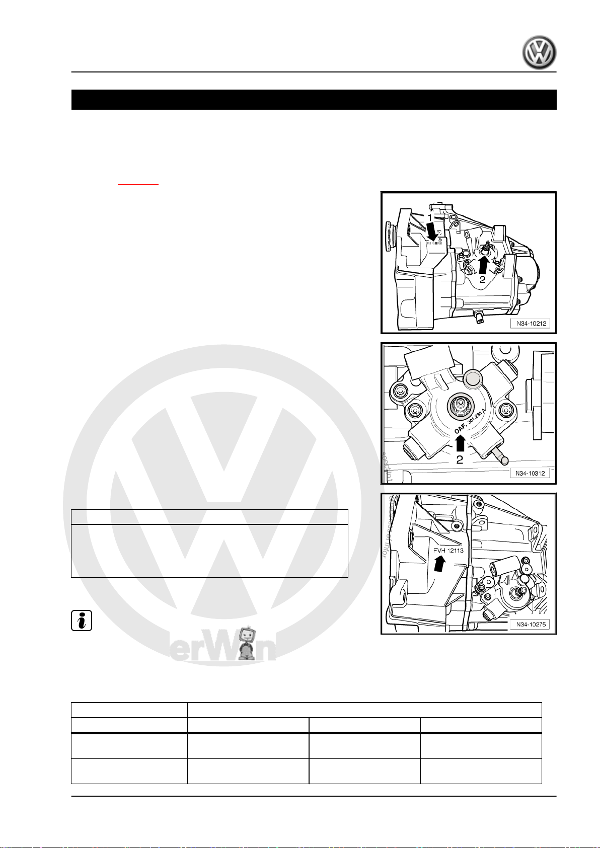
1.1 Location on gearbox
Code letters and date of manufacture -arrow 1- Manual gearbox
0AF -arrow 2-
Manual gearbox 0AF -arrow 2-
Identification code and date of gearbox manufacture -arrow-
Example: FVH 12 11 3
Additional data provide information about the production facility.
Note
The gearbox code also appears on the vehicle identification
Identification
plates.
I I I I
I I I I
Day Month Year (2003) of
code
manufacture
Jetta 2006 ➤ , Golf Variant 2008 ➤
1.2 Identification codes, assembly allocation, capacities
Manual gearbox 5-speed 0AF
Identification code FVH JHT
Manufac‐
tured
Allocation Model Jetta 2006 ▸
from
to
Golf Variant 2008 ▸
05.05 11.06
Jetta 2006 ▸
Golf Variant 2008 ▸
1. Gearbox identification 1

P
r
o
t
e
c
t
e
d
b
y
c
o
p
y
r
i
g
h
t
.
C
o
p
y
i
n
g
f
o
r
p
r
i
v
a
t
e
o
r
c
o
m
m
e
r
c
i
a
l
p
u
r
p
o
s
e
s
,
i
n
p
a
r
t
o
r
i
n
w
h
o
l
e
,
i
s
n
o
t
p
e
r
m
i
t
t
e
d
u
n
l
e
s
s
a
u
t
h
o
r
i
s
e
d
b
y
V
o
l
k
s
w
a
g
e
n
A
G
.
V
o
l
k
s
w
a
g
e
n
A
G
d
o
e
s
n
o
t
g
u
a
r
a
n
t
e
e
o
r
a
c
c
e
p
t
a
n
y
l
i
a
b
i
l
i
t
y
w
i
t
h
r
e
s
p
e
c
t
t
o
t
h
e
c
o
r
r
e
c
t
n
e
s
s
o
f
i
n
f
o
r
m
a
t
i
o
n
i
n
t
h
i
s
d
o
c
u
m
e
n
t
.
C
o
p
y
r
i
g
h
t
b
y
V
o
l
k
s
w
a
g
e
n
A
G
.
Jetta 2006 ➤ , Golf Variant 2008 ➤
5-speed manual gearbox 0AF - Edition 08.2007
Manual gearbox 5-speed 0AF
Identification code FVH JHT
Ratio
Engine 1.6 l - 75 kW 1.6 l - 75 kW
Final drive 68 : 15 = 4.533 68 : 15 = 4.533
Z1 : Z2
Capacity of manual gear‐
2.0 l 2.0 l
box
Drive shaft flange ∅ 100 mm 100 mm
The following data can be found in the ⇒ Electronic parts cata‐
logue “ETKA” .
♦ Individual gear ratios
♦ Gear oil
♦ Clutch allocation
2 Rep. Gr.00 - Technical data
P
r
o
t
e
c
t
e
d
b
y
c
o
p
y
r
i
g
h
t
.
C
o
p
y
i
n
g
f
o
r
p
r
i
v
a
t
e
o
r
c
o
m
m
e
r
c
i
a
l
p
u
r
p
o
s
e
s
,
i
n
p
a
r
t
o
r
i
n
w
h
o
l
e
,
i
s
n
o
t
p
e
r
m
i
t
t
e
d
u
n
l
e
s
s
a
u
t
h
o
r
i
s
e
d
b
y
V
o
l
k
s
w
a
g
e
n
A
G
.
V
o
l
k
s
w
a
g
e
n
A
G
d
o
e
s
n
o
t
g
u
a
r
a
n
t
e
e
o
r
a
c
c
e
p
t
a
n
y
l
i
a
b
i
l
i
t
y
w
i
t
h
r
e
s
p
e
c
t
t
o
t
h
e
c
o
r
r
e
c
t
n
e
s
s
o
f
i
n
f
o
r
m
a
t
i
o
n
i
n
t
h
i
s
d
o
c
u
m
e
n
t
.
C
o
p
y
r
i
g
h
t
b
y
V
o
l
k
s
w
a
g
e
n
A
G
.
5-speed manual gearbox 0AF - Edition 08.2007
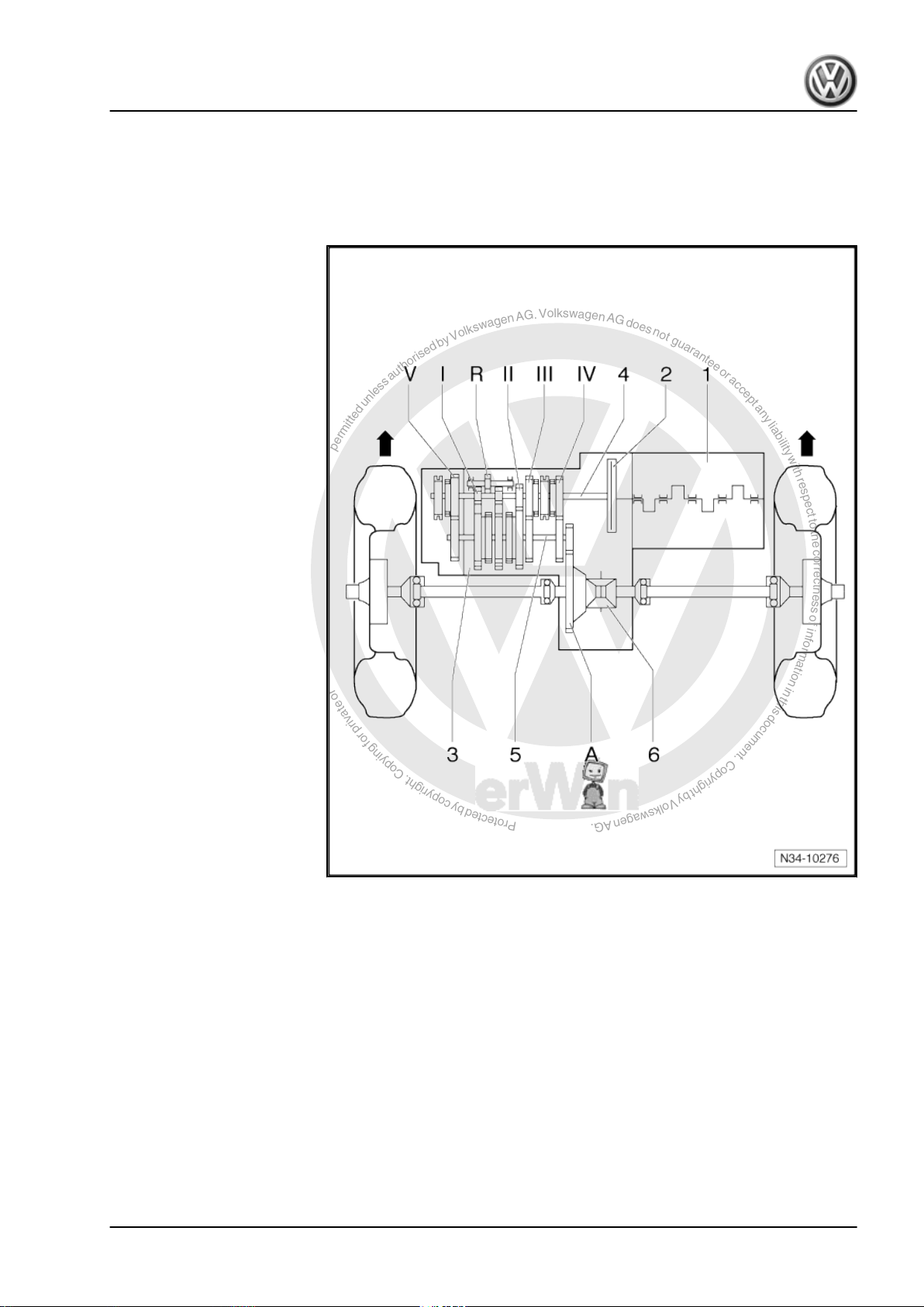
2 Overview - power transmission
Designation
-Arrows- indicate direction of travel.
1 - Engine
2 - Clutch
3 - Manual gearbox
4 - Input shaft
5 - Output shaft
6 - Differential
Jetta 2006 ➤ , Golf Variant 2008 ➤
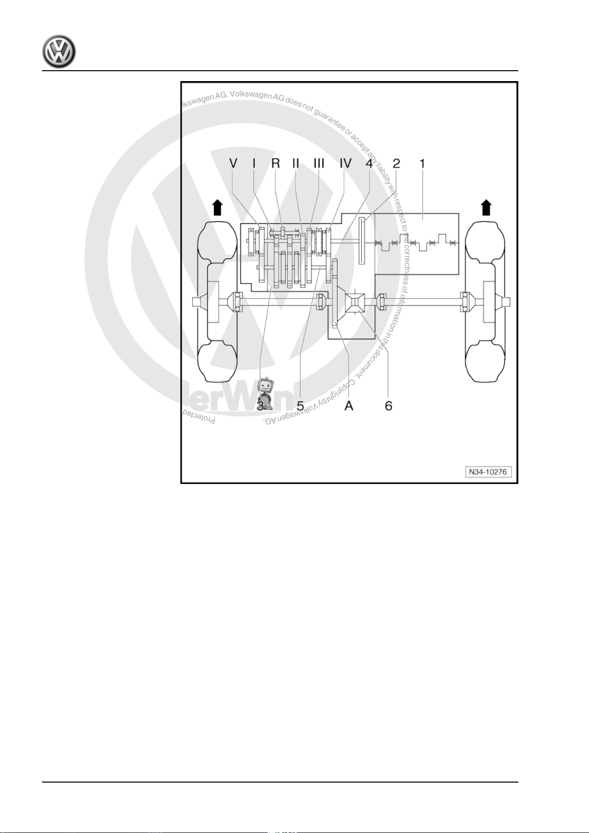
Gears
-Arrows- indicate direction of travel.
2. Overview - power transmission 3
P
r
o
t
e
c
t
e
d
b
y
c
o
p
y
r
i
g
h
t
.
C
o
p
y
i
n
g
f
o
r
p
r
i
v
a
t
e
o
r
c
o
m
m
e
r
c
i
a
l
p
u
r
p
o
s
e
s
,
i
n
p
a
r
t
o
r
i
n
w
h
o
l
e
,
i
s
n
o
t
p
e
r
m
i
t
t
e
d
u
n
l
e
s
s
a
u
t
h
o
r
i
s
e
d
b
y
V
o
l
k
s
w
a
g
e
n
A
G
.
V
o
l
k
s
w
a
g
e
n
A
G
d
o
e
s
n
o
t
g
u
a
r
a
n
t
e
e
o
r
a
c
c
e
p
t
a
n
y
l
i
a
b
i
l
i
t
y
w
i
t
h
r
e
s
p
e
c
t
t
o
t
h
e
c
o
r
r
e
c
t
n
e
s
s
o
f
i
n
f
o
r
m
a
t
i
o
n
i
n
t
h
i
s
d
o
c
u
m
e
n
t
.
C
o
p
y
r
i
g
h
t
b
y
V
o
l
k
s
w
a
g
e
n
A
G
.
Jetta 2006 ➤ , Golf Variant 2008 ➤
5-speed manual gearbox 0AF - Edition 08.2007
I - 1st gear
II - 2nd gear
III - 3rd gear
IV - 4th gear
V - 5th gear
R - Reverse gear
A - Final drive
4 Rep. Gr.00 - Technical data
P
r
o
t
e
c
t
e
d
b
y
c
o
p
y
r
i
g
h
t
.
C
o
p
y
i
n
g
f
o
r
p
r
i
v
a
t
e
o
r
c
o
m
m
e
r
c
i
a
l
p
u
r
p
o
s
e
s
,
i
n
p
a
r
t
o
r
i
n
w
h
o
l
e
,
i
s
n
o
t
p
e
r
m
i
t
t
e
d
u
n
l
e
s
s
a
u
t
h
o
r
i
s
e
d
b
y
V
o
l
k
s
w
a
g
e
n
A
G
.
V
o
l
k
s
w
a
g
e
n
A
G
d
o
e
s
n
o
t
g
u
a
r
a
n
t
e
e
o
r
a
c
c
e
p
t
a
n
y
l
i
a
b
i
l
i
t
y
w
i
t
h
r
e
s
p
e
c
t
t
o
t
h
e
c
o
r
r
e
c
t
n
e
s
s
o
f
i
n
f
o
r
m
a
t
i
o
n
i
n
t
h
i
s
d
o
c
u
m
e
n
t
.
C
o
p
y
r
i
g
h
t
b
y
V
o
l
k
s
w
a
g
e
n
A
G
.
3 Calculating overall gear ratio “i”
Example:
Drive gear ZG1 = 49 ZA1 = 16
Driven gear ZG2 = 38 ZA2 = 67
i = Z2 : Z1
1)
iG = Gear ratio = ZG2 : ZG1 = 38 : 49 = 0.776
iA = Final drive ratio = ZA2 : ZA1 = 67 : 16 = 4.188
i
= Overall ratio = iG x iA = 0.776 x 4.188 = 3.250
total
1) Z1 = No. of teeth on driving gear, Z2 = No. of teeth on driven gear
5th gear Final drive
5-speed manual gearbox 0AF - Edition 08.2007
Jetta 2006 ➤ , Golf Variant 2008 ➤
3. Calculating overall gear ratio “i” 5
P
r
o
t
e
c
t
e
d
b
y
c
o
p
y
r
i
g
h
t
.
C
o
p
y
i
n
g
f
o
r
p
r
i
v
a
t
e
o
r
c
o
m
m
e
r
c
i
a
l
p
u
r
p
o
s
e
s
,
i
n
p
a
r
t
o
r
i
n
w
h
o
l
e
,
i
s
n
o
t
p
e
r
m
i
t
t
e
d
u
n
l
e
s
s
a
u
t
h
o
r
i
s
e
d
b
y
V
o
l
k
s
w
a
g
e
n
A
G
.
V
o
l
k
s
w
a
g
e
n
A
G
d
o
e
s
n
o
t
g
u
a
r
a
n
t
e
e
o
r
a
c
c
e
p
t
a
n
y
l
i
a
b
i
l
i
t
y
w
i
t
h
r
e
s
p
e
c
t
t
o
t
h
e
c
o
r
r
e
c
t
n
e
s
s
o
f
i
n
f
o
r
m
a
t
i
o
n
i
n
t
h
i
s
d
o
c
u
m
e
n
t
.
C
o
p
y
r
i
g
h
t
b
y
V
o
l
k
s
w
a
g
e
n
A
G
.
Jetta 2006 ➤ , Golf Variant 2008 ➤
5-speed manual gearbox 0AF - Edition 08.2007
4 General repair notes
To ensure perfect and successful gearbox repairs, the greatest
care and cleanliness as well as the use of good and proper tools
is essential. Of course, the basic rules for safety also apply during
repair work.
A number of instructions generally applicable to the various repair
procedures - which were previously repeated a number of times
at various places in the workshop manual are summarised under
the topic “components” ⇒ page 6 . They apply to this workshop
manual.
4.1 Components
4.1.1 Gearbox
♦ When installing the manual gearbox, ensure that the dowel
sleeves between the engine and gearbox are correctly seated.
♦ When installing mounting brackets or waxed components,
clean the contact surfaces. Contact surfaces must be free of
wax and grease.
♦ Allocate bolts and other components using ⇒ Electronic parts
catalogue “ETKA” .
♦ When changing a gearbox, fill with gear oil to lower edge of
filler hole.
♦ Capacities ⇒ page 1
4.1.2 Seals and sealing rings
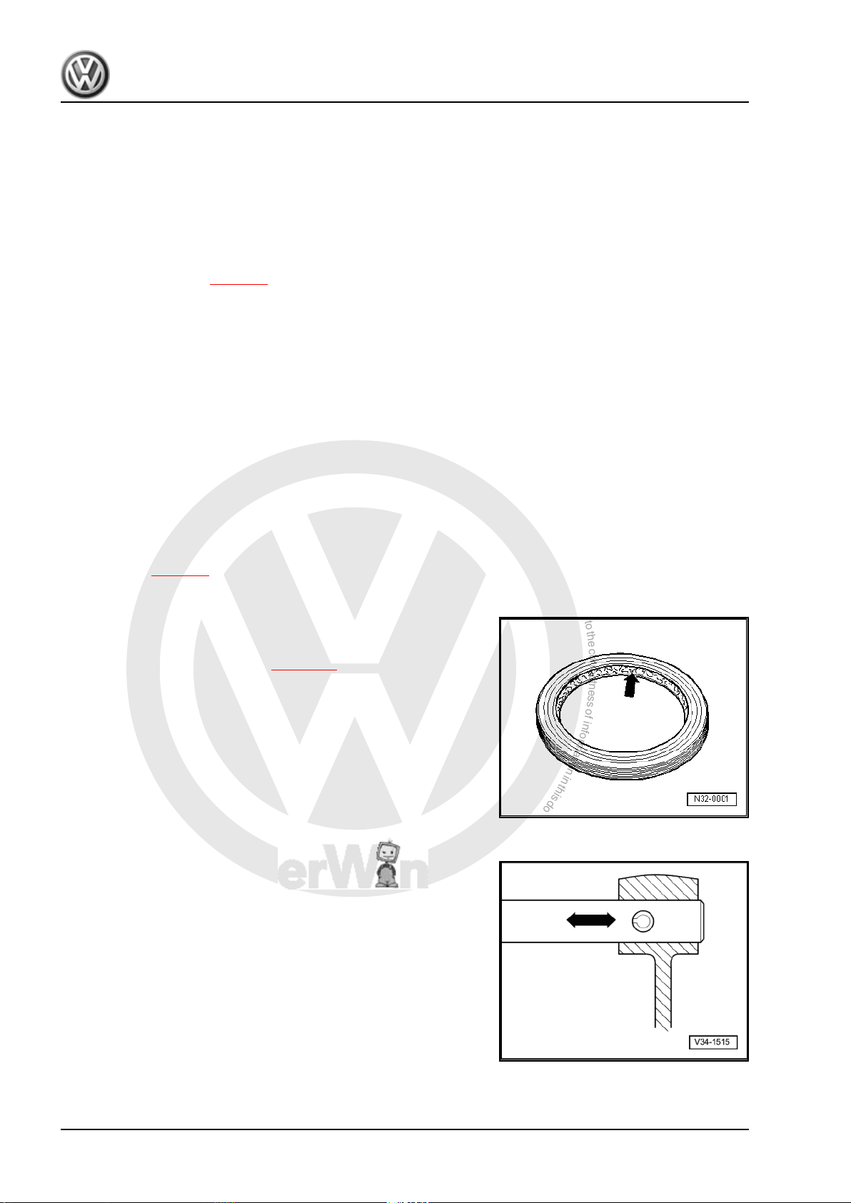
♦ Before installing oil seal, half-fill space between sealing lips
with sealing grease -G 052 128 A1- -arrow-.
♦ After installing, check oil level ⇒ page 72 .
♦ Thoroughly clean parting surfaces and apply sealant -AMV
188 200 03- .
♦ Apply sealant uniformly but not too thick.
4.1.3 Locking devices
♦ Renew retaining rings.
♦ Do not overstretch retaining rings.
♦ Retaining rings must locate properly in grooves.
♦ Renew spring pins. Installation position: slot longitudinal to line
of force.
6 Rep. Gr.00 - Technical data
P
r
o
t
e
c
t
e
d
b
y
c
o
p
y
r
i
g
h
t
.
C
o
p
y
i
n
g
f
o
r
p
r
i
v
a
t
e
o
r
c
o
m
m
e
r
c
i
a
l
p
u
r
p
o
s
e
s
,
i
n
p
a
r
t
o
r
i
n
w
h
o
l
e
,
i
s
n
o
t
p
e
r
m
i
t
t
e
d
u
n
l
e
s
s
a
u
t
h
o
r
i
s
e
d
b
y
V
o
l
k
s
w
a
g
e
n
A
G
.
V
o
l
k
s
w
a
g
e
n
A
G
d
o
e
s
n
o
t
g
u
a
r
a
n
t
e
e
o
r
a
c
c
e
p
t
a
n
y
l
i
a
b
i
l
i
t
y
w
i
t
h
r
e
s
p
e
c
t
t
o
t
h
e
c
o
r
r
e
c
t
n
e
s
s
o
f
i
n
f
o
r
m
a
t
i
o
n
i
n
t
h
i
s
d
o
c
u
m
e
n
t
.
C
o
p
y
r
i
g
h
t
b
y
V
o
l
k
s
w
a
g
e
n
A
G
.
5-speed manual gearbox 0AF - Edition 08.2007
4.1.4 Nuts and bolts
♦ Loosen and tighten securing bolts and nuts for covers and
housings diagonally.
♦ Do not cant especially delicate parts, such as clutch pressure
plates. Loosen and tighten bolts and nuts in stages in a diag‐
onal sequence.
♦ Torque settings are specified for unoiled bolts and nuts.
♦ Always renew self-locking bolts and nuts.
♦ Ensure with threaded connections that contact surfaces as
well as nuts and bolts are rewaxed only after assembly, if nec‐
essary.
♦ Use a thread chaser to clear residual locking fluid from all
threaded holes into which self-locking bolts are to be screwed.
Otherwise there is a danger of bolts shearing when subse‐
quently being removed.
4.1.5 Bearings
♦ Install new tapered roller bearings as supplied and do not lu‐
bricate additionally.
♦ Install needle bearings with lettered side (thicker metal) to‐
wards fitting tool.
♦ Tapered roller bearings fitted to one shaft must be renewed as
a set. Use same make of bearings.
♦ Heat inner races to about 100° C with the inductive heater -
VAS 6414- before installing.
♦ Do not interchange outer or inner races of bearings of the
same size. The bearings are matched in pairs.
4.1.6 Shims
♦ Measure shims at several points with a micrometer. The var‐
ious thicknesses make it possible to achieve the exact shim
thickness required.
♦ Check for burrs and damage.
♦ Install only flawless shims.
4.1.7 Synchro-rings
♦ Do not interchange. When reusing synchro-rings, always fit to
the same gear.
♦ Check for wear and renew if necessary.
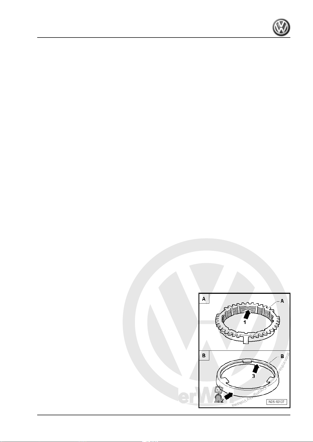
♦ Check grooves -arrow 1- of synchro-ring -A- and inner ring for
flat spots (worn grooves).
♦ If synchro-rings are coated, coating must not be damaged.
♦ If an intermediate ring -B- is installed, check the outer friction
surface -arrow 2- and inner friction surface -arrow 3- of this
intermediate ring for “scoring”, “signs of abnormal wear” and
“blue discolouration (due to overheating)”.
♦ Check cone of synchromeshed gear for “scoring” and “signs
of abnormal wear”.
♦ Moisten synchromesh mechanism with gear oil before instal‐
ling.
Jetta 2006 ➤ , Golf Variant 2008 ➤
4. General repair notes 7

P
r
o
t
e
c
t
e
d
b
y
c
o
p
y
r
i
g
h
t
.
C
o
p
y
i
n
g
f
o
r
p
r
i
v
a
t
e
o
r
c
o
m
m
e
r
c
i
a
l
p
u
r
p
o
s
e
s
,
i
n
p
a
r
t
o
r
i
n
w
h
o
l
e
,
i
s
n
o
t
p
e
r
m
i
t
t
e
d
u
n
l
e
s
s
a
u
t
h
o
r
i
s
e
d
b
y
V
o
l
k
s
w
a
g
e
n
A
G
.
V
o
l
k
s
w
a
g
e
n
A
G
d
o
e
s
n
o
t
g
u
a
r
a
n
t
e
e
o
r
a
c
c
e
p
t
a
n
y
l
i
a
b
i
l
i
t
y
w
i
t
h
r
e
s
p
e
c
t
t
o
t
h
e
c
o
r
r
e
c
t
n
e
s
s
o
f
i
n
f
o
r
m
a
t
i
o
n
i
n
t
h
i
s
d
o
c
u
m
e
n
t
.
C
o
p
y
r
i
g
h
t
b
y
V
o
l
k
s
w
a
g
e
n
A
G
.
Jetta 2006 ➤ , Golf Variant 2008 ➤
5-speed manual gearbox 0AF - Edition 08.2007
4.1.8 Gear wheels
♦ Before installing, clean and heat with the inductive heater -
VAS 6414- to maximum 100° C.
4.1.9 Synchromeshed gears
♦ After assembly, check synchromeshed gears for slight play, or
for freedom of movement.
4.1.10 Clutch
♦ Ensure that the pressure plate does not cant: loosen and tight‐
en bolts diagonally and in several gradual stages.
♦ If the clutch has burnt out, thoroughly clean the bell housing
as well as the friction surface of flywheel with a cloth to reduce
the smell of burnt linings.
8 Rep. Gr.00 - Technical data

P
r
o
t
e
c
t
e
d
b
y
c
o
p
y
r
i
g
h
t
.
C
o
p
y
i
n
g
f
o
r
p
r
i
v
a
t
e
o
r
c
o
m
m
e
r
c
i
a
l
p
u
r
p
o
s
e
s
,
i
n
p
a
r
t
o
r
i
n
w
h
o
l
e
,
i
s
n
o
t
p
e
r
m
i
t
t
e
d
u
n
l
e
s
s
a
u
t
h
o
r
i
s
e
d
b
y
V
o
l
k
s
w
a
g
e
n
A
G
.
V
o
l
k
s
w
a
g
e
n
A
G
d
o
e
s
n
o
t
g
u
a
r
a
n
t
e
e
o
r
a
c
c
e
p
t
a
n
y
l
i
a
b
i
l
i
t
y
w
i
t
h
r
e
s
p
e
c
t
t
o
t
h
e
c
o
r
r
e
c
t
n
e
s
s
o
f
i
n
f
o
r
m
a
t
i
o
n
i
n
t
h
i
s
d
o
c
u
m
e
n
t
.
C
o
p
y
r
i
g
h
t
b
y
V
o
l
k
s
w
a
g
e
n
A
G
.
5-speed manual gearbox 0AF - Edition 08.2007
30 – Clutch
1 Fault finding, Power transmission
– Refer to ⇒ Fault finding, power transmission; Rep. Gr. 30 ;
Complaints about clutch and clutch mechanism and ⇒ Fault
finding, power transmission; Rep. Gr. 34 ; Complaints about
selector mechanism
Jetta 2006 ➤ , Golf Variant 2008 ➤
1. Fault finding, Power transmission 9
P
r
o
t
e
c
t
e
d
b
y
c
o
p
y
r
i
g
h
t
.
C
o
p
y
i
n
g
f
o
r
p
r
i
v
a
t
e
o
r
c
o
m
m
e
r
c
i
a
l
p
u
r
p
o
s
e
s
,
i
n
p
a
r
t
o
r
i
n
w
h
o
l
e
,
i
s
n
o
t
p
e
r
m
i
t
t
e
d
u
n
l
e
s
s
a
u
t
h
o
r
i
s
e
d
b
y
V
o
l
k
s
w
a
g
e
n
A
G
.
V
o
l
k
s
w
a
g
e
n
A
G
d
o
e
s
n
o
t
g
u
a
r
a
n
t
e
e
o
r
a
c
c
e
p
t
a
n
y
l
i
a
b
i
l
i
t
y
w
i
t
h
r
e
s
p
e
c
t
t
o
t
h
e
c
o
r
r
e
c
t
n
e
s
s
o
f
i
n
f
o
r
m
a
t
i
o
n
i
n
t
h
i
s
d
o
c
u
m
e
n
t
.
C
o
p
y
r
i
g
h
t
b
y
V
o
l
k
s
w
a
g
e
n
A
G
.
Jetta 2006 ➤ , Golf Variant 2008 ➤
5-speed manual gearbox 0AF - Edition 08.2007
2 Repairing clutch mechanism
2.1 Overview
Note
♦
Before disconnecting battery, obtain code for radio units having anti-theft coding.
♦
With ignition switched off, disconnect battery earth strap.
♦
⇒ Electrical system; Rep. Gr. 27 ; Disconnecting and connecting battery
♦
When reconnecting battery, refer to ⇒ Electrical system; Rep. Gr. 27 ; Disconnecting and connecting
battery .
♦
Lubricate all bearings and contact surfaces with grease -G 000 450 02- .
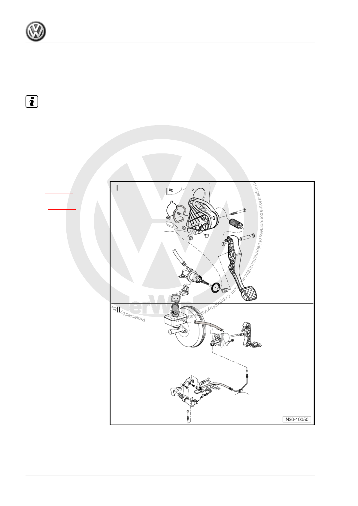
I - Assembly overview - pedal
cluster ⇒ page 11
II - Assembly overview - hy‐
draulics ⇒ page 24
10 Rep. Gr.30 - Clutch
P
r
o
t
e
c
t
e
d
b
y
c
o
p
y
r
i
g
h
t
.
C
o
p
y
i
n
g
f
o
r
p
r
i
v
a
t
e
o
r
c
o
m
m
e
r
c
i
a
l
p
u
r
p
o
s
e
s
,
i
n
p
a
r
t
o
r
i
n
w
h
o
l
e
,
i
s
n
o
t
p
e
r
m
i
t
t
e
d
u
n
l
e
s
s
a
u
t
h
o
r
i
s
e
d
b
y
V
o
l
k
s
w
a
g
e
n
A
G
.
V
o
l
k
s
w
a
g
e
n
A
G
d
o
e
s
n
o
t
g
u
a
r
a
n
t
e
e
o
r
a
c
c
e
p
t
a
n
y
l
i
a
b
i
l
i
t
y
w
i
t
h
r
e
s
p
e
c
t
t
o
t
h
e
c
o
r
r
e
c
t
n
e
s
s
o
f
i
n
f
o
r
m
a
t
i
o
n
i
n
t
h
i
s
d
o
c
u
m
e
n
t
.
C
o
p
y
r
i
g
h
t
b
y
V
o
l
k
s
w
a
g
e
n
A
G
.
5-speed manual gearbox 0AF - Edition 08.2007
2.2 Assembly overview - pedal cluster
Jetta 2006 ➤ , Golf Variant 2008 ➤
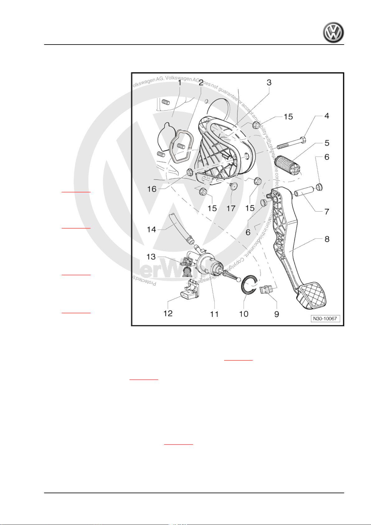
1 - Bulkhead
❑ With support for mount‐
ing bracket
2 - Seal
❑ Always renew
❑ Between mounting
bracket and bulkhead
❑ Self-adhesive
❑ Bond to mounting
bracket
3 - Mounting bracket
❑ For mounting clutch
pedal
❑ Removing and installing
⇒ page 16
4 - Bolt
5 - Over-centre spring
❑ Removing and installing
⇒ page 12
6 - Bearing bush
7 - Pivot pin
8 - Clutch pedal
❑ Removing and installing
⇒ page 14
9 - Retainer
❑ To remove and install,
separate master cylin‐
der from clutch pedal.
⇒ page 14
10 - Seal
❑ Always renew
❑ Between master cylinder and mounting bracket
11 - Master cylinder
❑ Removing and installing after removal of mounting bracket ⇒ page 19
12 - Clutch position sender -G476-
❑ Removing and installing ⇒ page 21
❑ Can be checked in “guided fault finding” of vehicle diagnosis, testing and information system -VAS 5051❑ The clutch position sender -G476- is identified as clutch pedal switch -F36- in “guided fault finding”.
13 - Clip
❑ Pull out clip to stop to remove and install pipe/hose line or plastic line
14 - Supply hose
❑ Rubber
❑ From 12.05, plastic in some vehicles ⇒ page 25
15 - Self-locking hexagon nut, 25 Nm
❑ Qty. 3
❑ For mounting bracket on bulkhead
❑ Always renew
2. Repairing clutch mechanism 11
P
r
o
t
e
c
t
e
d
b
y
c
o
p
y
r
i
g
h
t
.
C
o
p
y
i
n
g
f
o
r
p
r
i
v
a
t
e
o
r
c
o
m
m
e
r
c
i
a
l
p
u
r
p
o
s
e
s
,
i
n
p
a
r
t
o
r
i
n
w
h
o
l
e
,
i
s
n
o
t
p
e
r
m
i
t
t
e
d
u
n
l
e
s
s
a
u
t
h
o
r
i
s
e
d
b
y
V
o
l
k
s
w
a
g
e
n
A
G
.
V
o
l
k
s
w
a
g
e
n
A
G
d
o
e
s
n
o
t
g
u
a
r
a
n
t
e
e
o
r
a
c
c
e
p
t
a
n
y
l
i
a
b
i
l
i
t
y
w
i
t
h
r
e
s
p
e
c
t
t
o
t
h
e
c
o
r
r
e
c
t
n
e
s
s
o
f
i
n
f
o
r
m
a
t
i
o
n
i
n
t
h
i
s
d
o
c
u
m
e
n
t
.
C
o
p
y
r
i
g
h
t
b
y
V
o
l
k
s
w
a
g
e
n
A
G
.
Jetta 2006 ➤ , Golf Variant 2008 ➤
5-speed manual gearbox 0AF - Edition 08.2007
16 - Hexagon nut, 25 Nm
❑ Always renew
17 - Stop
❑ For clutch pedal
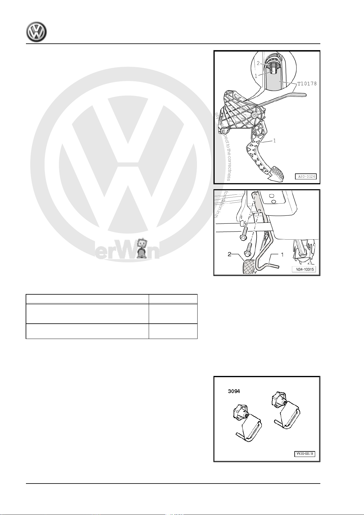
2.3 Removing and installing over-centre spring
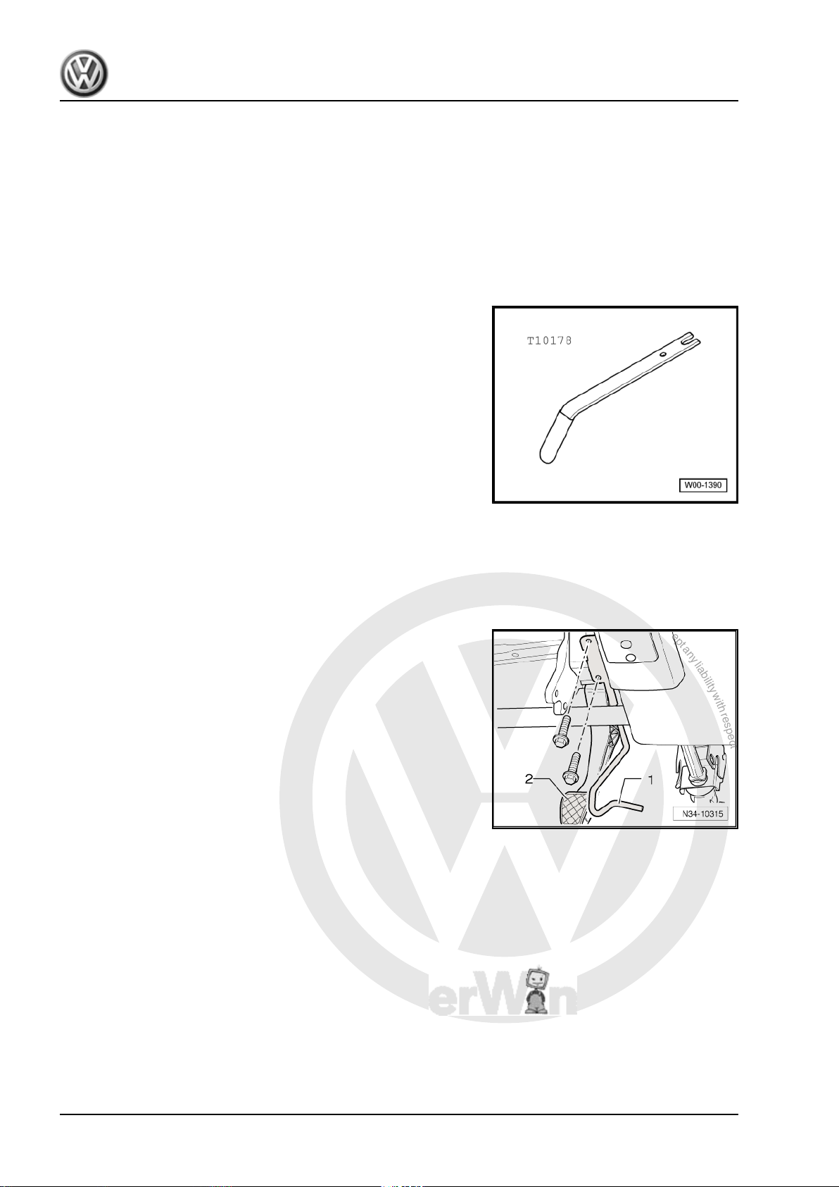
Special tools and workshop equipment required
♦ Release tool -T10178-
2.3.1 Removing
– Push driver seat as far back as possible and put steering wheel
in highest position.
– Remove trim and cover below trim on drive side ⇒ General
body repairs, interior; Rep. Gr. 68 .
– Now unbolt crash bar -1- from in front of clutch pedal -2-.
12 Rep. Gr.30 - Clutch
P
r
o
t
e
c
t
e
d
b
y
c
o
p
y
r
i
g
h
t
.
C
o
p
y
i
n
g
f
o
r
p
r
i
v
a
t
e
o
r
c
o
m
m
e
r
c
i
a
l
p
u
r
p
o
s
e
s
,
i
n
p
a
r
t
o
r
i
n
w
h
o
l
e
,
i
s
n
o
t
p
e
r
m
i
t
t
e
d
u
n
l
e
s
s
a
u
t
h
o
r
i
s
e
d
b
y
V
o
l
k
s
w
a
g
e
n
A
G
.
V
o
l
k
s
w
a
g
e
n
A
G
d
o
e
s
n
o
t
g
u
a
r
a
n
t
e
e
o
r
a
c
c
e
p
t
a
n
y
l
i
a
b
i
l
i
t
y
w
i
t
h
r
e
s
p
e
c
t
t
o
t
h
e
c
o
r
r
e
c
t
n
e
s
s
o
f
i
n
f
o
r
m
a
t
i
o
n
i
n
t
h
i
s
d
o
c
u
m
e
n
t
.
C
o
p
y
r
i
g
h
t
b
y
V
o
l
k
s
w
a
g
e
n
A
G
.
Jetta 2006 ➤ , Golf Variant 2008 ➤
5-speed manual gearbox 0AF - Edition 08.2007
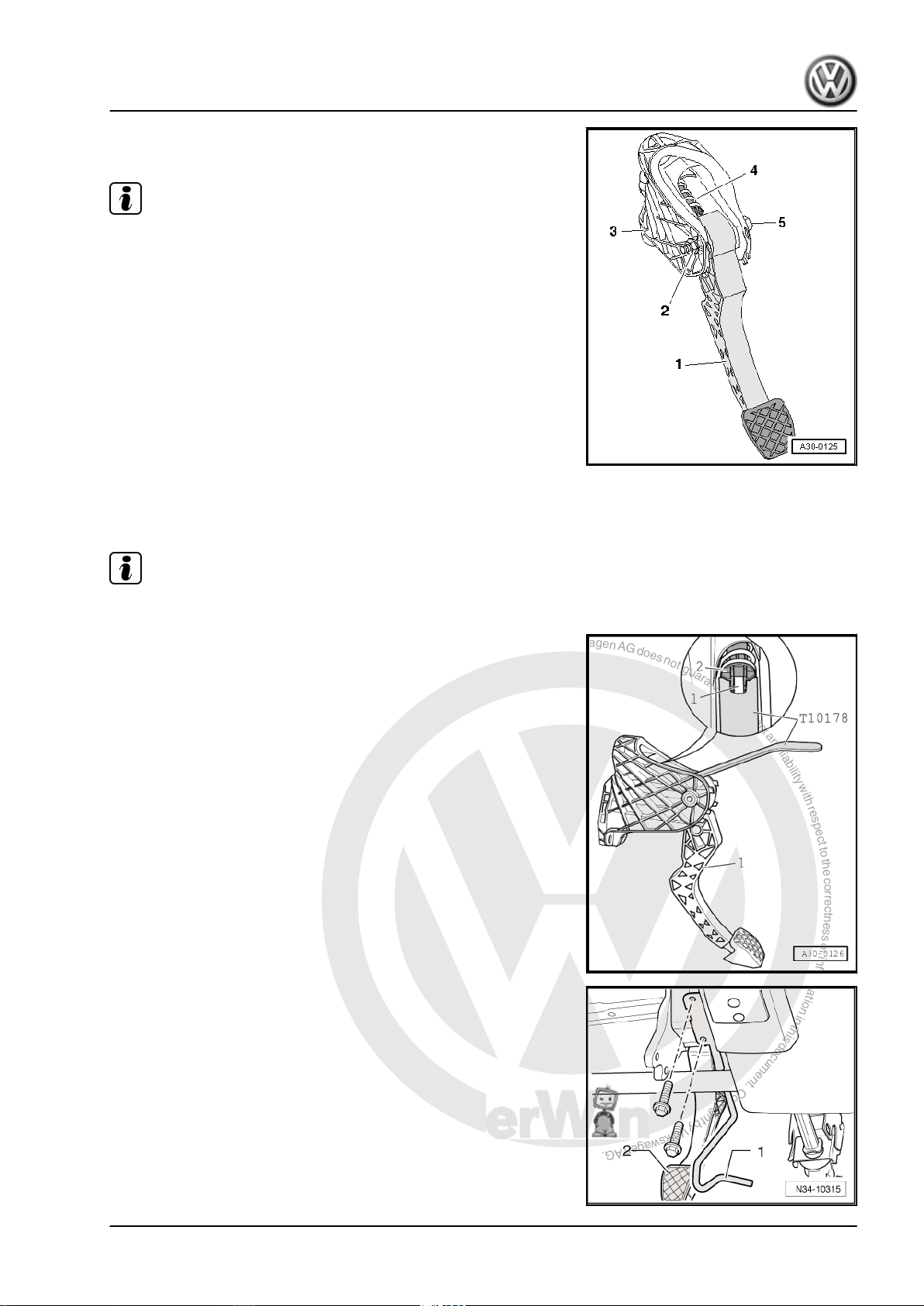
– Unbolt clutch pedal -1- from mounting bracket -3- by removing
nut -2- and pulling out bolt -5-.
Note
The clutch pedal remains hooked to operating rod of master cyl‐
inder.
– Swing clutch pedal down slightly and remove over-centre
spring -4- from mounting bracket.
2.3.2 Installing
Install in the reverse order of removal, observing the following:
Note
Renew self-locking nuts.
– Insert over-centre spring in mounting bracket from above while
holding end of spring with release tool -T10178- in installation
position.
– Insert tip of clutch pedal in bearing recess of over-centre
spring.
– Depress clutch pedal slightly, push bolt through and tighten
self-locking nut.
– Now bolt on crash bar -1- in front of clutch pedal -2-.
– Install trim and cover below trim on drive side ⇒ General body
repairs, interior; Rep. Gr. 68 .
2. Repairing clutch mechanism 13
P
r
o
t
e
c
t
e
d
b
y
c
o
p
y
r
i
g
h
t
.
C
o
p
y
i
n
g
f
o
r
p
r
i
v
a
t
e
o
r
c
o
m
m
e
r
c
i
a
l
p
u
r
p
o
s
e
s
,
i
n
p
a
r
t
o
r
i
n
w
h
o
l
e
,
i
s
n
o
t
p
e
r
m
i
t
t
e
d
u
n
l
e
s
s
a
u
t
h
o
r
i
s
e
d
b
y
V
o
l
k
s
w
a
g
e
n
A
G
.
V
o
l
k
s
w
a
g
e
n
A
G
d
o
e
s
n
o
t
g
u
a
r
a
n
t
e
e
o
r
a
c
c
e
p
t
a
n
y
l
i
a
b
i
l
i
t
y
w
i
t
h
r
e
s
p
e
c
t
t
o
t
h
e
c
o
r
r
e
c
t
n
e
s
s
o
f
i
n
f
o
r
m
a
t
i
o
n
i
n
t
h
i
s
d
o
c
u
m
e
n
t
.
C
o
p
y
r
i
g
h
t
b
y
V
o
l
k
s
w
a
g
e
n
A
G
.
Jetta 2006 ➤ , Golf Variant 2008 ➤
5-speed manual gearbox 0AF - Edition 08.2007
2.3.3 Torque settings
Component Nm
Clutch pedal to mounting bracket
♦ Renew self-locking nuts
25
Crash bar to steering column mounting
10
bracket
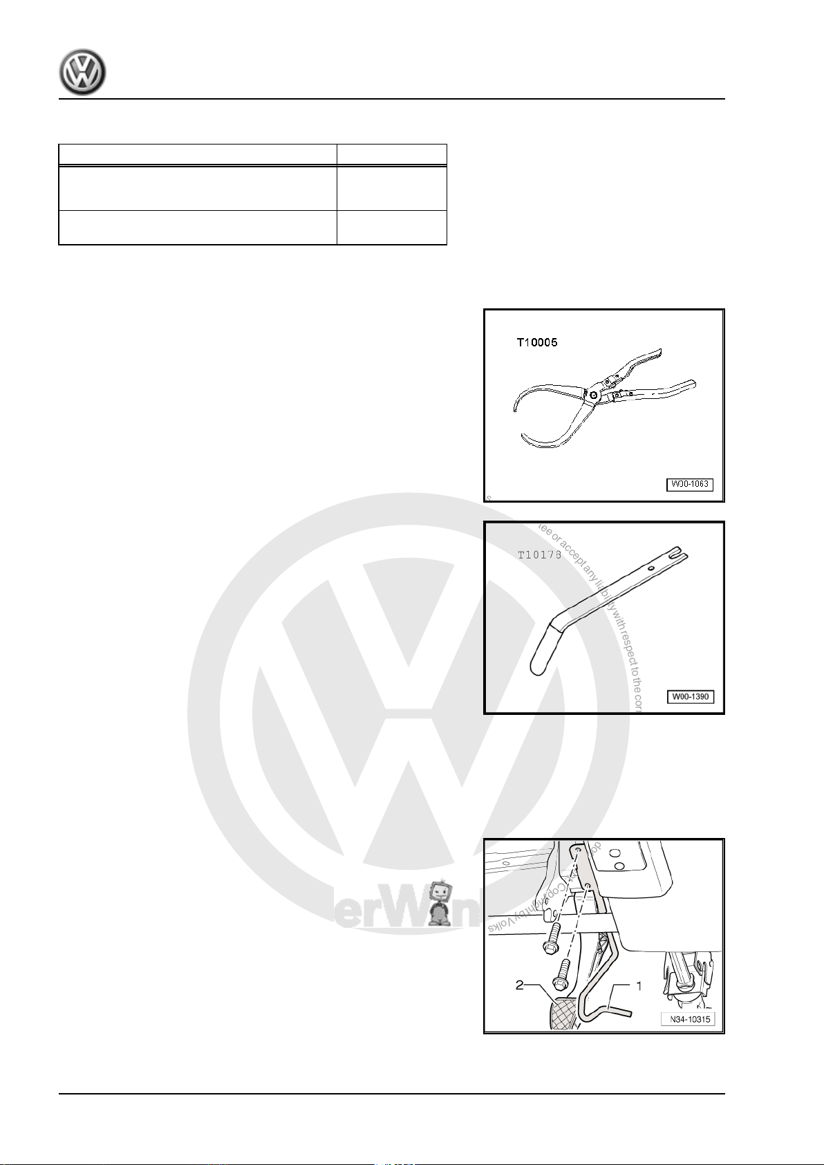
2.4 Removing and installing clutch pedal
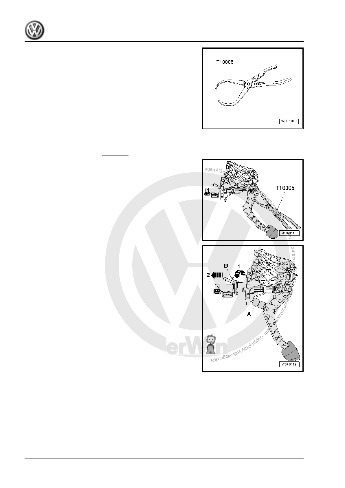
Special tools and workshop equipment required
♦ Pliers -T10005-
♦ Release tool -T10178-
2.4.1 Removing
– Push driver seat as far back as possible and put steering wheel
in highest position.
– Remove trim and cover below trim on drive side ⇒ General
body repairs, interior; Rep. Gr. 68 .
– Now unbolt crash bar -1- from in front of clutch pedal -2-.
14 Rep. Gr.30 - Clutch
P
r
o
t
e
c
t
e
d
b
y
c
o
p
y
r
i
g
h
t
.
C
o
p
y
i
n
g
f
o
r
p
r
i
v
a
t
e
o
r
c
o
m
m
e
r
c
i
a
l
p
u
r
p
o
s
e
s
,
i
n
p
a
r
t
o
r
i
n
w
h
o
l
e
,
i
s
n
o
t
p
e
r
m
i
t
t
e
d
u
n
l
e
s
s
a
u
t
h
o
r
i
s
e
d
b
y
V
o
l
k
s
w
a
g
e
n
A
G
.
V
o
l
k
s
w
a
g
e
n
A
G
d
o
e
s
n
o
t
g
u
a
r
a
n
t
e
e
o
r
a
c
c
e
p
t
a
n
y
l
i
a
b
i
l
i
t
y
w
i
t
h
r
e
s
p
e
c
t
t
o
t
h
e
c
o
r
r
e
c
t
n
e
s
s
o
f
i
n
f
o
r
m
a
t
i
o
n
i
n
t
h
i
s
d
o
c
u
m
e
n
t
.
C
o
p
y
r
i
g
h
t
b
y
V
o
l
k
s
w
a
g
e
n
A
G
.
5-speed manual gearbox 0AF - Edition 08.2007
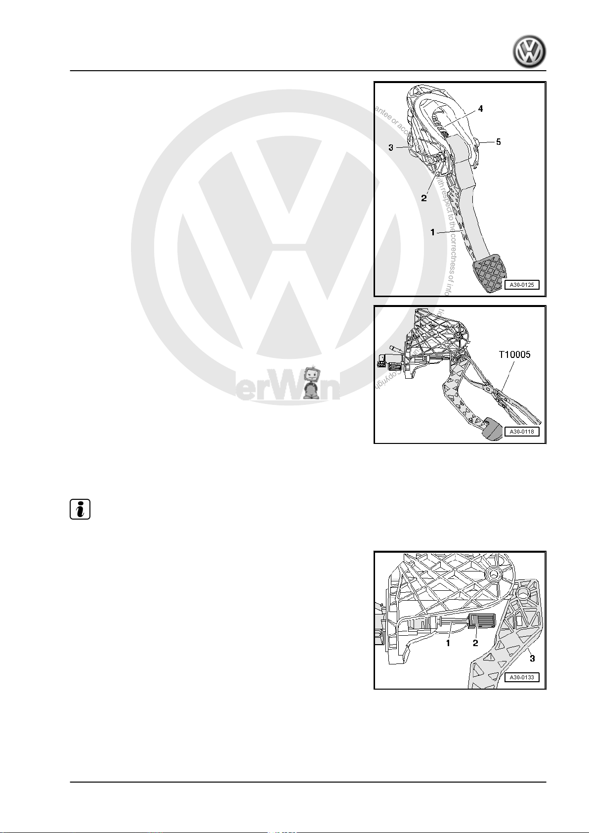
– Unbolt clutch pedal -1- from mounting bracket -3- by removing
nut -2- and pulling out bolt -5-.
– Swing clutch pedal forward slightly and remove over-centre
spring -4- from mounting bracket.
– Release clutch pedal from master cylinder with pliers -
T10005- .
– Remove clutch pedal.
Jetta 2006 ➤ , Golf Variant 2008 ➤
2.4.2 Installing
Install in the reverse order of removal, observing the following:
Note
Renew self-locking nuts.
– Attach retainer -2- to master cylinder operating rod -1-.
– Press retainer into notch in clutch pedal until it can be heard
to engage.
2. Repairing clutch mechanism 15
P
r
o
t
e
c
t
e
d
b
y
c
o
p
y
r
i
g
h
t
.
C
o
p
y
i
n
g
f
o
r
p
r
i
v
a
t
e
o
r
c
o
m
m
e
r
c
i
a
l
p
u
r
p
o
s
e
s
,
i
n
p
a
r
t
o
r
i
n
w
h
o
l
e
,
i
s
n
o
t
p
e
r
m
i
t
t
e
d
u
n
l
e
s
s
a
u
t
h
o
r
i
s
e
d
b
y
V
o
l
k
s
w
a
g
e
n
A
G
.
V
o
l
k
s
w
a
g
e
n
A
G
d
o
e
s
n
o
t
g
u
a
r
a
n
t
e
e
o
r
a
c
c
e
p
t
a
n
y
l
i
a
b
i
l
i
t
y
w
i
t
h
r
e
s
p
e
c
t
t
o
t
h
e
c
o
r
r
e
c
t
n
e
s
s
o
f
i
n
f
o
r
m
a
t
i
o
n
i
n
t
h
i
s
d
o
c
u
m
e
n
t
.
C
o
p
y
r
i
g
h
t
b
y
V
o
l
k
s
w
a
g
e
n
A
G
.
Jetta 2006 ➤ , Golf Variant 2008 ➤
5-speed manual gearbox 0AF - Edition 08.2007
– Insert over-centre spring in mounting bracket from above while
holding end of spring with release tool -T10178- in installation
position.
– Insert tip of clutch pedal in bearing recess of over-centre
spring.
– Depress clutch pedal slightly, push bolt through and tighten
self-locking nut.
– Now bolt on crash bar -1- in front of clutch pedal -2-.
– Install trim and cover below trim on drive side ⇒ General body
repairs, interior; Rep. Gr. 68 .
2.4.3 Torque settings
Component Nm
Clutch pedal to mounting bracket
25
♦ Renew self-locking nuts
Crash bar to steering column mounting
10
bracket
2.5 Removing and installing mounting bracket
Special tools and workshop equipment required
♦ Hose clamps to 25 mm Ø -3094-
16 Rep. Gr.30 - Clutch
P
r
o
t
e
c
t
e
d
b
y
c
o
p
y
r
i
g
h
t
.
C
o
p
y
i
n
g
f
o
r
p
r
i
v
a
t
e
o
r
c
o
m
m
e
r
c
i
a
l
p
u
r
p
o
s
e
s
,
i
n
p
a
r
t
o
r
i
n
w
h
o
l
e
,
i
s
n
o
t
p
e
r
m
i
t
t
e
d
u
n
l
e
s
s
a
u
t
h
o
r
i
s
e
d
b
y
V
o
l
k
s
w
a
g
e
n
A
G
.
V
o
l
k
s
w
a
g
e
n
A
G
d
o
e
s
n
o
t
g
u
a
r
a
n
t
e
e
o
r
a
c
c
e
p
t
a
n
y
l
i
a
b
i
l
i
t
y
w
i
t
h
r
e
s
p
e
c
t
t
o
t
h
e
c
o
r
r
e
c
t
n
e
s
s
o
f
i
n
f
o
r
m
a
t
i
o
n
i
n
t
h
i
s
d
o
c
u
m
e
n
t
.
C
o
p
y
r
i
g
h
t
b
y
V
o
l
k
s
w
a
g
e
n
A
G
.
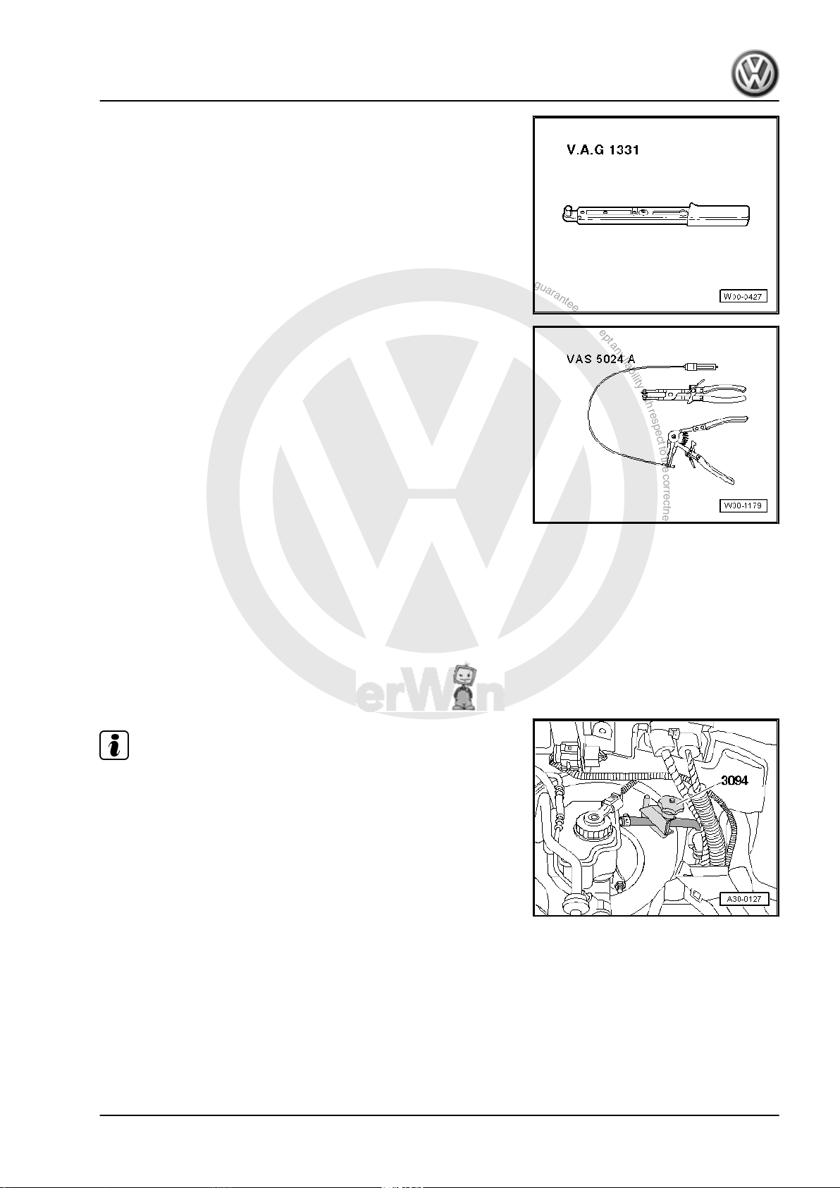
5-speed manual gearbox 0AF - Edition 08.2007
Torque wrench -V.A.G 1331-
Spring-type clip pliers -VAS 5024 A-
2.5.1 Removing
– First check whether a coded radio is fitted. If so, obtain anti-
theft code.
– With ignition switched off, disconnect battery ⇒ Electrical sys‐
tem; Rep. Gr. 27 ; Disconnecting and connecting battery .
– Remove complete air filter housing if it is near battery ⇒ Rep.
Gr. 24 ; Repairing injection system .
– Remove battery and battery tray ⇒ Electrical system; Rep.
Gr. 27 ; Removing and installing battery .
Jetta 2006 ➤ , Golf Variant 2008 ➤
Note
♦
During the following work, ensure that no brake fluid lands on
longitudinal member or gearbox. If this does happen, clean the
affected areas thoroughly.
♦
Place a lint-free cloth under the master cylinder.
– Clamp off supply hose to master cylinder using hose clamp
-3094- .
2. Repairing clutch mechanism 17
P
r
o
t
e
c
t
e
d
b
y
c
o
p
y
r
i
g
h
t
.
C
o
p
y
i
n
g
f
o
r
p
r
i
v
a
t
e
o
r
c
o
m
m
e
r
c
i
a
l
p
u
r
p
o
s
e
s
,
i
n
p
a
r
t
o
r
i
n
w
h
o
l
e
,
i
s
n
o
t
p
e
r
m
i
t
t
e
d
u
n
l
e
s
s
a
u
t
h
o
r
i
s
e
d
b
y
V
o
l
k
s
w
a
g
e
n
A
G
.
V
o
l
k
s
w
a
g
e
n
A
G
d
o
e
s
n
o
t
g
u
a
r
a
n
t
e
e
o
r
a
c
c
e
p
t
a
n
y
l
i
a
b
i
l
i
t
y
w
i
t
h
r
e
s
p
e
c
t
t
o
t
h
e
c
o
r
r
e
c
t
n
e
s
s
o
f
i
n
f
o
r
m
a
t
i
o
n
i
n
t
h
i
s
d
o
c
u
m
e
n
t
.
C
o
p
y
r
i
g
h
t
b
y
V
o
l
k
s
w
a
g
e
n
A
G
.
Jetta 2006 ➤ , Golf Variant 2008 ➤
5-speed manual gearbox 0AF - Edition 08.2007
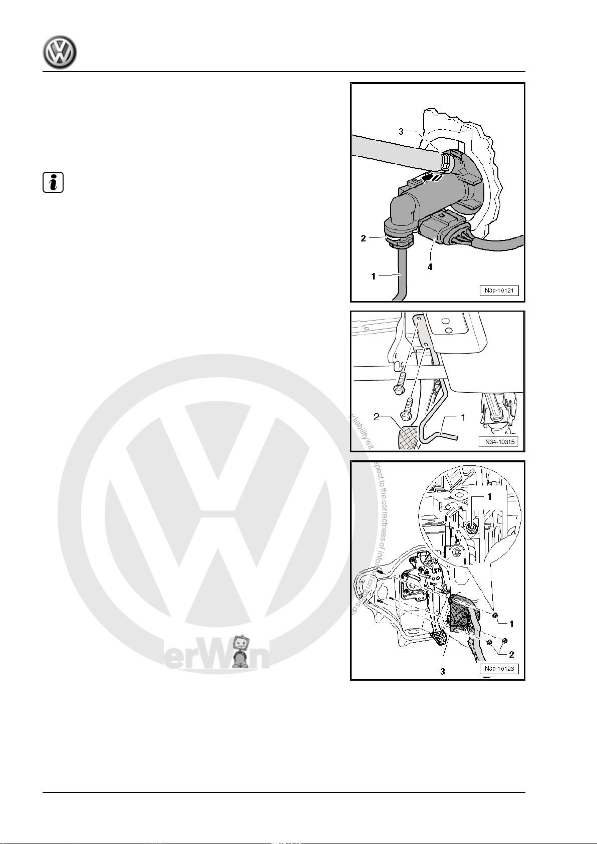
– Loosen spring-type clip -3- with spring-type clip pliers -VAS
5024- and pull supply hose off master cylinder.
– Release securing clip -2- using screwdriver and pull pipe/hose
line or plastic line -1- off master cylinder.
– Unclip clutch position sender -G476- from master cylinder
-arrow- and remove with electrical connector attached -4-.
Note
When performing work in the footwell, put cloths on the carpet to
protect it from possible brake fluid spills.
– Remove trim and cover below trim on drive side ⇒ General
body repairs, interior; Rep. Gr. 68 .
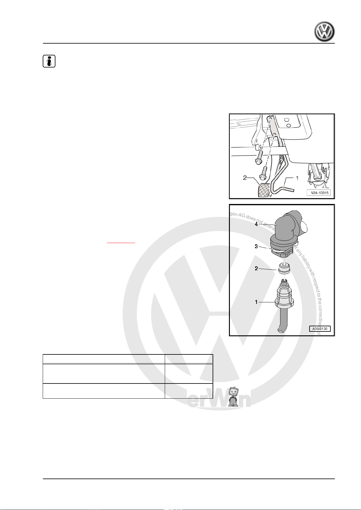
– Now unbolt crash bar -1- from in front of clutch pedal -2-.
– Remove securing nuts -1- and -2-.
The upper securing nut -1- is accessible between the relay carrier
and the steering column trim.
– Remove mounting bracket -3-.
2.5.2 Installing
Install in the reverse order of removal, observing the following:
18 Rep. Gr.30 - Clutch
P
r
o
t
e
c
t
e
d
b
y
c
o
p
y
r
i
g
h
t
.
C
o
p
y
i
n
g
f
o
r
p
r
i
v
a
t
e
o
r
c
o
m
m
e
r
c
i
a
l
p
u
r
p
o
s
e
s
,
i
n
p
a
r
t
o
r
i
n
w
h
o
l
e
,
i
s
n
o
t
p
e
r
m
i
t
t
e
d
u
n
l
e
s
s
a
u
t
h
o
r
i
s
e
d
b
y
V
o
l
k
s
w
a
g
e
n
A
G
.
V
o
l
k
s
w
a
g
e
n
A
G
d
o
e
s
n
o
t
g
u
a
r
a
n
t
e
e
o
r
a
c
c
e
p
t
a
n
y
l
i
a
b
i
l
i
t
y
w
i
t
h
r
e
s
p
e
c
t
t
o
t
h
e
c
o
r
r
e
c
t
n
e
s
s
o
f
i
n
f
o
r
m
a
t
i
o
n
i
n
t
h
i
s
d
o
c
u
m
e
n
t
.
C
o
p
y
r
i
g
h
t
b
y
V
o
l
k
s
w
a
g
e
n
A
G
.
5-speed manual gearbox 0AF - Edition 08.2007
Note
♦
Renew self-locking nuts.
♦
Renew hose clips.
♦
Allocate all components according to ⇒ Electronic parts cata‐
logue “ETKA” .
– Now bolt on crash bar -1- in front of clutch pedal -2-.
– Install trim and cover below trim on drive side ⇒ General body
repairs, interior; Rep. Gr. 68 .
Jetta 2006 ➤ , Golf Variant 2008 ➤
– Push pipe/hose line or plastic line -1- with seal -2- onto con‐
nection of master cylinder -4- until securing clip -3- engages
audibly.
– Test line by tugging on it.
– Bleed clutch system ⇒ page 27 .
– Install battery ⇒ Electrical system; Rep. Gr. 27 ; Removing
and installing battery .
– If removed, install complete air filter housing ⇒ Rep. Gr. 24 ;
Repairing injection system .
2.5.3 Torque settings
Component Nm
Mounting bracket to body
♦ Renew self-locking nuts
Crash bar to steering column mounting
bracket
2.6 Removing and installing master cylinder
25
10
Special tools and workshop equipment required
2. Repairing clutch mechanism 19
P
r
o
t
e
c
t
e
d
b
y
c
o
p
y
r
i
g
h
t
.
C
o
p
y
i
n
g
f
o
r
p
r
i
v
a
t
e
o
r
c
o
m
m
e
r
c
i
a
l
p
u
r
p
o
s
e
s
,
i
n
p
a
r
t
o
r
i
n
w
h
o
l
e
,
i
s
n
o
t
p
e
r
m
i
t
t
e
d
u
n
l
e
s
s
a
u
t
h
o
r
i
s
e
d
b
y
V
o
l
k
s
w
a
g
e
n
A
G
.
V
o
l
k
s
w
a
g
e
n
A
G
d
o
e
s
n
o
t
g
u
a
r
a
n
t
e
e
o
r
a
c
c
e
p
t
a
n
y
l
i
a
b
i
l
i
t
y
w
i
t
h
r
e
s
p
e
c
t
t
o
t
h
e
c
o
r
r
e
c
t
n
e
s
s
o
f
i
n
f
o
r
m
a
t
i
o
n
i
n
t
h
i
s
d
o
c
u
m
e
n
t
.
C
o
p
y
r
i
g
h
t
b
y
V
o
l
k
s
w
a
g
e
n
A
G
.
Jetta 2006 ➤ , Golf Variant 2008 ➤
5-speed manual gearbox 0AF - Edition 08.2007
♦ Pliers -T10005-
2.6.1 Removing
– Remove mounting bracket ⇒ page 16 .
– Release retainer for master cylinder operating rod using pliers
-T10005- .
– Insert spacer -A- between clutch pedal and stop and press
clutch pedal to spacer.
♦
Length of spacer = about 40 mm (e.g. 1/2" socket).
– Release securing bar -B- and pull master cylinder out of
mounting bracket -arrow 1- and -arrow 2-.
2.6.2 Installing
• Move clutch pedal to rest position at stop.
20 Rep. Gr.30 - Clutch
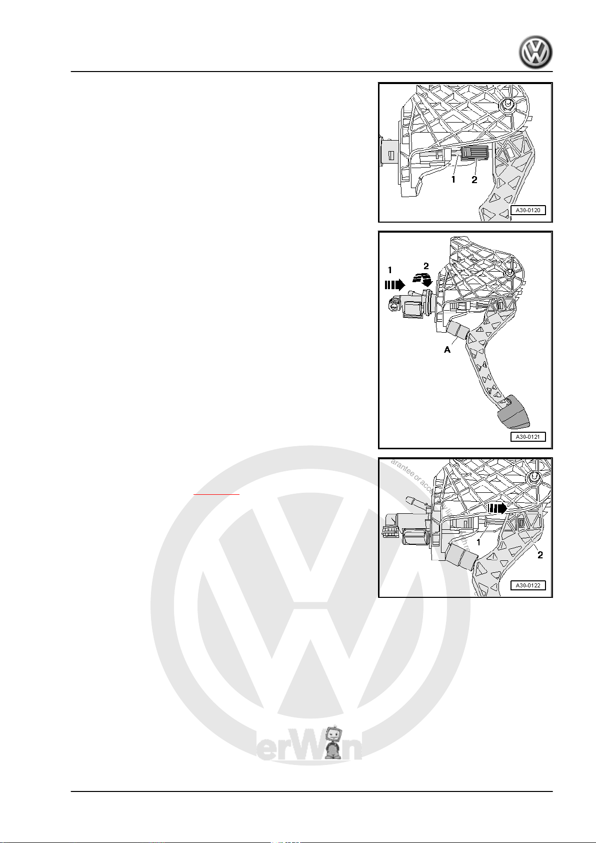
P
r
o
t
e
c
t
e
d
b
y
c
o
p
y
r
i
g
h
t
.
C
o
p
y
i
n
g
f
o
r
p
r
i
v
a
t
e
o
r
c
o
m
m
e
r
c
i
a
l
p
u
r
p
o
s
e
s
,
i
n
p
a
r
t
o
r
i
n
w
h
o
l
e
,
i
s
n
o
t
p
e
r
m
i
t
t
e
d
u
n
l
e
s
s
a
u
t
h
o
r
i
s
e
d
b
y
V
o
l
k
s
w
a
g
e
n
A
G
.
V
o
l
k
s
w
a
g
e
n
A
G
d
o
e
s
n
o
t
g
u
a
r
a
n
t
e
e
o
r
a
c
c
e
p
t
a
n
y
l
i
a
b
i
l
i
t
y
w
i
t
h
r
e
s
p
e
c
t
t
o
t
h
e
c
o
r
r
e
c
t
n
e
s
s
o
f
i
n
f
o
r
m
a
t
i
o
n
i
n
t
h
i
s
d
o
c
u
m
e
n
t
.
C
o
p
y
r
i
g
h
t
b
y
V
o
l
k
s
w
a
g
e
n
A
G
.
5-speed manual gearbox 0AF - Edition 08.2007
– Attach retainer -2- to master cylinder operating rod -1-.
– Insert spacer -A- between clutch pedal and stop and press
clutch pedal to spacer.
♦
Length of spacer = about 40 mm (e.g. 1/2" socket).
– Engage master cylinder in mounting bracket -arrow 1- and
-arrow 2-.
Jetta 2006 ➤ , Golf Variant 2008 ➤
– Press master cylinder operating rod -1- in direction of arrow
until retainer -2- engages audibly in clutch pedal.
– Install mounting bracket ⇒ page 16 .
2.7 Removing and installing clutch position
Special tools and workshop equipment required
sender -G476-
2. Repairing clutch mechanism 21
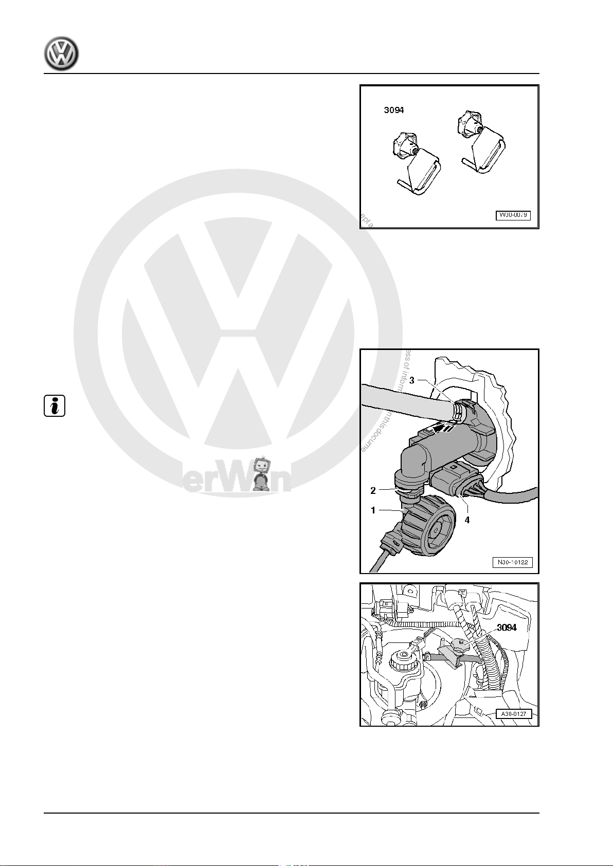
P
r
o
t
e
c
t
e
d
b
y
c
o
p
y
r
i
g
h
t
.
C
o
p
y
i
n
g
f
o
r
p
r
i
v
a
t
e
o
r
c
o
m
m
e
r
c
i
a
l
p
u
r
p
o
s
e
s
,
i
n
p
a
r
t
o
r
i
n
w
h
o
l
e
,
i
s
n
o
t
p
e
r
m
i
t
t
e
d
u
n
l
e
s
s
a
u
t
h
o
r
i
s
e
d
b
y
V
o
l
k
s
w
a
g
e
n
A
G
.
V
o
l
k
s
w
a
g
e
n
A
G
d
o
e
s
n
o
t
g
u
a
r
a
n
t
e
e
o
r
a
c
c
e
p
t
a
n
y
l
i
a
b
i
l
i
t
y
w
i
t
h
r
e
s
p
e
c
t
t
o
t
h
e
c
o
r
r
e
c
t
n
e
s
s
o
f
i
n
f
o
r
m
a
t
i
o
n
i
n
t
h
i
s
d
o
c
u
m
e
n
t
.
C
o
p
y
r
i
g
h
t
b
y
V
o
l
k
s
w
a
g
e
n
A
G
.
Jetta 2006 ➤ , Golf Variant 2008 ➤
5-speed manual gearbox 0AF - Edition 08.2007
♦ Hose clamps -3094-
Note
2.7.1 Removing
– First check whether a coded radio is fitted. If so, obtain anti-
theft code.
– Remove complete air filter housing if it is near battery ⇒ Rep.
Gr. 24 ; Repairing injection system .
– Remove battery, battery cover and battery tray ⇒ Electrical
system; Rep. Gr. 27 ; Removing and installing battery .
If a pipe/hose line or plastic line -1- with a round component is
installed directly beneath the master cylinder, the pipe/hose line
or plastic line must be removed.
♦
During the following work, ensure that no brake fluid lands on
longitudinal member or gearbox. If this does happen, clean the
affected areas thoroughly.
♦
Place a lint-free cloth under the master cylinder.
– Clamp off supply hose to master cylinder using hose clamp
-3094- .
22 Rep. Gr.30 - Clutch
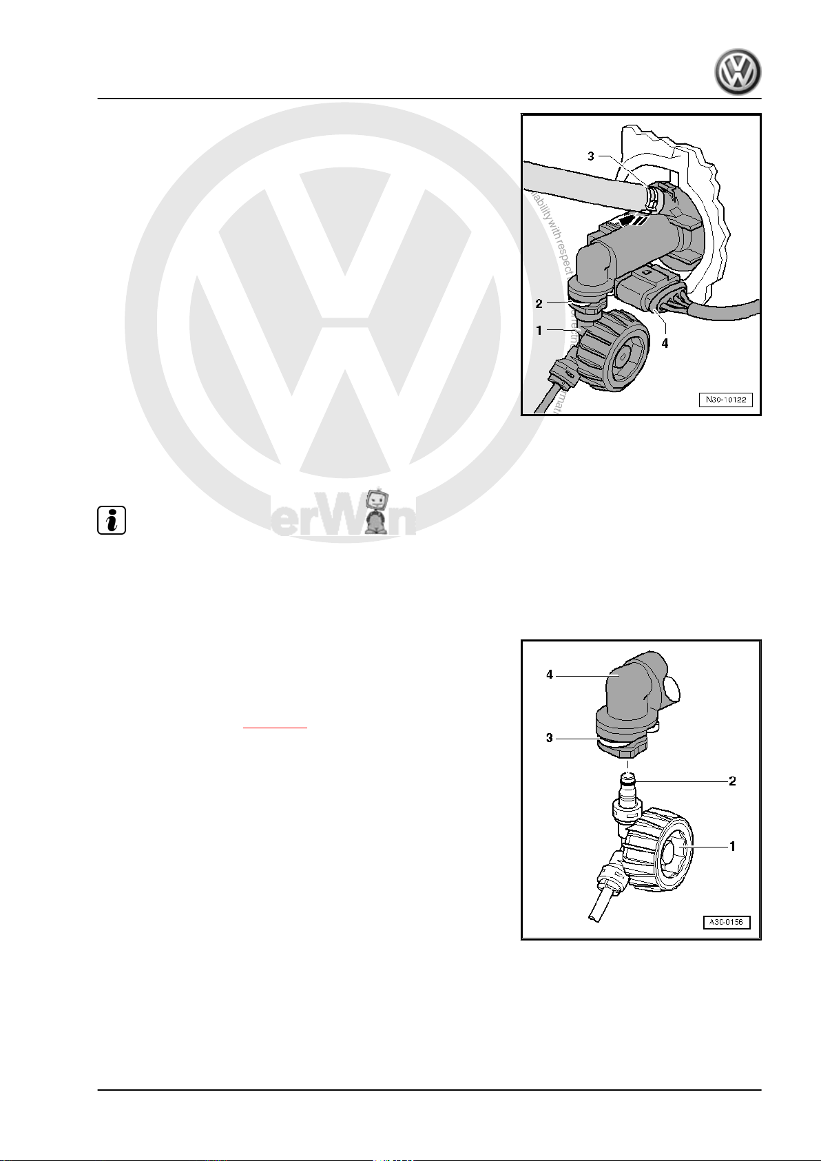
P
r
o
t
e
c
t
e
d
b
y
c
o
p
y
r
i
g
h
t
.
C
o
p
y
i
n
g
f
o
r
p
r
i
v
a
t
e
o
r
c
o
m
m
e
r
c
i
a
l
p
u
r
p
o
s
e
s
,
i
n
p
a
r
t
o
r
i
n
w
h
o
l
e
,
i
s
n
o
t
p
e
r
m
i
t
t
e
d
u
n
l
e
s
s
a
u
t
h
o
r
i
s
e
d
b
y
V
o
l
k
s
w
a
g
e
n
A
G
.
V
o
l
k
s
w
a
g
e
n
A
G
d
o
e
s
n
o
t
g
u
a
r
a
n
t
e
e
o
r
a
c
c
e
p
t
a
n
y
l
i
a
b
i
l
i
t
y
w
i
t
h
r
e
s
p
e
c
t
t
o
t
h
e
c
o
r
r
e
c
t
n
e
s
s
o
f
i
n
f
o
r
m
a
t
i
o
n
i
n
t
h
i
s
d
o
c
u
m
e
n
t
.
C
o
p
y
r
i
g
h
t
b
y
V
o
l
k
s
w
a
g
e
n
A
G
.
– Release securing clip -2- with a screwdriver and pull out of
master cylinder to stop.
– Pull pipe/hose line or plastic line -1- out from master cylinder
and seal hose.
All vehicles
– Disconnect electrical connector -4-.
– Unclip clutch position sender -G476- from master cylinder
-arrow- and remove.
2.7.2 Installing
Install in reverse order of removal. During this step, observe the
following:
Note
♦
Renew hose clips.
♦
Allocate all components according to ⇒ Electronic parts cata‐
5-speed manual gearbox 0AF - Edition 08.2007
logue “ETKA” .
Jetta 2006 ➤ , Golf Variant 2008 ➤
If the pipe/hose line or plastic line was removed:
– Push pipe/hose line or plastic line -1- with seal -2- onto con‐
nection of master cylinder -4- until securing clip -3- engages
audibly.
– Test line by tugging on it.
– Bleed clutch system ⇒ page 27 .
All vehicles
– Install battery tray and battery⇒ Electrical system; Rep. Gr.
27 ; Removing and installing battery .
– If removed, install complete air filter housing ⇒ Rep. Gr. 24 ;
Repairing injection system .
– Reconnect battery and perform work required after connecting
battery ⇒ Electrical system; Rep. Gr. 27 ; Disconnecting and
connecting battery .
2. Repairing clutch mechanism 23
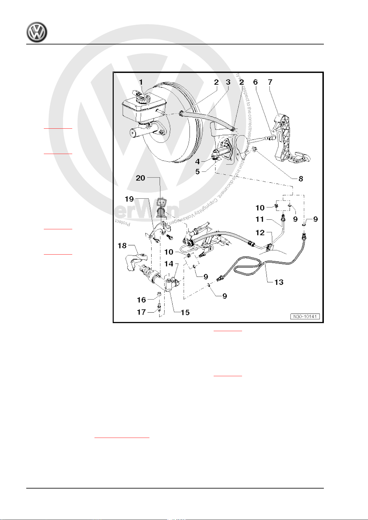
P
r
o
t
e
c
t
e
d
b
y
c
o
p
y
r
i
g
h
t
.
C
o
p
y
i
n
g
f
o
r
p
r
i
v
a
t
e
o
r
c
o
m
m
e
r
c
i
a
l
p
u
r
p
o
s
e
s
,
i
n
p
a
r
t
o
r
i
n
w
h
o
l
e
,
i
s
n
o
t
p
e
r
m
i
t
t
e
d
u
n
l
e
s
s
a
u
t
h
o
r
i
s
e
d
b
y
V
o
l
k
s
w
a
g
e
n
A
G
.
V
o
l
k
s
w
a
g
e
n
A
G
d
o
e
s
n
o
t
g
u
a
r
a
n
t
e
e
o
r
a
c
c
e
p
t
a
n
y
l
i
a
b
i
l
i
t
y
w
i
t
h
r
e
s
p
e
c
t
t
o
t
h
e
c
o
r
r
e
c
t
n
e
s
s
o
f
i
n
f
o
r
m
a
t
i
o
n
i
n
t
h
i
s
d
o
c
u
m
e
n
t
.
C
o
p
y
r
i
g
h
t
b
y
V
o
l
k
s
w
a
g
e
n
A
G
.
Jetta 2006 ➤ , Golf Variant 2008 ➤
5-speed manual gearbox 0AF - Edition 08.2007
2.8 Assembly overview - hydraulic system
1 - Brake fluid reservoir
2 - Spring-type clip
3 - Supply hose
❑ Rubber
❑ From 12.05, plastic in
4 - Master cylinder
❑ Removing and installing
5 - Clip
❑ Pull clip out to stop to re‐
6 - Retainer
❑ To remove and install,
some vehicles
⇒ page 25
⇒ page 19
move or install line be‐
tween master and slave
cylinders
separate master cylin‐
der from clutch pedal.
⇒ page 14
7 - Clutch pedal
❑ Removing and installing
⇒ page 14
8 - Self-locking hexagon nut,
25 Nm
❑ Mounting bracket to
body
❑ Always renew
9 - O-ring
❑ Pull onto line connection
❑ Insert with brake fluid
❑ Seals, O-rings depending on configuration of line connections ⇒ page 25
❑ Allocation ⇒ Electronic parts catalogue “ETKA”
10 - Seal
❑ Pull onto line connection
❑ Insert with brake fluid
❑ Seals, O-rings depending on configuration of line connections ⇒ page 25
❑ Allocation ⇒ Electronic parts catalogue “ETKA”
11 - Pipe/hose line
❑ Allocation ⇒ Electronic parts catalogue “ETKA”
❑ To remove, remove battery and battery tray ⇒ Electrical system; Rep. Gr. 27 ; Removing and installing
battery .
12 - Retainer
❑ For pipe/hose line ⇒ Item 11 (page 24)
❑ Secured to body.
13 - Plastic line
❑ Allocation ⇒ Electronic parts catalogue “ETKA”
❑ To remove, remove battery and battery tray ⇒ Electrical system; Rep. Gr. 27 ; Removing and installing
battery .
24 Rep. Gr.30 - Clutch
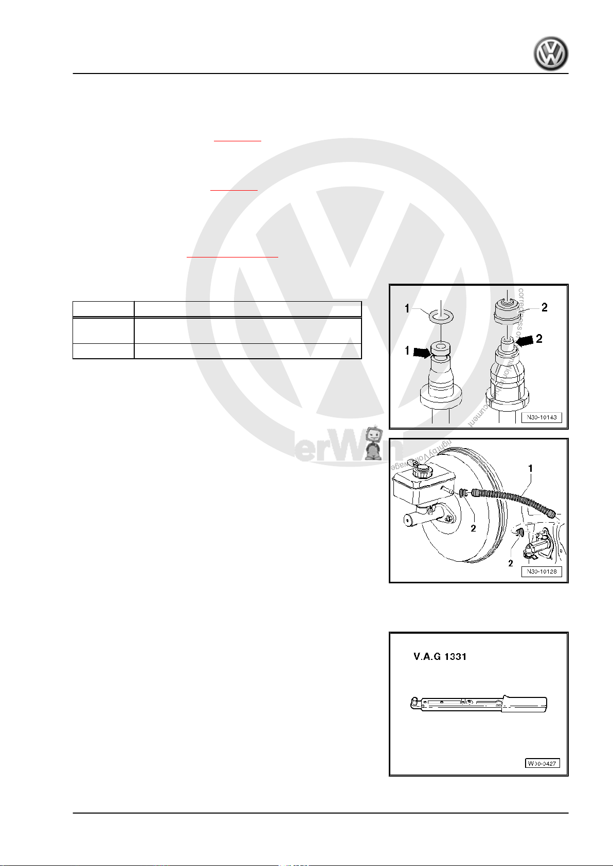
P
r
o
t
e
c
t
e
d
b
y
c
o
p
y
r
i
g
h
t
.
C
o
p
y
i
n
g
f
o
r
p
r
i
v
a
t
e
o
r
c
o
m
m
e
r
c
i
a
l
p
u
r
p
o
s
e
s
,
i
n
p
a
r
t
o
r
i
n
w
h
o
l
e
,
i
s
n
o
t
p
e
r
m
i
t
t
e
d
u
n
l
e
s
s
a
u
t
h
o
r
i
s
e
d
b
y
V
o
l
k
s
w
a
g
e
n
A
G
.
V
o
l
k
s
w
a
g
e
n
A
G
d
o
e
s
n
o
t
g
u
a
r
a
n
t
e
e
o
r
a
c
c
e
p
t
a
n
y
l
i
a
b
i
l
i
t
y
w
i
t
h
r
e
s
p
e
c
t
t
o
t
h
e
c
o
r
r
e
c
t
n
e
s
s
o
f
i
n
f
o
r
m
a
t
i
o
n
i
n
t
h
i
s
d
o
c
u
m
e
n
t
.
C
o
p
y
r
i
g
h
t
b
y
V
o
l
k
s
w
a
g
e
n
A
G
.
Jetta 2006 ➤ , Golf Variant 2008 ➤
5-speed manual gearbox 0AF - Edition 08.2007
14 - Clip
❑ Pull clip out to stop to remove or install line between master and slave cylinders
15 - Slave cylinder
❑ Removing and installing ⇒ page 25
16 - Dust cap
17 - Bleeder valve
❑ Bleeding clutch system ⇒ page 27
18 - Gearbox
19 - Hexagon bolt, 20 Nm
20 - Retainer
❑ For pipe/hose line ⇒ Item 11 (page 24)
Seals and O-rings for pipe/hose line or plastic line
Item Version of line connection
-1- Line connection with circumferential groove
-2- Line connection with shoulder -arrow 2-
-arrow 1-
From 12.05, plastic supply hose -1- in some vehicles.
• The seals -2- must be located in supply hose.
2.9 Removing and installing slave cylinder
Special tools and workshop equipment required
♦ Torque wrench -V.A.G 1331-
2. Repairing clutch mechanism 25
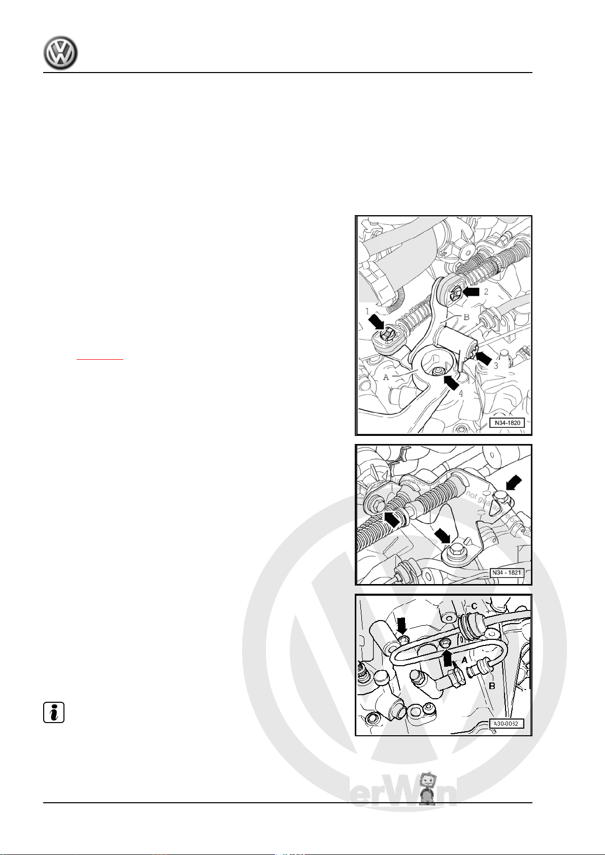
P
r
o
t
e
c
t
e
d
b
y
c
o
p
y
r
i
g
h
t
.
C
o
p
y
i
n
g
f
o
r
p
r
i
v
a
t
e
o
r
c
o
m
m
e
r
c
i
a
l
p
u
r
p
o
s
e
s
,
i
n
p
a
r
t
o
r
i
n
w
h
o
l
e
,
i
s
n
o
t
p
e
r
m
i
t
t
e
d
u
n
l
e
s
s
a
u
t
h
o
r
i
s
e
d
b
y
V
o
l
k
s
w
a
g
e
n
A
G
.
V
o
l
k
s
w
a
g
e
n
A
G
d
o
e
s
n
o
t
g
u
a
r
a
n
t
e
e
o
r
a
c
c
e
p
t
a
n
y
l
i
a
b
i
l
i
t
y
w
i
t
h
r
e
s
p
e
c
t
t
o
t
h
e
c
o
r
r
e
c
t
n
e
s
s
o
f
i
n
f
o
r
m
a
t
i
o
n
i
n
t
h
i
s
d
o
c
u
m
e
n
t
.
C
o
p
y
r
i
g
h
t
b
y
V
o
l
k
s
w
a
g
e
n
A
G
.
Jetta 2006 ➤ , Golf Variant 2008 ➤
5-speed manual gearbox 0AF - Edition 08.2007
2.9.1 Removing
– First check whether a coded radio is fitted. If so, obtain anti-
theft code.
– With ignition switched off, disconnect battery ⇒ Electrical sys‐
tem; Rep. Gr. 27 ; Disconnecting and connecting battery .
– Remove complete air filter housing if it is near slave cylinder
⇒ Rep. Gr. 24 ; Repairing injection system .
– Remove securing clip for gear selector cable -arrow 1- from
gearbox selector lever -A-.
– Pull gear selector cable from pin.
Metal relay lever
– Remove securing clip -arrow 2- for gate selector cable from
relay lever -B-.
– Pull gate selector cable from pin.
– Pull securing clip -arrow 3- off relay lever -B- and remove relay
lever.
Plastic relay lever
– Remove relay lever together with cable end-piece from gear‐
box ⇒ page 50 .
Continuation for all
– Remove gearbox selector lever -A- by removing nut
-arrow 4-.
– Remove cable support bracket from gearbox -arrows-.
– Then tie up selector cable and gate cable.
– Place a lint-free cloth under slave cylinder.
– Pull clip -A- for line between master and slave cylinders out of
slave cylinder to stop.
– Pull line between master and slave cylinders out of support
-C-.
– Pull line between master and slave cylinders -B- out of slave
cylinder and seal opening.
– Unbolt slave cylinder -arrows- and remove.
Note
Do not depress clutch pedal.
26 Rep. Gr.30 - Clutch

P
r
o
t
e
c
t
e
d
b
y
c
o
p
y
r
i
g
h
t
.
C
o
p
y
i
n
g
f
o
r
p
r
i
v
a
t
e
o
r
c
o
m
m
e
r
c
i
a
l
p
u
r
p
o
s
e
s
,
i
n
p
a
r
t
o
r
i
n
w
h
o
l
e
,
i
s
n
o
t
p
e
r
m
i
t
t
e
d
u
n
l
e
s
s
a
u
t
h
o
r
i
s
e
d
b
y
V
o
l
k
s
w
a
g
e
n
A
G
.
V
o
l
k
s
w
a
g
e
n
A
G
d
o
e
s
n
o
t
g
u
a
r
a
n
t
e
e
o
r
a
c
c
e
p
t
a
n
y
l
i
a
b
i
l
i
t
y
w
i
t
h
r
e
s
p
e
c
t
t
o
t
h
e
c
o
r
r
e
c
t
n
e
s
s
o
f
i
n
f
o
r
m
a
t
i
o
n
i
n
t
h
i
s
d
o
c
u
m
e
n
t
.
C
o
p
y
r
i
g
h
t
b
y
V
o
l
k
s
w
a
g
e
n
A
G
.
2.9.2 Installing
Carry out installation in the reverse sequence, noting the follow‐
ing:
– Install slave cylinder and tighten bolts -arrows- to specified
torque ⇒ Item 19 (page 25) .
– Insert line between master and slave cylinders -B- into slave
cylinder to stop.
– Push securing clip -A- into line between master and slave cyl‐
inders to stop.
– Test pipe/hose line by tugging on it.
– Press line between master and slave cylinders into mounting
-C- to stop on gearbox.
– Bleed clutch system after installing slave cylinder
⇒ page 27 .
Assembling selector mechanism ⇒ page 47 .
Adjusting selector mechanism ⇒ page 54 .
– If removed, install complete air filter housing ⇒ Rep. Gr. 24 ;
Repairing injection system .
– Connect battery earth ⇒ Electrical system; Rep. Gr. 27 ; Bat‐
tery; Disconnecting and connecting battery .
5-speed manual gearbox 0AF - Edition 08.2007
2.10 Bleeding clutch system
Jetta 2006 ➤ , Golf Variant 2008 ➤
Special tools and workshop equipment required
♦ Brake filling and bleeding equipment -VAS 5234- or
♦ Brake filling and bleeding equipment -V.A.G 1869-
2. Repairing clutch mechanism 27

P
r
o
t
e
c
t
e
d
b
y
c
o
p
y
r
i
g
h
t
.
C
o
p
y
i
n
g
f
o
r
p
r
i
v
a
t
e
o
r
c
o
m
m
e
r
c
i
a
l
p
u
r
p
o
s
e
s
,
i
n
p
a
r
t
o
r
i
n
w
h
o
l
e
,
i
s
n
o
t
p
e
r
m
i
t
t
e
d
u
n
l
e
s
s
a
u
t
h
o
r
i
s
e
d
b
y
V
o
l
k
s
w
a
g
e
n
A
G
.
V
o
l
k
s
w
a
g
e
n
A
G
d
o
e
s
n
o
t
g
u
a
r
a
n
t
e
e
o
r
a
c
c
e
p
t
a
n
y
l
i
a
b
i
l
i
t
y
w
i
t
h
r
e
s
p
e
c
t
t
o
t
h
e
c
o
r
r
e
c
t
n
e
s
s
o
f
i
n
f
o
r
m
a
t
i
o
n
i
n
t
h
i
s
d
o
c
u
m
e
n
t
.
C
o
p
y
r
i
g
h
t
b
y
V
o
l
k
s
w
a
g
e
n
A
G
.
Jetta 2006 ➤ , Golf Variant 2008 ➤
5-speed manual gearbox 0AF - Edition 08.2007
Note
Prefilling system is not necessary!
Specifications for brake fluid ⇒ Brake systems; Rep. Gr. 47 ;
Bleeding brake system .
– Remove complete air filter housing if it hinders access to slave
cylinder ⇒ Rep. Gr. 24 ; Repairing injection system .
– Connect brake filling and bleeding equipment -VAS 5234- or
-V.A.G 1869- .
To bleed system, use 670 mm bleeder hose -V.A.G 1238/B3- if
necessary.
– Connect bleeder hose to collector bottle of brake bleeding
equipment.
– Connect bleed hose to bleeder -arrow-.
– Pressurise system to 2 bar.
– Open bleeder valve.
–
Bleed off about 100 cm3 brake fluid.
– Close bleeder valve.
– Rapidly operate pedal from stop to stop 10 to 15 times.
– Open bleeder valve.
–
Bleed off an additional 50 cm3 brake fluid.
– Close bleeder valve.
– Depress clutch pedal several times after completion of bleed‐
ing process.
– Install, if necessary, complete air filter housing ⇒ Rep. Gr.
24 ; Repairing injection system .
28 Rep. Gr.30 - Clutch

P
r
o
t
e
c
t
e
d
b
y
c
o
p
y
r
i
g
h
t
.
C
o
p
y
i
n
g
f
o
r
p
r
i
v
a
t
e
o
r
c
o
m
m
e
r
c
i
a
l
p
u
r
p
o
s
e
s
,
i
n
p
a
r
t
o
r
i
n
w
h
o
l
e
,
i
s
n
o
t
p
e
r
m
i
t
t
e
d
u
n
l
e
s
s
a
u
t
h
o
r
i
s
e
d
b
y
V
o
l
k
s
w
a
g
e
n
A
G
.
V
o
l
k
s
w
a
g
e
n
A
G
d
o
e
s
n
o
t
g
u
a
r
a
n
t
e
e
o
r
a
c
c
e
p
t
a
n
y
l
i
a
b
i
l
i
t
y
w
i
t
h
r
e
s
p
e
c
t
t
o
t
h
e
c
o
r
r
e
c
t
n
e
s
s
o
f
i
n
f
o
r
m
a
t
i
o
n
i
n
t
h
i
s
d
o
c
u
m
e
n
t
.
C
o
p
y
r
i
g
h
t
b
y
V
o
l
k
s
w
a
g
e
n
A
G
.
5-speed manual gearbox 0AF - Edition 08.2007
3 Repairing clutch release mechanism
Special tools and workshop equipment required
♦ Torque wrench -V.A.G 1331-
1 - Release bearing
❑ Remove and install to‐
gether with clutch re‐
lease lever
⇒ Item 3 (page 29)
and guide sleeve
⇒ Item 5 (page 29)
⇒ page 30 to
⇒ page 30
❑ Do not wash out bear‐
ing; wipe only
❑ Renew noisy bearings
2 - Bolt, 5 Nm then turn 90° fur‐
ther
❑ Always renew
3 - Clutch release lever
❑ Remove and install to‐
gether with release
bearing
⇒ Item 1 (page 29) and
guide sleeve
⇒ Item 5 (page 29)
⇒ page 30 to
⇒ page 30
❑ Remove old grease
4 - Retaining spring
❑ Secure to clutch release
lever
5 - Guide sleeve
❑ Remove and install to‐
gether with release
bearing
⇒ Item 1 (page 29) and
guide sleeve
⇒ Item 5 (page 29)
⇒ page 30 to ⇒ page 30
6 - Input shaft seal
❑ Removing and installing ⇒ page 89
Jetta 2006 ➤ , Golf Variant 2008 ➤
7 - Ball stud, 20 Nm
❑ Remove old grease
3. Repairing clutch release mechanism 29

P
r
o
t
e
c
t
e
d
b
y
c
o
p
y
r
i
g
h
t
.
C
o
p
y
i
n
g
f
o
r
p
r
i
v
a
t
e
o
r
c
o
m
m
e
r
c
i
a
l
p
u
r
p
o
s
e
s
,
i
n
p
a
r
t
o
r
i
n
w
h
o
l
e
,
i
s
n
o
t
p
e
r
m
i
t
t
e
d
u
n
l
e
s
s
a
u
t
h
o
r
i
s
e
d
b
y
V
o
l
k
s
w
a
g
e
n
A
G
.
V
o
l
k
s
w
a
g
e
n
A
G
d
o
e
s
n
o
t
g
u
a
r
a
n
t
e
e
o
r
a
c
c
e
p
t
a
n
y
l
i
a
b
i
l
i
t
y
w
i
t
h
r
e
s
p
e
c
t
t
o
t
h
e
c
o
r
r
e
c
t
n
e
s
s
o
f
i
n
f
o
r
m
a
t
i
o
n
i
n
t
h
i
s
d
o
c
u
m
e
n
t
.
C
o
p
y
r
i
g
h
t
b
y
V
o
l
k
s
w
a
g
e
n
A
G
.
Jetta 2006 ➤ , Golf Variant 2008 ➤
5-speed manual gearbox 0AF - Edition 08.2007
❑ Lubricate with grease -G 000 100-
8 - Gearbox
9 - Hexagon bolt, 20 Nm
10 - Retainer
❑ For pipe/hose line ⇒ Item 11 (page 24)
11 - Slave cylinder
❑ Removing and installing ⇒ page 25
Removing and installing clutch release lever with release bearing
and guide sleeve
– Remove bolts -arrows-.
– Pull clutch release lever with release bearing and guide sleeve
off input shaft and ball stud.
Install in reverse order of removal.
Removing and installing guide sleeve
– Push guide sleeve -3- upwards out of release bearing -2-.
– Turn guide sleeve -3- about 90° in direction of arrow relative
to release bearing -2- until locking lugs of guide sleeve align
with grooves -4- of release bearing.
– Pull guide sleeve out of release bearing in this position.
Install in reverse order of removal.
Removing and installing release bearing
– Press together locking lugs -arrows- on back of clutch release
lever and remove release bearing -A- from clutch release lev‐
er.
– To install, press release bearing -A- into clutch release lever
until locking lugs -arrows- engage.
30 Rep. Gr.30 - Clutch

P
r
o
t
e
c
t
e
d
b
y
c
o
p
y
r
i
g
h
t
.
C
o
p
y
i
n
g
f
o
r
p
r
i
v
a
t
e
o
r
c
o
m
m
e
r
c
i
a
l
p
u
r
p
o
s
e
s
,
i
n
p
a
r
t
o
r
i
n
w
h
o
l
e
,
i
s
n
o
t
p
e
r
m
i
t
t
e
d
u
n
l
e
s
s
a
u
t
h
o
r
i
s
e
d
b
y
V
o
l
k
s
w
a
g
e
n
A
G
.
V
o
l
k
s
w
a
g
e
n
A
G
d
o
e
s
n
o
t
g
u
a
r
a
n
t
e
e
o
r
a
c
c
e
p
t
a
n
y
l
i
a
b
i
l
i
t
y
w
i
t
h
r
e
s
p
e
c
t
t
o
t
h
e
c
o
r
r
e
c
t
n
e
s
s
o
f
i
n
f
o
r
m
a
t
i
o
n
i
n
t
h
i
s
d
o
c
u
m
e
n
t
.
C
o
p
y
r
i
g
h
t
b
y
V
o
l
k
s
w
a
g
e
n
A
G
.
4 Repairing clutch
Special tools and workshop
equipment required
♦ Counterhold -3067-
♦ Torque wrench -V.A.G
1331-
♦ Centring mandrel -3190 A-
♦ Grease for clutch plate
splines -G 000 100-
(Gearbox removed)
Note
Jetta 2006 ➤ , Golf Variant 2008 ➤
5-speed manual gearbox 0AF - Edition 08.2007
♦
Check whether dowel sleeves for aligning engine and gearbox are fitted in cylinder block and install if nec‐
essary.
♦
If dowel sleeves are not fitted, difficulties shifting gears, clutch problems and possible noises from the gear‐
box (rattling of gears which are not engaged) could occur.
♦
Replace clutch plates and pressure plates with damaged or loose rivets.
♦
Allocation ⇒ Electronic parts catalogue “ETKA” .
4. Repairing clutch 31

P
r
o
t
e
c
t
e
d
b
y
c
o
p
y
r
i
g
h
t
.
C
o
p
y
i
n
g
f
o
r
p
r
i
v
a
t
e
o
r
c
o
m
m
e
r
c
i
a
l
p
u
r
p
o
s
e
s
,
i
n
p
a
r
t
o
r
i
n
w
h
o
l
e
,
i
s
n
o
t
p
e
r
m
i
t
t
e
d
u
n
l
e
s
s
a
u
t
h
o
r
i
s
e
d
b
y
V
o
l
k
s
w
a
g
e
n
A
G
.
V
o
l
k
s
w
a
g
e
n
A
G
d
o
e
s
n
o
t
g
u
a
r
a
n
t
e
e
o
r
a
c
c
e
p
t
a
n
y
l
i
a
b
i
l
i
t
y
w
i
t
h
r
e
s
p
e
c
t
t
o
t
h
e
c
o
r
r
e
c
t
n
e
s
s
o
f
i
n
f
o
r
m
a
t
i
o
n
i
n
t
h
i
s
d
o
c
u
m
e
n
t
.
C
o
p
y
r
i
g
h
t
b
y
V
o
l
k
s
w
a
g
e
n
A
G
.
Jetta 2006 ➤ , Golf Variant 2008 ➤
5-speed manual gearbox 0AF - Edition 08.2007
1 - Flywheel
❑ Ensure that centring
pins fit tightly
❑ Contact surface for
clutch lining must be
free of grooves, oil and
grease
❑ Removing and installing
⇒ Rep. Gr. 13
2 - Clutch plate
❑ Allocation ⇒ Electronic
parts catalogue “ETKA”
❑ Installation position with
two-part flywheel: short‐
er end of hub faces
pressure plate
❑ Text
“Getriebeseite” (gear‐
box side) always faces
pressure plate and
gearbox
❑ Installation position with
single piece flywheel:
spring cage faces pres‐
sure plate
❑ Centring ⇒ page 32 .
❑ Lightly grease splines
Note
3 - Pressure plate
❑ Removing and installing
⇒ page 32 .
❑ Check ends of dia‐
phragm spring
⇒ page 33
Note
4 - Bolt, 20 Nm
❑ Allocation ⇒ Electronic parts catalogue “ETKA”
❑ Loosen or tighten diagonally and in steps
Centring clutch plate and removing and installing pressure plate
– Loosen or tighten bolts diagonally in stages.
– Reverse position of counterhold -3067- when removing.
Note
Pressure plate contact surface and clutch plate lining must make
full contact with flywheel. Tighten securing bolts diagonally and
evenly to prevent damage to the pressure plate centring hole and
the flywheel centring pins.
32 Rep. Gr.30 - Clutch

P
r
o
t
e
c
t
e
d
b
y
c
o
p
y
r
i
g
h
t
.
C
o
p
y
i
n
g
f
o
r
p
r
i
v
a
t
e
o
r
c
o
m
m
e
r
c
i
a
l
p
u
r
p
o
s
e
s
,
i
n
p
a
r
t
o
r
i
n
w
h
o
l
e
,
i
s
n
o
t
p
e
r
m
i
t
t
e
d
u
n
l
e
s
s
a
u
t
h
o
r
i
s
e
d
b
y
V
o
l
k
s
w
a
g
e
n
A
G
.
V
o
l
k
s
w
a
g
e
n
A
G
d
o
e
s
n
o
t
g
u
a
r
a
n
t
e
e
o
r
a
c
c
e
p
t
a
n
y
l
i
a
b
i
l
i
t
y
w
i
t
h
r
e
s
p
e
c
t
t
o
t
h
e
c
o
r
r
e
c
t
n
e
s
s
o
f
i
n
f
o
r
m
a
t
i
o
n
i
n
t
h
i
s
d
o
c
u
m
e
n
t
.
C
o
p
y
r
i
g
h
t
b
y
V
o
l
k
s
w
a
g
e
n
A
G
.
Checking ends of diaphragm spring -arrows-
• Wear up to half the thickness of the diaphragm spring is per‐
mitted.
5-speed manual gearbox 0AF - Edition 08.2007
Jetta 2006 ➤ , Golf Variant 2008 ➤
4. Repairing clutch 33

P
r
o
t
e
c
t
e
d
b
y
c
o
p
y
r
i
g
h
t
.
C
o
p
y
i
n
g
f
o
r
p
r
i
v
a
t
e
o
r
c
o
m
m
e
r
c
i
a
l
p
u
r
p
o
s
e
s
,
i
n
p
a
r
t
o
r
i
n
w
h
o
l
e
,
i
s
n
o
t
p
e
r
m
i
t
t
e
d
u
n
l
e
s
s
a
u
t
h
o
r
i
s
e
d
b
y
V
o
l
k
s
w
a
g
e
n
A
G
.
V
o
l
k
s
w
a
g
e
n
A
G
d
o
e
s
n
o
t
g
u
a
r
a
n
t
e
e
o
r
a
c
c
e
p
t
a
n
y
l
i
a
b
i
l
i
t
y
w
i
t
h
r
e
s
p
e
c
t
t
o
t
h
e
c
o
r
r
e
c
t
n
e
s
s
o
f
i
n
f
o
r
m
a
t
i
o
n
i
n
t
h
i
s
d
o
c
u
m
e
n
t
.
C
o
p
y
r
i
g
h
t
b
y
V
o
l
k
s
w
a
g
e
n
A
G
.
Jetta 2006 ➤ , Golf Variant 2008 ➤
5-speed manual gearbox 0AF - Edition 08.2007
34 – Controls, housing
1 Fault finding, Power transmission
– Refer to ⇒ Fault finding, power transmission; Rep. Gr. 30 ;
Complaints about clutch and clutch mechanism and ⇒ Fault
finding, power transmission; Rep. Gr. 34 ; Complaints about
selector mechanism
34 Rep. Gr.34 - Controls, housing

P
r
o
t
e
c
t
e
d
b
y
c
o
p
y
r
i
g
h
t
.
C
o
p
y
i
n
g
f
o
r
p
r
i
v
a
t
e
o
r
c
o
m
m
e
r
c
i
a
l
p
u
r
p
o
s
e
s
,
i
n
p
a
r
t
o
r
i
n
w
h
o
l
e
,
i
s
n
o
t
p
e
r
m
i
t
t
e
d
u
n
l
e
s
s
a
u
t
h
o
r
i
s
e
d
b
y
V
o
l
k
s
w
a
g
e
n
A
G
.
V
o
l
k
s
w
a
g
e
n
A
G
d
o
e
s
n
o
t
g
u
a
r
a
n
t
e
e
o
r
a
c
c
e
p
t
a
n
y
l
i
a
b
i
l
i
t
y
w
i
t
h
r
e
s
p
e
c
t
t
o
t
h
e
c
o
r
r
e
c
t
n
e
s
s
o
f
i
n
f
o
r
m
a
t
i
o
n
i
n
t
h
i
s
d
o
c
u
m
e
n
t
.
C
o
p
y
r
i
g
h
t
b
y
V
o
l
k
s
w
a
g
e
n
A
G
.
2 Repairing selector mechanism
2.1 Installation position of selector mechanism
Arrow -A- Gear selection movement
Arrow -B- Gate selection movement
A - Gear selector cable
B - Gate selector cable
C - Heat shield
❑ Remove before remov‐
ing gear selector mech‐
anism
1 - Gearbox selector lever
2 - Relay lever
5-speed manual gearbox 0AF - Edition 08.2007
Jetta 2006 ➤ , Golf Variant 2008 ➤
2. Repairing selector mechanism 35

P
r
o
t
e
c
t
e
d
b
y
c
o
p
y
r
i
g
h
t
.
C
o
p
y
i
n
g
f
o
r
p
r
i
v
a
t
e
o
r
c
o
m
m
e
r
c
i
a
l
p
u
r
p
o
s
e
s
,
i
n
p
a
r
t
o
r
i
n
w
h
o
l
e
,
i
s
n
o
t
p
e
r
m
i
t
t
e
d
u
n
l
e
s
s
a
u
t
h
o
r
i
s
e
d
b
y
V
o
l
k
s
w
a
g
e
n
A
G
.
V
o
l
k
s
w
a
g
e
n
A
G
d
o
e
s
n
o
t
g
u
a
r
a
n
t
e
e
o
r
a
c
c
e
p
t
a
n
y
l
i
a
b
i
l
i
t
y
w
i
t
h
r
e
s
p
e
c
t
t
o
t
h
e
c
o
r
r
e
c
t
n
e
s
s
o
f
i
n
f
o
r
m
a
t
i
o
n
i
n
t
h
i
s
d
o
c
u
m
e
n
t
.
C
o
p
y
r
i
g
h
t
b
y
V
o
l
k
s
w
a
g
e
n
A
G
.
Jetta 2006 ➤ , Golf Variant 2008 ➤
5-speed manual gearbox 0AF - Edition 08.2007
Note
♦
Note radio code for vehicles with coded radio.
♦
Before working on the selector mechanism, disconnect earth strap from the battery in the engine compart‐
ment.
♦
⇒ Electrical system; Rep. Gr. 27 ; Disconnecting and connecting battery
♦
When reconnecting battery, perform work required after connecting battery ⇒ Electrical system; Rep. Gr.
27 ; Disconnecting and connecting battery .
♦
For work on selector mechanism in engine compartment, remove complete air filter housing if it is located
over selector mechanism ⇒ Rep. Gr. 24 .
♦
Remove selector mechanism to renew selector cables ⇒ page 51 .
♦
Do not kink selector cables.
I - Removing and installing se‐
lector lever knob and cover
⇒ page 38
II - Repairing selector lever and
selector lever housing
(through 10.06) ⇒ page 40
II - Repairing selector lever and
selector lever housing (from
11.06) ⇒ page 42
III - Assembly overview - re‐
moving and installing selector
cables ⇒ page 47
Removing and installing selector mechanism ⇒ page 51
Adjusting selector mechanism ⇒ page 54 .
Special tools and workshop equipment required
36 Rep. Gr.34 - Controls, housing

P
r
o
t
e
c
t
e
d
b
y
c
o
p
y
r
i
g
h
t
.
C
o
p
y
i
n
g
f
o
r
p
r
i
v
a
t
e
o
r
c
o
m
m
e
r
c
i
a
l
p
u
r
p
o
s
e
s
,
i
n
p
a
r
t
o
r
i
n
w
h
o
l
e
,
i
s
n
o
t
p
e
r
m
i
t
t
e
d
u
n
l
e
s
s
a
u
t
h
o
r
i
s
e
d
b
y
V
o
l
k
s
w
a
g
e
n
A
G
.
V
o
l
k
s
w
a
g
e
n
A
G
d
o
e
s
n
o
t
g
u
a
r
a
n
t
e
e
o
r
a
c
c
e
p
t
a
n
y
l
i
a
b
i
l
i
t
y
w
i
t
h
r
e
s
p
e
c
t
t
o
t
h
e
c
o
r
r
e
c
t
n
e
s
s
o
f
i
n
f
o
r
m
a
t
i
o
n
i
n
t
h
i
s
d
o
c
u
m
e
n
t
.
C
o
p
y
r
i
g
h
t
b
y
V
o
l
k
s
w
a
g
e
n
A
G
.
♦ Hose clip pliers -V.A.G 1275-
♦ Torque wrench -V.A.G 1331-
Jetta 2006 ➤ , Golf Variant 2008 ➤
5-speed manual gearbox 0AF - Edition 08.2007
2. Repairing selector mechanism 37

P
r
o
t
e
c
t
e
d
b
y
c
o
p
y
r
i
g
h
t
.
C
o
p
y
i
n
g
f
o
r
p
r
i
v
a
t
e
o
r
c
o
m
m
e
r
c
i
a
l
p
u
r
p
o
s
e
s
,
i
n
p
a
r
t
o
r
i
n
w
h
o
l
e
,
i
s
n
o
t
p
e
r
m
i
t
t
e
d
u
n
l
e
s
s
a
u
t
h
o
r
i
s
e
d
b
y
V
o
l
k
s
w
a
g
e
n
A
G
.
V
o
l
k
s
w
a
g
e
n
A
G
d
o
e
s
n
o
t
g
u
a
r
a
n
t
e
e
o
r
a
c
c
e
p
t
a
n
y
l
i
a
b
i
l
i
t
y
w
i
t
h
r
e
s
p
e
c
t
t
o
t
h
e
c
o
r
r
e
c
t
n
e
s
s
o
f
i
n
f
o
r
m
a
t
i
o
n
i
n
t
h
i
s
d
o
c
u
m
e
n
t
.
C
o
p
y
r
i
g
h
t
b
y
V
o
l
k
s
w
a
g
e
n
A
G
.
Jetta 2006 ➤ , Golf Variant 2008 ➤
5-speed manual gearbox 0AF - Edition 08.2007
2.2 Removing and installing selector lever knob and cover
1 - Emblem
❑ Can be carefully levered
off selector lever knob of
plastic or leather
2 - Selector lever knob
❑ With gaiter
❑ Selector lever knob and
gaiter cannot be sepa‐
rated from one another
❑ Always renew together
❑ Removing and installing
⇒ page 38
3 - Clamp
❑ For securing selector
lever knob to selector
lever
❑ Always renew
4 - Centre console cover
❑ In some equipment ver‐
sions, forms one part to‐
gether with centre con‐
sole
5 - Noise insulation
❑ Not fitted in all vehicles
❑ Arrow on noise insula‐
tion points in direction of
travel
❑ Locking lugs are ar‐
ranged at varying inter‐
vals
❑ Therefore it can be in‐
stalled in only one posi‐
tion
2.3 Removing and installing gaiter with se‐
lector lever knob and noise insulation
– Pull or carefully lever gaiter upwards out of centre console
frame -arrows-.
With some equipment variations, the gaiter must be levered off
along the front section.
38 Rep. Gr.34 - Controls, housing

P
r
o
t
e
c
t
e
d
b
y
c
o
p
y
r
i
g
h
t
.
C
o
p
y
i
n
g
f
o
r
p
r
i
v
a
t
e
o
r
c
o
m
m
e
r
c
i
a
l
p
u
r
p
o
s
e
s
,
i
n
p
a
r
t
o
r
i
n
w
h
o
l
e
,
i
s
n
o
t
p
e
r
m
i
t
t
e
d
u
n
l
e
s
s
a
u
t
h
o
r
i
s
e
d
b
y
V
o
l
k
s
w
a
g
e
n
A
G
.
V
o
l
k
s
w
a
g
e
n
A
G
d
o
e
s
n
o
t
g
u
a
r
a
n
t
e
e
o
r
a
c
c
e
p
t
a
n
y
l
i
a
b
i
l
i
t
y
w
i
t
h
r
e
s
p
e
c
t
t
o
t
h
e
c
o
r
r
e
c
t
n
e
s
s
o
f
i
n
f
o
r
m
a
t
i
o
n
i
n
t
h
i
s
d
o
c
u
m
e
n
t
.
C
o
p
y
r
i
g
h
t
b
y
V
o
l
k
s
w
a
g
e
n
A
G
.
5-speed manual gearbox 0AF - Edition 08.2007
– Pull gaiter upwards, inside out over selector lever knob.
– Open clamp -arrow- and pull off selector lever knob together
with gaiter.
In some versions, the centre console frame remains in the centre
console.
– Then pull off, or carefully lever off, centre console frame
-arrow 1-.
– Pull off noise insulation -arrow 2-.
2.3.1 Installing
– First set noise insulation in place.
Installation position of noise insulation
-Arrow A- points in direction of travel.
Catches -arrows B- must engage in centre console.
– Then press frame into centre console.
– Then turn gaiter inside out.
Jetta 2006 ➤ , Golf Variant 2008 ➤
– Install selector lever knob and gaiter and squeeze new clamp
-arrow- together.
When selector lever knob is pushed on, it must engage in cir‐
cumferential groove in selector lever.
– Then press gaiter into frame of centre console.
2. Repairing selector mechanism 39

P
r
o
t
e
c
t
e
d
b
y
c
o
p
y
r
i
g
h
t
.
C
o
p
y
i
n
g
f
o
r
p
r
i
v
a
t
e
o
r
c
o
m
m
e
r
c
i
a
l
p
u
r
p
o
s
e
s
,
i
n
p
a
r
t
o
r
i
n
w
h
o
l
e
,
i
s
n
o
t
p
e
r
m
i
t
t
e
d
u
n
l
e
s
s
a
u
t
h
o
r
i
s
e
d
b
y
V
o
l
k
s
w
a
g
e
n
A
G
.
V
o
l
k
s
w
a
g
e
n
A
G
d
o
e
s
n
o
t
g
u
a
r
a
n
t
e
e
o
r
a
c
c
e
p
t
a
n
y
l
i
a
b
i
l
i
t
y
w
i
t
h
r
e
s
p
e
c
t
t
o
t
h
e
c
o
r
r
e
c
t
n
e
s
s
o
f
i
n
f
o
r
m
a
t
i
o
n
i
n
t
h
i
s
d
o
c
u
m
e
n
t
.
C
o
p
y
r
i
g
h
t
b
y
V
o
l
k
s
w
a
g
e
n
A
G
.
Jetta 2006 ➤ , Golf Variant 2008 ➤
5-speed manual gearbox 0AF - Edition 08.2007
2.4 Repairing selector lever and selector lever housing (through 10.06)
Note
Lubricate bearing positions and sliding surfaces with grease -G 000 450 02- .
1 - Securing clip
❑ Removing and installing
⇒ page 41
2 - Bush
3 - Compression spring
4 - Bush
5 - Torx screw, 5 Nm
6 - Cover
7 - Damping
8 - Damping
9 - Ball socket
10 - Selector lever guide
11 - Damping washer
12 - Seal
❑ Between selector lever
housing and underbody
❑ Self-adhesive
❑ Bond to selector lever
housing
13 - Selector lever
14 - Selector lever housing
15 - Bearing bush
16 - Pivot pin
17 - Guide bush
18 - Compression spring
❑ Installing ⇒ page 41
19 - Gate selector lever
20 - Torx screw, 5 Nm
21 - Seal
22 - Base plate
❑ Always renew
❑ Bend open tabs to remove
❑ Always renew
23 - Gate selector cable
❑ On gate selector lever
❑ Removing and installing ⇒ page 41
24 - Gear selector cable
❑ Removing from and attaching to selector lever guide ⇒ page 41
40 Rep. Gr.34 - Controls, housing

P
r
o
t
e
c
t
e
d
b
y
c
o
p
y
r
i
g
h
t
.
C
o
p
y
i
n
g
f
o
r
p
r
i
v
a
t
e
o
r
c
o
m
m
e
r
c
i
a
l
p
u
r
p
o
s
e
s
,
i
n
p
a
r
t
o
r
i
n
w
h
o
l
e
,
i
s
n
o
t
p
e
r
m
i
t
t
e
d
u
n
l
e
s
s
a
u
t
h
o
r
i
s
e
d
b
y
V
o
l
k
s
w
a
g
e
n
A
G
.
V
o
l
k
s
w
a
g
e
n
A
G
d
o
e
s
n
o
t
g
u
a
r
a
n
t
e
e
o
r
a
c
c
e
p
t
a
n
y
l
i
a
b
i
l
i
t
y
w
i
t
h
r
e
s
p
e
c
t
t
o
t
h
e
c
o
r
r
e
c
t
n
e
s
s
o
f
i
n
f
o
r
m
a
t
i
o
n
i
n
t
h
i
s
d
o
c
u
m
e
n
t
.
C
o
p
y
r
i
g
h
t
b
y
V
o
l
k
s
w
a
g
e
n
A
G
.
5-speed manual gearbox 0AF - Edition 08.2007
25 - Securing clip
❑ Always renew
26 - Hexagon nut M8, 25 Nm, hexagon nut M6, 8 Nm
❑ Qty. 4
27 - Bearing bush
❑ Fits in one position only
28 - Securing clip
❑ Always renew
Removing and installing gate and gear selector cables
– Remove securing clip from gear selector cable -A- and gate
selector cable -B-.
To do this, raise tab using screwdriver -arrow 1- and press off
securing clip -arrow 2-.
– Remove gear selector cable -A- from selector lever retainer.
– Remove gate selector cable -B- from retainer of gate selector
lever.
Removing and installing securing clip
– To remove or install securing clip -arrow A-, press spacer bush
-arrow B- to stop in direction of arrow -arrow C- using screw‐
driver and pull off securing clip.
Note
♦
Do not cant spacer bush when pushing down.
♦
Slot in selector lever for securing clip must be visible.
♦
Carefully release tension from spring.
Jetta 2006 ➤ , Golf Variant 2008 ➤
Installing compression spring
– Insert compression spring so that extension -A- lies on top of
pin -arrow-.
– Then pull extension -B- down so that it sits below pin -arrow-.
2. Repairing selector mechanism 41

P
r
o
t
e
c
t
e
d
b
y
c
o
p
y
r
i
g
h
t
.
C
o
p
y
i
n
g
f
o
r
p
r
i
v
a
t
e
o
r
c
o
m
m
e
r
c
i
a
l
p
u
r
p
o
s
e
s
,
i
n
p
a
r
t
o
r
i
n
w
h
o
l
e
,
i
s
n
o
t
p
e
r
m
i
t
t
e
d
u
n
l
e
s
s
a
u
t
h
o
r
i
s
e
d
b
y
V
o
l
k
s
w
a
g
e
n
A
G
.
V
o
l
k
s
w
a
g
e
n
A
G
d
o
e
s
n
o
t
g
u
a
r
a
n
t
e
e
o
r
a
c
c
e
p
t
a
n
y
l
i
a
b
i
l
i
t
y
w
i
t
h
r
e
s
p
e
c
t
t
o
t
h
e
c
o
r
r
e
c
t
n
e
s
s
o
f
i
n
f
o
r
m
a
t
i
o
n
i
n
t
h
i
s
d
o
c
u
m
e
n
t
.
C
o
p
y
r
i
g
h
t
b
y
V
o
l
k
s
w
a
g
e
n
A
G
.
Jetta 2006 ➤ , Golf Variant 2008 ➤
5-speed manual gearbox 0AF - Edition 08.2007
2.5 Repairing selector lever and selector lever housing (from 11.06)
Note
♦
Lubricate bearing points and sliding surfaces with grease -G 000 450 02- .
♦
Dismantling and assembling selector mechanism ⇒ page 43
1 - Base plate
❑ Bend open tabs to re‐
move
❑ Always renew
2 - Seal
❑ Always renew
3 - Selector lever
❑ Can be removed and in‐
stalled with selector lev‐
er guide
⇒ Item 15 (page 43)
installed
4 - Damping washer
❑ Push onto selector lever
up to stop -arrow-
5 - Securing clip
❑ Do not damage cables
when removing
❑ Always renew
6 - Gate selector cable
❑ Lever off gate selector
lever
❑ Press onto gate selector
lever inside selector
mechanism
❑ Installation position
⇒ page 35
7 - Bush
8 - Gear selector cable
❑ Lever off selector lever
guide
❑ Press onto selector lev‐
er inside selector mechanism
❑ Installation position ⇒ page 35
9 - Damping
10 - Ball socket
❑ Will be damaged when removed.
❑ Always renew
11 - Bush
12 - Securing clip
❑ Removing and installing ⇒ page 41
13 - Compression spring
❑ Removing and installing ⇒ page 41
42 Rep. Gr.34 - Controls, housing

P
r
o
t
e
c
t
e
d
b
y
c
o
p
y
r
i
g
h
t
.
C
o
p
y
i
n
g
f
o
r
p
r
i
v
a
t
e
o
r
c
o
m
m
e
r
c
i
a
l
p
u
r
p
o
s
e
s
,
i
n
p
a
r
t
o
r
i
n
w
h
o
l
e
,
i
s
n
o
t
p
e
r
m
i
t
t
e
d
u
n
l
e
s
s
a
u
t
h
o
r
i
s
e
d
b
y
V
o
l
k
s
w
a
g
e
n
A
G
.
V
o
l
k
s
w
a
g
e
n
A
G
d
o
e
s
n
o
t
g
u
a
r
a
n
t
e
e
o
r
a
c
c
e
p
t
a
n
y
l
i
a
b
i
l
i
t
y
w
i
t
h
r
e
s
p
e
c
t
t
o
t
h
e
c
o
r
r
e
c
t
n
e
s
s
o
f
i
n
f
o
r
m
a
t
i
o
n
i
n
t
h
i
s
d
o
c
u
m
e
n
t
.
C
o
p
y
r
i
g
h
t
b
y
V
o
l
k
s
w
a
g
e
n
A
G
.
5-speed manual gearbox 0AF - Edition 08.2007
14 - Bush
15 - Selector lever guide
16 - Hexagon nut M8 25 Nm; hexagon nut M6 8 Nm
❑ Qty. 4
17 - Seal
❑ Between selector lever housing and underbody
❑ Self-adhesive
❑ Bond to selector lever housing
18 - Selector lever housing
❑ With compression spring and gate selector lever
❑ Compression spring and gate selector lever cannot be removed
2.5.1 Dismantling and assembling selector mechanism
Special tools and workshop equipment required
♦
Thrust piece -T10083-
Dismantling
– Remove selector mechanism ⇒ page 51 .
Jetta 2006 ➤ , Golf Variant 2008 ➤
– Bend open tabs -arrows- of base plate for selector mechanism
using screwdriver and remove base plate; (tabs in front area
of base plate are not illustrated).
– Remove seal from selector lever housing.
– Remove gear and gate selector cables from selector lever
housing ⇒ page 42 .
– Lift upper end -A- of compression spring over tab of gate se‐
lector lever
2. Repairing selector mechanism 43

P
r
o
t
e
c
t
e
d
b
y
c
o
p
y
r
i
g
h
t
.
C
o
p
y
i
n
g
f
o
r
p
r
i
v
a
t
e
o
r
c
o
m
m
e
r
c
i
a
l
p
u
r
p
o
s
e
s
,
i
n
p
a
r
t
o
r
i
n
w
h
o
l
e
,
i
s
n
o
t
p
e
r
m
i
t
t
e
d
u
n
l
e
s
s
a
u
t
h
o
r
i
s
e
d
b
y
V
o
l
k
s
w
a
g
e
n
A
G
.
V
o
l
k
s
w
a
g
e
n
A
G
d
o
e
s
n
o
t
g
u
a
r
a
n
t
e
e
o
r
a
c
c
e
p
t
a
n
y
l
i
a
b
i
l
i
t
y
w
i
t
h
r
e
s
p
e
c
t
t
o
t
h
e
c
o
r
r
e
c
t
n
e
s
s
o
f
i
n
f
o
r
m
a
t
i
o
n
i
n
t
h
i
s
d
o
c
u
m
e
n
t
.
C
o
p
y
r
i
g
h
t
b
y
V
o
l
k
s
w
a
g
e
n
A
G
.
Jetta 2006 ➤ , Golf Variant 2008 ➤
5-speed manual gearbox 0AF - Edition 08.2007
– Use screwdriver to press catches -arrows- of ball socket to‐
wards bearing ball of selector lever guide; break off catches if
necessary.
– Lever ball socket -A- with selector lever guide -B- out of se‐
lector lever housing.
– Then press ball socket off bearing ball of selector lever guide
and remove it.
• Please pay attention to guides -A- during the further proce‐
dure.
• They are not allowed to break off.
– Lever lower end -arrow 1- of compression spring onto shoulder
on gate selector lever as far as stop
– Now pull selector lever guide up to stop and pull ball stud out
of gate selector lever -arrow 2-.
– Then turn selector lever guide in -direction of arrow 1-
• Pin -arrow 2- must be in notch in selector housing
– Then swing out selector lever guide with selector lever in
-direction of arrow 3-.
Assembling
Caution
The lower end of the compression spring (-arrow 1- ⇒ figure
above) can snap off the shoulder of the gate selector lever out
of control during the further procedure.
– Therefore, carefully press it down off shoulder of gate selector
lever.
The ends of the compression spring then become tensioned “di‐
agonally across” with a loud noise.
– Slacken ends -A- and -B- by turning both round to right.
44 Rep. Gr.34 - Controls, housing

P
r
o
t
e
c
t
e
d
b
y
c
o
p
y
r
i
g
h
t
.
C
o
p
y
i
n
g
f
o
r
p
r
i
v
a
t
e
o
r
c
o
m
m
e
r
c
i
a
l
p
u
r
p
o
s
e
s
,
i
n
p
a
r
t
o
r
i
n
w
h
o
l
e
,
i
s
n
o
t
p
e
r
m
i
t
t
e
d
u
n
l
e
s
s
a
u
t
h
o
r
i
s
e
d
b
y
V
o
l
k
s
w
a
g
e
n
A
G
.
V
o
l
k
s
w
a
g
e
n
A
G
d
o
e
s
n
o
t
g
u
a
r
a
n
t
e
e
o
r
a
c
c
e
p
t
a
n
y
l
i
a
b
i
l
i
t
y
w
i
t
h
r
e
s
p
e
c
t
t
o
t
h
e
c
o
r
r
e
c
t
n
e
s
s
o
f
i
n
f
o
r
m
a
t
i
o
n
i
n
t
h
i
s
d
o
c
u
m
e
n
t
.
C
o
p
y
r
i
g
h
t
b
y
V
o
l
k
s
w
a
g
e
n
A
G
.
5-speed manual gearbox 0AF - Edition 08.2007
• Ends -A- and -B- must point in opposite directions.
– Fit selector lever guide in selector lever housing.
• Pin -arrow 1- is still located in notch in selector housing.
– Turn selector lever guide in -direction of arrow 2- until ball stud
-A- is located in notch in selector lever housing.
– Place selector lever housing with selector lever guide into
larger recess -arrow- in thrust piece -T10083- .
Jetta 2006 ➤ , Golf Variant 2008 ➤
• The selector lever guide must project from the selector lever
housing up to the stop.
– Insert end -A- of compression spring into guide from above.
– Pull end -B- of compression spring downwards and insert it
next to guide (in direction of ball joint).
• Please pay attention to guides (⇒ figure above) during the fur‐
ther procedure.
• They are not allowed to break off.
Note
For clarity of illustration, only part of the gate selector lever is
shown.
– Carefully remove selector housing with selector lever guide
from thrust piece -T10083- .
2. Repairing selector mechanism 45

P
r
o
t
e
c
t
e
d
b
y
c
o
p
y
r
i
g
h
t
.
C
o
p
y
i
n
g
f
o
r
p
r
i
v
a
t
e
o
r
c
o
m
m
e
r
c
i
a
l
p
u
r
p
o
s
e
s
,
i
n
p
a
r
t
o
r
i
n
w
h
o
l
e
,
i
s
n
o
t
p
e
r
m
i
t
t
e
d
u
n
l
e
s
s
a
u
t
h
o
r
i
s
e
d
b
y
V
o
l
k
s
w
a
g
e
n
A
G
.
V
o
l
k
s
w
a
g
e
n
A
G
d
o
e
s
n
o
t
g
u
a
r
a
n
t
e
e
o
r
a
c
c
e
p
t
a
n
y
l
i
a
b
i
l
i
t
y
w
i
t
h
r
e
s
p
e
c
t
t
o
t
h
e
c
o
r
r
e
c
t
n
e
s
s
o
f
i
n
f
o
r
m
a
t
i
o
n
i
n
t
h
i
s
d
o
c
u
m
e
n
t
.
C
o
p
y
r
i
g
h
t
b
y
V
o
l
k
s
w
a
g
e
n
A
G
.
Jetta 2006 ➤ , Golf Variant 2008 ➤
5-speed manual gearbox 0AF - Edition 08.2007
– Move gate selector lever back to stop (opposite from mounting
holes for gear and gate selector cable) -arrow 1-.
– Grease ball stud.
– Press ball stud into gate selector lever -arrow 2-.
• Guides -A- and tabs -B- are not allowed to be damaged.
– Place selector lever housing with selector lever guide into
larger recess -arrow- in thrust piece -T10083- .
• The selector lever guide must project from the selector lever
housing up to the stop.
– Lift upper end -A- of compression spring over pin of gate se‐
lector lever
• Use a new ball socket -B-.
– Grease ball socket and bearing ball of selector lever guide.
– Press ball socket onto bearing ball of selector lever guide up
to stop.
– Remove selector lever housing from thrust piece -T10083- .
– Insert lower end -C- of compression spring into guide.
– Lift upper end -A- of compression spring over pin of gate se‐
lector lever into guide.
– Press ball socket into selector lever housing -arrows-.
• All locking lugs must clip in.
– Mount selector lever, gear selector cable, gate selector cable
and base plate ⇒ page 42
– Install selector mechanism ⇒ page 51 .
46 Rep. Gr.34 - Controls, housing

P
r
o
t
e
c
t
e
d
b
y
c
o
p
y
r
i
g
h
t
.
C
o
p
y
i
n
g
f
o
r
p
r
i
v
a
t
e
o
r
c
o
m
m
e
r
c
i
a
l
p
u
r
p
o
s
e
s
,
i
n
p
a
r
t
o
r
i
n
w
h
o
l
e
,
i
s
n
o
t
p
e
r
m
i
t
t
e
d
u
n
l
e
s
s
a
u
t
h
o
r
i
s
e
d
b
y
V
o
l
k
s
w
a
g
e
n
A
G
.
V
o
l
k
s
w
a
g
e
n
A
G
d
o
e
s
n
o
t
g
u
a
r
a
n
t
e
e
o
r
a
c
c
e
p
t
a
n
y
l
i
a
b
i
l
i
t
y
w
i
t
h
r
e
s
p
e
c
t
t
o
t
h
e
c
o
r
r
e
c
t
n
e
s
s
o
f
i
n
f
o
r
m
a
t
i
o
n
i
n
t
h
i
s
d
o
c
u
m
e
n
t
.
C
o
p
y
r
i
g
h
t
b
y
V
o
l
k
s
w
a
g
e
n
A
G
.
Jetta 2006 ➤ , Golf Variant 2008 ➤
5-speed manual gearbox 0AF - Edition 08.2007
2.6 Assembly overview - removing and installing selector cables
Note
Lubricate bearing positions and sliding surfaces with grease -G 000 450 02- .
1 - Gear selector cable
❑ Connect to cable end-
piece
⇒ Item 11 (page 48)
❑ Installation position
⇒ page 35
❑ From 11.06, modified
attachment to selector
lever inside selector
mechanism
⇒ Item 8 (page 42)
2 - Gate selector cable
❑ Connect to cable end-
piece
⇒ Item 10 (page 47)
❑ Installation position
⇒ page 35
❑ From 11.06, modified
attachment to gate se‐
lector lever inside selec‐
tor mechanism
⇒ Item 6 (page 42)
3 - Securing clip
❑ Always renew
4 - Selector lever housing
5 - Securing clip
❑ Always renew
❑ Do not damage cables
when removing
6 - Hexagon bolt, 20 Nm
❑ Qty. 3
❑ For support bracket
7 - Support bracket
❑ May be made from plastic or metal
8 - Grommet
❑ Support bracket mounting on gearbox
9 - Spacer
10 - Cable end-piece
❑ After installing, adjust selector mechanism ⇒ page 54
❑ For gate selector cable to relay lever
❑ Do not interchange; cable end-pieces for gate selector cable to relay lever and gear selector cable to
gearbox selector lever are different
❑ For metal relay lever, secured with securing clip ⇒ Item 13 (page 48)
❑ From 05.07, fitted in conjunction with plastic relay lever ⇒ page 50
❑ Removing from plastic relay lever ⇒ page 50
❑ Pressing onto plastic relay lever ⇒ page 50
2. Repairing selector mechanism 47

P
r
o
t
e
c
t
e
d
b
y
c
o
p
y
r
i
g
h
t
.
C
o
p
y
i
n
g
f
o
r
p
r
i
v
a
t
e
o
r
c
o
m
m
e
r
c
i
a
l
p
u
r
p
o
s
e
s
,
i
n
p
a
r
t
o
r
i
n
w
h
o
l
e
,
i
s
n
o
t
p
e
r
m
i
t
t
e
d
u
n
l
e
s
s
a
u
t
h
o
r
i
s
e
d
b
y
V
o
l
k
s
w
a
g
e
n
A
G
.
V
o
l
k
s
w
a
g
e
n
A
G
d
o
e
s
n
o
t
g
u
a
r
a
n
t
e
e
o
r
a
c
c
e
p
t
a
n
y
l
i
a
b
i
l
i
t
y
w
i
t
h
r
e
s
p
e
c
t
t
o
t
h
e
c
o
r
r
e
c
t
n
e
s
s
o
f
i
n
f
o
r
m
a
t
i
o
n
i
n
t
h
i
s
d
o
c
u
m
e
n
t
.
C
o
p
y
r
i
g
h
t
b
y
V
o
l
k
s
w
a
g
e
n
A
G
.
Jetta 2006 ➤ , Golf Variant 2008 ➤
5-speed manual gearbox 0AF - Edition 08.2007
❑ Allocation ⇒ page 49
11 - Cable end-piece
❑ After installing, adjust selector mechanism ⇒ page 54
❑ For gear selector cable to gearbox selector lever
❑ Do not interchange; cable end-pieces for gate selector cable to relay lever and gear selector cable to
gearbox selector lever are different
❑ Allocation ⇒ page 49
12 - Securing clip
❑ Always renew
❑ Not required for plastic relay lever
13 - Securing clip
❑ Always renew
❑ Not required for plastic relay lever
14 - Bearing bush
❑ Not required for plastic relay lever
15 - Relay lever
❑ Installation position ⇒ page 49
❑ After installing, adjust selector mechanism ⇒ page 54
❑ May be made from plastic or metal
❑ Metal relay lever is mounted in bearing bush ⇒ Item 14 (page 48) and secured with securing clip
⇒ Item 13 (page 48)
❑ From 05.07, plastic relay lever
❑ Remove and install plastic relay lever together with cable end-piece ⇒ page 50
❑ Bearing bush and securing clip not required for plastic relay lever
16 - Shoe
17 - Self-locking hexagon nut, 23 Nm
❑ Always renew
18 - Gearbox selector lever
❑ With damper weight
❑ Install so that master spline aligns with selector shaft
❑ Installation position ⇒ page 49
❑ After installing, adjust selector mechanism ⇒ page 54
❑ From 06.06, smaller diameter of support pin for cable end-piece ⇒ page 49
48 Rep. Gr.34 - Controls, housing

P
r
o
t
e
c
t
e
d
b
y
c
o
p
y
r
i
g
h
t
.
C
o
p
y
i
n
g
f
o
r
p
r
i
v
a
t
e
o
r
c
o
m
m
e
r
c
i
a
l
p
u
r
p
o
s
e
s
,
i
n
p
a
r
t
o
r
i
n
w
h
o
l
e
,
i
s
n
o
t
p
e
r
m
i
t
t
e
d
u
n
l
e
s
s
a
u
t
h
o
r
i
s
e
d
b
y
V
o
l
k
s
w
a
g
e
n
A
G
.
V
o
l
k
s
w
a
g
e
n
A
G
d
o
e
s
n
o
t
g
u
a
r
a
n
t
e
e
o
r
a
c
c
e
p
t
a
n
y
l
i
a
b
i
l
i
t
y
w
i
t
h
r
e
s
p
e
c
t
t
o
t
h
e
c
o
r
r
e
c
t
n
e
s
s
o
f
i
n
f
o
r
m
a
t
i
o
n
i
n
t
h
i
s
d
o
c
u
m
e
n
t
.
C
o
p
y
r
i
g
h
t
b
y
V
o
l
k
s
w
a
g
e
n
A
G
.
5-speed manual gearbox 0AF - Edition 08.2007
Allocation of cable end-pieces
The holes in the cable end-pieces have different diameters.
Cable end-piece for Dimension “a”
1 - Gear selector cable to gearbox selector lever
8.5 mm
from 06.06
2 - Gear selector cable to gearbox selector lever
10 mm
through 05.06
2 - Gate selector cable to metal relay lever 8 mm
2 - Gate selector cable to plastic relay lever
10 mm
⇒ page 50
From 06.06, smaller diameter of support pin for gear selector ca‐
ble end-piece
Support pin for gear selector cable end-piece Dimension “a”
Through 05.06 10 mm
From 06.06 8.5 mm
Installation position of gearbox selector lever and relay lever
1 - Gearbox selector lever with damper weight
2 - Relay lever engages in guide rail of gearbox selector lever via
shoe -arrow-.
Jetta 2006 ➤ , Golf Variant 2008 ➤
2. Repairing selector mechanism 49

P
r
o
t
e
c
t
e
d
b
y
c
o
p
y
r
i
g
h
t
.
C
o
p
y
i
n
g
f
o
r
p
r
i
v
a
t
e
o
r
c
o
m
m
e
r
c
i
a
l
p
u
r
p
o
s
e
s
,
i
n
p
a
r
t
o
r
i
n
w
h
o
l
e
,
i
s
n
o
t
p
e
r
m
i
t
t
e
d
u
n
l
e
s
s
a
u
t
h
o
r
i
s
e
d
b
y
V
o
l
k
s
w
a
g
e
n
A
G
.
V
o
l
k
s
w
a
g
e
n
A
G
d
o
e
s
n
o
t
g
u
a
r
a
n
t
e
e
o
r
a
c
c
e
p
t
a
n
y
l
i
a
b
i
l
i
t
y
w
i
t
h
r
e
s
p
e
c
t
t
o
t
h
e
c
o
r
r
e
c
t
n
e
s
s
o
f
i
n
f
o
r
m
a
t
i
o
n
i
n
t
h
i
s
d
o
c
u
m
e
n
t
.
C
o
p
y
r
i
g
h
t
b
y
V
o
l
k
s
w
a
g
e
n
A
G
.
Jetta 2006 ➤ , Golf Variant 2008 ➤
5-speed manual gearbox 0AF - Edition 08.2007
2.7 Plastic relay lever
From 05.07, plastic relay lever
• To remove relay lever, first separate cable end-piece from
gate selector lever:
This will avoid damage to the gate selector cable
– Pull locking mechanism forward to stop in
-direction of arrow 1- and then lock by turning to left in
-direction of arrow 2-.
– Then push relay lever forwards (-in direction of arrow 3-).
– Press latch -arrow 1- (⇒ previous figure) down to stop and re‐
move relay lever together with cable end-piece.
• The cable end-piece can be removed only with the relay lever
removed ⇒ page 51 .
Note
To fit, lubricate bearing points and sliding surfaces with grease G 000 450 02- .
– Press cable end-piece onto relay lever ⇒ page 51 .
– Insert relay lever together with cable end-piece.
• Fastener -arrow 1- secures relay lever (⇒ previous figure).
• Cable end-piece must be located behind fastener -arrow 2- (⇒
previous figure).
50 Rep. Gr.34 - Controls, housing

P
r
o
t
e
c
t
e
d
b
y
c
o
p
y
r
i
g
h
t
.
C
o
p
y
i
n
g
f
o
r
p
r
i
v
a
t
e
o
r
c
o
m
m
e
r
c
i
a
l
p
u
r
p
o
s
e
s
,
i
n
p
a
r
t
o
r
i
n
w
h
o
l
e
,
i
s
n
o
t
p
e
r
m
i
t
t
e
d
u
n
l
e
s
s
a
u
t
h
o
r
i
s
e
d
b
y
V
o
l
k
s
w
a
g
e
n
A
G
.
V
o
l
k
s
w
a
g
e
n
A
G
d
o
e
s
n
o
t
g
u
a
r
a
n
t
e
e
o
r
a
c
c
e
p
t
a
n
y
l
i
a
b
i
l
i
t
y
w
i
t
h
r
e
s
p
e
c
t
t
o
t
h
e
c
o
r
r
e
c
t
n
e
s
s
o
f
i
n
f
o
r
m
a
t
i
o
n
i
n
t
h
i
s
d
o
c
u
m
e
n
t
.
C
o
p
y
r
i
g
h
t
b
y
V
o
l
k
s
w
a
g
e
n
A
G
.
Levering gate selector cable end-piece off plastic relay lever
• Relay lever has been removed
– Insert a flat-blade screwdriver -A- between bush -B- and relay
lever.
Pressing on cable end-piece
• Relay lever has been removed
• Cable end-piece may be pressed only onto bush -arrow-.
• Cable end-piece must move freely on relay lever.
• It must be located behind fastener -arrow 2- ⇒ page 50 .
5-speed manual gearbox 0AF - Edition 08.2007
Jetta 2006 ➤ , Golf Variant 2008 ➤
2.8 Removing and installing selector mech‐
anism
2.8.1 Removing
Special tools and workshop equipment required
♦ Torque wrench -V.A.G 1331-
♦ Grease -G 000 450 02-
– First check whether a coded radio is fitted. If so, obtain anti-
theft code.
– With ignition switched off, disconnect battery earth strap ⇒
Electrical system; Rep. Gr. 27 ; Removing and installing bat‐
tery .
2. Repairing selector mechanism 51

P
r
o
t
e
c
t
e
d
b
y
c
o
p
y
r
i
g
h
t
.
C
o
p
y
i
n
g
f
o
r
p
r
i
v
a
t
e
o
r
c
o
m
m
e
r
c
i
a
l
p
u
r
p
o
s
e
s
,
i
n
p
a
r
t
o
r
i
n
w
h
o
l
e
,
i
s
n
o
t
p
e
r
m
i
t
t
e
d
u
n
l
e
s
s
a
u
t
h
o
r
i
s
e
d
b
y
V
o
l
k
s
w
a
g
e
n
A
G
.
V
o
l
k
s
w
a
g
e
n
A
G
d
o
e
s
n
o
t
g
u
a
r
a
n
t
e
e
o
r
a
c
c
e
p
t
a
n
y
l
i
a
b
i
l
i
t
y
w
i
t
h
r
e
s
p
e
c
t
t
o
t
h
e
c
o
r
r
e
c
t
n
e
s
s
o
f
i
n
f
o
r
m
a
t
i
o
n
i
n
t
h
i
s
d
o
c
u
m
e
n
t
.
C
o
p
y
r
i
g
h
t
b
y
V
o
l
k
s
w
a
g
e
n
A
G
.
Jetta 2006 ➤ , Golf Variant 2008 ➤
5-speed manual gearbox 0AF - Edition 08.2007
– Remove gaiter with selector lever knob and noise insulation.
⇒ page 38
– Remove centre console and securing bracket for centre con‐
sole ⇒ General body repairs, interior; Rep. Gr. 68 ; Compart‐
ments, covers and trims .
– Remove selector lever housing nuts -arrows-.
– Remove complete air filter housing if it is over selector mech‐
anism ⇒ Rep. Gr. 24 ; Repairing injection system .
– Remove securing clip -3- for gear selector cable from gearbox
selector lever -1-.
– Pull gear selector cable from pin.
Metal relay lever
– Remove securing clip -4- for gate selector cable from relay
lever -2-.
– Pull gate selector cable from pin.
Plastic relay lever
Releasing cable end-piece from gate selector cable
– Pull locking mechanism forward to stop in
-direction of arrow 1- and then lock by turning to left in
-direction of arrow 2-.
– Then push relay lever forwards (-in direction of arrow 3-).
– Remove relay lever and cable end-piece together
⇒ page 50 .
Continued for all selector mechanisms
52 Rep. Gr.34 - Controls, housing

P
r
o
t
e
c
t
e
d
b
y
c
o
p
y
r
i
g
h
t
.
C
o
p
y
i
n
g
f
o
r
p
r
i
v
a
t
e
o
r
c
o
m
m
e
r
c
i
a
l
p
u
r
p
o
s
e
s
,
i
n
p
a
r
t
o
r
i
n
w
h
o
l
e
,
i
s
n
o
t
p
e
r
m
i
t
t
e
d
u
n
l
e
s
s
a
u
t
h
o
r
i
s
e
d
b
y
V
o
l
k
s
w
a
g
e
n
A
G
.
V
o
l
k
s
w
a
g
e
n
A
G
d
o
e
s
n
o
t
g
u
a
r
a
n
t
e
e
o
r
a
c
c
e
p
t
a
n
y
l
i
a
b
i
l
i
t
y
w
i
t
h
r
e
s
p
e
c
t
t
o
t
h
e
c
o
r
r
e
c
t
n
e
s
s
o
f
i
n
f
o
r
m
a
t
i
o
n
i
n
t
h
i
s
d
o
c
u
m
e
n
t
.
C
o
p
y
r
i
g
h
t
b
y
V
o
l
k
s
w
a
g
e
n
A
G
.
5-speed manual gearbox 0AF - Edition 08.2007
– Remove cable support bracket from gearbox -arrows-; if nec‐
essary unclip lines first.
– Remove noise insulation ⇒ General body repairs, exterior;
Rep. Gr. 50 ; Noise insulation .
– Remove tunnel cross member ⇒ Rep. Gr. 26 ; Removing and
installing parts of exhaust system .
– Separate exhaust system and remove from subframe ⇒ Rep.
Gr. 26 ; Removing and installing parts of exhaust system .
– Remove rear exhaust system and heat shield ⇒ Rep. Gr. 26 ;
Removing and installing parts of exhaust system .
– Swing selector lever housing down and remove with selector
cables.
2.8.2 Installing
Carry out installation in the reverse sequence, noting the follow‐
ing:
The holes in the cable end-pieces have different diameters.
Allocation of cable end-pieces ⇒ page 49
– Spread a small quantity of grease -G 000 450 02- on pins of
gearbox selector lever -1- and relay lever -2-.
– Renew securing clips -3- and -4- each time they are removed.
– Secure gear selector cable with securing clip -3- and gate se‐
lector cable with securing clip -4-.
Cable end-piece to plastic relay lever
– Fit relay lever and cable end-piece together ⇒ page 50 .
– Insert gate selector cable in cable end-piece.
Continued for all selector mechanisms
– Align selector lever housing parallel to body.
• Distance to body must be same on both sides.
– Install centre console ⇒ General body repairs, interior; Rep.
– Install gaiter with selector lever knob and noise insulation.
– Install heat shield.
– Assemble exhaust system free of tension and attach tunnel
Adjusting selector mechanism ⇒ page 54 .
– If removed, install complete air filter housing ⇒ Rep. Gr. 24 ;
– Follow procedure after connecting battery ⇒ Electrical system;
Gr. 68 ; Compartments, covers and trims .
⇒ page 38
cross member ⇒ Rep. Gr. 26 ; Removing and installing parts
of exhaust system .
Repairing injection system .
Rep. Gr. 27 ; Battery; Disconnecting and connecting battery .
2.8.3 Torque settings
Component Nm
Selector lever housing to body Nuts M6 = 8
Selector cables support brack‐
et to gearbox
Nuts M8 = 25
20 Nm
Jetta 2006 ➤ , Golf Variant 2008 ➤
2. Repairing selector mechanism 53

P
r
o
t
e
c
t
e
d
b
y
c
o
p
y
r
i
g
h
t
.
C
o
p
y
i
n
g
f
o
r
p
r
i
v
a
t
e
o
r
c
o
m
m
e
r
c
i
a
l
p
u
r
p
o
s
e
s
,
i
n
p
a
r
t
o
r
i
n
w
h
o
l
e
,
i
s
n
o
t
p
e
r
m
i
t
t
e
d
u
n
l
e
s
s
a
u
t
h
o
r
i
s
e
d
b
y
V
o
l
k
s
w
a
g
e
n
A
G
.
V
o
l
k
s
w
a
g
e
n
A
G
d
o
e
s
n
o
t
g
u
a
r
a
n
t
e
e
o
r
a
c
c
e
p
t
a
n
y
l
i
a
b
i
l
i
t
y
w
i
t
h
r
e
s
p
e
c
t
t
o
t
h
e
c
o
r
r
e
c
t
n
e
s
s
o
f
i
n
f
o
r
m
a
t
i
o
n
i
n
t
h
i
s
d
o
c
u
m
e
n
t
.
C
o
p
y
r
i
g
h
t
b
y
V
o
l
k
s
w
a
g
e
n
A
G
.
Jetta 2006 ➤ , Golf Variant 2008 ➤
5-speed manual gearbox 0AF - Edition 08.2007
2.9 Adjusting selector mechanism
Special tools and workshop equipment required
♦ Locking pin -T10027 A-
Note
♦
The following points are essential to ensure correct adjust‐
ment of selector mechanism:
♦
Moving parts of selector mechanism and elements transferring
force must be in proper condition.
♦
Selector mechanism must move freely.
♦
Gearbox, clutch and clutch mechanism must also be in proper
condition.
• Gearbox must be in neutral.
– Remove entire air filter housing if bracket for securing selector
shaft and securing mechanism for gear selector cable and
gate selector cable are not accessible ⇒ Rep. Gr. 24 ; Re‐
pairing injection system .
– Pull locking mechanisms on gate selector cable and gear se‐
lector cable forward to stop -direction of arrow 1- and then turn
to left to lock -direction of arrow 2-.
Set selector shaft as follows:
– Press selector shaft down -direction of arrow 1-.
– While pressing down selector shaft, turn locking pin -A- in
-direction of arrow 2- press it carefully in until it engages in
selector shaft.
– Remove gaiter with selector lever knob and noise insulation.
⇒ page 38
Now set selector lever as follows:
54 Rep. Gr.34 - Controls, housing

P
r
o
t
e
c
t
e
d
b
y
c
o
p
y
r
i
g
h
t
.
C
o
p
y
i
n
g
f
o
r
p
r
i
v
a
t
e
o
r
c
o
m
m
e
r
c
i
a
l
p
u
r
p
o
s
e
s
,
i
n
p
a
r
t
o
r
i
n
w
h
o
l
e
,
i
s
n
o
t
p
e
r
m
i
t
t
e
d
u
n
l
e
s
s
a
u
t
h
o
r
i
s
e
d
b
y
V
o
l
k
s
w
a
g
e
n
A
G
.
V
o
l
k
s
w
a
g
e
n
A
G
d
o
e
s
n
o
t
g
u
a
r
a
n
t
e
e
o
r
a
c
c
e
p
t
a
n
y
l
i
a
b
i
l
i
t
y
w
i
t
h
r
e
s
p
e
c
t
t
o
t
h
e
c
o
r
r
e
c
t
n
e
s
s
o
f
i
n
f
o
r
m
a
t
i
o
n
i
n
t
h
i
s
d
o
c
u
m
e
n
t
.
C
o
p
y
r
i
g
h
t
b
y
V
o
l
k
s
w
a
g
e
n
A
G
.
5-speed manual gearbox 0AF - Edition 08.2007
– Move selector lever to neutral.
– Guide locking pin -T10027 A- through hole -A- into hole -B-.
– Check that gate and selector cables -B- are inserted, free of
stress, into locking device -A-.
– Now turn locking mechanisms on gear selector cable and gate
selector cable clockwise to stop -direction of arrow 1-.
The spring presses the locking mechanism into original position
-direction of arrow 2-.
– Now turn angled rod -A- back to original position
• The angled rod must point straight up.
-direction of arrow-.
Jetta 2006 ➤ , Golf Variant 2008 ➤
– Pull locking pin out of holes -A- and -B-.
– Install gaiter with selector knob and noise insulation.
⇒ page 38
– If removed, install complete air filter housing ⇒ Rep. Gr. 24 ;
Repairing injection system .
2.9.1 Functional check
• With gearbox in neutral, selector lever must rest in gate for 3rd
and 4th gear.
– Operate clutch.
– Select all gears several times. Pay particular attention to op‐
eration of reverse gear lock.
2. Repairing selector mechanism 55

P
r
o
t
e
c
t
e
d
b
y
c
o
p
y
r
i
g
h
t
.
C
o
p
y
i
n
g
f
o
r
p
r
i
v
a
t
e
o
r
c
o
m
m
e
r
c
i
a
l
p
u
r
p
o
s
e
s
,
i
n
p
a
r
t
o
r
i
n
w
h
o
l
e
,
i
s
n
o
t
p
e
r
m
i
t
t
e
d
u
n
l
e
s
s
a
u
t
h
o
r
i
s
e
d
b
y
V
o
l
k
s
w
a
g
e
n
A
G
.
V
o
l
k
s
w
a
g
e
n
A
G
d
o
e
s
n
o
t
g
u
a
r
a
n
t
e
e
o
r
a
c
c
e
p
t
a
n
y
l
i
a
b
i
l
i
t
y
w
i
t
h
r
e
s
p
e
c
t
t
o
t
h
e
c
o
r
r
e
c
t
n
e
s
s
o
f
i
n
f
o
r
m
a
t
i
o
n
i
n
t
h
i
s
d
o
c
u
m
e
n
t
.
C
o
p
y
r
i
g
h
t
b
y
V
o
l
k
s
w
a
g
e
n
A
G
.
Jetta 2006 ➤ , Golf Variant 2008 ➤
5-speed manual gearbox 0AF - Edition 08.2007
– If it continues to be difficult to engage a gear after repeated
attempts, repeat adjustment procedure of selector mechanism
⇒ page 54 .
56 Rep. Gr.34 - Controls, housing

P
r
o
t
e
c
t
e
d
b
y
c
o
p
y
r
i
g
h
t
.
C
o
p
y
i
n
g
f
o
r
p
r
i
v
a
t
e
o
r
c
o
m
m
e
r
c
i
a
l
p
u
r
p
o
s
e
s
,
i
n
p
a
r
t
o
r
i
n
w
h
o
l
e
,
i
s
n
o
t
p
e
r
m
i
t
t
e
d
u
n
l
e
s
s
a
u
t
h
o
r
i
s
e
d
b
y
V
o
l
k
s
w
a
g
e
n
A
G
.
V
o
l
k
s
w
a
g
e
n
A
G
d
o
e
s
n
o
t
g
u
a
r
a
n
t
e
e
o
r
a
c
c
e
p
t
a
n
y
l
i
a
b
i
l
i
t
y
w
i
t
h
r
e
s
p
e
c
t
t
o
t
h
e
c
o
r
r
e
c
t
n
e
s
s
o
f
i
n
f
o
r
m
a
t
i
o
n
i
n
t
h
i
s
d
o
c
u
m
e
n
t
.
C
o
p
y
r
i
g
h
t
b
y
V
o
l
k
s
w
a
g
e
n
A
G
.
5-speed manual gearbox 0AF - Edition 08.2007
3 Removing and installing gearbox
Special tools and workshop
equipment required
♦ Support bracket -10 - 222
A-
♦ Adapter -10 - 222 A /8-
♦ Gearbox support -3282-
♦ Adjustment plate -3282/31-
♦ Gearbox mounting support
-3336-
Jetta 2006 ➤ , Golf Variant 2008 ➤
3. Removing and installing gearbox 57

P
r
o
t
e
c
t
e
d
b
y
c
o
p
y
r
i
g
h
t
.
C
o
p
y
i
n
g
f
o
r
p
r
i
v
a
t
e
o
r
c
o
m
m
e
r
c
i
a
l
p
u
r
p
o
s
e
s
,
i
n
p
a
r
t
o
r
i
n
w
h
o
l
e
,
i
s
n
o
t
p
e
r
m
i
t
t
e
d
u
n
l
e
s
s
a
u
t
h
o
r
i
s
e
d
b
y
V
o
l
k
s
w
a
g
e
n
A
G
.
V
o
l
k
s
w
a
g
e
n
A
G
d
o
e
s
n
o
t
g
u
a
r
a
n
t
e
e
o
r
a
c
c
e
p
t
a
n
y
l
i
a
b
i
l
i
t
y
w
i
t
h
r
e
s
p
e
c
t
t
o
t
h
e
c
o
r
r
e
c
t
n
e
s
s
o
f
i
n
f
o
r
m
a
t
i
o
n
i
n
t
h
i
s
d
o
c
u
m
e
n
t
.
C
o
p
y
r
i
g
h
t
b
y
V
o
l
k
s
w
a
g
e
n
A
G
.
Jetta 2006 ➤ , Golf Variant 2008 ➤
5-speed manual gearbox 0AF - Edition 08.2007
58 Rep. Gr.34 - Controls, housing

P
r
o
t
e
c
t
e
d
b
y
c
o
p
y
r
i
g
h
t
.
C
o
p
y
i
n
g
f
o
r
p
r
i
v
a
t
e
o
r
c
o
m
m
e
r
c
i
a
l
p
u
r
p
o
s
e
s
,
i
n
p
a
r
t
o
r
i
n
w
h
o
l
e
,
i
s
n
o
t
p
e
r
m
i
t
t
e
d
u
n
l
e
s
s
a
u
t
h
o
r
i
s
e
d
b
y
V
o
l
k
s
w
a
g
e
n
A
G
.
V
o
l
k
s
w
a
g
e
n
A
G
d
o
e
s
n
o
t
g
u
a
r
a
n
t
e
e
o
r
a
c
c
e
p
t
a
n
y
l
i
a
b
i
l
i
t
y
w
i
t
h
r
e
s
p
e
c
t
t
o
t
h
e
c
o
r
r
e
c
t
n
e
s
s
o
f
i
n
f
o
r
m
a
t
i
o
n
i
n
t
h
i
s
d
o
c
u
m
e
n
t
.
C
o
p
y
r
i
g
h
t
b
y
V
o
l
k
s
w
a
g
e
n
A
G
.
5-speed manual gearbox 0AF - Edition 08.2007
Jetta 2006 ➤ , Golf Variant 2008 ➤
♦ Torque wrench -V.A.G 1331-
♦ Torque wrench -V.A.G 1332-
♦ Engine and gearbox jack -V.A.G 1383 A-
♦ Grease for clutch plate splines -G 000 100-
♦ Grease -G 000 450 02-
3.1 Removing gearbox
– First check whether a coded radio is fitted. If so, obtain anti-
theft code.
– With ignition switched off, disconnect battery ⇒ Electrical sys‐
tem; Rep. Gr. 27 ; Disconnecting and connecting battery .
– If the lifting eyes of the engine for support bracket -10 - 222 A-
are covered by a component, for example the air filter, it must
be removed now. ⇒ Rep. Gr. 24 ; Repairing injection system
– Remove complete air filter housing if it is over the gearbox ⇒
Rep. Gr. 24 ; Repairing injection system .
– Remove battery and battery tray ⇒ Electrical system; Rep.
Gr. 27 ; Removing and installing battery .
3. Removing and installing gearbox 59

P
r
o
t
e
c
t
e
d
b
y
c
o
p
y
r
i
g
h
t
.
C
o
p
y
i
n
g
f
o
r
p
r
i
v
a
t
e
o
r
c
o
m
m
e
r
c
i
a
l
p
u
r
p
o
s
e
s
,
i
n
p
a
r
t
o
r
i
n
w
h
o
l
e
,
i
s
n
o
t
p
e
r
m
i
t
t
e
d
u
n
l
e
s
s
a
u
t
h
o
r
i
s
e
d
b
y
V
o
l
k
s
w
a
g
e
n
A
G
.
V
o
l
k
s
w
a
g
e
n
A
G
d
o
e
s
n
o
t
g
u
a
r
a
n
t
e
e
o
r
a
c
c
e
p
t
a
n
y
l
i
a
b
i
l
i
t
y
w
i
t
h
r
e
s
p
e
c
t
t
o
t
h
e
c
o
r
r
e
c
t
n
e
s
s
o
f
i
n
f
o
r
m
a
t
i
o
n
i
n
t
h
i
s
d
o
c
u
m
e
n
t
.
C
o
p
y
r
i
g
h
t
b
y
V
o
l
k
s
w
a
g
e
n
A
G
.
Jetta 2006 ➤ , Golf Variant 2008 ➤
5-speed manual gearbox 0AF - Edition 08.2007
– Remove securing clip for gear selector cable -arrow 1- from
gearbox selector lever -A-.
– Pull gear selector cable from pin.
Metal relay lever
– Remove securing clip -arrow 2- for gate selector cable from
relay lever -B-.
– Pull gate selector cable from pin.
– Pull securing clip -arrow 3- off relay lever -B- and remove relay
lever.
Plastic relay lever
– Release end-piece from gate selector cable ⇒ page 52 .
– Press latch -arrow 1- down to stop and remove relay lever to‐
gether with cable end-piece.
Continuation for all
– Remove gearbox selector lever -A- by removing nut
-arrow 4- (⇒ previous figure).
– Remove cable support bracket from gearbox -arrows-.
– Then tie up selector cable and gate cable.
60 Rep. Gr.34 - Controls, housing

P
r
o
t
e
c
t
e
d
b
y
c
o
p
y
r
i
g
h
t
.
C
o
p
y
i
n
g
f
o
r
p
r
i
v
a
t
e
o
r
c
o
m
m
e
r
c
i
a
l
p
u
r
p
o
s
e
s
,
i
n
p
a
r
t
o
r
i
n
w
h
o
l
e
,
i
s
n
o
t
p
e
r
m
i
t
t
e
d
u
n
l
e
s
s
a
u
t
h
o
r
i
s
e
d
b
y
V
o
l
k
s
w
a
g
e
n
A
G
.
V
o
l
k
s
w
a
g
e
n
A
G
d
o
e
s
n
o
t
g
u
a
r
a
n
t
e
e
o
r
a
c
c
e
p
t
a
n
y
l
i
a
b
i
l
i
t
y
w
i
t
h
r
e
s
p
e
c
t
t
o
t
h
e
c
o
r
r
e
c
t
n
e
s
s
o
f
i
n
f
o
r
m
a
t
i
o
n
i
n
t
h
i
s
d
o
c
u
m
e
n
t
.
C
o
p
y
r
i
g
h
t
b
y
V
o
l
k
s
w
a
g
e
n
A
G
.
5-speed manual gearbox 0AF - Edition 08.2007
– Pull line between master and slave cylinders -A- out of support
-B-, if present, on gearbox.
– Remove slave cylinder -arrows-, lay to side and secure with
wire. Do not disconnect pipes.
Note
Do not depress clutch pedal.
– Remove earth strap at engine/gearbox upper connecting bolt
or at subframe.
– Remove upper engine/gearbox connecting bolts.
– Then remove upper securing bolt on starter.
– If there are hose and cable connections in area of engine sup‐
port eye for support bracket -10 - 222 A- , remove these now.
– Set up support bracket -10 - 222 A- together with adapters -10
- 222 A /8- in front of gas struts for bonnet.
– Take up weight of engine/gearbox assembly on spindles.
– Raise vehicle.
– Remove noise insulation ⇒ General body repairs, exterior;
Rep. Gr. 50 ; Noise insulation .
– Remove lower part of front left wheel housing liner ⇒ General
body repairs, exterior; Rep. Gr. 66 ; Wheel housing liner .
– Pull off connector -1- for reversing light switch -F4- .
– If a nut -2- is installed, remove it now.
– Remove starter (bolt -3-) ⇒ Electrical system; Rep. Gr. 27 ;
Starter .
– Remove drive shaft protective cover from engine -arrows-, if
fitted.
– Separate exhaust system at double clamp and remove ex‐
haust pipe bracket from subframe ⇒ Rep. Gr. 26 ; Removing
and installing parts of exhaust system .
– Disconnect drive shafts from flange shafts and tie up as high
as possible, being careful not to damage surface protection.
Jetta 2006 ➤ , Golf Variant 2008 ➤
3. Removing and installing gearbox 61

P
r
o
t
e
c
t
e
d
b
y
c
o
p
y
r
i
g
h
t
.
C
o
p
y
i
n
g
f
o
r
p
r
i
v
a
t
e
o
r
c
o
m
m
e
r
c
i
a
l
p
u
r
p
o
s
e
s
,
i
n
p
a
r
t
o
r
i
n
w
h
o
l
e
,
i
s
n
o
t
p
e
r
m
i
t
t
e
d
u
n
l
e
s
s
a
u
t
h
o
r
i
s
e
d
b
y
V
o
l
k
s
w
a
g
e
n
A
G
.
V
o
l
k
s
w
a
g
e
n
A
G
d
o
e
s
n
o
t
g
u
a
r
a
n
t
e
e
o
r
a
c
c
e
p
t
a
n
y
l
i
a
b
i
l
i
t
y
w
i
t
h
r
e
s
p
e
c
t
t
o
t
h
e
c
o
r
r
e
c
t
n
e
s
s
o
f
i
n
f
o
r
m
a
t
i
o
n
i
n
t
h
i
s
d
o
c
u
m
e
n
t
.
C
o
p
y
r
i
g
h
t
b
y
V
o
l
k
s
w
a
g
e
n
A
G
.
Jetta 2006 ➤ , Golf Variant 2008 ➤
5-speed manual gearbox 0AF - Edition 08.2007
– Remove engine/gearbox connecting bolt -A- in area of right
flange shaft.
Note
On some engines, the engine/gearbox connecting bolt is below
the right flange shaft.
– Check to see if a cover plate -A- is installed above the right
flange shaft.
– This cover plate must be removed now -arrows-.
– Remove pendulum support -arrows A-, -B- and -C-.
– Remove hexagon bolts -arrows- for left assembly mounting
– Tilt engine/gearbox assembly by lowering the left spindle of
from gearbox mounting.
support bracket -10 - 222 A- .
62 Rep. Gr.34 - Controls, housing

P
r
o
t
e
c
t
e
d
b
y
c
o
p
y
r
i
g
h
t
.
C
o
p
y
i
n
g
f
o
r
p
r
i
v
a
t
e
o
r
c
o
m
m
e
r
c
i
a
l
p
u
r
p
o
s
e
s
,
i
n
p
a
r
t
o
r
i
n
w
h
o
l
e
,
i
s
n
o
t
p
e
r
m
i
t
t
e
d
u
n
l
e
s
s
a
u
t
h
o
r
i
s
e
d
b
y
V
o
l
k
s
w
a
g
e
n
A
G
.
V
o
l
k
s
w
a
g
e
n
A
G
d
o
e
s
n
o
t
g
u
a
r
a
n
t
e
e
o
r
a
c
c
e
p
t
a
n
y
l
i
a
b
i
l
i
t
y
w
i
t
h
r
e
s
p
e
c
t
t
o
t
h
e
c
o
r
r
e
c
t
n
e
s
s
o
f
i
n
f
o
r
m
a
t
i
o
n
i
n
t
h
i
s
d
o
c
u
m
e
n
t
.
C
o
p
y
r
i
g
h
t
b
y
V
o
l
k
s
w
a
g
e
n
A
G
.
5-speed manual gearbox 0AF - Edition 08.2007
– Unbolt gearbox support from gearbox -arrows-.
To remove gearbox “0AF”, set up gearbox support -3282- with
adjustment plate -3282/31- .
– Insert gearbox support -3282- in engine and gearbox jack -
V.A.G 1383A- .
– Align arms of gearbox support according to holes in adjust‐
ment plate .
– Attach support elements -A- to adjustment plate as illustrated.
– Position engine and gearbox jack under vehicle. Arrow -B- on
adjustment plate points in direction of vehicle travel.
– Align adjustment plate parallel to gearbox.
– Remove engine/gearbox connecting bolt (-arrow- in figure
above).
– Remove engine/gearbox connecting bolts -arrows- in vicinity
of sump (bolts remain on engine when exhaust system is in
front of bolts).
Jetta 2006 ➤ , Golf Variant 2008 ➤
3. Removing and installing gearbox 63

P
r
o
t
e
c
t
e
d
b
y
c
o
p
y
r
i
g
h
t
.
C
o
p
y
i
n
g
f
o
r
p
r
i
v
a
t
e
o
r
c
o
m
m
e
r
c
i
a
l
p
u
r
p
o
s
e
s
,
i
n
p
a
r
t
o
r
i
n
w
h
o
l
e
,
i
s
n
o
t
p
e
r
m
i
t
t
e
d
u
n
l
e
s
s
a
u
t
h
o
r
i
s
e
d
b
y
V
o
l
k
s
w
a
g
e
n
A
G
.
V
o
l
k
s
w
a
g
e
n
A
G
d
o
e
s
n
o
t
g
u
a
r
a
n
t
e
e
o
r
a
c
c
e
p
t
a
n
y
l
i
a
b
i
l
i
t
y
w
i
t
h
r
e
s
p
e
c
t
t
o
t
h
e
c
o
r
r
e
c
t
n
e
s
s
o
f
i
n
f
o
r
m
a
t
i
o
n
i
n
t
h
i
s
d
o
c
u
m
e
n
t
.
C
o
p
y
r
i
g
h
t
b
y
V
o
l
k
s
w
a
g
e
n
A
G
.
Jetta 2006 ➤ , Golf Variant 2008 ➤
5-speed manual gearbox 0AF - Edition 08.2007
– For vehicles with a sheet metal sump, remove cover plate near
sump -arrows-.
– Press gearbox off dowel sleeves.
– Observe intermediate plate on engine.
– Have a second mechanic press engine forwards.
– Turn gearbox downwards, in area of differential, and turn rear
of gearbox slightly towards front end -arrow 1-.
– If engine/gearbox connecting bolts -arrow 2- cannot be re‐
moved, ensure that they are backed out until they contact
exhaust system.
– Then carefully guide gearbox with right flange shaft past fly‐
wheel and intermediate plate -arrow 2- as shown.
– Lower gearbox, being careful of subframe -arrow 1-.
– When lowering gearbox, change position of gearbox using
spindles of gearbox support -3282- .
Note
Be careful of all lines when lowering gearbox.
3.2 Transporting gearbox
– Bolt gearbox lifting tackle -3336- to clutch housing.
64 Rep. Gr.34 - Controls, housing

P
r
o
t
e
c
t
e
d
b
y
c
o
p
y
r
i
g
h
t
.
C
o
p
y
i
n
g
f
o
r
p
r
i
v
a
t
e
o
r
c
o
m
m
e
r
c
i
a
l
p
u
r
p
o
s
e
s
,
i
n
p
a
r
t
o
r
i
n
w
h
o
l
e
,
i
s
n
o
t
p
e
r
m
i
t
t
e
d
u
n
l
e
s
s
a
u
t
h
o
r
i
s
e
d
b
y
V
o
l
k
s
w
a
g
e
n
A
G
.
V
o
l
k
s
w
a
g
e
n
A
G
d
o
e
s
n
o
t
g
u
a
r
a
n
t
e
e
o
r
a
c
c
e
p
t
a
n
y
l
i
a
b
i
l
i
t
y
w
i
t
h
r
e
s
p
e
c
t
t
o
t
h
e
c
o
r
r
e
c
t
n
e
s
s
o
f
i
n
f
o
r
m
a
t
i
o
n
i
n
t
h
i
s
d
o
c
u
m
e
n
t
.
C
o
p
y
r
i
g
h
t
b
y
V
o
l
k
s
w
a
g
e
n
A
G
.
– Adjust support beam on sliding piece using locking pin
-arrow-.
No. of holes visible = 6
– Lift gearbox using workshop crane and gearbox lifting tackle
-3336- .
– Set gearbox aside, for example in a transport container.
3.3 Installing gearbox
Note
Refer to procedure “Removing gearbox” for required special tools
⇒ page 59 .
5-speed manual gearbox 0AF - Edition 08.2007
Jetta 2006 ➤ , Golf Variant 2008 ➤
– All threaded holes into which self-locking bolts are to be
screwed must be cleaned of residual locking fluid using a
thread chaser.
– Always renew self-locking bolts and nuts.
– Check whether dowel sleeves for aligning engine and gearbox
are fitted in cylinder block and install if necessary.
If dowel sleeves are not fitted, difficulties shifting gears, clutch
problems and possible noises from the gearbox (rattling of gears
which are not engaged) could occur.
– Ensure that intermediate plate is correctly seated on engine.
– Clean input shaft splines and apply thin coat of grease for
clutch plate splines -G 000 100- .
The clutch plate must slide easily to and fro on the input shaft.
To install gearbox “0AF”, set up gearbox support -3282- with ad‐
justment plate -3282/31- .
– Align arms of gearbox support according to holes in adjust‐
ment plate .
– Attach support elements -A- to adjustment plate as illustrated.
– Place gearbox on gearbox jack .
3. Removing and installing gearbox 65

P
r
o
t
e
c
t
e
d
b
y
c
o
p
y
r
i
g
h
t
.
C
o
p
y
i
n
g
f
o
r
p
r
i
v
a
t
e
o
r
c
o
m
m
e
r
c
i
a
l
p
u
r
p
o
s
e
s
,
i
n
p
a
r
t
o
r
i
n
w
h
o
l
e
,
i
s
n
o
t
p
e
r
m
i
t
t
e
d
u
n
l
e
s
s
a
u
t
h
o
r
i
s
e
d
b
y
V
o
l
k
s
w
a
g
e
n
A
G
.
V
o
l
k
s
w
a
g
e
n
A
G
d
o
e
s
n
o
t
g
u
a
r
a
n
t
e
e
o
r
a
c
c
e
p
t
a
n
y
l
i
a
b
i
l
i
t
y
w
i
t
h
r
e
s
p
e
c
t
t
o
t
h
e
c
o
r
r
e
c
t
n
e
s
s
o
f
i
n
f
o
r
m
a
t
i
o
n
i
n
t
h
i
s
d
o
c
u
m
e
n
t
.
C
o
p
y
r
i
g
h
t
b
y
V
o
l
k
s
w
a
g
e
n
A
G
.
Jetta 2006 ➤ , Golf Variant 2008 ➤
5-speed manual gearbox 0AF - Edition 08.2007
– Align adjustment plate and gearbox parallel to one another.
– Position gearbox jack under vehicle. Arrow -B- on adjustment
plate points in direction of vehicle travel.
– Using spindles of gearbox support -3282- , position gearbox
so that differential is facing downwards.
– The area of the cover for 5th gear should also be facing slightly
downwards.
– Then raise gearbox carefully and guide past subframe.
Note
Be careful of all lines when installing gearbox.
– Have a second mechanic press engine forwards.
– When doing this, guide gearbox carefully, as shown, past fly‐
wheel -arrow 2- and subframe -arrow 1-.
– Turn gearbox upwards in vicinity of 5th gear cover as shown
-arrow 1- and towards subframe.
– At the same time, ensure that engine/gearbox connecting
bolts -arrow 2- contact exhaust system, if installed.
– Set gearbox in position while screwing in bolts -arrow 2- and
tighten to specified torque ⇒ page 70 .
– Screw in connecting bolt for engine and gearbox -arrow- and
tighten to specified torque ⇒ page 70 .
66 Rep. Gr.34 - Controls, housing

P
r
o
t
e
c
t
e
d
b
y
c
o
p
y
r
i
g
h
t
.
C
o
p
y
i
n
g
f
o
r
p
r
i
v
a
t
e
o
r
c
o
m
m
e
r
c
i
a
l
p
u
r
p
o
s
e
s
,
i
n
p
a
r
t
o
r
i
n
w
h
o
l
e
,
i
s
n
o
t
p
e
r
m
i
t
t
e
d
u
n
l
e
s
s
a
u
t
h
o
r
i
s
e
d
b
y
V
o
l
k
s
w
a
g
e
n
A
G
.
V
o
l
k
s
w
a
g
e
n
A
G
d
o
e
s
n
o
t
g
u
a
r
a
n
t
e
e
o
r
a
c
c
e
p
t
a
n
y
l
i
a
b
i
l
i
t
y
w
i
t
h
r
e
s
p
e
c
t
t
o
t
h
e
c
o
r
r
e
c
t
n
e
s
s
o
f
i
n
f
o
r
m
a
t
i
o
n
i
n
t
h
i
s
d
o
c
u
m
e
n
t
.
C
o
p
y
r
i
g
h
t
b
y
V
o
l
k
s
w
a
g
e
n
A
G
.
5-speed manual gearbox 0AF - Edition 08.2007
– Then install connecting bolt for engine and gearbox -A- in area
of right flange shaft and tighten to specified torque
⇒ page 70 .
Note
On some engines, the engine/gearbox connecting bolt is below
the right flange shaft. ⇒ page 70 .
– After gearbox has been bolted to engine, remove gearbox jack
from gearbox.
– Check to see if a cover plate -A- is installed above the right
flange shaft.
– If necessary, slide in cover plate so that the lower lug engages
in the cylinder block and secure top with bolt -arrows-.
– For vehicles with a sheet metal sump, install cover plate near
sump -arrows-.
– Bolt gearbox support to gearbox -arrows- using new bolts
⇒ page 70 .
– Align engine and gearbox in installation position using spin‐
dles of support bracket -10 - 222 A- .
Jetta 2006 ➤ , Golf Variant 2008 ➤
3. Removing and installing gearbox 67

P
r
o
t
e
c
t
e
d
b
y
c
o
p
y
r
i
g
h
t
.
C
o
p
y
i
n
g
f
o
r
p
r
i
v
a
t
e
o
r
c
o
m
m
e
r
c
i
a
l
p
u
r
p
o
s
e
s
,
i
n
p
a
r
t
o
r
i
n
w
h
o
l
e
,
i
s
n
o
t
p
e
r
m
i
t
t
e
d
u
n
l
e
s
s
a
u
t
h
o
r
i
s
e
d
b
y
V
o
l
k
s
w
a
g
e
n
A
G
.
V
o
l
k
s
w
a
g
e
n
A
G
d
o
e
s
n
o
t
g
u
a
r
a
n
t
e
e
o
r
a
c
c
e
p
t
a
n
y
l
i
a
b
i
l
i
t
y
w
i
t
h
r
e
s
p
e
c
t
t
o
t
h
e
c
o
r
r
e
c
t
n
e
s
s
o
f
i
n
f
o
r
m
a
t
i
o
n
i
n
t
h
i
s
d
o
c
u
m
e
n
t
.
C
o
p
y
r
i
g
h
t
b
y
V
o
l
k
s
w
a
g
e
n
A
G
.
Jetta 2006 ➤ , Golf Variant 2008 ➤
5-speed manual gearbox 0AF - Edition 08.2007
– Screw in new hexagon bolts -arrows- for left engine/gearbox
mounting and tighten to specified torque ⇒ page 70 .
WARNING
Do not remove support bracket -10 - 222 A- until the bolts se‐
curing the left and right assembly mountings have been tight‐
ened to specified torque.
– Insert upper engine/gearbox securing bolts and tighten to tor‐
que specification ⇒ page 70 .
– Install pendulum support -arrows A-, -B- and -C- ⇒ Rep. Gr.
40 ; Assembly overview - subframe, anti-roll bar, suspension
links .
– Use new bolts for securing.
Note
Install engine and gearbox mounting free of tension ⇒ Rep. Gr.
10 ; Removing and installing engine .
– Attach drive shafts to gearbox ⇒ Running gear, axles, steer‐
ing; Rep. Gr. 40 ; Repairing drive shaft; Removing and instal‐
ling drive shafts .
– Install drive shaft protective cover, if present, on engine
-arrows- ⇒ Running gear, axles, steering; Rep. Gr. 40 ; Sus‐
pension .
– Assemble exhaust system ⇒ Rep. Gr. 26 ; Removing and
installing parts of exhaust system .
– Install starter with bolt -3- and, if present, nut -2- ⇒ Electrical
system; Rep. Gr. 27 ; Starter .
68 Rep. Gr.34 - Controls, housing

P
r
o
t
e
c
t
e
d
b
y
c
o
p
y
r
i
g
h
t
.
C
o
p
y
i
n
g
f
o
r
p
r
i
v
a
t
e
o
r
c
o
m
m
e
r
c
i
a
l
p
u
r
p
o
s
e
s
,
i
n
p
a
r
t
o
r
i
n
w
h
o
l
e
,
i
s
n
o
t
p
e
r
m
i
t
t
e
d
u
n
l
e
s
s
a
u
t
h
o
r
i
s
e
d
b
y
V
o
l
k
s
w
a
g
e
n
A
G
.
V
o
l
k
s
w
a
g
e
n
A
G
d
o
e
s
n
o
t
g
u
a
r
a
n
t
e
e
o
r
a
c
c
e
p
t
a
n
y
l
i
a
b
i
l
i
t
y
w
i
t
h
r
e
s
p
e
c
t
t
o
t
h
e
c
o
r
r
e
c
t
n
e
s
s
o
f
i
n
f
o
r
m
a
t
i
o
n
i
n
t
h
i
s
d
o
c
u
m
e
n
t
.
C
o
p
y
r
i
g
h
t
b
y
V
o
l
k
s
w
a
g
e
n
A
G
.
5-speed manual gearbox 0AF - Edition 08.2007
– Push connector -1- onto reversing light switch -F4- .
– Install slave cylinder and tighten bolts to specified torque
⇒ page 25 .
– Push line between master and slave cylinders -A- into support
-B-, if present, on gearbox.
– Install cable support bracket on gearbox and tighten bolts
-arrows- to specified torque ⇒ Item 6 (page 47) .
Jetta 2006 ➤ , Golf Variant 2008 ➤
– Install gearbox selector lever -A- and tighten nut -arrow 4- to
specified torque ⇒ Item 17 (page 48) .
Metal relay lever
Note
To fit, lubricate bearing points and sliding surfaces with grease G 000 450 02- .
– Insert relay lever -B- into mounting of selector cover.
– At the same time, swing relay lever so that shoe engages in
guide of gearbox selector lever.
– Secure relay lever with new securing clip -arrow 3-.
3. Removing and installing gearbox 69

P
r
o
t
e
c
t
e
d
b
y
c
o
p
y
r
i
g
h
t
.
C
o
p
y
i
n
g
f
o
r
p
r
i
v
a
t
e
o
r
c
o
m
m
e
r
c
i
a
l
p
u
r
p
o
s
e
s
,
i
n
p
a
r
t
o
r
i
n
w
h
o
l
e
,
i
s
n
o
t
p
e
r
m
i
t
t
e
d
u
n
l
e
s
s
a
u
t
h
o
r
i
s
e
d
b
y
V
o
l
k
s
w
a
g
e
n
A
G
.
V
o
l
k
s
w
a
g
e
n
A
G
d
o
e
s
n
o
t
g
u
a
r
a
n
t
e
e
o
r
a
c
c
e
p
t
a
n
y
l
i
a
b
i
l
i
t
y
w
i
t
h
r
e
s
p
e
c
t
t
o
t
h
e
c
o
r
r
e
c
t
n
e
s
s
o
f
i
n
f
o
r
m
a
t
i
o
n
i
n
t
h
i
s
d
o
c
u
m
e
n
t
.
C
o
p
y
r
i
g
h
t
b
y
V
o
l
k
s
w
a
g
e
n
A
G
.
Jetta 2006 ➤ , Golf Variant 2008 ➤
5-speed manual gearbox 0AF - Edition 08.2007
Plastic relay lever
Note
To fit, lubricate bearing points and sliding surfaces with grease G 000 450 02- .
– Insert relay lever together with cable end-piece.
• Fastener -arrow 1- secures relay lever.
• Cable end-piece must be located behind fastener -arrow 2-.
– Connect gate selector cable to cable end-piece.
Continuation for all
– Spread a small amount of grease -G 000 450 02- on pin of
– Connect gear selector cable to gearbox selector lever
– Adjust selector mechanism ⇒ page 54 .
– Check gear oil ⇒ page 72 .
– Install lower part of front left wheel housing liner ⇒ General
– Install noise insulation ⇒ General body repairs, exterior; Rep.
– Install engine cover and, if present, complete air filter housing
– Install battery tray, battery cover and battery ⇒ Electrical sys‐
gearbox selector lever -A- (⇒ previous figure).
-arrow 1- (⇒ previous figure).
body repairs, exterior; Rep. Gr. 66 ; Wheel housing liner .
Gr. 50 ; Noise insulation .
⇒ Rep. Gr. 24 ; Repairing injection system .
tem; Rep. Gr. 27 ; Removing and installing battery .
– Follow procedure after connecting battery ⇒ Electrical system;
Rep. Gr. 27 ; Battery; Disconnecting and connecting battery .
3.4 Torque settings
Gearbox to engine
Item Bolt Quantity Nm
1 M 12 x 65 2 80
2 M 12 x 135
2 80
♦ Additionally, start‐
er to gearbox
3 M 10 x 60 3 40
4 M 12 x 90 1 80
Item -A- dowel sleeves for centring
70 Rep. Gr.34 - Controls, housing

P
r
o
t
e
c
t
e
d
b
y
c
o
p
y
r
i
g
h
t
.
C
o
p
y
i
n
g
f
o
r
p
r
i
v
a
t
e
o
r
c
o
m
m
e
r
c
i
a
l
p
u
r
p
o
s
e
s
,
i
n
p
a
r
t
o
r
i
n
w
h
o
l
e
,
i
s
n
o
t
p
e
r
m
i
t
t
e
d
u
n
l
e
s
s
a
u
t
h
o
r
i
s
e
d
b
y
V
o
l
k
s
w
a
g
e
n
A
G
.
V
o
l
k
s
w
a
g
e
n
A
G
d
o
e
s
n
o
t
g
u
a
r
a
n
t
e
e
o
r
a
c
c
e
p
t
a
n
y
l
i
a
b
i
l
i
t
y
w
i
t
h
r
e
s
p
e
c
t
t
o
t
h
e
c
o
r
r
e
c
t
n
e
s
s
o
f
i
n
f
o
r
m
a
t
i
o
n
i
n
t
h
i
s
d
o
c
u
m
e
n
t
.
C
o
p
y
r
i
g
h
t
b
y
V
o
l
k
s
w
a
g
e
n
A
G
.
Jetta 2006 ➤ , Golf Variant 2008 ➤
5-speed manual gearbox 0AF - Edition 08.2007
Gearbox support to gearbox
– Renew bolts.
Bolts -arrows- 40 Nm + 90°
Gearbox bracket to gearbox
– Renew bolts.
Bolts -arrows- 60 Nm + 90°
Note
Install engine and gearbox mounting free of tension ⇒ Rep. Gr.
10 ; Removing and installing engine .
Slave cylinder to gearbox ⇒ Item 9 (page 30)
Gearbox selector lever to selector shaft ⇒ Item 17 (page 48) .
Selector cable support bracket to gearbox ⇒ Item 6 (page 47) .
Pendulum support to subframe and gearbox ⇒ Rep. Gr. 40 ;
Assembly overview - subframe, anti-roll bar, suspension links .
Drive shaft to flange shaft ⇒ Running gear, axles, steering; Rep.
Gr. 40 ; Repairing drive shafts; Removing and installing drive
shafts .
Double clamp to exhaust pipe ⇒ Rep. Gr. 26 ; Removing and
installing parts of exhaust system .
3. Removing and installing gearbox 71

P
r
o
t
e
c
t
e
d
b
y
c
o
p
y
r
i
g
h
t
.
C
o
p
y
i
n
g
f
o
r
p
r
i
v
a
t
e
o
r
c
o
m
m
e
r
c
i
a
l
p
u
r
p
o
s
e
s
,
i
n
p
a
r
t
o
r
i
n
w
h
o
l
e
,
i
s
n
o
t
p
e
r
m
i
t
t
e
d
u
n
l
e
s
s
a
u
t
h
o
r
i
s
e
d
b
y
V
o
l
k
s
w
a
g
e
n
A
G
.
V
o
l
k
s
w
a
g
e
n
A
G
d
o
e
s
n
o
t
g
u
a
r
a
n
t
e
e
o
r
a
c
c
e
p
t
a
n
y
l
i
a
b
i
l
i
t
y
w
i
t
h
r
e
s
p
e
c
t
t
o
t
h
e
c
o
r
r
e
c
t
n
e
s
s
o
f
i
n
f
o
r
m
a
t
i
o
n
i
n
t
h
i
s
d
o
c
u
m
e
n
t
.
C
o
p
y
r
i
g
h
t
b
y
V
o
l
k
s
w
a
g
e
n
A
G
.
Jetta 2006 ➤ , Golf Variant 2008 ➤
5-speed manual gearbox 0AF - Edition 08.2007
4 Checking gear oil
Special tools and workshop equipment required
♦ Torque wrench -V.A.G 1331-
♦ Multi-point bit -3357-
or
♦ Allen key bit, 17 mm
Gear oil ⇒ Electronic parts catalogue “ETKA” .
– Remove noise insulation ⇒ General body repairs, exterior;
Rep. Gr. 50 ; Noise insulation .
.
– To check gear oil, remove oil plug -arrow-.
Oil level is correct when gearbox is filled to lower edge of filler
hole.
– Tighten oil plug -arrow- to specified torque ⇒ page 73 .
When filling with oil, note the following:
– Remove oil plug -arrow-.
– Fill with gear oil to lower edge of filler hole.
– Screw in plug -arrow-.
– Start engine, engage gear and allow gearbox to turn for ap‐
prox. 2 minutes.
– Stop engine and remove plug -arrow-.
– Top up with gear oil to lower edge of filler hole.
– Tighten oil plug -arrow- to specified torque ⇒ page 73 .
72 Rep. Gr.34 - Controls, housing

P
r
o
t
e
c
t
e
d
b
y
c
o
p
y
r
i
g
h
t
.
C
o
p
y
i
n
g
f
o
r
p
r
i
v
a
t
e
o
r
c
o
m
m
e
r
c
i
a
l
p
u
r
p
o
s
e
s
,
i
n
p
a
r
t
o
r
i
n
w
h
o
l
e
,
i
s
n
o
t
p
e
r
m
i
t
t
e
d
u
n
l
e
s
s
a
u
t
h
o
r
i
s
e
d
b
y
V
o
l
k
s
w
a
g
e
n
A
G
.
V
o
l
k
s
w
a
g
e
n
A
G
d
o
e
s
n
o
t
g
u
a
r
a
n
t
e
e
o
r
a
c
c
e
p
t
a
n
y
l
i
a
b
i
l
i
t
y
w
i
t
h
r
e
s
p
e
c
t
t
o
t
h
e
c
o
r
r
e
c
t
n
e
s
s
o
f
i
n
f
o
r
m
a
t
i
o
n
i
n
t
h
i
s
d
o
c
u
m
e
n
t
.
C
o
p
y
r
i
g
h
t
b
y
V
o
l
k
s
w
a
g
e
n
A
G
.
5-speed manual gearbox 0AF - Edition 08.2007
Various versions of oil filler and drain plugs
I - Oil filler or oil drain plug with multi-point socket head 25 Nm
II - Oil filler or oil drain plug with hexagon socket head 30 Nm
– Install noise insulation ⇒ General body repairs, exterior; Rep.
Gr. 50 ; Noise insulation .
Jetta 2006 ➤ , Golf Variant 2008 ➤
4. Checking gear oil 73

P
r
o
t
e
c
t
e
d
b
y
c
o
p
y
r
i
g
h
t
.
C
o
p
y
i
n
g
f
o
r
p
r
i
v
a
t
e
o
r
c
o
m
m
e
r
c
i
a
l
p
u
r
p
o
s
e
s
,
i
n
p
a
r
t
o
r
i
n
w
h
o
l
e
,
i
s
n
o
t
p
e
r
m
i
t
t
e
d
u
n
l
e
s
s
a
u
t
h
o
r
i
s
e
d
b
y
V
o
l
k
s
w
a
g
e
n
A
G
.
V
o
l
k
s
w
a
g
e
n
A
G
d
o
e
s
n
o
t
g
u
a
r
a
n
t
e
e
o
r
a
c
c
e
p
t
a
n
y
l
i
a
b
i
l
i
t
y
w
i
t
h
r
e
s
p
e
c
t
t
o
t
h
e
c
o
r
r
e
c
t
n
e
s
s
o
f
i
n
f
o
r
m
a
t
i
o
n
i
n
t
h
i
s
d
o
c
u
m
e
n
t
.
C
o
p
y
r
i
g
h
t
b
y
V
o
l
k
s
w
a
g
e
n
A
G
.
Jetta 2006 ➤ , Golf Variant 2008 ➤
5-speed manual gearbox 0AF - Edition 08.2007
5 Dismantling and assembling gearbox
5.1 Overview - gearbox
1 - 1st gear
2 - 2nd gear
3 - 3rd gear
4 - 4th gear
5 - 5th gear
6 - Gearbox housing cover
7 - Gearbox housing
8 - Reverse gear
9 - Selector mechanism
❑ (Selector forks)
10 - Clutch housing
11 - Input shaft
12 - Output shaft
13 - Differential
74 Rep. Gr.34 - Controls, housing

P
r
o
t
e
c
t
e
d
b
y
c
o
p
y
r
i
g
h
t
.
C
o
p
y
i
n
g
f
o
r
p
r
i
v
a
t
e
o
r
c
o
m
m
e
r
c
i
a
l
p
u
r
p
o
s
e
s
,
i
n
p
a
r
t
o
r
i
n
w
h
o
l
e
,
i
s
n
o
t
p
e
r
m
i
t
t
e
d
u
n
l
e
s
s
a
u
t
h
o
r
i
s
e
d
b
y
V
o
l
k
s
w
a
g
e
n
A
G
.
V
o
l
k
s
w
a
g
e
n
A
G
d
o
e
s
n
o
t
g
u
a
r
a
n
t
e
e
o
r
a
c
c
e
p
t
a
n
y
l
i
a
b
i
l
i
t
y
w
i
t
h
r
e
s
p
e
c
t
t
o
t
h
e
c
o
r
r
e
c
t
n
e
s
s
o
f
i
n
f
o
r
m
a
t
i
o
n
i
n
t
h
i
s
d
o
c
u
m
e
n
t
.
C
o
p
y
r
i
g
h
t
b
y
V
o
l
k
s
w
a
g
e
n
A
G
.
5.2 Assembly overview
Dismantling and assembling procedure ⇒ page 79
l - Assembly overview - remov‐
ing and installing cover for
gearbox housing and 5th gear
⇒ page 76 .
ll - Assembly overview - remov‐
ing and installing clutch hous‐
ing ⇒ page 77 .
lII - Assembly overview - re‐
moving and installing input
shaft, output shaft, differential,
selector mechanism and se‐
lector forks ⇒ page 78 .
Jetta 2006 ➤ , Golf Variant 2008 ➤
5-speed manual gearbox 0AF - Edition 08.2007
5. Dismantling and assembling gearbox 75

P
r
o
t
e
c
t
e
d
b
y
c
o
p
y
r
i
g
h
t
.
C
o
p
y
i
n
g
f
o
r
p
r
i
v
a
t
e
o
r
c
o
m
m
e
r
c
i
a
l
p
u
r
p
o
s
e
s
,
i
n
p
a
r
t
o
r
i
n
w
h
o
l
e
,
i
s
n
o
t
p
e
r
m
i
t
t
e
d
u
n
l
e
s
s
a
u
t
h
o
r
i
s
e
d
b
y
V
o
l
k
s
w
a
g
e
n
A
G
.
V
o
l
k
s
w
a
g
e
n
A
G
d
o
e
s
n
o
t
g
u
a
r
a
n
t
e
e
o
r
a
c
c
e
p
t
a
n
y
l
i
a
b
i
l
i
t
y
w
i
t
h
r
e
s
p
e
c
t
t
o
t
h
e
c
o
r
r
e
c
t
n
e
s
s
o
f
i
n
f
o
r
m
a
t
i
o
n
i
n
t
h
i
s
d
o
c
u
m
e
n
t
.
C
o
p
y
r
i
g
h
t
b
y
V
o
l
k
s
w
a
g
e
n
A
G
.
Jetta 2006 ➤ , Golf Variant 2008 ➤
5-speed manual gearbox 0AF - Edition 08.2007
5.3 Assembly overview - removing and installing cover for gearbox housing and 5th gear
1 - Gearbox housing
❑ Repairing ⇒ page 89
2 - Gear wheel for 5th gear
❑ Removing and installing
⇒ page 79
3 - Retaining ring
❑ Renew
❑ Determining thickness
⇒ page 88
4 - Seal
5 - Gearbox housing cover
Note
6 - Bolt, 5 Nm then turn 90° fur‐
ther
❑ Always renew
7 - Retaining ring
❑ Renew
❑ Determining thickness
⇒ page 88
8 - Synchro-hub with locking
collar and stop ring for 5-speed
gearbox
❑ Dismantling and assem‐
bling ⇒ page 102
9 - Synchro-ring for 5th gear
10 - Synchromeshed gear for
5th gear
11 - Needle bearing
❑ For 5th gear
12 - 5th gear selector fork
❑ Dismantling and assembling ⇒ page 97
13 - Pivot pin
❑ For 5th gear selector fork.
76 Rep. Gr.34 - Controls, housing

P
r
o
t
e
c
t
e
d
b
y
c
o
p
y
r
i
g
h
t
.
C
o
p
y
i
n
g
f
o
r
p
r
i
v
a
t
e
o
r
c
o
m
m
e
r
c
i
a
l
p
u
r
p
o
s
e
s
,
i
n
p
a
r
t
o
r
i
n
w
h
o
l
e
,
i
s
n
o
t
p
e
r
m
i
t
t
e
d
u
n
l
e
s
s
a
u
t
h
o
r
i
s
e
d
b
y
V
o
l
k
s
w
a
g
e
n
A
G
.
V
o
l
k
s
w
a
g
e
n
A
G
d
o
e
s
n
o
t
g
u
a
r
a
n
t
e
e
o
r
a
c
c
e
p
t
a
n
y
l
i
a
b
i
l
i
t
y
w
i
t
h
r
e
s
p
e
c
t
t
o
t
h
e
c
o
r
r
e
c
t
n
e
s
s
o
f
i
n
f
o
r
m
a
t
i
o
n
i
n
t
h
i
s
d
o
c
u
m
e
n
t
.
C
o
p
y
r
i
g
h
t
b
y
V
o
l
k
s
w
a
g
e
n
A
G
.
Jetta 2006 ➤ , Golf Variant 2008 ➤
5-speed manual gearbox 0AF - Edition 08.2007
5.4 Assembly overview - removing and installing clutch housing
1 - Countersunk bolt, 25 Nm
2 - Flange shaft with compres‐
sion spring
❑ Removing and installing
⇒ page 79
❑ Assembling
⇒ page 124
3 - Bolt, 5 Nm then turn 90° fur‐
ther
❑ Always renew
4 - Clutch housing
❑ Repairing ⇒ page 89
5 - Gearbox housing
❑ Repairing ⇒ page 89
6 - Clutch release lever
❑ With guide sleeve and
release bearing
❑ Removing and installing
⇒ page 79
7 - Bolt
❑ Removing and installing
⇒ page 29
5. Dismantling and assembling gearbox 77

P
r
o
t
e
c
t
e
d
b
y
c
o
p
y
r
i
g
h
t
.
C
o
p
y
i
n
g
f
o
r
p
r
i
v
a
t
e
o
r
c
o
m
m
e
r
c
i
a
l
p
u
r
p
o
s
e
s
,
i
n
p
a
r
t
o
r
i
n
w
h
o
l
e
,
i
s
n
o
t
p
e
r
m
i
t
t
e
d
u
n
l
e
s
s
a
u
t
h
o
r
i
s
e
d
b
y
V
o
l
k
s
w
a
g
e
n
A
G
.
V
o
l
k
s
w
a
g
e
n
A
G
d
o
e
s
n
o
t
g
u
a
r
a
n
t
e
e
o
r
a
c
c
e
p
t
a
n
y
l
i
a
b
i
l
i
t
y
w
i
t
h
r
e
s
p
e
c
t
t
o
t
h
e
c
o
r
r
e
c
t
n
e
s
s
o
f
i
n
f
o
r
m
a
t
i
o
n
i
n
t
h
i
s
d
o
c
u
m
e
n
t
.
C
o
p
y
r
i
g
h
t
b
y
V
o
l
k
s
w
a
g
e
n
A
G
.
Jetta 2006 ➤ , Golf Variant 2008 ➤
5-speed manual gearbox 0AF - Edition 08.2007
5.5 Assembly overview - removing and installing input shaft, output shaft (drive pinion), differential, selector mechanism and selector forks
1 - Differential
❑ Dismantling and assem‐
bling ⇒ page 124
2 - Gearbox housing
❑ Repairing ⇒ page 89
❑ Shim S1 for outer race
of tapered roller bearing
for differential from
gearbox build date
04 12 6 is discontinued
⇒ page 134
❑ Bearing seat for tapered
roller bearing outer race
adapted in gearbox
housing
3 - Oil drain plug, tightening
torque ⇒ page 73
4 - Flange shaft with compres‐
sion spring
❑ Removing and installing
⇒ page 79
❑ Assembling, from
⇒ page 124 .
5 - Countersunk bolt, 25 Nm
6 - Bolt, 5 Nm then turn 90° fur‐
ther
❑ Self-locking
❑ Always renew
❑ To secure bearing
7 - Hexagon collared nut, 23 Nm
❑ For selector mechanism ⇒ Item 15 (page 79) .
❑ Self-locking
❑ Always renew
8 - O-ring
9 - Pivot pin
10 - Bolt, 5 Nm then turn 90° further
❑ Always renew
mounting with deep
groove ball bearing for
input and output shafts
⇒ Item 16 (page 79) .
11 - Selector shaft with selector shaft cover
❑ (Selector unit).
❑ Repairing ⇒ page 94
12 - Bolt, 5 Nm then turn 90° further
❑ Always renew
13 - Reversing light switch -F4- , 20 Nm
❑ Changed to captive seal shortly after introduction of gearbox.
78 Rep. Gr.34 - Controls, housing

P
r
o
t
e
c
t
e
d
b
y
c
o
p
y
r
i
g
h
t
.
C
o
p
y
i
n
g
f
o
r
p
r
i
v
a
t
e
o
r
c
o
m
m
e
r
c
i
a
l
p
u
r
p
o
s
e
s
,
i
n
p
a
r
t
o
r
i
n
w
h
o
l
e
,
i
s
n
o
t
p
e
r
m
i
t
t
e
d
u
n
l
e
s
s
a
u
t
h
o
r
i
s
e
d
b
y
V
o
l
k
s
w
a
g
e
n
A
G
.
V
o
l
k
s
w
a
g
e
n
A
G
d
o
e
s
n
o
t
g
u
a
r
a
n
t
e
e
o
r
a
c
c
e
p
t
a
n
y
l
i
a
b
i
l
i
t
y
w
i
t
h
r
e
s
p
e
c
t
t
o
t
h
e
c
o
r
r
e
c
t
n
e
s
s
o
f
i
n
f
o
r
m
a
t
i
o
n
i
n
t
h
i
s
d
o
c
u
m
e
n
t
.
C
o
p
y
r
i
g
h
t
b
y
V
o
l
k
s
w
a
g
e
n
A
G
.
Jetta 2006 ➤ , Golf Variant 2008 ➤
5-speed manual gearbox 0AF - Edition 08.2007
14 - Seal
❑ Always renew, if part of original equipment
15 - Selector mechanism
❑ (Selector forks)
❑ Repairing ⇒ page 97
16 - Input shaft and output shaft with bearing mounting and deep groove ball bearing
❑ If bearing mounting is separated from gearbox housing, then mounting must always be renewed.
❑ Pressing bearing support off and on: Dismantling and assembling input shaft ⇒ Item 8 (page 105) .
❑ Dismantling and assembling input shaft ⇒ page 102 .
❑ Dismantling and assembling output shaft ⇒ page 113 .
17 - Reverse gear shaft
18 - Reverse gear
19 - Bolt, 25 Nm then turn 90° further
❑ Always renew
❑ For securing shaft for reverse gear.
5.6 Dismantling and assembling procedure
Removing and installing gearbox housing cover, clutch housing,
selector shaft with selector mechanism cover, input shaft, output
shaft, differential and selector mechanism
5. Dismantling and assembling gearbox 79

P
r
o
t
e
c
t
e
d
b
y
c
o
p
y
r
i
g
h
t
.
C
o
p
y
i
n
g
f
o
r
p
r
i
v
a
t
e
o
r
c
o
m
m
e
r
c
i
a
l
p
u
r
p
o
s
e
s
,
i
n
p
a
r
t
o
r
i
n
w
h
o
l
e
,
i
s
n
o
t
p
e
r
m
i
t
t
e
d
u
n
l
e
s
s
a
u
t
h
o
r
i
s
e
d
b
y
V
o
l
k
s
w
a
g
e
n
A
G
.
V
o
l
k
s
w
a
g
e
n
A
G
d
o
e
s
n
o
t
g
u
a
r
a
n
t
e
e
o
r
a
c
c
e
p
t
a
n
y
l
i
a
b
i
l
i
t
y
w
i
t
h
r
e
s
p
e
c
t
t
o
t
h
e
c
o
r
r
e
c
t
n
e
s
s
o
f
i
n
f
o
r
m
a
t
i
o
n
i
n
t
h
i
s
d
o
c
u
m
e
n
t
.
C
o
p
y
r
i
g
h
t
b
y
V
o
l
k
s
w
a
g
e
n
A
G
.
Jetta 2006 ➤ , Golf Variant 2008 ➤
5-speed manual gearbox 0AF - Edition 08.2007
Special tools and workshop
equipment required
♦ Support clamp -VW 313-
♦ Thrust plate -VW 401-
♦ Thrust plate -VW 402-
♦ Press tool -VW 412-
♦ Guide pin -T10079-
♦ Gearbox support -3221-
(modifying ⇒ page 82 )
80 Rep. Gr.34 - Controls, housing

P
r
o
t
e
c
t
e
d
b
y
c
o
p
y
r
i
g
h
t
.
C
o
p
y
i
n
g
f
o
r
p
r
i
v
a
t
e
o
r
c
o
m
m
e
r
c
i
a
l
p
u
r
p
o
s
e
s
,
i
n
p
a
r
t
o
r
i
n
w
h
o
l
e
,
i
s
n
o
t
p
e
r
m
i
t
t
e
d
u
n
l
e
s
s
a
u
t
h
o
r
i
s
e
d
b
y
V
o
l
k
s
w
a
g
e
n
A
G
.
V
o
l
k
s
w
a
g
e
n
A
G
d
o
e
s
n
o
t
g
u
a
r
a
n
t
e
e
o
r
a
c
c
e
p
t
a
n
y
l
i
a
b
i
l
i
t
y
w
i
t
h
r
e
s
p
e
c
t
t
o
t
h
e
c
o
r
r
e
c
t
n
e
s
s
o
f
i
n
f
o
r
m
a
t
i
o
n
i
n
t
h
i
s
d
o
c
u
m
e
n
t
.
C
o
p
y
r
i
g
h
t
b
y
V
o
l
k
s
w
a
g
e
n
A
G
.
♦ Press tool -VW 407-
♦ Tube -VW 418 A-
♦ Thrust pad -3074-
♦ Thrust piece -T10080-
♦ Thrust piece -T10083-
♦ Drip tray -V.A.G 1306-
Jetta 2006 ➤ , Golf Variant 2008 ➤
5-speed manual gearbox 0AF - Edition 08.2007
5. Dismantling and assembling gearbox 81

P
r
o
t
e
c
t
e
d
b
y
c
o
p
y
r
i
g
h
t
.
C
o
p
y
i
n
g
f
o
r
p
r
i
v
a
t
e
o
r
c
o
m
m
e
r
c
i
a
l
p
u
r
p
o
s
e
s
,
i
n
p
a
r
t
o
r
i
n
w
h
o
l
e
,
i
s
n
o
t
p
e
r
m
i
t
t
e
d
u
n
l
e
s
s
a
u
t
h
o
r
i
s
e
d
b
y
V
o
l
k
s
w
a
g
e
n
A
G
.
V
o
l
k
s
w
a
g
e
n
A
G
d
o
e
s
n
o
t
g
u
a
r
a
n
t
e
e
o
r
a
c
c
e
p
t
a
n
y
l
i
a
b
i
l
i
t
y
w
i
t
h
r
e
s
p
e
c
t
t
o
t
h
e
c
o
r
r
e
c
t
n
e
s
s
o
f
i
n
f
o
r
m
a
t
i
o
n
i
n
t
h
i
s
d
o
c
u
m
e
n
t
.
C
o
p
y
r
i
g
h
t
b
y
V
o
l
k
s
w
a
g
e
n
A
G
.
Jetta 2006 ➤ , Golf Variant 2008 ➤
5-speed manual gearbox 0AF - Edition 08.2007
♦ Torque wrench -V.A.G
1331-
♦ Two arm puller -1 Kukko
20/10-
♦ Puller -2 Kukko 18/1 -
♦ Splitter -3 Kukko 17/1 -
♦ Sealant -AMV 188 200 03-
♦ Hexagon socket head bolt -
M 8 X 15-
5.6.1 Removing
– First modify gearbox support -3221-
.
– Drill a 11.0 mm ∅ hole -arrow-.
82 Rep. Gr.34 - Controls, housing

P
r
o
t
e
c
t
e
d
b
y
c
o
p
y
r
i
g
h
t
.
C
o
p
y
i
n
g
f
o
r
p
r
i
v
a
t
e
o
r
c
o
m
m
e
r
c
i
a
l
p
u
r
p
o
s
e
s
,
i
n
p
a
r
t
o
r
i
n
w
h
o
l
e
,
i
s
n
o
t
p
e
r
m
i
t
t
e
d
u
n
l
e
s
s
a
u
t
h
o
r
i
s
e
d
b
y
V
o
l
k
s
w
a
g
e
n
A
G
.
V
o
l
k
s
w
a
g
e
n
A
G
d
o
e
s
n
o
t
g
u
a
r
a
n
t
e
e
o
r
a
c
c
e
p
t
a
n
y
l
i
a
b
i
l
i
t
y
w
i
t
h
r
e
s
p
e
c
t
t
o
t
h
e
c
o
r
r
e
c
t
n
e
s
s
o
f
i
n
f
o
r
m
a
t
i
o
n
i
n
t
h
i
s
d
o
c
u
m
e
n
t
.
C
o
p
y
r
i
g
h
t
b
y
V
o
l
k
s
w
a
g
e
n
A
G
.
5-speed manual gearbox 0AF - Edition 08.2007
– Secure gearbox to Gearbox support -3221- -arrows-.
– Place drip tray -V.A.G 1306- underneath.
– Drain gear oil.
– Remove clutch release lever -A- together with release bearing
and guide sleeve -arrows-.
– Remove right flange shaft securing bolt -B-.
– Screw two bolts into flange and counterhold flange shaft using
a lever.
– Remove flange shaft along with spring, thrust washer and ta‐
pered ring.
– Remove gearbox housing cover -arrow-.
– Pull out pivot pin -1- for 5th gear -2- and remove selector fork.
– Remove retaining ring -3- for 5th gear synchro-hub.
– Remove retaining ring -4- for 5th gear wheel.
– Remove bearing mounting securing bolts -A- from input and
output shafts.
Jetta 2006 ➤ , Golf Variant 2008 ➤
5. Dismantling and assembling gearbox 83

P
r
o
t
e
c
t
e
d
b
y
c
o
p
y
r
i
g
h
t
.
C
o
p
y
i
n
g
f
o
r
p
r
i
v
a
t
e
o
r
c
o
m
m
e
r
c
i
a
l
p
u
r
p
o
s
e
s
,
i
n
p
a
r
t
o
r
i
n
w
h
o
l
e
,
i
s
n
o
t
p
e
r
m
i
t
t
e
d
u
n
l
e
s
s
a
u
t
h
o
r
i
s
e
d
b
y
V
o
l
k
s
w
a
g
e
n
A
G
.
V
o
l
k
s
w
a
g
e
n
A
G
d
o
e
s
n
o
t
g
u
a
r
a
n
t
e
e
o
r
a
c
c
e
p
t
a
n
y
l
i
a
b
i
l
i
t
y
w
i
t
h
r
e
s
p
e
c
t
t
o
t
h
e
c
o
r
r
e
c
t
n
e
s
s
o
f
i
n
f
o
r
m
a
t
i
o
n
i
n
t
h
i
s
d
o
c
u
m
e
n
t
.
C
o
p
y
r
i
g
h
t
b
y
V
o
l
k
s
w
a
g
e
n
A
G
.
Jetta 2006 ➤ , Golf Variant 2008 ➤
5-speed manual gearbox 0AF - Edition 08.2007
– Remove 5th gear synchro-hub and 5th gear wheel.
– Unscrew hexagon collared nut -B- for securing reverse gear
selector mechanism.
– Remove flange shaft securing bolts by screwing two bolts into
flange and counterholding flange shaft with a lever.
– Pull out flange shaft -C- with spring.
– Turn gearbox in support bracket so that clutch housing is up‐
wards.
– Remove securing bolts from clutch housing side for securing
clutch housing to gearbox housing.
– Remove clutch housing, if necessary carefully levering up all
around along protruding housing flange and alternating be‐
tween sides, being careful not to damage sealing surfaces.
– Do not cant the clutch housing. This prevents damage to roller
bearings and their bearing seats on the input and output
shafts.
– Remove differential -A- from gearbox housing.
– Remove selector shaft with selector cover -A-. Place selector
shaft in neutral. Then remove bolts -arrows- and pull selector
shaft out of gearbox housing.
– Remove pivot pins -B- located on underside of gearbox.
– Screw out reversing light switch -F4- -C-.
84 Rep. Gr.34 - Controls, housing

P
r
o
t
e
c
t
e
d
b
y
c
o
p
y
r
i
g
h
t
.
C
o
p
y
i
n
g
f
o
r
p
r
i
v
a
t
e
o
r
c
o
m
m
e
r
c
i
a
l
p
u
r
p
o
s
e
s
,
i
n
p
a
r
t
o
r
i
n
w
h
o
l
e
,
i
s
n
o
t
p
e
r
m
i
t
t
e
d
u
n
l
e
s
s
a
u
t
h
o
r
i
s
e
d
b
y
V
o
l
k
s
w
a
g
e
n
A
G
.
V
o
l
k
s
w
a
g
e
n
A
G
d
o
e
s
n
o
t
g
u
a
r
a
n
t
e
e
o
r
a
c
c
e
p
t
a
n
y
l
i
a
b
i
l
i
t
y
w
i
t
h
r
e
s
p
e
c
t
t
o
t
h
e
c
o
r
r
e
c
t
n
e
s
s
o
f
i
n
f
o
r
m
a
t
i
o
n
i
n
t
h
i
s
d
o
c
u
m
e
n
t
.
C
o
p
y
r
i
g
h
t
b
y
V
o
l
k
s
w
a
g
e
n
A
G
.
5-speed manual gearbox 0AF - Edition 08.2007
– Remove bolt -A- for securing reverse gear wheel shaft.
– Remove pivot pins -B- located on top of gearbox.
Note
Do not remove sealing cover -arrow- when dismantling gearbox.
– Press out input shaft, output shaft with bearing mounting, se‐
lector mechanism (selector forks) and reverse gear together.
Note
♦
Position gearbox so that dowel sleeves in the gearbox will not
be damaged.
♦
When pressing out, get help from second mechanic to ensure
components do not fall out.
– Press input shaft and output shaft off bearing mounting with
deep groove ball bearing ⇒ page 107 .
5.6.2 Installing
Note
♦
Press bearing mounting with deep groove ball bearing onto
input shaft and output shaft ⇒ page 110 .
♦
Press needle roller bearing inner race for 5th gear synchro‐
meshed onto input shaft ⇒ page 110 .
– Position assembled components, input shaft -2- and output
shaft -1- with bearing mounting for deep groove ball bearing,
in thrust piece -T10085- .
– Insert selector mechanism (selector forks) -4- in the shaft lock‐
ing collars.
– Install reverse gear shaft -3- with reverse gear.
– Screw guide pin -T10079- onto stud (secures reverse gear)
-arrow-.
Jetta 2006 ➤ , Golf Variant 2008 ➤
5. Dismantling and assembling gearbox 85

P
r
o
t
e
c
t
e
d
b
y
c
o
p
y
r
i
g
h
t
.
C
o
p
y
i
n
g
f
o
r
p
r
i
v
a
t
e
o
r
c
o
m
m
e
r
c
i
a
l
p
u
r
p
o
s
e
s
,
i
n
p
a
r
t
o
r
i
n
w
h
o
l
e
,
i
s
n
o
t
p
e
r
m
i
t
t
e
d
u
n
l
e
s
s
a
u
t
h
o
r
i
s
e
d
b
y
V
o
l
k
s
w
a
g
e
n
A
G
.
V
o
l
k
s
w
a
g
e
n
A
G
d
o
e
s
n
o
t
g
u
a
r
a
n
t
e
e
o
r
a
c
c
e
p
t
a
n
y
l
i
a
b
i
l
i
t
y
w
i
t
h
r
e
s
p
e
c
t
t
o
t
h
e
c
o
r
r
e
c
t
n
e
s
s
o
f
i
n
f
o
r
m
a
t
i
o
n
i
n
t
h
i
s
d
o
c
u
m
e
n
t
.
C
o
p
y
r
i
g
h
t
b
y
V
o
l
k
s
w
a
g
e
n
A
G
.
Jetta 2006 ➤ , Golf Variant 2008 ➤
5-speed manual gearbox 0AF - Edition 08.2007
– Install components together into gearbox, when doing this
guide guide pin -T10079- through hole to secure selector
mechanism in gearbox housing.
– Remove guide pin -T10079- .
– Before pressing bearing mounting check selector forks are
engaged correctly in locking collar.
– Press bearing mounting together with input shaft and output
shaft in to stop.
– Install bolt -A- for securing reverse gear wheel shaft.
– Install pivot pin -B- in bottom of gearbox.
– Screw in reversing light switch -F4- -C-.
– Install pivot pin -B- in top of gearbox.
– Place selector plates in neutral.
– Apply sealant -AMV 188 200- evenly to sealing surface of se‐
lector mechanism cover.
– Install selector shaft with selector cover -A-. Then tighten bolts
-arrows-.
86 Rep. Gr.34 - Controls, housing

P
r
o
t
e
c
t
e
d
b
y
c
o
p
y
r
i
g
h
t
.
C
o
p
y
i
n
g
f
o
r
p
r
i
v
a
t
e
o
r
c
o
m
m
e
r
c
i
a
l
p
u
r
p
o
s
e
s
,
i
n
p
a
r
t
o
r
i
n
w
h
o
l
e
,
i
s
n
o
t
p
e
r
m
i
t
t
e
d
u
n
l
e
s
s
a
u
t
h
o
r
i
s
e
d
b
y
V
o
l
k
s
w
a
g
e
n
A
G
.
V
o
l
k
s
w
a
g
e
n
A
G
d
o
e
s
n
o
t
g
u
a
r
a
n
t
e
e
o
r
a
c
c
e
p
t
a
n
y
l
i
a
b
i
l
i
t
y
w
i
t
h
r
e
s
p
e
c
t
t
o
t
h
e
c
o
r
r
e
c
t
n
e
s
s
o
f
i
n
f
o
r
m
a
t
i
o
n
i
n
t
h
i
s
d
o
c
u
m
e
n
t
.
C
o
p
y
r
i
g
h
t
b
y
V
o
l
k
s
w
a
g
e
n
A
G
.
5-speed manual gearbox 0AF - Edition 08.2007
– Using new bolts -A- tighten bearing mounting for input and
output shafts.
Note
Tighten bolts to specified torque, working from centre outwards
alternately and diagonally.
– Tighten hexagon collared nut -B- for securing selector mech‐
anism (selector forks).
– Install differential -A-.
– Apply sealant -AMV 188 200- evenly to sealing surface.
– Secure clutch housing to gearbox housing.
– Turn gearbox in support bracket so that gearbox housing is
upwards.
– Install 5th gear wheel -1-.
Installation position of 5th gear wheel:
The high shoulder -arrow- faces gearbox housing cover.
– Install 5th gear synchromeshed gear with needle bearing
– Place 5th gear synchro-ring on synchromeshed gear.
– Install 5th gear synchro-hub complete with locking collar and
stop ring.
Jetta 2006 ➤ , Golf Variant 2008 ➤
5. Dismantling and assembling gearbox 87

P
r
o
t
e
c
t
e
d
b
y
c
o
p
y
r
i
g
h
t
.
C
o
p
y
i
n
g
f
o
r
p
r
i
v
a
t
e
o
r
c
o
m
m
e
r
c
i
a
l
p
u
r
p
o
s
e
s
,
i
n
p
a
r
t
o
r
i
n
w
h
o
l
e
,
i
s
n
o
t
p
e
r
m
i
t
t
e
d
u
n
l
e
s
s
a
u
t
h
o
r
i
s
e
d
b
y
V
o
l
k
s
w
a
g
e
n
A
G
.
V
o
l
k
s
w
a
g
e
n
A
G
d
o
e
s
n
o
t
g
u
a
r
a
n
t
e
e
o
r
a
c
c
e
p
t
a
n
y
l
i
a
b
i
l
i
t
y
w
i
t
h
r
e
s
p
e
c
t
t
o
t
h
e
c
o
r
r
e
c
t
n
e
s
s
o
f
i
n
f
o
r
m
a
t
i
o
n
i
n
t
h
i
s
d
o
c
u
m
e
n
t
.
C
o
p
y
r
i
g
h
t
b
y
V
o
l
k
s
w
a
g
e
n
A
G
.
Jetta 2006 ➤ , Golf Variant 2008 ➤
5-speed manual gearbox 0AF - Edition 08.2007
– Slide 5th gear selector fork -2- and pivot pin -1- in to stop
-direction of arrow-.
– Determine new retaining ring -arrow-.
– Determine thickest retaining rings for input shaft -3- and output
shaft -4- which will still fit and install them.
Available retaining rings ⇒ Electronic parts catalogue (ETKA)
Thickness (mm)
2.00 2.10
2.20
– Install gearbox housing cover.
– Install both flange shafts with springs, thrust washers and ta‐
pered rings.
– Install clutch release lever together with release bearing and
guide sleeve.
88 Rep. Gr.34 - Controls, housing

P
r
o
t
e
c
t
e
d
b
y
c
o
p
y
r
i
g
h
t
.
C
o
p
y
i
n
g
f
o
r
p
r
i
v
a
t
e
o
r
c
o
m
m
e
r
c
i
a
l
p
u
r
p
o
s
e
s
,
i
n
p
a
r
t
o
r
i
n
w
h
o
l
e
,
i
s
n
o
t
p
e
r
m
i
t
t
e
d
u
n
l
e
s
s
a
u
t
h
o
r
i
s
e
d
b
y
V
o
l
k
s
w
a
g
e
n
A
G
.
V
o
l
k
s
w
a
g
e
n
A
G
d
o
e
s
n
o
t
g
u
a
r
a
n
t
e
e
o
r
a
c
c
e
p
t
a
n
y
l
i
a
b
i
l
i
t
y
w
i
t
h
r
e
s
p
e
c
t
t
o
t
h
e
c
o
r
r
e
c
t
n
e
s
s
o
f
i
n
f
o
r
m
a
t
i
o
n
i
n
t
h
i
s
d
o
c
u
m
e
n
t
.
C
o
p
y
r
i
g
h
t
b
y
V
o
l
k
s
w
a
g
e
n
A
G
.
Jetta 2006 ➤ , Golf Variant 2008 ➤
5-speed manual gearbox 0AF - Edition 08.2007
6 Repairing gearbox housing and clutch housing
Special tools and workshop
equipment required
♦ Press tool -VW 408 A-
♦ Spacer sleeve -VW 472/2-
♦ Centring mandrel -12 - 551-
♦ Thrust piece -30 - 555-
♦ Threaded rod from assem‐
bly device -3066-
♦ Thrust piece -3124-
6. Repairing gearbox housing and clutch housing 89

P
r
o
t
e
c
t
e
d
b
y
c
o
p
y
r
i
g
h
t
.
C
o
p
y
i
n
g
f
o
r
p
r
i
v
a
t
e
o
r
c
o
m
m
e
r
c
i
a
l
p
u
r
p
o
s
e
s
,
i
n
p
a
r
t
o
r
i
n
w
h
o
l
e
,
i
s
n
o
t
p
e
r
m
i
t
t
e
d
u
n
l
e
s
s
a
u
t
h
o
r
i
s
e
d
b
y
V
o
l
k
s
w
a
g
e
n
A
G
.
V
o
l
k
s
w
a
g
e
n
A
G
d
o
e
s
n
o
t
g
u
a
r
a
n
t
e
e
o
r
a
c
c
e
p
t
a
n
y
l
i
a
b
i
l
i
t
y
w
i
t
h
r
e
s
p
e
c
t
t
o
t
h
e
c
o
r
r
e
c
t
n
e
s
s
o
f
i
n
f
o
r
m
a
t
i
o
n
i
n
t
h
i
s
d
o
c
u
m
e
n
t
.
C
o
p
y
r
i
g
h
t
b
y
V
o
l
k
s
w
a
g
e
n
A
G
.
Jetta 2006 ➤ , Golf Variant 2008 ➤
5-speed manual gearbox 0AF - Edition 08.2007
♦ Centring mandrel -12 - 551-
♦ Drift -2026-
♦ Thrust piece -T40008-
♦ Torque wrench -V.A.G
1331-
♦ Puller - Kukko 18/1-
♦ Splitter - Kukko 17/1-
90 Rep. Gr.34 - Controls, housing

P
r
o
t
e
c
t
e
d
b
y
c
o
p
y
r
i
g
h
t
.
C
o
p
y
i
n
g
f
o
r
p
r
i
v
a
t
e
o
r
c
o
m
m
e
r
c
i
a
l
p
u
r
p
o
s
e
s
,
i
n
p
a
r
t
o
r
i
n
w
h
o
l
e
,
i
s
n
o
t
p
e
r
m
i
t
t
e
d
u
n
l
e
s
s
a
u
t
h
o
r
i
s
e
d
b
y
V
o
l
k
s
w
a
g
e
n
A
G
.
V
o
l
k
s
w
a
g
e
n
A
G
d
o
e
s
n
o
t
g
u
a
r
a
n
t
e
e
o
r
a
c
c
e
p
t
a
n
y
l
i
a
b
i
l
i
t
y
w
i
t
h
r
e
s
p
e
c
t
t
o
t
h
e
c
o
r
r
e
c
t
n
e
s
s
o
f
i
n
f
o
r
m
a
t
i
o
n
i
n
t
h
i
s
d
o
c
u
m
e
n
t
.
C
o
p
y
r
i
g
h
t
b
y
V
o
l
k
s
w
a
g
e
n
A
G
.
1 - Sleeve
❑ For selector shaft
❑ Driving out ⇒ page 93
❑ Driving in ⇒ page 93
2 - Dowel sleeve
3 - Magnet
❑ Held in place by housing
joint surface
4 - Sealing cover
❑ Apply sealant -AMV 188
200 03- before bolting
on.
5 - Retaining ring
❑ Insert in groove of cylin‐
drical roller bearing
6 - Retaining ring
❑ Insert in groove of cylin‐
drical roller bearing
7 - Cylindrical roller bearing
❑ For input shaft
❑ Pulling out and pressing
in ⇒ page 102
8 - Cylindrical roller bearing
❑ For output shaft
❑ Pulling out and pressing
in ⇒ page 113
9 - Clutch housing
❑ If renewed, adjust differ‐
ential ⇒ page 132
10 - Input shaft seal
❑ Lever out with a screwdriver
❑ Driving in ⇒ page 92
11 - Ball stud, 20 Nm
❑ Lubricate with grease -G 000 100-
12 - Oil seal for right flange shaft
❑ Renewing with gearbox installed ⇒ page 122
13 - Sleeve
❑ For oil seal.
❑ Removing ⇒ page 92
❑ Installing ⇒ page 93
14 - Oil filler plug, tightening torque ⇒ page 73
Jetta 2006 ➤ , Golf Variant 2008 ➤
5-speed manual gearbox 0AF - Edition 08.2007
15 - Shim S
2
❑ For differential
❑ Calculating thickness.
16 - Outer race for tapered roller bearing
❑ For differential
❑ Pressing out of clutch housing and into clutch housing ⇒ page 124 .
❑ If renewed, adjust differential ⇒ page 132
6. Repairing gearbox housing and clutch housing 91

P
r
o
t
e
c
t
e
d
b
y
c
o
p
y
r
i
g
h
t
.
C
o
p
y
i
n
g
f
o
r
p
r
i
v
a
t
e
o
r
c
o
m
m
e
r
c
i
a
l
p
u
r
p
o
s
e
s
,
i
n
p
a
r
t
o
r
i
n
w
h
o
l
e
,
i
s
n
o
t
p
e
r
m
i
t
t
e
d
u
n
l
e
s
s
a
u
t
h
o
r
i
s
e
d
b
y
V
o
l
k
s
w
a
g
e
n
A
G
.
V
o
l
k
s
w
a
g
e
n
A
G
d
o
e
s
n
o
t
g
u
a
r
a
n
t
e
e
o
r
a
c
c
e
p
t
a
n
y
l
i
a
b
i
l
i
t
y
w
i
t
h
r
e
s
p
e
c
t
t
o
t
h
e
c
o
r
r
e
c
t
n
e
s
s
o
f
i
n
f
o
r
m
a
t
i
o
n
i
n
t
h
i
s
d
o
c
u
m
e
n
t
.
C
o
p
y
r
i
g
h
t
b
y
V
o
l
k
s
w
a
g
e
n
A
G
.
Jetta 2006 ➤ , Golf Variant 2008 ➤
5-speed manual gearbox 0AF - Edition 08.2007
17 - Bolt, 5 Nm then turn 90° further
❑ Always renew
18 - Outer race for tapered roller bearing
❑ For differential
❑ Pulling out of clutch housing and pressing into clutch housing ⇒ page 124
❑ If renewed, adjust differential ⇒ page 132 .
19 - Shim S
1
❑ For differential
❑ Always 1 mm thick
❑ Shim S1 discontinued as of gearbox date 04 12 6
⇒ page 134
❑ Bearing seat for tapered roller bearing outer race adapted in gearbox housing
20 - Dowel sleeve
21 - Gearbox housing
❑ Shim S1 discontinued as of gearbox date 04 12 6 ⇒ page 134
❑ Bearing seat for tapered roller bearing outer race adapted in gearbox housing
❑ If renewed, adjust differential ⇒ page 132 .
22 - Oil drain plug, tightening torque ⇒ page 73
23 - Oil seal for left flange shaft
❑ Renewing with gearbox installed ⇒ page 120
Driving in input shaft oil seal flush
Pulling out sleeve for seal
– Fit spacer sleeve -VW 472/2- and press tool -30 - 555- onto
differential.
A- Puller - Kukko 18/1-
B- Splitter - Kukko 17/1-
92 Rep. Gr.34 - Controls, housing

P
r
o
t
e
c
t
e
d
b
y
c
o
p
y
r
i
g
h
t
.
C
o
p
y
i
n
g
f
o
r
p
r
i
v
a
t
e
o
r
c
o
m
m
e
r
c
i
a
l
p
u
r
p
o
s
e
s
,
i
n
p
a
r
t
o
r
i
n
w
h
o
l
e
,
i
s
n
o
t
p
e
r
m
i
t
t
e
d
u
n
l
e
s
s
a
u
t
h
o
r
i
s
e
d
b
y
V
o
l
k
s
w
a
g
e
n
A
G
.
V
o
l
k
s
w
a
g
e
n
A
G
d
o
e
s
n
o
t
g
u
a
r
a
n
t
e
e
o
r
a
c
c
e
p
t
a
n
y
l
i
a
b
i
l
i
t
y
w
i
t
h
r
e
s
p
e
c
t
t
o
t
h
e
c
o
r
r
e
c
t
n
e
s
s
o
f
i
n
f
o
r
m
a
t
i
o
n
i
n
t
h
i
s
d
o
c
u
m
e
n
t
.
C
o
p
y
r
i
g
h
t
b
y
V
o
l
k
s
w
a
g
e
n
A
G
.
5-speed manual gearbox 0AF - Edition 08.2007
Pulling in sleeve for seal
A - Screw threaded rod from assembly device -3066- into threa‐
ded piece of differential.
B - Nut M12 with washer.
– Pull sleeve in to stop using thrust piece -3124- by turning nut
-B-.
Note
With gearbox dismantled, press sleeve in to stop using thrust
piece -3124- .
Driving out selector shaft sleeve -A-
Driving in selector shaft sleeve -A- to stop
Jetta 2006 ➤ , Golf Variant 2008 ➤
6. Repairing gearbox housing and clutch housing 93

P
r
o
t
e
c
t
e
d
b
y
c
o
p
y
r
i
g
h
t
.
C
o
p
y
i
n
g
f
o
r
p
r
i
v
a
t
e
o
r
c
o
m
m
e
r
c
i
a
l
p
u
r
p
o
s
e
s
,
i
n
p
a
r
t
o
r
i
n
w
h
o
l
e
,
i
s
n
o
t
p
e
r
m
i
t
t
e
d
u
n
l
e
s
s
a
u
t
h
o
r
i
s
e
d
b
y
V
o
l
k
s
w
a
g
e
n
A
G
.
V
o
l
k
s
w
a
g
e
n
A
G
d
o
e
s
n
o
t
g
u
a
r
a
n
t
e
e
o
r
a
c
c
e
p
t
a
n
y
l
i
a
b
i
l
i
t
y
w
i
t
h
r
e
s
p
e
c
t
t
o
t
h
e
c
o
r
r
e
c
t
n
e
s
s
o
f
i
n
f
o
r
m
a
t
i
o
n
i
n
t
h
i
s
d
o
c
u
m
e
n
t
.
C
o
p
y
r
i
g
h
t
b
y
V
o
l
k
s
w
a
g
e
n
A
G
.
Jetta 2006 ➤ , Golf Variant 2008 ➤
5-speed manual gearbox 0AF - Edition 08.2007
7 Repairing selector unit
Special tools and workshop equipment required
♦ Tube -T10203-
♦ Tube -VW 423-
♦ Torque wrench -V.A.G 1331-
94 Rep. Gr.34 - Controls, housing

P
r
o
t
e
c
t
e
d
b
y
c
o
p
y
r
i
g
h
t
.
C
o
p
y
i
n
g
f
o
r
p
r
i
v
a
t
e
o
r
c
o
m
m
e
r
c
i
a
l
p
u
r
p
o
s
e
s
,
i
n
p
a
r
t
o
r
i
n
w
h
o
l
e
,
i
s
n
o
t
p
e
r
m
i
t
t
e
d
u
n
l
e
s
s
a
u
t
h
o
r
i
s
e
d
b
y
V
o
l
k
s
w
a
g
e
n
A
G
.
V
o
l
k
s
w
a
g
e
n
A
G
d
o
e
s
n
o
t
g
u
a
r
a
n
t
e
e
o
r
a
c
c
e
p
t
a
n
y
l
i
a
b
i
l
i
t
y
w
i
t
h
r
e
s
p
e
c
t
t
o
t
h
e
c
o
r
r
e
c
t
n
e
s
s
o
f
i
n
f
o
r
m
a
t
i
o
n
i
n
t
h
i
s
d
o
c
u
m
e
n
t
.
C
o
p
y
r
i
g
h
t
b
y
V
o
l
k
s
w
a
g
e
n
A
G
.
5-speed manual gearbox 0AF - Edition 08.2007
1 - Sleeve
❑ For selector shaft
❑ Driving out ⇒ page 93
❑ Driving in ⇒ page 93
2 - Selector shaft with selector
shaft cover
❑ Renew together
3 - Retaining pin
❑ For adjusting shift
mechanism
❑ Removing ⇒ page 95
❑ Driving in ⇒ page 96
4 - Relay lever
❑ Installation position
⇒ page 49
❑ From 05.07, plastic re‐
lay lever ⇒ page 50
5 - Bearing bush
❑ Not required for plastic
relay lever
6 - Seal
❑ Lever out with a screw‐
driver
❑ Installing ⇒ page 96
7 - Cap
❑ For gearbox breather
8 - Gearbox selector lever
❑ Install so that master
spline aligns with selec‐
tor shaft
❑ Can be renewed with the selector mechanism installed
❑ Installation position ⇒ page 49
9 - Hexagon nut, 23 Nm
❑ Always renew
10 - Securing clip
❑ Always renew
❑ Not required for plastic relay lever
Jetta 2006 ➤ , Golf Variant 2008 ➤
Removing retaining pin -A- from selector shaft cover
– Remove outer part of retaining pin.
– Then carefully lever out retaining pin using a screwdriver.
7. Repairing selector unit 95

P
r
o
t
e
c
t
e
d
b
y
c
o
p
y
r
i
g
h
t
.
C
o
p
y
i
n
g
f
o
r
p
r
i
v
a
t
e
o
r
c
o
m
m
e
r
c
i
a
l
p
u
r
p
o
s
e
s
,
i
n
p
a
r
t
o
r
i
n
w
h
o
l
e
,
i
s
n
o
t
p
e
r
m
i
t
t
e
d
u
n
l
e
s
s
a
u
t
h
o
r
i
s
e
d
b
y
V
o
l
k
s
w
a
g
e
n
A
G
.
V
o
l
k
s
w
a
g
e
n
A
G
d
o
e
s
n
o
t
g
u
a
r
a
n
t
e
e
o
r
a
c
c
e
p
t
a
n
y
l
i
a
b
i
l
i
t
y
w
i
t
h
r
e
s
p
e
c
t
t
o
t
h
e
c
o
r
r
e
c
t
n
e
s
s
o
f
i
n
f
o
r
m
a
t
i
o
n
i
n
t
h
i
s
d
o
c
u
m
e
n
t
.
C
o
p
y
r
i
g
h
t
b
y
V
o
l
k
s
w
a
g
e
n
A
G
.
Jetta 2006 ➤ , Golf Variant 2008 ➤
5-speed manual gearbox 0AF - Edition 08.2007
Drive retaining pin -A- into selector shaft cover.
Installation position:
Marking -1- points to marking -2- on selector cover.
Inserting oil seal -A- onto stop
96 Rep. Gr.34 - Controls, housing
 Loading...