

Page 1
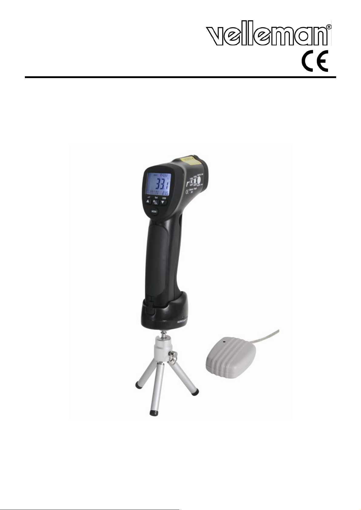
DVM8855
HIGH TEMPERATURE INFRARED & K-TYPE THERMOCOUPLE THERMOMETER
THERMOMETER VOOR HOGE TEMPERATUREN - IR + THERMOKOPPEL TYPE K
THERMOMÈTRE POUR HAUTES TEMPÉRATURES - IR+ THERMOCOUPLE TYPE K
THERMOMETER FÜR HOHE TEMPERATUREN - INFRAROT + K-TYP-FÜHLER
TERMÓMETRO PARA ALTAS TEMPERATURAS - IR + TERMOPAR TIPO "K"
USER MANUAL 3
GEBRUIKERSHANDLEIDING 12
NOTICE D’EMPLOI 21
MANUAL DEL USUARIO 30
BEDIENUNGSANLEITUNG 39
Page 2
DVM8855
Figure 1
02/03/2009 © 2008 Velleman Components nv
2
Page 3
DVM8855
User manual
1. Introduction
To all residents of the European Union
Important environmental information about this product
This symbol on the device or the package indicates that disposal of the device after its
lifecycle could harm the environment. Do not dispose of the unit (or batteries) as unsorted
municipal waste; it should be taken to a specialized company for recycling. This device
should be returned to your distributor or to a local recycling service. Respect the local
environmental rules.
If in doubt, contact your local waste disposal authorities.
Thank you for choosing Velleman! Please read the manual thoroughly before bringing this device into
service. If the device was damaged in transit, do not install or use it and contact your dealer. Damage
caused by disregard of certain guidelines in this manual is not covered by the warranty and the
dealer will not accept responsibility for any ensuing defects or problems.
2. Safety Instructions
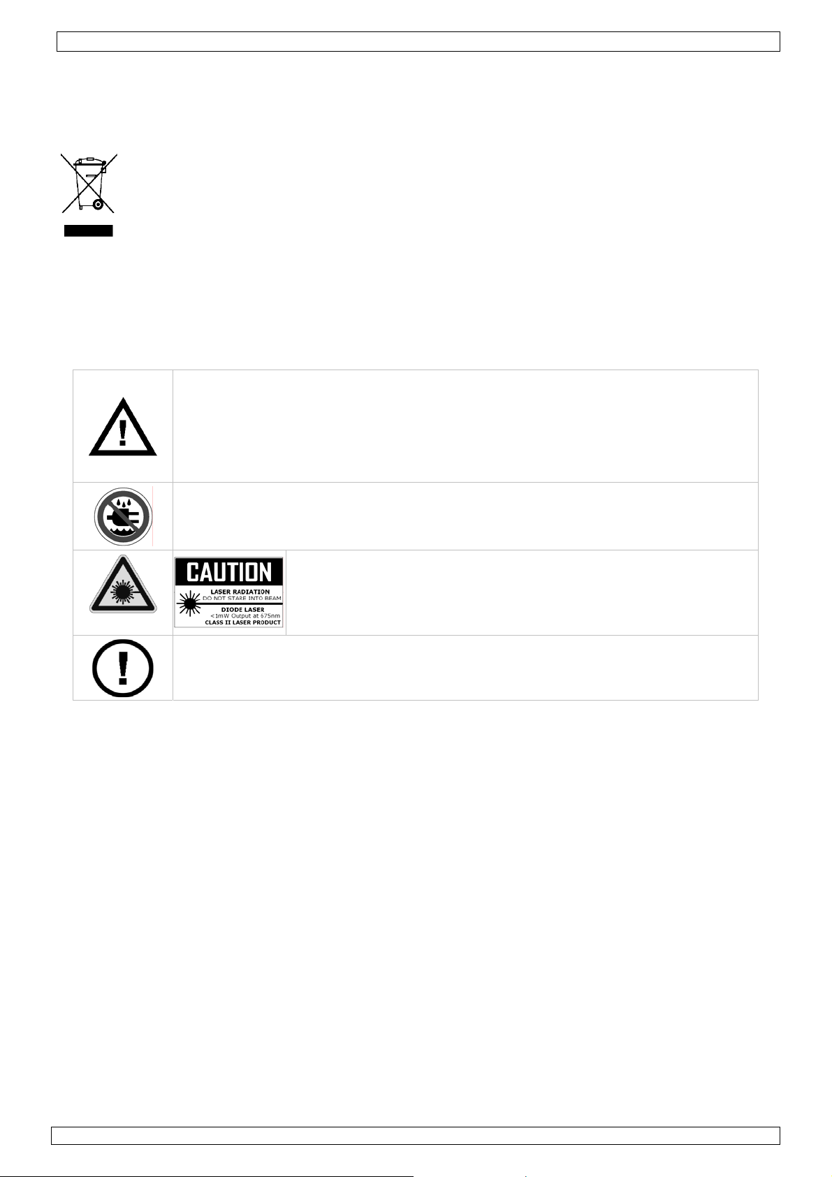
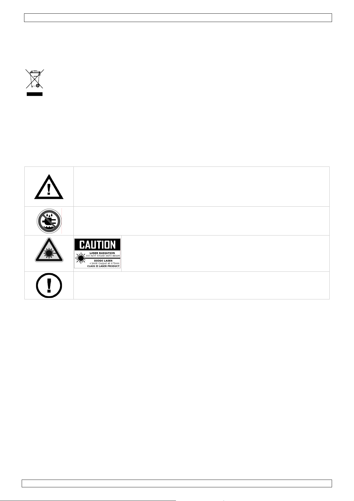
When device is in use, NEVER look directly or indirectly (reflectance) into
the laser beam. NEVER point the laser beam directly or via a reflecting surface
towards other people’s or animals’ eyes. Permanent eye damage will result. Use
extreme caution when the laser beam is turned on.
Do not point the laser beam towards highly explosive gases.
Keep out of reach of all children.
Keep this device away from rain, moisture, splashing and dripping liquids.
Visible laser radiation. Do not stare into the beam as eye damage
may occur. This device contains a class 2 laser.
CLASS II
DO NOT disassemble or open the cover. No user-serviceable parts inside. Refer
to an authorized dealer for service and/or spare parts.
Output power does not exceed 1 mW, wavelength 630~670nm.
3. General Guidelines
Refer to the Velleman® Service and Quality Warranty on the last pages of this manual.
• Protect this device from shocks and abuse. Avoid brute force when operating the device.
• Protect the device against extreme heat and dust.
• Familiarise yourself with the functions of the device before actually using it.
• All modifications of the device are forbidden for safety reasons.
• Only use the device for its intended purpose. Using the device in an unauthorised way will void the
warranty.
• Damage caused by disregard of certain guidelines in this manual is not covered by the warranty and
the dealer will not accept responsibility for any ensuing defects or problems.
• Note that damage caused by user modi fi ca ti ons to the device is not covered by the warranty.
4. Features
• professional device, quick and easy to use
• wireless USB connection for data-logging on PC
• Infrared and K-type probe measurements
• very high temperature range
• very high distance to target ratio (30:1)
• built-in laser pointer
• temperature readout in °C or °F
• LCD display with backlight
• data-hold, auto power-off and lock-on function
• MIN, MAX, DIF, AVG, HAL, LAL and record functions
• 20 memory locations for memorising temperatures
02/03/2009 © 2008 Velleman Components nv
3
Page 4
DVM8855
• 1mv/°F (1.8mV/°C) analogue output
• adjustable emissivity
• high and low alarm
• contents: manual, tripod, K-type thermocouple, wireles s USB receiver, wireless USB transmitter,
software, power supply, connection lead for mV output, carrying case
5. Overview
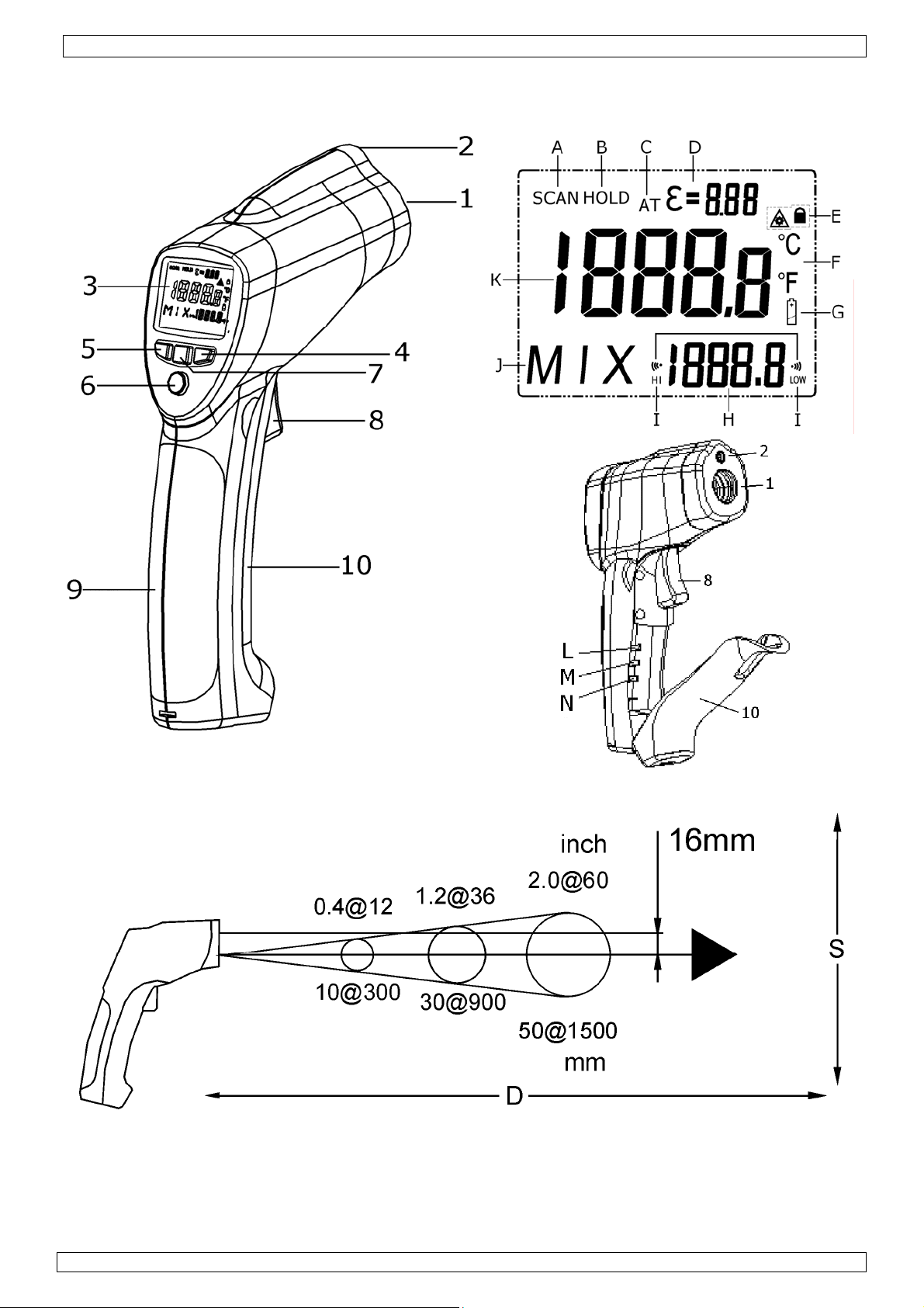
Refer to the drawings on page 2 of this manual.
1 IR sensor 6 mode button
2 laser pointer beam 7 laser/backlight button
3 LCD display 8 measurement trigger
4 down button 9 grip
5 up button 10 battery cover
display F °C or °F indication
A scan indication G low battery indication
B hold indication H MAX, MIN, DIF, AVG, HAL, LAL, Tk and memory values
C auto emissivity I high and low alarm indication
D emissivity indication and value J indication for H
E lock and laser ON indication K current measurement value
inside battery compartment M lock on/off switch
L °C and °F switch N alarm set switch
6. Operation
• Hold the thermometer by the grip [9] and point the IR sensor [1] towards the surface of which the
temperature needs to be measured.
• Pull and hold the measurement trigger [8]. The LCD display [3] shows the current temperature
[K].
• During measurement, the word ‘SCAN’ [A] is visible in the LED display. When the measurement
stops (trigger [8] released), the word ‘HOLD’ [B] is shown. The last measured value will remain on
the display until the measurement trigger [8] is pulled again, or when the thermometer powers-off
automatically (after ± 7 seconds).
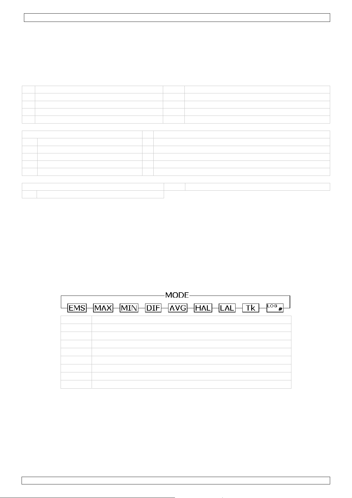
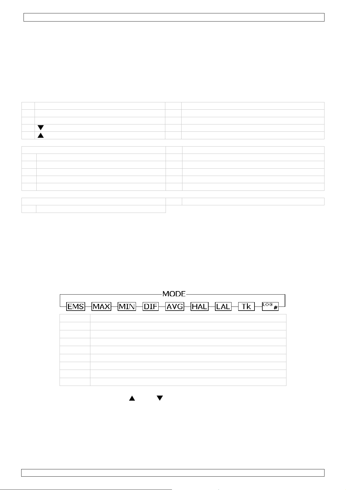
• Depending on the mode, the bottom of the screen shows the MAX, MIN, DIF, AVH, HAL, LAL Tk or
memory values. Use the mo d e b u t ton [6] to scroll through the modes of the device. The mode [J]
and corresponding value [H] are shown on the display.
EMS Emissivity
(*)
MAX Highest measured value
MIN Lowest measured value
DIF Difference between the highest and lowest measured value
AVG Average value of the temperature
HAL Higher alarm limit
LAL Lower alarm limit
Tk Temperature measured via thermocouple
LOG # Show memory location number # (max. 20) value
(*)
For more information on emissivity, refer to §8 Useful information.
• To set EMS, HAL or LAL, use the up [5] or down [4] button to adjust the value and press the mode
button [6] again to save the value and go to the next item. To cancel mode selection, pull the
measurement trigger [8]. Pushing the mode button [6] after setting the lower alarm limit will start
the set-up cycle again.
• Note that MAX, MIN, DIF and AVG only apply to the current measuring session (time between pulling
the trigger [8] and releasing it). Their value is reset when a new measurement starts or the
thermometer switches off.
• To switch between measurements in °C and °F, open the battery cover [10]. The battery cover has
a hinge at the bottom of the device. Hold the battery cover at the top (next to the measurement
trigger [8]) and gently pull away from the device.
02/03/2009 © 2008 Velleman Components nv
4
Page 5

DVM8855
• The °C/°F switch [L] is located inside the battery compartment under the battery. Move this switch
to the desired setting. The current setting is indicated [F] in the display.
• Also under the battery, there is a lock switch [M]. Move this switch to the ON-position for
continuous measurement. The current setting is indicated with a lock symbol [E] in the display.
Start measuring by pulling the measurement trigger [8] once. Consider disabling the laser targeting
beam in continuous measuri ng mo de to save batte ry po we r. To s to p and d i sable lock m o de, s et the
switch [M] back to the OFF-position. In lock mode, it is still possible to adjust EMS, HAL and LAL
values.
• The third switch under the battery is the alarm set switch [N]. Move this switch to the ON-position
to enable alarm warnings when high or low alarm limits are exceeded. When enabled, a Hi- and LOW
indication [I] are shown on the display.
• Close the battery cover [10] by pushing it back towards the device until it snaps in place.
• When the measured value exceeds a preset alarm limit, an audible alarm signal will be produced
(when the alarm set switch [N] is set to ON), and the according alarm icon in the display [I] will
flash. Alarm will stop when temperature is back within preset limits.
• Push the laser/backlight button [7] to cycle through the laser and backlight options (not available in
memory mode (LOG # displayed). Note that the laser beam is only an aiming aid, be careful when
using it. Refer to the safety instructions.
Push result
1 backlight on
2 backlight on and laser enabled
3 backlight off and laser enabled
4 backlight off and laser disabled
• To measure temperatures using the thermocouple, first connect the thermocouple to the bottom of
the grip [9]. The connector is slotted and can be inserted only one way. Do not force. Use the mode
button [6] to go to Tk mode [J] and read the thermocouple temperature [H].
• The DVM8855 has 20 memory locations to store measurements. Use the mode button [6] to go to
LOG mode [J] and use the up [5] or down [4] button to scroll through the memory. To store a
measured value, go to the desired memory location and press the laser/backlight button [7].
Emissivity measurement
• To determine the emissivity of a surface, go to EMS mode using the mode button [6]. Conne ct the
thermocouple and attach it to the surface. Pull and hold the measurement trigger [8] (consider
placing the meter in lock mode [M]). Press and ho ld the laser/backlight button [7] until the EMS
indication [J] starts flashing and the thermocouple measured value is shown [H]. Point the IR
sensor [1] towards the surface, close to the location of the thermocouple. When Tk a n d IR
measurements are identical and stable, press the up [5] or down [4] button. The measured
emissivity [C] is indicated [D] and normal measurement can be resumed.
Notes on emissivity measurement:
• Allow at least 15min for the thermocouple to reach the surface temperature.
• The measuring surface should be higher in temperature than the environment, e.g. 100°C surface
temperature will provide a more accurate measurement of the emissivity.
• When the temperature measured with the thermocouple differs from the one measured with the IR
sensor, or measuring points differ, the obtained emissivity will be wrong, or ERR is displa yed.
• To exit emissivity measurement at any time, press the mode button [6].
General remarks:
• The device powers off automatically (after ± 7 seconds) when no activity is detected, unless it is
in lock mode.
• The unit will not measure correctly through transparent surfaces (e.g. glass), as it will measure the
surface temperature of the transparent surface.
• Steam, dust, smoke etc. will have a negative impact on the measurements accuracy.
• Measurements on shiny and/or polished surfaces are not recommended.
• To use the tripod, first plug the DVM8855 in the transmitter stand. Place the connector pins at
the front of grip [9] first, then tilt down until the meter snaps in place. To remove, lift the back
up first. Screw the tripod into the bottom of the transmitter stand and extend the legs of the
tripod to set the preferred height. Position the head and use the screw on the side to secure it.
02/03/2009 © 2008 Velleman Components nv
5
Page 6
DVM8855
7. Software installation and use
Driver installation
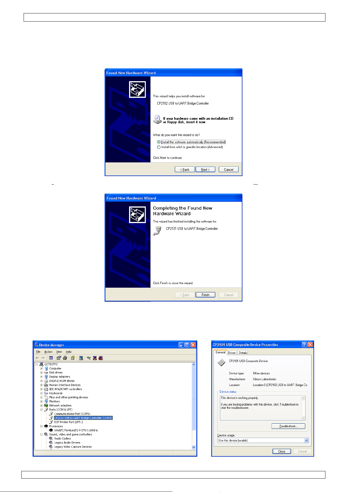
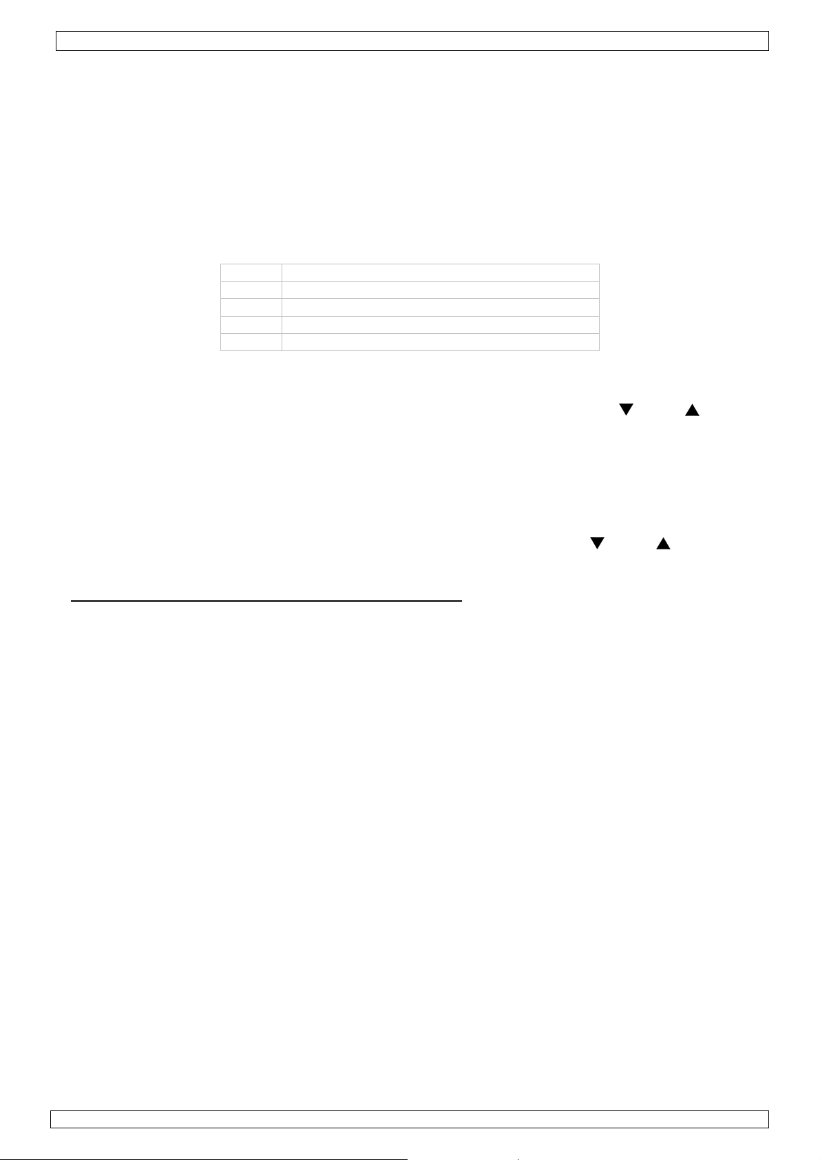
• Plug the USB connector of the receiver into a free powered USB port of a PC. The system should
recognize the new hardware automatically: CP2102 USB to UART Bridge Controller.
• The ‘Found New Hardware Wizard’ pops up:
• Select ‘I
• The ‘Completing the Found New Hardware Wizard’ window pops up. Click on ‘Finish’.
nstall the software automatically (Recommended)’ option and click ‘Next >’.
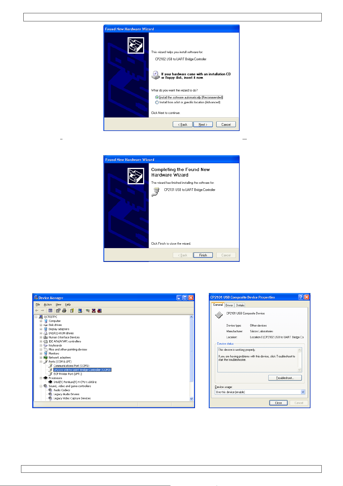
• Verify the driver installation in the Device manager. Go to ‘M y computer’ – ‘System information’ –
tab ‘Hardware’ and click on ‘Device Manager’. Look for ‘CP2102 USB to UART Bridge Controller’
under section ‘Ports (COM & LPT)’. A COM-port was assigned to this bridge controller; it is
mentioned between brackets at the end of the line. Remember this number as it is needed to
configure the software. Double click (left) on the device name to see more details.
02/03/2009 © 2008 Velleman Components nv
6
Page 7
DVM8855
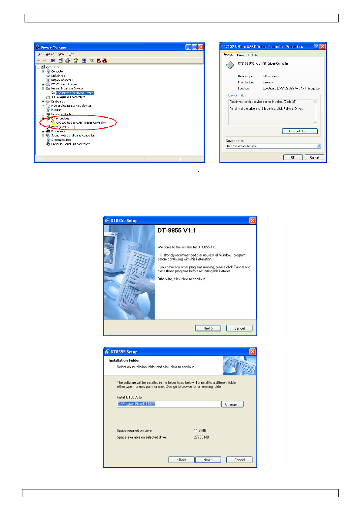
• If the driver is not installed correctly, device manager shows a yellow exclamation mark in front of
the device name.
• Double click (left) on the device name and click on ‘Rei
nstall Driver…’ or go to the ‘Driver’-tab to
uninstall the driver. The driver can be found on the included CD-ROM (CP2101WIN under DT-
8855).
Software installation
• Insert the included CD-ROM into the CD-drive of the PC. Locate the file ‘DT8855.exe’ under the
‘DT-8855’ directory and double click (left) on it to start the installation.
• Click on ‘Next >’ and in the next screen, choose a destination folder for the software.
• In the following screen, click ‘Next >’.
02/03/2009 © 2008 Velleman Components nv
7
Page 8
DVM8855
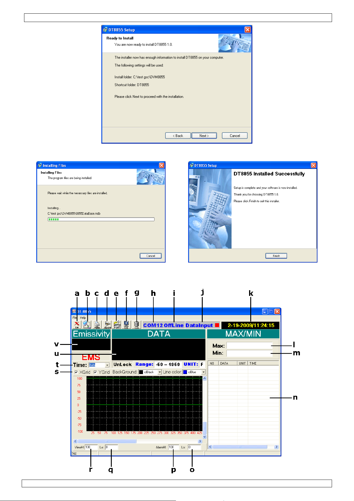
• An installation progress screen is shown, followed by the ‘DT8855 Installed Successfully’ screen.
Click ‘Finish’ to finalize the software installation.
Software description
• Locate the file ‘DT-8855.exe’ in the folder where the software was installed and double click (left)
on it. The application opens.
02/03/2009 © 2008 Velleman Components nv
8
Page 9
DVM8855
a exit the application l max. measured temperature
b select com port m min. measured temperature
c print data n data window
d switch between online and offline o lower alarm limit
e save/load data p higher alarm limit
f clear graph q set lower range graph
g clear all data r set higher range graph
h current COM port s graph display setup
i status (OnLine = connected) t set sampling time
j data input (red = receiving) u current temperature
k current date and time v current emissivity setting
Using the wireless link
Note: connection can only be established when the thermometer is in scan mode. Consider placing
the meter in lock mode [M] for easy handling.
• Make sure the USB connector of the receiver is plugged into the PC. The red status LED on the
receiver lights up.
• Plug the DVM8855 in the transmitter stand. Place the connector pins at the front of grip [9] first,
than tilt down until the meter snaps in place. To remove, lift the back up first.
• Connect the DC connector of the included power adaptor into the transmitter stand and plug the
other end into the mains (100~240CAC, 50~60Hz).
• Start the DT-8855 software and set the correct com port [b], most likely this will be COM3 (verify
with ‘device manager’).
• Press the ‘ON’-button on the transmitter stand and press the online button [d]. When the
thermometer is in SCAN mode, the status LEDs of both transmitter and receiv er start blinking in
sync, indicating there is communication. Data will be shown in the data window [n].
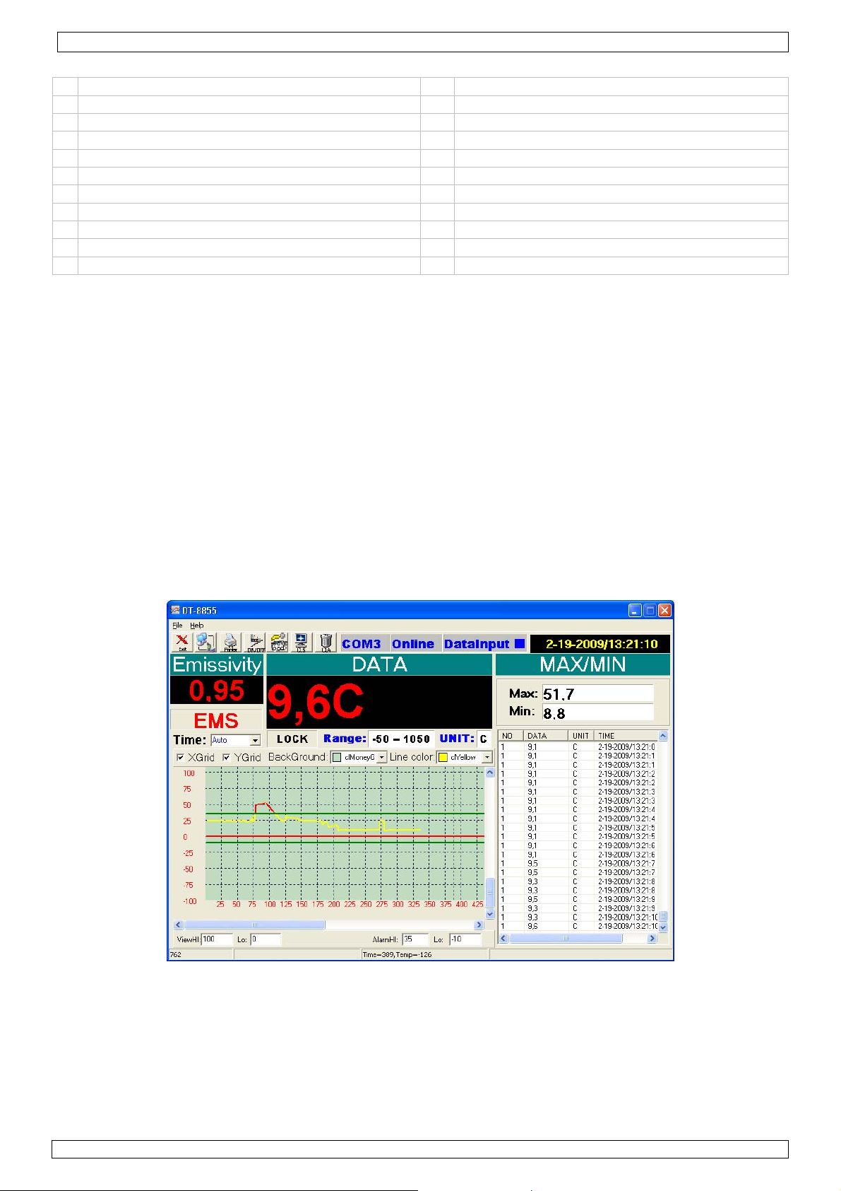
• Setup the software as desired. Set the sample time [t], this is the time the software waits
between 2 interrogations of the thermometer. Set the lower [o] and higher [p] time limits. These
are indicated by a horizontal line on the selected temperature. When the temperature crosses
these lines, the graph will turn red (see example below).
• The measured data can be saved and recalled [e]. The file format is .xls (Excel). Data which is
not saved prior to closing the application is lost.
• Note that the transmitter stand also has an analogue output which can be connected to a plotter
(not incl.) or similar device. Signal scale is 1mV/°F (±1.8mV/°C).
02/03/2009 © 2008 Velleman Components nv
9
Page 10
DVM8855
8. Useful information
Working principle
The Infra Red sensor of the unit detects energy that is emitted, reflected and transmitted by a
surface. This energy is focussed onto a detector that converts this information into a temperature
reading. The laser beam is only used for aiming purposes.
Ambient temperature
The thermometer automatically compensates ambient temperature conditions. Allow the
thermometer to stabilise to ambient temperature for at least 30 minutes for accurate
measurements.
Surface temperature
When going from low temperature to high temperature measurements or vice versa, the IR sensor
of the thermometer needs a few minutes to adjust.
Distance and spot size
Refer to the drawing on page 2 of this manual.
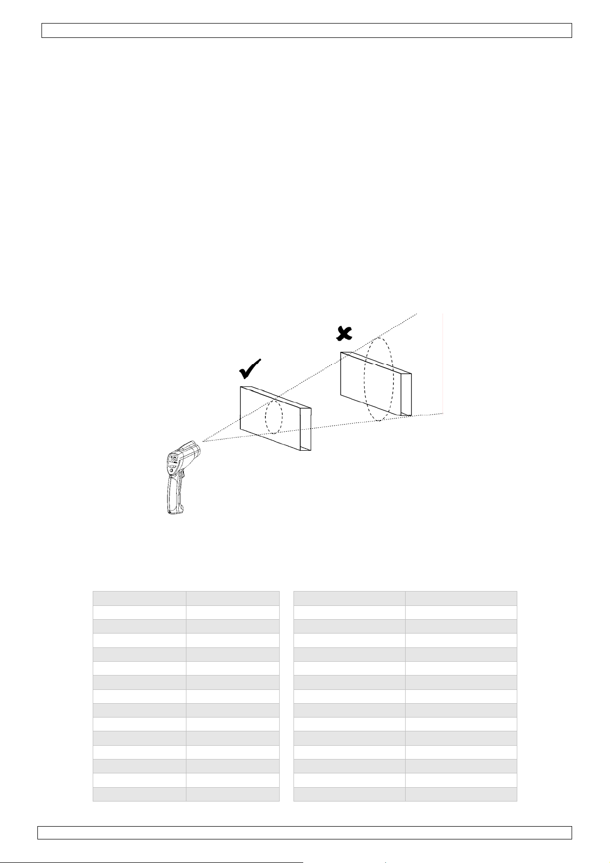
As the distance (D) from the object increases, the spot size (S) of the area measured by the unit
becomes larger. The focal point for this unit is 914mm (36”). Note that the laser beam points 16mm
above the measurement centre point.
Field of view
The target must be larger than the spot size to ensure correct measurement. This means that for
smaller targets, the thermometer must be held closer to the target. For best accuracy, make sure
the target is at least twice as large as the spot size.
Emissivity
Emissivity describes the energy-emitting characteristics of materials. Most organic or oxidized
surfaces have an emissivity of ±0.95 (default setting). Measuring shiny or polished surfaces will be
inaccurate. Use some masking tape or paint to compensate, allow sufficient time for the tape or
paint to reach the surface temperature.
Substance Emissivity Substance Emissivity
Asphalt 0.90 to 0.98 Cloth (black) 0.98
Concrete 0.94 Human skin 0.98
Cement 0.96 Leather 0.95 to 1.00
Sand 0.90 Charcoal (powder) 0.96
Earth 0.92 to 0.96 Lacquer 0.80 to 0.95
Water 0.92 to 0.96 Lacquer (matt) 0.97
Ice 0.96 to 0.98 Rubber (black) 0.94
Snow 0.83 Plastic 0.85 to 0.95
Glass 0.90 to 0.95 Timber 0.90
Ceramic 0.90 to 0.94 Paper 0.70 to 0.94
Marble 0.94 Chromium oxides 0.81
Plaster 0.80 to 0.90 Copper oxides 0.78
Mortar 0.89 to 0.91 Iron oxides 0.78 to 0.82
Brick 0.93 to 0.96 Textiles 0.90
02/03/2009 © 2008 Velleman Components nv
10
Page 11
DVM8855
9. Cleaning and storage
• The IR sensor [1] is the most delicate part of the thermometer and should be kept clean at all
times. To do this, only use a soft cloth or cotton bud. Do not use excessive pressure on the
sensor.
• Wipe the other parts of the thermometer regularly with a dry cloth. Do not use abrasive solutions or
solvents.
• Do not submerge the thermometer in water or any other liquid.
• There are no user-serviceable parts. Contact your dealer for spare parts if necessary.
• The device must be stored in a place with temperature conditions between -20°C and +60°C (-4°F
and +140°F) and relative humidity lower than 80%.
10. Battery
• When the battery indicator [G] indicates low battery, replace the battery with a new one.
• Open the battery cover [10]. The battery cover has a hinge at the bottom of the device. Hold the
battery cover at the top (next to the measurement trigger [8]) and gently pull away from the
device.
• If necessary switch the lock switch [L] to the OFF-position first.
• Connect a new 9V battery to the thermometer with the battery clip and insert the battery in the
battery compartment.
• Push the cover back towards the device until it snaps into place.
WARNING: malfunction may occur if the power is on when the battery is
replaced. Do not attempt to recharge non-rechargeable batteries, do not
puncture or do not throw batteries in fire as they might explode. Dispose of
batteries in accordance with local regulations.
Keep the battery away from children.
11. Technical specifications
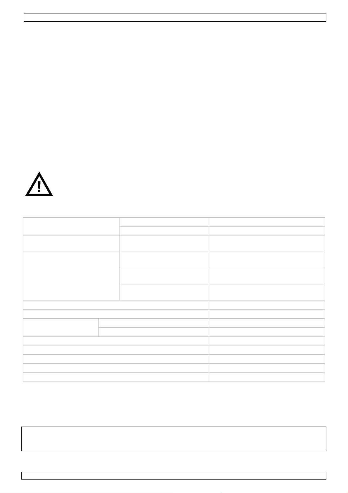
measurement range
accuracy K-type probe
= 25°C)
(T
amb
T
obj
T
accuracy IR
= 25°C)
(T
amb
T
T
obj
response time < 1 sec
emissivity range 0.1 ~ 1.0 adjustable
wireless USB link
wavelength 8µm - 14µm
distance-to-spot ratio D/S = 30:1
power supply 1x 9V E-block battery (6F22C, incl.)
dimensions 100 x 56 x 230mm
weight 290g
Use this device with original accessories only. Velleman nv cannot be held responsible in
the event of damage or injury resulted from (incorrect) use of this device.
For more info concerning this product, please visit our website www.velleman.eu.
The information in this manual is subject to change without prior notice.
© COPYRIGHT NOTICE
The copyright to this manual is owned by Velleman Components nv. All worldwide rights reserved.
No part of this manual or the described software may be copied, reproduced, translated or reduced to any electronic medium
or otherwise without the prior written co nsent of the copyright holder.
infrared -50°C ~+1050°C (-58°F ~ +1922°F)
K-type probe -50°C ~+1370°C (-58°F ~ +1999°F)
= -50°C ~ 1000°C ± 1.5% of rdg ± 3°C (5.4°F)
= -20°C ~ 200°C
obj
(-4°F ~ 392°F)
= 200°C ~ 538°C
obj
(392°F ~ 1000°F)
= 538°C ~ 1050°C
(1000°F ~ 1922°F)
± 1.5% of rdg ± 2°C (3.6°F)
± 2.0% of rdg ± 2°C (3.6°F)
± 3.5% of rdg ± 5°C (9°F)
frequency 433MHz
range 10m
02/03/2009 © 2008 Velleman Components nv
11
Page 12
DVM8855
Gebruikershandleiding
1. Inleiding
Aan alle ingezetenen van de Europese Unie
Belangrijke milieu-informatie betreffende dit product
Dit symbool op het toestel of de verpakking geeft aan dat, als het na zijn levenscyclus wordt
weggeworpen, dit toestel schade kan toebrengen aan het milieu. Gooi dit toestel (en
eventuele batterijen) niet bij het gewone huishoudelijke afval; het moet bij een
gespecialiseerd bedrijf terechtkomen voor recyclage. U moet dit toestel naar uw verdeler of
naar een lokaal recyclagepunt brengen. Respecteer de plaatselijke milieuwetgeving.
Hebt u vragen, contacteer dan de plaatselijke autoriteiten inzake verwijdering.
Dank u voor uw aankoop! Lees deze handleiding grondig voor u het toestel in gebruik neemt. Werd
het toestel beschadigd tijdens het transport, installeer het dan niet en raadpleeg uw dealer. De
garantie geldt niet voor schade door het negeren van bepaalde richtlijnen in deze handleiding en uw
dealer zal de verantwoordelijkheid afwijzen voor defecten of problemen die hier rechtstreeks
verband mee houden.
2. Veiligheidsinstructies
Kijk nooit rechtstreeks of onrechtstreeks in de laserstraal. Richt de straal
NOOIT (direct of via een reflecterend object) in de richting van de ogen om
permanente oogletsels te voorkomen. Gebruik een ingeschakeld toestel met
voorzichtigheid. Richt de straal nooit in de richting van explosieve gassen.
Houd dit toestel uit de buurt van kinderen.
Houd dit toestel uit de buurt van regen, vochtigheid en opspattende vloeistoffen.
Zichtbare laserstraal. Kijk nooit in de straal om oogletsels te
vermijden. Dit toestel is uitgerust met 2 laserstralen.
KLASSE 2
De behuizing mag nooit geopend worden. De gebruiker mag geen onderdelen
vervangen. Bestel eventuele reserveonderdelen bij uw dealer.
Het uitgangsvermogen bedraagt niet meer dan 1 mW, golflengte
630~670 nm.
3. Algemene richtlijnen
Raadpleeg de Velleman® service- en kwaliteitsgarantie achteraan deze handleiding.
• Bescherm dit toestel tegen schokken. Vermijd brute kracht tijdens de bedieni ng van dit toestel.
• Bescherm dit toestel tegen extreme temperaturen, stof en vochtigheid.
• Leer eerst de functies van het toestel kennen voor u het gaat gebruiken.
• Om veiligheidsredenen mag de gebruiker geen wijzigingen aanbrengen aan het toestel.
• Gebruik het toestel enkel waarvoor het gemaakt is. Bij onoordeelkundig gebruik vervalt de
garantie.
• De garantie geldt niet voor schade door het negeren van bepaalde richtlijnen in deze handleiding
en uw dealer zal de verantwoordelijkheid afwijzen voor defecten of problemen die hier
rechtstreeks verband mee houden.
• Schade door wijzigingen die de gebruiker heeft aangebracht aan het toestel vallen niet onder de
garantie.
4. Eigenschappen
• professionele thermometer, gemakkelijk en snel te gebruiken
• datalogging op pc via draadloze USB-aansluiting
• metingen: infrarood of via thermokoppel type K
• hoog temperatuurbereik
• zeer hoge verhouding afstand-meetpunt (30:1)
• ingebouwde laserpointer
• weergave van de temperatuur in °C of °F
• lcd-scherm met achtergrondverlichting
02/03/2009 © 2008 Velleman Components nv
12
Page 13
DVM8855
• dataholdfunctie, automatische uitschakeling en vegrendeling
• MIN-, MAX-, DIF-, AVG-, HAL-, LAL- en recordmetingen
• 20 geheugenbanken voor temperatuuropslag
• 1 mv/°F (1,8 mV/°C) analoge uitgang
• instelbare emissiviteit
• hoog en laag alarm
• inhoud: handleiding, statief, thermokoppel type K, draadloze USB-ontvanger, draadloze USB-
zender, software, voedingsadapter, aansluitkabel voor mV-uitgang, draagkoffer
5. Omschrijving
Raadpleeg de figuren op pagina 2 van deze handleiding.
1 IR-sensor 6 modustoets
2 laserpointer 7 laser/achtergrondverlichting
3 lcd-scherm 8 meetknop
4 -toets 9 handvat
5 -toets 10 batterijvak
lcd-display F °C /°F
A aanduiding ‘scan’ G laag/hoog alarm
B aanduiding ‘data hold’ H MAX, MIN, DIF, AVH, HAL, LAL en Tk
C automatische emissiviteit I laag/hoog alarm
D emissiviteit en w a a r d e J H
E vergrendeling, laser ingeschakeld K waarde-uitlezing
binnenkant batterijvak M vergrendelschakelaar
L schakelaar °C/°F N alarmschakelaar
6. Gebruik
• Houd de thermometer bij het handvat [9] vast en richt de IR-sensor [1] naar het te meten object.
• Houd de meetknop [8] ingedrukt. De display [3] geeft de gemeten waarde weer [K].
• Tijdens de meting verschijnt de aanduiding ‘SCAN’ [A]. Bij het loslaten van de meetknop [8]
verschijnt de aanduiding ‘HOLD’ [B]. De laatst gemeten waarde blijft o p de display weer gege ven to t
de meetknop [8] opnieuw wordt ingedrukt of tot de thermometer automatisch uitschakelt (na ± 7
seconden).
• De aanduiding MAX, MIN, DIF, AVH, HAL, LAL of Tk, of de opgeslagen waarden verschijnen
naargelang de ingestelde modus. Scroll door de opties met de modustoets [6]. De modus [J] en
overeenkomstige waarde [H] worden op de di spla y weer gege ven.
(*)
EMS emissiviteit
MAX hoogst gemeten waarde
MIN laagst gemeten waarde
DIF verschil tussen hoogste en laagste waarde
AVG gemiddelde temperatuurwaarde
HAL hoog alarm
LAL laag alarm
Tk temperatuur gemeten via thermokoppel
LOG
# waarde van de locatie in het geheugen (max. 20)
• Stel EMS, HAL of LAL in met toets
(*)
Voor meer informatie over emissiviteit, raadpleeg §8 Nuttige informatie.
[4] of [5] en bewaar de waarde met de modustoets [6].
Verlaat het modusmenu door de meetknop [8] in te drukken. Druk de meetknop [6] opnieuw in na
het instellen van de HAL- en LAL-waarde om het instelmenu opnieuw op te starten.
• De functies MAX, MIN, DIF en AVG gelden enkel voor de huidige meting (tijd tussen het indrukken
en het loslaten van de meetknop [8]). De waarde wordt gewist bij een nieuwe meting of indien de
thermometer uitschakelt.
• Schakel tussen °C en °F door eerst het batterijvak [10] open te schuiven. Plaats de
keuzeschakelaar [L] onder de batterij. De eenheid [F] wordt op de display weergegeven.
02/03/2009 © 2008 Velleman Components nv
13
Page 14
DVM8855
• Het batterijvak [10] bevat ook een vergrendelschakelaar [M]. Plaats deze schakelaar op ON voor
ononderbroken metingen. De ingestelde optie [E] wordt op de display weergegeven. Start de
meting door de meetknop [8] eenmaal in te drukken (schakel de laserpointer uit om de batterij te
sparen). Schakel de vergrendeloptie uit door de schakelaar [M] op OFF te plaatsen. In
vergrendelmodus kunt u nog steeds de EMS-, HAL- en LAL-waarde instellen.
• Met de derde schakelaar [N] stelt u de alarmwaarde in. Plaats de schakelaar op ON om de functie in
te schakelen (de thermometer piept indien de limieten worden overschreden). Een aanduiding (HI of
LOW [I]) verschijnt op de display.
• Sluit het ba tt e ri j v a k [10].
• Druk toets [7] in om de verschillende laser- en achtergrondverlichtingopties (niet beschikbaar in
geheugenmodus (‘
LOG
#’ wordt weergegeven) te doorlopen. De laserpointer is enkel een richthulp.
Wees voorzichtig bij het gebruik van deze laser en raadpleeg eerst de veiligheidsinstructies.
druk resultaat
1 achtergrondverlichting aan
2 achtergrondverlichting en laser aan
3 achtergrondverlichting uit en laser aan
4 achtergrondverlichting en laser uit
• Temperatuurmeting via het thermokoppel: Koppel het thermokoppel voorzichtig onderaan het
handvat [9]. Ga naar de Tk-modus [J] met de modustoets [6] en lees de gemeten waarde [H] af.
• De DVM8855 beschikt over 20 geheugenbanken waar u de metingen kunt opslaan. Ga naar de
LOG-modus [J] met de modustoets [6] en scroll door de geheugenbanken met
[4] of [5]. Ga
naar de gewenste geheugenbank en druk op de laser-/achtergrondverlichtingtoets om een gemeten
waarde in het geheugen op te slaan.
Het meten van emissiviteit
• Ga naar de EMS-modus met de modustoets [6]. Koppel het ther mokoppel aa n de the rmome ter en
bevestig de meetsonde aan het te meten oppervlak. Houd de meetknop [8] ingedrukt of schakel de
vergrendelschakelaar [M] in. Houd de laser-/achtergrondverlichtingtoets ingedrukt tot EMSaanduiding [J] begint te knipperen en de waarde wordt weergegeven [H]. Richt de IR-sensor [1]
naar het te meten oppervlak, zo dicht mogelijk bij de meetsonde. Druk op
[4] of [5]
wanneer de Tk- en IR-metingen identiek en stabiel zijn. De gemeten emissiviteit [C] wordt op de
display weergegeven [D].
Opmerkingen in verband met het meten van emissiviteit:
• Laat het thermokoppel gedurende 15 minuten met het te meten oppervlak in contact zodat het de
oppervlaktetemperatuur kan opnemen.
• Voor de beste meetresultaten, zorg ervoor dat de temperatuur van het te meten oppervlak hoger
is dan de omgevingstemperatuur.
• Indien de gemeten temperatuur bij een Tk- en een IR-meting te veel verschilt, of bij het meten
van twee verschillende punten op hetzelfde oppervlak, zal ERR op de display verschijnen.
• Druk op de modustoets [6] om de emissiviteitsmeting te verlaten.
Opmerkingen:
• De thermometer schakelt automatisch uit na ± 7 seconden, uitgenomen indien de
vergrendelmodus is ingeschakeld.
• Metingen verricht doorheen transparante objecten, bv. glas, zijn niet mogelijk. De gemeten
waarde is die van het transparante object.
• Damp, stof en rook beïnvloeden de nauwkeurigheid van de meting.
• Het is niet aan te raden de temperatuur van een gepolijst of glanzend object te meten.
• Gebruik met statief: Koppel uw DVM8855 eerst aan het zendstation. Plaats de pinnetjes
vooraan de greep [9] en klik daarna op zijn plaats (verwijder door de meter naar voren te
hellen). Schroef het statief onderaan het station vast en vouw de pootjes open. Richt de meter
en bevestig met de schroef.
7. Installatie en gebruik van de software
De driver installeren
• Plug de USB-stekker van de ontvanger in een vrije USB-poort van uw pc. Het systeem herkent
automatisch de nieuwe hardware: CP2102 USB to UART Bridge Controller.
• De wizard met vermelding ‘Found New Hardware Wizard’ verschijnt:
02/03/2009 © 2008 Velleman Components nv
14
Page 15
DVM8855
• Kies voor ‘I
nstall the software automatically (Recommended)’ en klik op ‘Next >’.
• Een venster met vermelding ‘Completing the Found New Hardware Wizard’ verschijnt. Klik op
‘Finish’.
• Controleer de geïnstalleerde hardware in de Device Manager. Ga naar ‘My Computer’ – ‘System
Properties’ – tab ‘Hardware’ en klik op ‘Device Manager’. Dubbelklik en open ‘CP2102 USB to UART
Bridge Controller’ onder ‘Ports (COM & LPT)’ voor meer details. De COM-poort tussen haakjes hebt
u nodig om de software te configureren.
02/03/2009 © 2008 Velleman Components nv
15
Page 16

DVM8855
• De Device Manager toont een geel uitroepteken voor de hardware indien de software niet correct
werd geïnstalleerd.
• Dubbelklik op de bestandsnaam en klik op ‘Rei
nstall Driver…’ of open de tab ‘Driver’ om de driver
te de-installeren. De driver is beschikbaar op de meegeleverde cd-rom (CP2101WIN onder DT-
8855).
De software installeren
• Plaats de meegeleverde cd-rom in de cd-romdrive van uw pc. Dubbelklik op het bestand
‘DT8855.exe’ onder de directory ‘DT-8855’ om de installatieprocedure te starten.
• Klik op ‘Next >’ en kies vervolgens de doelmap voor de software.
02/03/2009 © 2008 Velleman Components nv
16
Page 17

DVM8855
• Klik op ‘Next >’.
• U kunt het verloop van de procedure volgen dankzij de balk. Klik na het verschijnen van de
melding ‘DT8855 Installed Successfully’ op ‘Finish’ om de installatie te voltooien.
Omschrijving van de software
• Dubbelklik op het bestand ‘DT-8855.exe’ in de doelmap van de software om de toepassing te
openen.
02/03/2009 © 2008 Velleman Components nv
17
Page 18

DVM8855
a toepassing verlaten l max. gemeten temperatuur
b COM-poort selecteren m min. gemeten temperatuur
c data printen n datavenster
d schakelen tussen online en offline o drempel laag alarm
e data opslaan/laden p drempel hoog alarm
f grafiek wissen q instellen laagste bereik grafiek
g alle data wissen r instellen hoogste bereik grafiek
h huidige COM-poort s instellen grafiekdisplay
i status (OnLine = aangesloten) t instellen bemonsteringfrequentie
j data-input (rood = ontvangst) u huidige temperatuur
k huidige datum en tijd v huidige instelling emissiviteit
Draadloos gebruik
Opmerking: De aansluiting is enkel mogelijk indien de thermometer in scanmodus staat. Schakel
de vergrendelschakelaar [M] in indien gewenst.
• Koppel de USB-stekker van de ontvanger aan de pc. De rode statusled op de ontvanger licht op.
• Koppel uw DVM8855 eerst aan het zendstation. Plaats de pinnetjes vooraan de greep [9] en klik
daarna op zijn plaats (verwijder door de meter naar voren te hellen).
• Plug de DC-stekker van de meegeleverde voeding in het zendstation en koppel de voeding aan het
lichtnet (100 ~ 240 VAC, 50 ~ 60 Hz).
• Start de DT-8855-software en kies de correcte COM-poort [b] (doorgaans poort 3, controleer in de
Device Manager).
• Druk op de ON-knop op het zendstation en klik op OnLine [d]. Bij communicatie en indien de
thermometer in scanmodus staat, zullen de statusleds op het zendstation en de ontvanger
synchroon knipperen. De data wordt in het venster [n] weergegeven.
• Stel de software naar wens in: bemonsteringsfrequentie [t] (wachttijd van de software tussen
twee monsters door de thermometer) en drempel laag [o] en hoog alarm [p] (weergegeven door
de groene horizontale lijn in de grafiek). Bij overschrijding van deze drempels kleurt de curve rood
(zie voorbeeld hieronder).
• U kunt de gemeten data opslaan en opnieuw opvragen [e]. Het bestandsformaat is .xls (Excel).
Data die niet opgeslagen is, zal bij het sluiten van de toepassing onherroepelijk gewist
worden.
• Het zendstation heeft ook een analoge aansluiting voor een plotter (niet meegeleverd) of
gelijkaardig toestel. Schaal: 1 mV/°F (± 1,8 mV/°C).
02/03/2009 © 2008 Velleman Components nv
18
Page 19

DVM8855
8. Nuttige informatie
Werkprincipe
De infraroodsensor van dit toestel neemt de uitgestraalde energie van een voorwerp op. Deze
energie wordt door de detector omgezet in een temperatuurwaarde. De laserpointer dient enkel als
richthulp.
Omgevingstemperatuur
Deze thermometer houdt automatisch rekening met de omgevingstemperatuur en compenseert de
waarden. Wacht daarom een 30-tal minuten tot de thermometer op kamertemperatuur gekomen is
alvorens hem te gaan gebruiken.
Oppervlaktetemperatuur
Laat de sensor enkele minuten rusten indien u schakelt van meting van de hoge temperatuur naar
meting van de lage temperatuur en omgekeerd.
Verhouding afstand-meetpunt
Hoe groter de afstand (D) tot het te meten oppervlak, hoe groter het meetpunt (S). Het focale punt
bedraagt 914 mm (36”).
Gezichtsveld
Het te meten object dient groter te zijn dan het meetpunt zelf. Meet de temperatuur van kleine
objecten door de thermometer zeer dicht tegen dit object te houden. Zorg voor een object dat
minstens tweemaal zo groot is als het meetpunt voor de beste resultaten.
Emissiviteit
Onder emissiviteit verstaan wij de stralingsvermogen van een stof. De meeste organische of
geoxideerde oppervlakken hebben een emissiviteit van ± 0,95 (standaard instelling). Het meten van
glanzende of gepolijste oppervlakken levert onnauwkeurige resultaten op. Bedek het te meten
oppervlak met afdektape of verf en laat wacht tot de tape of de verf de temperatuur van het
oppervlak heeft bereikt.
Materiaal Emissiviteit Materiaal Emissiviteit
Asfalt 0,90 ~ 0,98 Zwarte stof 0,98
Beton 0,94 Menselijke huid 0,98
Cement 0,96 Leer 0,95 ~ 1,00
Zand 0,90 Houtskool 0,96
Aarde 0,92 ~ 0,96 Lak 0,80 ~ 0,95
Water 0,92 ~ 0,96 Lak (mat) 0,97
IJs 0,96 ~ 0,98 Rubber (zwart) 0,94
Sneeuw 0,83 Plastic 0,85 ~ 0,95
Glas 0,90 ~ 0,95 Hout 0,90
Keramiek 0,90 ~ 0,94 Papier 0,70 ~ 0,94
Marmer 0,94 Chroomoxides 0,81
Plaaster 0,80 ~ 0,90 Koperoxides 0,78
Mortier 0,89 ~ 0,91 IJzeroxides 0,78 ~ 0,82
Baksteen 0,93 ~ 0,96 Textiel 0,90
9. Onderhoud en opslag
• De sensor [1] is een zeer delicaat onderdeel van de thermometer en moet altijd schoon gehouden
worden. Maak de sensor voorzichtig schoon met een wattenstaafje.
• Maak andere onderdelen schoon met een droge, niet-pluizende doek. Gebruik geen alcohol of
solventen.
• Dompel de thermometer nooit in water of een andere vloeistof.
• De gebruiker mag geen onderdelen vervangen.
• Bestel eventuele reserveonderdelen bij uw dealer.
02/03/2009 © 2008 Velleman Components nv
19
Page 20

DVM8855
• Bewaar de thermometer in een ruimte met een temperatuur tussen –20°C ~ +60°C en een
vochtigheidsgraad lager dan 80 %.
10. De batterij
• Vervang de batterij van zodra de aanduiding voor zwakke batterij [G] op de display verschijnt.
• Schuif het batterijvak [10] open.
• Plaats schakelaar [L] op OFF indien nodig.
• Plaats een nieuwe 9 V-batterij en sluit het batterijvak.
LET OP: Bij het vervangen van de batterij van een nog ingeschakelde
thermometer kunnen zich storingen voordoen. Herlaad geen alkalinebatterijen.
Doorboor de batterijen nooit en gooi ze niet in het vuur. Houd de batterij uit de
buurt van kinderen.
11. Technische specificaties
meetbereik
nauwkeurigheid thermokoppel
= 25°C)
(T
amb
nauwkeurigheid IR-sensor
= 25°C)
(T
amb
T
T
T
T
infrarood -50°C ~+1050°C (-58°F ~ +1922°F)
thermokoppel type K -50°C ~+1370°C (-58°F ~ +1999°F)
= -50°C ~ 1000°C ± 1,5 % v.d. afl. ± 3°C (5.4°F)
obj
= -20°C ~ 200°C
obj
(-4°F ~ 392°F)
= 200°C ~ 538°C
obj
(392°F ~ 1000°F)
= 538°C ~ 1050°C
obj
(1000°F ~ 1922°F)
± 1,5 % v.d. afl. ± 2°C (3.6°F)
± 2,0 % v.d. afl. ± 2°C (3.6°F)
± 3,5 % v.d. afl. ± 5°C (9°F)
responstijd < 1 sec.
bereik emissiviteit 0,1 ~ 1,0 instelbaar
draadloze USB-link
frequentie 433 MHz
bereik 10 m
golflengte 8 µm ~ 14 µm
verhouding afstand-meetpunt D/S = 30:1
voeding 1 x 9 V-batterij (6F22C, meegelev.)
afmetingen 100 x 56 x 230 mm
gewicht 290 g
Gebruik dit toestel enkel met originele accessoires. Velleman Components nv is niet
aansprakelijk voor schade of kwetsuren bij (verkeerd) gebruik van dit toestel. Voor meer
informatie over dit product, zie www.velleman.eu. De informatie in deze handleiding kan
te allen tijde worden gewijzigd zonder voorafgaande kennisgeving.
© AUTEURSRECHT
Velleman Components nv heeft het auteursrecht voor deze handleiding.
Alle wereldwijde rechten voorbehouden. Het is niet toegestaan om deze handleiding of gedeelten
ervan, alsook de beschreven software, over te nemen, te kopiëren, te vertalen, te bewerken en op
te slaan op een elektronisch medium zonder voorafgaande schriftelijke toestemming van de
rechthebbende.
02/03/2009 © 2008 Velleman Components nv
20
Page 21

DVM8855
NOTICE D’EMPLOI
1. Introduction
Aux résidents de l'Union européenne
Des informations environnementales importantes concernant ce produit
Ce symbole sur l'appareil ou l'emballage indique que l’élimination d’un appareil en fin de vie peut
polluer l'environnement. Ne pas jeter un appareil électrique ou électronique (et des piles
éventuelles) parmi les déchets municipaux non sujets au tri sélectif ; une déchèterie traitera
l’appareil en question. Renvoyer les équipements usagés à votre fournisseur ou à un service
de recyclage local. Il convient de respecter la réglementation locale relative à la protect ion
de l’environnement.
En cas de questions, contacter les autorités locales pour élimination.
Nous vous remercions de votre achat ! Lire la présente notice attentivement avant la mise en
service de l’appareil. Si l’appareil a été endommagé pendant le transport, ne pas l’installer et
consulter votre revendeur. La garantie ne s’applique pas aux dommages survenus en négligeant
certaines directives de cette notice et votre revendeur déclinera toute responsabilité pour les
problèmes et les défauts qui en résultent.
2. Prescriptions de sécurité
Utiliser ce thermomètre avec la plus grande précaution. Possibilité de lésions oculaires.
Ne pas regarder directement dans le faisceau lors de l’emploi du thermomètre. Ne
JAMAIS pointer le thermomètre vers les yeux ni vers des gaz explosifs.
Garder le thermomètre hors de la portée des enfants.
Protéger le thermomètre contre la pluie, l’humidité et les éclaboussures.
Rayonnement laser visible. Ne pas regarder dans le faisceau afin
CLASSE 2
NE JAMAIS ouvrir ce thermomètre. Il n’y a aucune pièce maintenable par l’utilisateur.
Commander des pièces de rechange éventuelles chez votre revendeur.
d’éviter les lésions oculaires. Appareil à laser de classe 2.
Puissance de sortie < 1 mW, longueur d’onde 635 ~ 660 nm.
3. Directives générales
Se référer à la garantie de service et de qualité Velleman® à la fin de cette notice.
• Protéger le thermomètre contre les chocs et le traiter avec circonspection pendant l’installation et
l’opération.
• Tenir le thermomètre à l’écart de la poussière, l’humidité et des températures extrêmes.
• Se familiariser avec le fonctionnement de l’appareil avant de l’utiliser.
• Toute modification de l’appareil est interdite pour des raisons de sécurité.
• N’utiliser le thermomètre qu’à sa fonction prévue. Tout autre usage peut causer des courts-
circuits, des brûlures, des électrochocs, etc. Un usage impropre annule d'office la garantie.
• La garantie ne s’applique pas aux dommages survenus en négligeant certaines directives de cette
notice et votre revendeur déclinera toute responsabilité pour les problèmes et les défauts qui en
résultent.
• Les dommages occasionnés par des modifications à l’appareil par le client ne tombent pas sous la
garantie.
4. Caractéristiques
• thermomètre professionnel, facile et rapide à utiliser
• traitement des données sur PC via connexion USB sans fil
• mesures infrarouge ou via thermocouple type K
• plage de température élevée
• rapport distance/point de mesure très élevé (30:1)
• visée intégrée
• affichage de la température en °C ou °F
• afficheur LCD rétro-éclairé
• fonction gel d'affichage, extinction automatique et verrouillage
• mesures MIN, MAX, DIF, AVG, HAL, LAL et record
02/03/2009 © 2008 Velleman Components nv
21
Page 22

DVM8855
• 20 bancs de mémoire de température
• sortie analogique 1 mv/°F (1,8 mV/°C)
• émissivité réglable
• alarme haut/bas
• contenu : notice, pied, thermocouple type K, récepteur USB sans fil, station émettrice USB sans fil,
logiciel, adaptateur secteur, câble de connexion pour sortie mV, coffret
5. Description
Consulter les illustrations à la page 2 de cette notice.
1 capteur IR 6 sélecteur de mode
2 visée laser 7 interrupteur laser/rétro-éclairage
3 afficheur LCD 8 bouton de mesure
4 touche 9 poignée
5 touche 10 couvercle du compartiment de la pile
afficheur F indication °C/°F
A indication mesure en cours G indication pile faible
B indication gel d’affichage H valeur MAX, MIN, DIF, AVG, HAL, LAL, Tk et mémoire
C émissivité automatique I indication alarme haut/bas
D indication et valeur émissivité J indication H
indication verrouillage et laser
E
allumé
intérieur du compartiment de la pile M interrupteur verrouillage
L sélecteur °C/°F N sélecteur d’alarme
K valeur mesurée
6. Emploi
• Prendre le thermomètre par la poignée [9] et pointer le capteur IR [1] vers l’objet à mesurer.
• Maintenir enfoncé le bouton de mesure [8]. La température [K] est affichée sur le LCD [3].
• L’indication « SCAN » [A] s’affiche pendant la mesure. L’indication « HOLD » [B] s’affiche dès le
relâchement du bouton de mesure [8]. La valeur mesurée reste affichée jusqu’à ce que le bouton de
mesure [8] soit renfoncé ou jusqu’à ce que le thermomètre s’éteigne.
• L’indication MAX, MIN, DIF, AVH, HAL, LAL, Tk ou une valeur mémorisée s’affiche au bas de
l’afficheur selon le mode sélectionné. Sélectionn er le mode [J] et la valeur [H] à l’aide du
sélecteur [6].
(*)
EMS émissivité
MAX valeur mesurée la plus haute
MIN valeur mesurée la plus basse
DIF différence entre la valeur la plus haute et la plus basse
AVG valeur moyenne
HAL seuil d’alarme haut
LAL seuil d’alarme bas
Tk température mesurée par le thermocouple
LOG
# valeur dans le banc de mémoire (max. 20)
• Régler la valeur EMS, HAL ou LAL à l’aide des touches
(*)
Plus d’information concernant l’émissivité sous §8 Information utile.
[4] et [5], et sauvegarder avec le
sélecteur de mode [6]. Quitter le menu de sélection du mode en enfonçant le bouton de mesure
[8]. Renfoncer le sélecteur de mode [6] après réglage des limites d’alarme pour réaccéder au menu
de sélection du mode.
• Les fonctions ne sont disponibles que pour la valeur mesurée actuelle (délai entre l’enfoncement et
le relâchement du bouton de mesure [8]. Leur valeur s’efface à chaque nouvelle mesure ou lorsque
le thermomètre s’éteint.
• Sélectionner l’unité de mesure °C/°F en ouvrant le compartiment de la pile [10]. Le sélecteur [L] se
trouve sous la pile. Placer le sélecteur sur l’unité de votre choix. L’unité sélectionnée [F] s’affiche.
• Placer le bouton de verrouillage [M] sur ON pour enclencher le mode de mesure continue. La
sélection [E] s’affiche. Effectuer une mesure en enfonçant une fois le bouton de mesure [8].
02/03/2009 © 2008 Velleman Components nv
22
Page 23

DVM8855
Désactiver la visée en mode de mesure continue pour limiter la consommation d’énergie. Désactiver
le mode de mesure continue en plaçant le bouton de verrouillage [M] sur OFF. Le mode de mesure
continue permet de régler les valeurs EMS, HAL et LAL.
• Placer le sélecteur d’alarme [N] sur ON pour activer les tonalités d’avertissement d’excès de seuil.
L’indication « HI » ou « LOW » [I] s’affiche.
• Refermer le compartiment de la pile [10].
• Enfoncer l’interrupteur laser/retro-éclairage [7] pour dérouler les options de réglage du laser et du
rétro-éclairage (non disponibles en mode mémoire
LOG
#). La visée laser n’est qu’une aide pour
faciliter l’alignement du thermomètre. Utiliser le laser avec précaution. Consulter les
prescriptions de sécurité au préalable.
# de pressions fonction
1 rétro-éclairage allumé
2 rétro-éclairage et laser allumés
3 rétro-éclairage allumé et laser éteint
4 rétro-éclairage et laser éteints
• Utilisation du thermocouple : Connecter d’abord le thermocouple au bas de la poignée [9]. Accéder
au mode Tk [J] avec le sélecteur de mode [6] et lire la valeur affichée [H].
• Le DVM8855 intègre 20 bancs pour la mémorisation de valeurs. Accéder au mode mémoire LOG [J]
avec le sélecteur de mode [6] et dérouler les bancs à l’aide des touches
[4] et [5]. Mettre une
valeur en mémoire en accédant au banc de mémoire souhaité et en enfonçant l’interrupteur
laser/retro-éclairage [7].
Comment mesurer l’émissivité
• Accéder au mode EMS avec le sélecteur de mode [6]. Connecter le thermocouple au thermomètre
et fixer la sonde à la surface à mesurer. Maintenir enfoncé le bouton de mesure [8] ou activer le
verrouillage [M]. Maintenir enfoncé l’interrupteur laser/retro-éclairage [7] jusqu’à ce que
l’indication EMS [J] clignote et que la valeur mesurée par le thermocouple s’affiche [H]. Pointer le
capteur IR [1] vers la surface à mesurer et ceci le plus près possible de la sonde du thermocouple.
Enfoncer la touche
[4] ou [5] dès que les valeurs Tk et IR sont identiques et stables.
L’émissivité mesurée [C] s’affiche [D].
Remarque concernant les mesures d’émissivité
:
• Fixer le thermocouple à la surface à mesurer et patienter 15 min afin de la sonde atteigne la
température de cette surface.
• Veiller à ce que la surface à mesurer soit supérieure à la température ambiante.
• Une différence entre la température mesurée avec le thermocouple et celle mesurée avec le
capteur IR, ou une différence entre les points de mesure, engendra une erreur de mesure (ERR
s’affiche).
• Quitter le mode de mesure d’émissivité avec le sélecteur de mode [6].
Remarque :
• Le thermomètre s’éteint automatiquement après un délai de ± 7 secondes, sauf en mode
verrouillage.
• La température de surface mesurée à travers un matériau transparent, p.ex. le verre, ainsi que
celle d’un matériau lustré et/ou poli, ne correspondra pas à la valeur réelle.
• Les vapeurs, la poussière et la fumée influenceront l’exactitud e d e la me s u re de manière négative.
• Utilisation du pied : Connecter le DVM8855 à la station émettrice. Placer d’abord les broches à
l’avant de la poignée [9], ensuite faire basculer le thermomètre vers l’arrière et le clipser dans la
station (procéder dans le sens inverse pour déconnecter le thermomètre). Visser le pied dans la
station et déplier les pattes. Aligner le thermomètre et fixer avec la vis.
7. Le logiciel
Installation du pilote
• Insérer la fiche USB du récepteur dans un port USB libre de votre ordinateur. Le système reconnaît
automatiquement le nouveau périphérique : CP2102 USB to UART Bridge Controller.
• L’assistant « Found New Hardware Wizard » surgit :
02/03/2009 © 2008 Velleman Components nv
23
Page 24

DVM8855
• Sélectionner l’option « I
ext > ».
« N
nstall the software automatically (Recommended) » et cliquer sur
• La fenêtre « Completing the Found New Hardware Wizard » surgit. Cliquer sur « Finish ».
• Vérifier l’installation du pilote dans le gestionnaire du matériel. Ouvrir « My Computer » –
« System Properties » – onglet « Hardware » et cliquer sur « Device Manager ». Cliquer double sur
« CP2102 USB to UART Bridge Controller » sous « Ports (COM & LPT) ». Le port COM assigné au
périphérique (COMx entre parenthèses) vous servira pour configurer le logiciel.
02/03/2009 © 2008 Velleman Components nv
24
Page 25

DVM8855
• Le gestionnaire du matériel affiche un point d’exclamation jaune lorsque le pilote n’est pas
correctement installé.
• Cliquer double sur le matériel, ensuite cliquer sur « Rei
nstall Driver… » ou accéder à l’onglet
« Driver » pour désinstaller le pilote. Le pilote est disponible sur le cédérom inclus (CP2101WIN
sous DT-8855).
Installation du logiciel
• Insérer le cédérom inclus avec le thermomètre dans le lecteur de votre ordinateur. Cliquer double
sur le fichier « DT8855.exe » sous « DT-8855 » pour lancer l’installation.
• Clique sur « Next > » et sélectionner le dossier de destination pour le logiciel.
02/03/2009 © 2008 Velleman Components nv
25
Page 26

DVM8855
• Cliquer sur « Next > ».
• Le processus d’installation peut être suivi grâce à la barre de progression. La fenêtre « DT8855
Installed Successfully » surgit. Cliquer sur « Finish » pour compléter l’installation du logiciel.
Description du logiciel
• Cliquer double sur le fichier « DT-8855.exe » dans le dossier où se trouve le logiciel pour ouvrir
l’application.
02/03/2009 © 2008 Velleman Components nv
26
Page 27

DVM8855
a quitter l’application l température max. mesurée
b sélectionner le port COM m température min. mesurée
c imprimer données n fenêtre des données
d commuter entre OnLine et OffLine o seuil d’alarme bas
e sauvegarder/télécharger données p seuil d’alarme haut
f effacer graphique q seuil inférieur du graphique
g effacer données r seuil supérieur du graphique
h port COM actif s configurer graphique
i état (OnLine = connexion) t configurer fréqu ence d’échantillonnage
j entrée de données (rouge = réception) u température actuelle
k date et heure v émissivité actuelle
Connexion sans fil
Remarque : La connexion ne peut s’établir que lorsque le thermomètre est en mode de mesure.
Activer le mode verrouillage [M] si nécessai re .
• Veiller à ce que la fiche USB du récepteur soit connectée à l’ordinateur. La DEL d’état rouge sur le
récepteur s’allume.
• Connecter le DVM8855 à la station émettrice. Placer d’abord les broches à l’avant de la poignée
[9], ensuite faire basculer le thermomètre vers l’arrière et le clipser dans la station (procéder dans
le sens inverse pour déconnecter le thermomètre).
• Connecter la fiche CC de l’alimentation incluse à la station émettrice et raccorder l’alimentation au
réseau (100 ~ 240VCA, 50 ~ 60 Hz).
• Lancer le logiciel DT-8855 et sélectionner le port COM approprié [b] (généralement COM3, vérifier
dans le gestionnaire du matériel).
• Enfoncer le bouton ON sur la station émettrice et cliquer sur OnLine [d]. Les DEL d’état sur la
station émettrice et le récepteur clignotent lorsque le thermomètre est en mode de mesure
indiquant une communication. Les données s’affichent dans la fenêtre des données [n].
• Configurer le logiciel comme souhaité : la fréquence d’échantillonnage [t] (délai du logiciel entre
deux échantillonnages) et les seuils d’alarmes bas [o] et haut [p] (deux lignes horizontales
vertes). La courbe s’affiche en rouge lorsque la température mesurée excède le seuil configuré
(voir exemple ci-dessous).
• Les données mesurées peuvent être sauvegardées et ensuite téléchargées [e]. Le format est un
fichier.xls (Excel). Les données qui ne sont pas sauvegardées avant la fermeture de
l’application seront irrémédiablement effacées.
• Il est à noter que la station émettrice est équipée d’une sortie analogique qui peut être connectée
à un traceur de courbes (non incl.) ou à un appareil similaire. Échelle du signal : 1 mV/°F
(± 1,8 mV/°C).
02/03/2009 © 2008 Velleman Components nv
27
Page 28

DVM8855
8. Information utile
Principe
Le capteur infrarouge du thermomètre détecte l’énergie émise par un objet. Cette énergie est
ensuite convertie en une valeur par un détecteur. Le faisceau laser est une aide pour le pointage du
thermomètre.
Température ambiante
Le thermomètre tient compte des conditions ambiantes. Patienter pendant 30 minutes jusqu’à ce
que le thermomètre ait atteint la température ambiante.
Température de surface
Le capteur IR se réinitialise pendant quelques minutes après la sélection du mode de mesure.
Rapport distance/point de mesure
Le point de mesure (S) s’élargit au fur et à mesure que la distance (D) entre le capteur et l’objet à
mesurer accroît. Le point de focalisation est de 914 mm (36”).
Champ de vision
Veiller à ce que l’objet soit plus grand que le point de mesure (au moins deux fois plus grand). Tenir
le thermomètre à même l’objet pour mesurer la température d’un objet de petite taille.
Émissivité
L’émissivité décrit la quantité d’énergie rayonnant d’un objet. La plupart des matières organiques ou
oxydés ont une valeur de ± 0,95 (valeur par défaut). Pour mesurer la température d’une surface
lustrée, appliquer du ruban adhésif non transparent ou un peu de peinture et patienter jusqu’à ce
que le ruban ou la peinture soit à la température de la surface.
Matériau Emissivité Matériau Emissivité
Asphalte 0,90 ~ 0,98 Étoffe noire 0,98
Béton 0,94 Peau humaine 0,98
Ciment 0,96 Cuir 0,95 ~ 1,00
Sable 0,90 Charbon 0,96
Terre 0,92 ~ 0,96 Vernis 0,80 ~ 0,95
Eau 0,92 ~ 0,96 Vernis (mat) 0,97
Glace 0,96 ~ 0,98 Caoutchouc (noir) 0,94
Neige 0,83 Plastique 0,85 ~ 0,95
Verre 0,90 ~ 0,95 Bois 0,90
Céramique 0,90 ~ 0,94 Papier 0,70 ~ 0,94
Marbre 0,94 Oxyde de chrome 0,81
Plâtre 0,80 ~ 0,90 Oxyde de cuivre 0,78
Mortier 0,89 ~ 0,91 Oxyde de fer 0,78 ~ 0,82
Brique 0,93 ~ 0,96 Textile 0,90
9. Entretien et stockage
• Le capteur [1] est la composante la plus délicate du thermomètre et doit toujours être propre.
Nettoyer le capteur à l’aide d’un chiffon doux ou d’un coton-tige. Ne pas effectuer de pression
sur le capteur.
• Nettoyer le thermomètre à l’aide d’un chiffon non pelucheux. Éviter les alcools et les solvants.
• Ne jamais plonger le thermomètre dans un liquide quelconque.
• Il n’y a aucune pièce maintenable par l’utilisateur.
• Commander des pièces de rechange éventuelles chez votre revendeur.
• Stocker le thermomètre à une température ambiante entre 10°C et +60°C avec une humidité
inférieure à 80 %.
02/03/2009 © 2008 Velleman Components nv
28
Page 29

DVM8855
10. La pile
• Remplacer la pile dès que l’i ndica tion d e pile faible [D] s’affiche.
• Ouvrir le compartiment de la pile [10].
• Placer l’interrupteur de verrouillage [L] sur OFF si nécessaire.
• Placer une nouvelle pile 9 V et refermer le compartiment de la pile.
ATTENTION : Des affichages erronés peuvent apparaître lorsque le
remplacement s’effectue tandis que le thermomètre est encore allumé. Ne pas
recharger des piles alcalines. Ne jamais percer des piles et ne pas les jeter au
feu. Tenir la pile à l’écart des enfants.
11. Spécifications techniques
plage de mesure
précision thermocouple
= 25°C)
(T
amb
précision capteur IR
= 25°C)
(T
amb
T
T
infrarouge -50°C ~+1050°C (-58°F ~ +1922°F)
thermocouple type K -50°C ~+1370°C (-58°F ~ +1999°F)
= -50°C ~ 1000°C ± 1,5 % de l’aff. ± 3°C (5.4°F)
obj
T
= -20°C ~ 200°C
obj
(-4°F ~ 392°F)
T
= 200°C ~ 538°C
obj
(392°F ~ 1000°F)
= 538°C ~ 1050°C
obj
(1000°F ~ 1922°F)
± 1,5 % de l’aff. ± 2°C (3.6°F)
± 2,0 % de l’aff. ± 2°C (3.6°F)
± 3,5 % de l’aff. ± 5°C (9°F)
délai de réponse < 1 sec
émissivité 0,1 ~ 1,0 réglable
connexion USB sans fil
fréquence 433 MHz
plage 10 m
longueur d’onde 8 µm ~ 14 µm
rapport distance/point de mesure D/S = 30:1
alimentation 1 pile 9 V (6F22C, incl.)
dimensions 100 x 56 x 230 mm
poids 290 g
N’employer cet appareil qu’avec des accessoires d’origine. SA Velleman Components ne
sera aucunement responsable de dommages ou lésions survenus à un usage (incorrect)
de cet appareil. Pour plus d’information concernant cet article, visitez notre site web
www.velleman.eu. Toutes les informations présentées dans cette notice peuvent être
modifiées sans notification préalable.
© DROITS D’AUTEUR
SA Velleman Components est l’ayant droit des droits d’auteur pour cette notice.
Tous droits mondiaux réservés. Toute reproduction, traduction, copie ou diffusion, intégrale ou
partielle, du contenu de cette notice ainsi que du logiciel décrit, par quelque procédé ou sur tout
support électronique que se soit est interdite sans l’accord préalable écrit de l’ayant droit.
02/03/2009 © 2008 Velleman Components nv
29
Page 30

DVM8855
MANUAL DEL USUARIO
1. Introducción
A los ciudadanos de la Unión Europea
Importantes informaciones sobre el medio ambiente concerniente a este producto
Este símbolo en este aparato o el embalaje indica que, si tira las muestras inservibles,
podrían dañar el medio ambiente. No tire este aparato (ni las pilas, si las hubiera) en la
basura doméstica; debe ir a una empresa especializada en reciclaje. Devuelva este
aparato a su distribuidor o a la unidad de reciclaje local. Respete las leyes locales en
relación con el medio ambiente.
Si tiene dudas, contacte con las autoridades locales para residuos.
Gracias por haber comprado el DVM8855! Lea atentamente las instrucciones del manual antes de
usarlo. Si el aparato ha sufrido algún daño en el transporte no lo instale y póngase en contacto con
su distribuidor. Daños causados por descuido de las instrucciones de seguridad de este manual
invalidarán su garantía y su distribuidor no será responsable de ningún daño u otros problemas
resultantes.
2. Instrucciones de seguridad
No mire directamente al rayo láser para evitar lesiones en los ojos. NUNCA apunte
el termómetro (directamente o indirectamente) a los ojos ni a gases explosivos. Sea
muy cuidadoso al utilizar el aparato.
Mantenga el termómetro lejos del alcance de niños.
No exponga este equipo a lluvia ni humedad ni a ningún tipo de salpicadura o goteo.
Rayo láser visible. No mire directamente al rayo láser para
evitar lesiones en los ojos. Aparato con láser de clase 2.
CLASSE 2
NUNCA abra el termómetro. El usuario no habrá de efectuar el mantenimiento de
ninguna pieza. Contacte con su distribuidor si necesita piezas de recambio.
Potencia de salida < 1mW, longitud de la onda 635 ~ 660nm.
3. Normas generales
Véase la Garantía de servicio y calidad Velleman ® al final de este manual del usuario.
• No agite el aparato. Evite usar excesiva fuerza durante el manejo y la instalación.
• No exponga este aparato a polvo, humedad y temperaturas extremas.
• Familiarícese con el funcionamiento del aparato antes de utilizarlo.
• Por razones de seguridad, las modificaciones no autorizadas del aparato están prohibidas.
• Utilice sólo el aparato para las aplicaciones descritas en este manual a fin de evitar p.ej.
cortocircuitos, quemaduras, descargas eléctricas, etc. Un uso desautorizado puede causar daños y
anula la garantía completamente.
• Los daños causados por descuido de las instrucciones de seguridad de este manual invalidarán su
garantía y su distribuidor no será responsable de ningún daño u otros problemas resultantes.
• Los daños causados por modificaciones no autorizadas, no están cubiertos por la garantía.
4. Características
• termómetro profesional, fácil y rápido de utilizar
• registro de datos (datalogging) en PC por conexión USB inalámbrica
• mediciones: por infrarrojos o por termopar tipo "K"
• elevado rango de temperatura
• relación distancia/ punto de medición muy elevada (30:1)
• puntero láser incorporado
• visualización de la temperatura en °C o °F
• pantalla LCD con retroiluminación
• retención de lectura (data hold), desactivación automática y bloqueo
• mediciones MIN, MAX, DIF, AVG, HAL, LAL y record
• 20 posiciones de memoria de temperatura
02/03/2009 © 2008 Velleman Components nv
30
Page 31

DVM8855
• salida analógica 1mv/°F (1.8mV/°C)
• emisividad ajustable
• alarma 'high' y 'low'
• incluye: manual del usuario, trípode, termopar tipo "K", receptor USB inalámbrico, emisor USB
inalámbrico, software, adaptador de red, cable de conexión para salida mV, maletín
5. Descripción
Véase la figura en la página 2 de este manual del usuario.
1 sensor IR 6 selector de modo
2 Puntera láser 7 interruptor láser/retroiluminación
3 pantalla LCD 8 botón de medición
4 tecla 9 mango
5 tecla 10 tapa del compartimiento de pilas
pantalla F indicación °C/°F
A indicación ‘scan’ G indicación de pila baja
B indicación ‘data hold’ (retención de datos) H valor MAX, MIN, DIF, AVG, HAL, LAL, Tk y
memoria
C emisividad automática I indicación alarma HI o LOW
D indicación y valor emisividad J indicación H
E indicación bloqueo y láser activado K valor medido
interior del compartimiento de pilas M botón de bloqueo
L selector °C/°F N selector de alarma
6. Uso
• Coja el termómetro por el mango [9] y apunte el sensor IR [1] al objeto que quiere medir.
• Mantenga pulsado el botón de medición [8]. La temperatura [K] se visualiza en la pantalla LCD [3].
• La indicación « SCAN » [A] se visualiza durante la medición. La indicación « HOLD » [B] se
visualiza en cuanto suelte el botón de medición [8]. El valor medido queda visualizado hasta que
vuelva a pulsar el botón de medición [8] o hasta que el termómetro se desactive.
• La indicación MAX, MIN, DIF, AVH, HAL, LAL, Tk o un valor guardado se visualiza en la parte
inferior de la pantalla dependiente del modo seleccionado. Seleccione el modo [J] y el valor [H]
con el selector [6].
EMS emisividad
(*)
MAX valor medido más elevado
MIN valor medido más bajo
DIF diferencia entre el valor más elevado y m ás bajo
AVG valor medio
HAL límite de alarma superior
LAL límite de alarma inferior
Tk temperatura medida por el termopar
LOG
# valor en la posición de memor ia (máx. 20)
• Ajuste el valor EMS, HAL o LAL con las teclas
(*)
Véase §8 Información útil para más información sobre la emisividad.
[4] y [5], y guarde con el selector de modo [6].
Salga del menú de selección del modo al pulsar el botón de medición [8]. Vuelva a pulsar el selector
de modo [6] después del ajuste de los límites de alarma para volver a entrar en el me nú de
selección del modo.
• Las funciones sólo están disponibles para el valor medido actual (tiempo entre pulsar y soltar el
botón de medición [8]. El valor se borra al reali zar una nueva medi ci ón o si el te rmóme tr o se
desactiva.
• Seleccione la unidad de medi ció n °C/°F a l ab rir el c omp artimi e nto de pilas [10]. El selector [L] se
encuentra en la parte inferior de la pila. Ponga el selector en la unidad que quiere. La unidad
seleccionada [F] se visualiza.
• Ponga el botón de bloqueo [M] en la posición ON para activar el modo de medición continua. La
selección [E] se visualiza. Efectúe una medición al pulsar una vez el botón de medición [8].
02/03/2009 © 2008 Velleman Components nv
31
Page 32

DVM8855
Desactive el puntero láser en el modo de medición continua para ahorrar la batería. Desactive el
modo de medición conti nua al poner el botó n de bl oq ueo [M ] en OFF. El modo de medición continua
permite ajustar los valores EMS, HAL y LAL.
• Ponga el selector de alarma [N] en ON para activar las señales de aviso. El aparato emite una señal
sonora al sobrepasar los límite s. La indi caci ó n « HI » o « LOW » [I] se visualiza.
• Vuelva a cerrar el compartimiento de pilas [10].
• Pulse el interruptor láser/retroiluminación [7] para visualizar las opciones de ajuste del láser y de la
retroiluminación (no están disponibles en el modo me mori a
LOG
#). El puntero láser sólo sirve de
ayuda para poder apuntar el termómetro más fácilmente. Sea muy cuidadoso al utilizar el
aparato. Consulte las instrucciones de seguridad.
número de
presiones
función
1 retroiluminación activada
2 retroiluminación y láser activados
3 retroiluminación activada y láser
desactivado
4 retroiluminación et láser desactivados
• Utilizar el termopar: Primero, conecte el termopar a la parte inferior del mango [9]. Entre en el
modo Tk [J] con el selector de modo [6]. Se visualiza el valor medido [H].
• El DVM8855 incluye 20 posiciones para guardar valores. Entre en el modo memoria LOG [J]
termopar el selector de modo [6] y desplácese por las posiciones con la tecla
[4] y [5].
Introduzca un valor en la memoria al entrar el la posición de memoria deseada y al pulsar el
interruptor láser/retroiluminación [7].
Medir la emisividad
• Entre en el modo EMS con el selector de modo [6]. Conecte el termopar al termómetro y fije la
sonda a la superficie que quiere medir. Mantenga pulsado el botón de medición [8] o active el
bloqueo [M]. Manteng a pulsado el interruptor láser/retroiluminación [7] hasta que la indicación
EMS [J] parpadee y el valor medido por el termopar se visualice [H]. Apunte el sensor IR [1] a la
superficie que quiere medir y esto lo más cerca posible de la sonde del termopar. Pulse la tecla
[4] o
[5] en cuanto el valor Tk e IR coincidan y sean estables. La emisividad medida [C] se
visualiza [D].
en relación con las mediciones de emisividad:
Nota
• Fije el termopar a la superficie que quiere medir y espere 15 min. hasta que la sonda alcance la
temperatura de esta superficie.
• Asegúrese de que la superficie que quiere medir sea superior a la temperatura ambiente.
• Una diferencia entre la temperatura medida por el termopar y la temperatura medida por el sensor
IR, o una diferencia entre los puntos de medición, causará un e r ror de me di ció n (ERR se vi suali za ).
• Salga del modo de medición de emisividad con el selector de modo [6].
Nota:
• El termómetro se desactiv a autom á tica me nte de spués de ± 7 segundos, salvo en el modo de
bloqueo.
• No es posible efectuar mediciones a través de un material transparente, p.ej. cristal. El valor
medido es la temperatura de l a s upe rfi cie tra nspa re nte.
• Los vapores, el polvo y el humo influyen la exactitud de la medición de manera negativa.
Utilizar el trípode: Conecte el DVM8855 a la estación emisora. Primero, ponga los polos en la parte
delantera del mango [9]. Luego, haga bascular el termómetro hacia atrás y deslícelo en la estación
hasta que oiga un clic (haga el procedimiento en el sentido inverso para desconectar el
termómetro). Fije el trípode a la estación y despliegue las patas. Alinee el termómetro y fije con el
tornillo.
7. El software
Instalar el software
• Introduzca el conector USB del receptor en un puerto USB libre del ordenador. El sistema reconece
automáticamente el nuevo hardware: CP2102 USB to UART Bridge Controller.
• El asistente « Found New Hardware Wizard » aparece:
02/03/2009 © 2008 Velleman Components nv
32
Page 33

DVM8855
• Seleccione la opción « I
ext > ».
« N
nstall the software automatically (Recommended) » y haga clic en
• La ventana « Completing the Found New Hardware Wizard » aparece. Haga clic en « Finish ».
• Controle la instalación del driver en el Device Manager. Abra « My Computer » – « System
Properties » – pestaña « Hardware » y haga clic en « Device Manager ». Haga clic dos veces en
« CP2102 USB to UART Bridge Controller » bajo « Ports (COM & LPT) ». Necesita el puerto COM
entre comillas (COMx entre parenthèses) para configurar el software.
02/03/2009 © 2008 Velleman Components nv
33
Page 34

DVM8855
• El Device Manager visualiza un signo de exclamación amarillo si el driver no está instalado de
manera correcta.
• Haga clic dos veces en el nombre del fichero y luego haga clic en « Rei
nstall Driver… » o entre en
« Driver » para desinstalar el driver. El driver está disponible en el CD-ROM incl. (CP2101WIN bajo
DT-8855).
Instalar el software
• Introduzca el CD-ROM incl. En el lector del ordenador. Haga clic dos veces en el fichero
« DT8855.exe » bajo « DT-8855 » para ejecutar la instalación.
Haga clic en « Next > » y seleccione el carpeta de destino para el software.
02/03/2009 © 2008 Velleman Components nv
34
Page 35

DVM8855
• Haga clic en « Next > ».
• Es posible seguir el procedimiento de instalación gracias a la barra de progresión. La ventana
« DT8855 Installed Successfully » aparece. Haga clic en « Finish » para terminar la instalación del
software.
Descripción del software
• Haga clic dos veces en el fichero « DT-8855.exe » de la carpeta donde está el software para abrir
la aplicación.
02/03/2009 © 2008 Velleman Components nv
35
Page 36

DVM8855
a salir de la aplicación l temperatura máx. medida
b seleccionar el puerto COM m temperatura mín. medida
c imprimir datos n ventana de datos
d conmutar entre OnLine y OffLine o límite de alarma inferior
e guardar/descargar datos p límite de alarma superior
f borrar el gráfico q límite inferior del gráfico
g borrar datos r límite superior del gráfico
h puerto COM activo s configurar el gráfico
i estado (OnLine = conexión) t configurar la frecuencia de muestreo
j entrada de datos (rojo = recepción) u temperatura actual
k fecha y hora v emisividad actual
Conexión inalámbrica
Nota: Sólo es posible establecer la conexión si el termómetro está en el modo de medición. Active el
modo de bloqueo [M] si fuera necesario.
• Asegúrese de que el conector USB del receptor esté conectado al ordenador. El LED de estado rojo
del receptor se ilumina.
• Conecte el DVM8855 a la estación emisora. Primero, ponga los polos en la parte delantera del
mango [9]. Luego haga bascular el termómetro hacia atrás y deslícelo en la estación hasta que
oiga un clic (haga el procedimiento en el sentido inverso para desconectar el termómetro).
• Conecte el conector CC de la alimentación incl. a la estación emisora y conecte la alimentación a la
red (100 ~ 240VCA, 50 ~ 60 Hz).
• Ejecute el software DT-8855 y seleccione el puerto COM adecuado [b] (generalmente COM3,
controle en el Device Manager).
• Pulse el botón ON de la estación emisora y haga clic en OnLine [d]. Los LEDs de estado de la
estación emisora y el receptor parpadean si el termómetro está en el modo de medición que
indican una comunicación. Los datos se visualizan en la pantalla de datos [n].
• Configure el software como quiera: la frecuencia de muestreo [t] (tiempo de espera entre dos
muestreos) y el límite de alarma inferior [o] y superior [p] (dos líneas horizontales verdes). La
curva se visualiza de color rojo si la temperatura medida sobrepasa el límite configurado (véase
ejemplo a continuación).
• Es posible guardar los datos medidos y luego descargarlos [e]. El formato es un fichero .xls
(Excel). Los datos no guardados antes de cerrar la aplicación se borrarán
irremediablemente.
Tenga en cuenta que la estación emisora está equipada con una salida analógica que se puede
conectar a un trazador (plotter) (no incl.) o un aparato similar. Escala de la señal: 1 mV/°F
(± 1,8 mV/°C).
02/03/2009 © 2008 Velleman Components nv
36
Page 37

DVM8855
8. Información útil
Principio
El sensor infrarrojo del termómetro detecta la energía emitida por un objeto. Luego, el detector
convierte esta energía en un valor de temperatura. El rayo láser sólo es una ayuda para apuntar el
termómetro.
Temperatura ambiente
El termómetro tiene en cuenta las condiciones ambientes. Espere 30 minutos hasta que el
termómetro haya alcanzado la temperatura ambiente.
Temperatura de la superficie
El sensor IR se reinicializa durante algunos minutos después de haber seleccionado el modo de
medición.
Relación distancia/punto de medición
Cuanto más grande sea la distancia (D) hasta la superficie que quiere medir, más grande será el
punto de medición (S). El punto focal es de 914mm (36”).
Campo de visión
Asegúrese de que el objeto sea más grande que el punto de medición (mín. dos veces más grande).
Ponga el termómetro lo más cerca posible del objeto para medir la temperatura de un objeto
pequeño.
Emisividad
La emisividad describe la energía radiante de un objeto. La mayoría de las materias orgánicas u
oxidadas tienen un valor de ± 0,95 (valor por defecto). Para medir la temperatura de una superficie
brillante o pulida, utilice cinta adhesiva no transparente o un poco de pintura y espere hasta que la
cinta o la pintura haya alcanzado la temperatura de la superficie.
Materia Emisividad Materia Emisividad
Asfalto 0,90 ~ 0,98 Tejido (color negro) 0,98
Hormigón 0,94 Piel 0,98
Cemento 0,96 Cuero 0,95 ~ 1,00
Arena 0,90 Hulla (polvo) 0,96
Tierra 0,92 ~ 0,96 Barniz 0,80 ~ 0,95
Agua 0,92 ~ 0,96 Barniz (opaco) 0,97
Hielo 0,96 ~ 0,98 Goma (color negro) 0,94
Nieve 0,83 Plástico 0,85 ~ 0,95
Cristal 0,90 ~ 0,95 Madera 0,90
Cerámica 0,90 ~ 0,94 Papel 0,70 ~ 0,94
Mármol 0,94
yeso 0,80 ~ 0,90 Óxido de cuero 0,78
Mortero 0,89 ~ 0,91 Óxido de hierro 0,78 ~ 0,82
Ladrillo 0,93 ~ 0,96 Textil 0,90
Óxido de cromo
0,81
9. Solución a problemas
La pantalla LCD no está iluminada si se pulsa el
botón de medición.
El valor visualizado es inestable y no realista.
• El mantenimiento debe ser realizado por personal especializado.
02/03/2009 © 2008 Velleman Components nv
Problema con la pila. Controle la pila y
reemplácela si fuera necesario.
Controle el valor de emisividad. Un valor
demasiado bajo influenciará la visualización de
manera negativa.
37
Page 38

DVM8855
10. Limpieza y almacenamiento
• El sensor [1] es el componente más delicado del termómetro. Asegúrese de que siempre esté
limpio. Limpie el sensor con un paño suave o un bastoncillo de algodón. No efectúe ninguna
presión en el sensor.
• Limpie el term ómetro con un p a ñ o si n pel u sa s . No utilice alcohol ni disolventes.
• Nunca sumerja el aparato en un líquido.
• El usuario no habrá de efectuar el mantenimiento de ninguna pieza.
• Contacte con su distribuidor si necesita piezas de recambio.
• Guarde el termómetro a una temperatura ambiente entre 10°C y +60°C y una humedad inferior al
80 %.
11. La pila
• Vuelva a reemplazar la pile en cuanto la indicación de pila baja [D] se visualice.
• Abra el compartimiento de pilas [10].
• Ponga el botón de bloqueo [L] en OFF si fuera necesario.
• Introduzca una nueva pila de 9V y vuelva a cerrar el compartimiento de pilas.
¡OJO!: Es posible que se visualicen valores incorrectos al reemplazar las pilas si el
termómetro está activado. Nunca recargue baterías alcalinas. Nunca perfor e
baterías y no las eche al fuego. Mantenga las pilas lejos del alcance de niños.
12. Especificaciones
rango de medición
precisión termopar
= 25°C)
(T
amb
precisión sensor IR
= 25°C)
(T
amb
T
T
T
T
infrarrojo -50°C ~+1050°C (-58°F ~ +1922°F)
termopar tipo « K » -50°C ~+1370°C (-58°F ~ +1999°F)
= -50°C ~ 1000°C ± 1,5 % de la lectura ± 3°C (5.4°F)
obj
= -20°C ~ 200°C
obj
(-4°F ~ 392°F)
= 200°C ~ 538°C
obj
(392°F ~ 1000°F)
= 538°C ~ 1050°C
obj
(1000°F ~ 1922°F)
± 1,5 % de la lectura ± 2°C (3.6°F)
± 2,0 % de la lectura ± 2°C (3.6°F)
± 3,5 % de l’aff. ± 5°C (9°F)
tiempo de respuesta < 1 seg.
emisividad 0,1 ~ 1,0 ajustable
conexión USB
inalámbrica
frecuencia 433 MHz
rango 10 m
longitud de la onda 8 µm ~ 14 µm
relación distancia/ punto D/S = 30:1
alimentación 1 pila de 9 V (6F22C, incl.)
dimensiones 100 x 56 x 230 mm
peso 290 g
Utilice este aparato sólo con los accesorios originales. Velleman Spain SL no será
responsable de daños ni lesiones causados por un uso (indebido) de este aparato. Para
más información sobre este producto, visite nuestra página www.velleman.eu. Se pueden
modificar las especificaciones y el contenido de este manual sin previo aviso.
© DERECHOS DE AUTOR
Velleman NV dispone de los derechos de autor para este manual del usuario.
Todos los derechos mundiales reservados. Está estrictamente prohibido reproducir, traducir, copiar,
editar y guardar este manual del usuario, ni partes de ello, ni el software descrito sin previo permiso
escrito del derecho habiente.
02/03/2009 © 2008 Velleman Components nv
38
Page 39

DVM8855
BEDIENUNGSANLEITUNG
1. Einführung
An alle Einwohner der Europäischen Union
Wichtige Umweltinformationen über dieses Produkt
Dieses Symbol auf dem Produkt oder der Verpackung zeigt an, dass die Entsorgung dieses
Produktes nach seinem Lebenszyklus der Umwelt Schaden zufügen kann. Entsorgen Sie
die Einheit (oder verwendeten Batterien) nicht als unsortiertes Hausmüll; die Einheit oder
verwendeten Batterien müssen von einer spezialisierten Firma zwecks Recycling entsorgt
werden. Diese Einheit muss an den Händler oder ein örtliches Recycling-Unternehmen
retourniert werden. Respektieren Sie die örtlichen Umweltvorschriften.
Falls Zweifel bestehen, wenden Sie sich für Entsorgungsrichtlinien an Ihre örtliche
Behörde.
Wir bedanken uns für den Kauf des DVM8855! Lesen Sie diese Bedienungsanleitung vor
Inbetriebnahme sorgfältig durch. Überprüfen Sie, ob Transportschäden vorliegen. Bei Schäden, die
durch Nichtbeachtung der Bedienungsanleitung verursacht werden, erlischt der Garantieanspruch.
Für daraus resultierende Folgeschäden übernimmt der Hersteller keine Haftung.
2. Sicherheitshinweise
Seien Sie sehr vorsichtig beim Gebrauch dieses Gerätes. Blicken Sie niemals direkt
in den Laserstrahl während der Anwendung des Gerätes, um permanente
Augenschäden zu vermeiden. Richten Sie das Gerät NIE in die Richtung der Augen
oder Explosivstoffe. Halten Sie Kinder vom Gerät fern.
Schützen Sie das Gerät vor Regen und Feuchte.
Sichtbarer Laserstrahl. Blicken Sie niemals direkt in den Laserstrahl,
um Augenschäden zu vermeiden. Dieses Gerät ist ein Laserprodukt
KLASSE 2
Öffnen Sie das Gehäuse NIE. Es gibt keine zu wartenden Teile.
Bestellen Sie eventuelle Ersatzunterteile bei Ihrem Fachhändler.
Klasse 2.
Ausgangsleistung < 1mW, Wellenlänge 635 ~ 660nm.
3. Allgemeine Richtlinien
Siehe Velleman® Service- und Qualitätsgarantie am Ende dieser Bedienungsanleitung.
• Vermeiden Sie Erschütterungen. Vermeiden Sie rohe Gewalt während der Installation und Bedi enung des
Gerätes.
• Schützen Sie das Gerät vor extreme Temperaturen, Staub und Feuchte.
• Nehmen Sie das Gerät erst in Betrieb, nachdem Sie sich mit seinen Funktionen vertraut gemacht
haben.
• Eigenmächtige Veränderungen sind aus Sicherheitsgründen verboten.
• Verwenden Sie das Gerät nur für Anwendungen beschrieben in dieser Bedienungsanleitung sonst
kann dies zu Schäden am Produkt führen und erlischt der Garantieanspruch.
• Bei Schäden, die durch Nichtbeachtung der Bedienungsanleitung verursacht werden, erlischt der
Garantieanspruch. Für daraus resultierende Folgeschäden übernimmt der Hersteller keine Haftung.
• Bei Schäden verursacht durch eigenmächtige Änderungen erlischt der Garantieanspruch.
4. Eigenschaften
• professionelles Thermometer, einfach und schnell zu verwenden
• Datenerfassung auf PC über drahtlosen USB-Anschluss
• Messungen: infrarot oder über K-Typ-Fühler
• hoher Temperaturbereich
• sehr hohe Abstand-zu-Punktgröße (30:1)
• mit eingebautem Laserpointer
• Temperaturanzeige in °C oder °F
• LCD-Display mit Hintergrundbeleuchtung
• Data-Hold- & Auto-Power-Off- und Verriegelungsfunktion
• MIN-, MAX-, DIF-, AVG-, HAL-, LAL- und Recordmessungen
02/03/2009 © 2008 Velleman Components nv
39
Page 40

DVM8855
• 20 Speicherorte für Temperaturspeicherung
• 1mv/°F (1.8mV/°C) analoger Ausgang
• einstellbarer Emissionsgrad
• High- und Low-Alarm
• Lieferumfang: Bedienungsanleitung, Stativ, K-Typ-Fühler, drahtloser USB-Empfänger, drahtloser
USB-Sender, Software, Netzteil, Anschlusskabel für mV-Ausgang, Koffer
5. Umschreibung
Siehe Abbildungen, Seite 2 dieser Bedienungsanleitung.
1 IR-Sensor 6 Modustaste
2 Laserpointer 7 Laser/Hintergrundbeleuchtung
3 LCD-Display 8 Messtaste
4 -Taste 9 Griff
5 -Taste 10 Batteriefach
LCD-Display F °C /°F
A Anzeige ‘Scan’ G Lo-Bat-Anzeige
B Anzeige ‘Data Hold’ H MAX, MIN, DIF, AVH, HAL, LAL und Tk
C Automatische Emissivität I niedriger/hoher Alarm
D Emissionsgrad und Wert J H
E Verriegelung, Laser eingeschaltet K aktueller Messwert
Innenseite des Batteriefachs M Verriegelungstaste
L Schalter °C/°F N Alarmschalter
6. Anwendung
• Halten Sie das Thermometer beim Griff [9] fest und richten Sie den IR-Sensor [1] auf den
Gegenstand, den Sie messen möchten.
• Halten Sie die Messtaste [8] gedrückt. Das Display [3] zeigt den gemessenen Wert an [K].
• Während der Messung erscheint ‘SCAN’ [A]. im Display. Beim Loslassen der Mess tast e [8]
erscheint ‘HOLD’ [B]. Der zuletzt gemessene Wert bleibt im Display angezeigt bis Sie die Messta ste
[8] wieder drücken oder bis sich das Thermometer automatisch abschaltet (nach ± 7 Sekunden).
• Die Anzeige MAX, MIN, DIF, AVH, HAL, LAL oder Tk, oder die gespeicherten Werte erscheinen
abhängig vom eingestellten Modus. Scrollen Sie mit der Modustaste [6] durch die Optionen. Der
Modus [J] und der entsprechenden Wert [H] werden im Display angezeigt.
(*)
EMS Emissionsgrad
MAX gemessener Höchstwert
MIN gemessene Mindestwert
DIF Unterschied zwischen dem Höchstwert und Mindestwert
AVG durchschnittlicher Temperaturwert
HAL hoher Alarm
LAL niedriger Alarm
Tk gemessene Temperatur über das Thermoelement
LOG
# Wert des Speicherorts (max. 2 0 )
(*)
Für mehr Informationen über den Emissionsgrad, siehe §8 Interessante Information.
• Stellen Sie EMS, HAL oder LAL mit Taste
[4] oder [5] ein und speichern Sie den Wert mit dem
Modustaste [6]. Verlassen Sie das Modusmenü, indem Sie die Messtaste [8] drücken. Drücken Sie
die Messtaste [6] nach dem Einstellen des HAL- und LAL-Wertes wieder, um das Einstellmenü
wieder zu starten.
• Die Funktionen MAX, MIN, DIF und AVG gelten nur für die aktuelle Messung (Zeit zwischen dem
Drücken und Loslassen der Messtaste [8]). Der Wert wird bei einer neuen Messung oder wenn das
Thermometer abschaltet gelöscht.
• Schalten Sie zwischen °C und °F, indem Sie zuerst das Batteriefach [10] aufschieben. Stellen Sie
den Wählschalter [L] auf der Unterseite der Messtaste [8] auf die gewünschte Messeinheit. Die
Einheit [F] wird im Display angezeigt.
02/03/2009 © 2008 Velleman Components nv
40
Page 41

DVM8855
• Das Batteriefach [10] verfügt auch über einen Verriegelungsschalter [M]. Stellen Sie diesen
Schalter für ununterbrochene Messungen auf ON. Die eingestellte Option [E] wird im Display
angezeigt. Starten Sie die Messung, indem Sie die Messtaste [8] ein Mal drücken (schalten Sie den
Laserpointer aus, um die Batterie zu schonen). Schalten Sie die Verriegelungsoption aus, indem Sie
den Schalter [M] auf OFF stellen. Im Verriegelungsmodus können Sie nach wie vor den EMS-, HALund LAL-Wert einstellen.
• Mit dem dritten Schalter [N] stellen Sie den Alarmwert ein. Stellen Sie den Schalter auf ON, um die
Funktion einzuschalten (es ertönt ein Alarmsignal Beim Überschreiten der Grenzen). Eine Anzeige HI
oder LOW [I] erscheint im Display.
• Schließen Sie das Batteriefach [10].
• Drücken Sie die Taste [7] um durch die verschiedene Laser- und Hintergrundbeleuchtungsoptionen
(nicht verfügbar im Speichermodus (‘
LOG
#’ wird angezeigt) zu scrollen. Der Laserpointer dient nur
als Richthilfe. Seien Sie vorsichtig beim Gebrauch der Laserpointer. Lesen Sie die
Sicherheitshinweise.
Druck Ergebnis
1 Hintergrundbeleuchtung eingeschaltet
2 Hintergrundbeleuchtung und Laser
eingeschaltet
3 Hintergrundbeleuchtung ausgeschaltet und
Laser eingeschaltet
4 Hintergrundbeleuchtung und Laser
ausgeschaltet
• Temperaturmessung über das Thermoelement: Befestigen Sie das Thermoelement vorsichtig unten
am Griff [9]. Gehen Sie mit der Modustaste [6] zum Tk-Modus [J] und lesen Sie den gemessenen
Wert [H] ab.
• Das DVM8855 verfügt über 20 Speicherorte, wo Sie die Messungen speichern können. Gehen Sie
mit der Modustaste [6] zum LOG-Modus [J] und scrollen Sie durch die Speicherorte mit
[4] oder
[5]. Wählen Sie den gewünschten Speicherort aus und drücken Sie die Laser-
/Hintergrundbeleuchtungstaste, um einen gemessenen Wert zu speichern.
Den Emissionsgrad messen
• Gehen Sie mit der Modustaste [6] zum EMS-Modus. Verbinden Sie das Thermoelement mit dem
Thermometer und mit der Oberfläche, die Sie messen möchten. Halten Sie die Messtaste [8]
gedrückt oder schalten Sie die Verriegelungstaste [M] ein. Halten Sie die Laser/Hintergrundbeleuchtungstaste gedrückt bis die EMS-Anzeige [J] anfängt zu blinken und der Wert
angezeigt wird [H]. Richten Sie den IR-Sensor [1] auf die Oberfläche, die Sie messen möchten,
möglichst dicht beim Thermoelement. Dr ü cken S i e auf
[4] oder [5] wenn die Tk- und IR-
Messungen gleich und stabil sind. Der gemessene Emissionsgrad [C] wird im Displa y a ng e zei gt [D].
Bemerkungen im Zusammenhang mit dem Messen des Emissionsgrades:
• Lassen Sie das Thermoelement 15 Minuten mit der Oberfläche, die Sie messen möchten, in
Kontakt damit es die Oberflächetemperatur aufnehmen kann.
• Für die besten Messergebnisse, beachten Sie, dass die Temperatur der Oberfläche, die Sie messen
möchten, höher ist als die Umgebungstemperatur.
• Wenn die gemessene Temperatur bei einer Tk- und einer IR-Messung sich zu viel unterscheiden,
oder beim Messen von zwei verschiedenen Punkten derselben Oberfläche, erscheint ERR im
Display.
• Drücken Sie die Modustaste [6] um die Emissionsgradmessung zu verlassen.
Bemerkungen:
• Das Thermometer schaltet automatisch nach ± 7 Sekunden ab, außer wenn der
Verriegelungsmodus eingeschaltet ist.
• Dieses Gerät eignet sich nicht für die Messung durch transparente Oberflächen (z.B. Glas) da die
Temperatur der transparenten Oberfläche gemessen wird.
• Dämpfe, Staub und Rauch werden die Genauigkeit der Messung negativ beeinflussen.
• Wenn Sie glänzende und/oder polierte Oberflächen bekommen Sie ungenaue Werte.
Das Stativ verwenden: Verbinden Sie das DVM8855 zuerst mit der Sendestation. Installieren Sie
die Stifte vorne am Griff [9] und klicken Sie danach fest (entfernen Sie indem Sie das Thermometer
sich nach vorne neigen lassen). Befestigen Sie das Stativ unten an der Station und falten Sie die
Füße auf. Richten Sie das Thermometer und befestigen Sie mit einer Schraube.
02/03/2009 © 2008 Velleman Components nv
41
Page 42

DVM8855
7. Installation und Anwendung der Software
Der Treiber installieren
• Stecken Sie den USB-Stecker des Empfängers in einem freien USB-Port des PC. Das System
erkennt automatisch die neue Hardware: CP2102 USB to UART Bridge Controller.
• Der Assistent mit der Erwähnung ‘Found New Hardware Wizard’ erscheint:
• Wählen Sie für ‘I
• Ein Fenster mit der Erwähnung ‘Completing the Found New Hardware Wizard’ erscheint. Klicken
Sie auf ‘Finish’.
nstall the software automatically (Recommend ed)’ und klicken Sie auf ‘Next >’.
• Überprüfen Sie die installierte Hardware im Device Manager. Gehen Sie zu ‘My Computer’ –
‘System Properties’ – Tab ‘Hardware’ und klicken Sie auf ‘Device Manager’. Klicken Sie zwei Mal
auf und öffnen Sie ‘CP2102 USB to UART Bridge Controller’ unter ‘Ports (COM & LPT)’ für mehr
Information. Der COM-Port zwischen Klammern brauchen Sie, um die Software zu konfigurieren.
02/03/2009 © 2008 Velleman Components nv
42
Page 43

DVM8855
• Der Device Manager zeigt ein gelbes Ausrufezeichen für die Hardware wenn die Software nicht
korrekt installiert wurde.
• Klicken Sie zwei Mal auf den Dateinamen und klicken Sie auf ‘Rei
nstall Treiber…’ oder öffnen Sie
den Tab ‘Treiber’ um den Treiber zu deinstallieren. Der T reiber ist auf dem mitgelieferten CD-ROM
(CP2101WIN unter DT-8855) verfügbar.
Die Software installieren
• Legen Sie das mitgelieferte CD-ROM in das CD-ROM-Laufwerk des PC. Klicken Sie zwei Mal auf die
Datei ‘DT8855.exe’ unter dem Datenverzeichnis ‘DT-8855’ um das Installationsverfahren zu
starten.
• Klicken Sie auf ‘Next >’ und wählen Sie den Zielordner für die Software aus.
02/03/2009 © 2008 Velleman Components nv
43
Page 44

DVM8855
• Klicken Sie auf ‘Next >’.
• Sie können den Verlauf des Verfahrens dank der Leiste folgen. Klicken Sie nach dem Erscheinen
der Erwähnung ‘DT8855 Installed Successfully’ auf ‘Finish’ um die Instal lation zu beenden.
Umschreibung der Software
• Klicken Sie zwei Mal auf die Datei ‘DT-8855.exe’ im Zielordner der Software um die Anwendung zu
öffnen.
02/03/2009 © 2008 Velleman Components nv
44
Page 45

DVM8855
a Anwendung verlassen l
b COM-Port auswählen m
gemessene Höchsttemperatur
gemessene Mindesttemperatur
c Daten drucken n Datenfenster
d zwischen Online und Offline schalten o niedriger Alarm
e Daten speichern/laden p hoher Alarm
f Grafik löschen q Den Mindestbereich Grafik einstellen
g alle Daten löschen r Den Höchstbereich Grafik einstellen
h aktueller COM-Port s Grafikdisplay einstellen
i Status (OnLine = angeschlossen) t Abtastrate einstellen
j Data-Input (rot = Empfang) u aktuelle Temperatur
k aktuelles Datum und aktuelle Zeit v aktuelle Einstellung des Emissionsgrads
Drahtlose Anwendung
Bemerkung: Der Anschluss ist nur möglich wenn das Thermometer sich im Scan-Modus befindet.
Schalten Sie den Verriegelungsschalter [M] ein wenn gewünscht.
• Verbinden Sie den USB-Stecker des Empfängers mit dem PC. Die rote Status-LED vom Empfänger
leuchtet.
• Verbinden Sie das DVM8855 zuerst mit der Sendestation. Installieren Sie die Stifte vorne am Griff
[9] und klicken Sie danach fest (entfernen Sie indem Sie das Thermometer sich nach vorne neigen
lassen).
• Stecken Sie den DC-Stecker der mitgelieferten Stromversorgung in die Sendestation und
verbinden Sie die Stromversorgung mit dem Netz (100 ~ 240 VAC, 50 ~ 60 Hz).
• Starten Sie die DT-8855-Software und wählen Sie den richtigen COM-Port [b] aus (gewöhnlich
Port 3, überprüfen Sie im Device Manager).
• Drücken Sie die ON-Taste von der Sendestation und klicken Sie auf OnLine [d]. Bei der
Kommunikation und wenn das Thermometer im Scan-Modus steht, werden die Status-LEDs der
Sendestation und des Empfängers synchron blinken. Die Daten werden im Fenster [n] angezeigt.
• Stellen Sie die Software nach Wünsch ein: Abtastrate [t] (Wartezeit der Software zwischen zwei
Mustern durch das Thermometer) und Schwelle niedrig [o] und Alarm hoch [p] (angezeigt mit
einer grünen horizontalen Linie in der Grafik). Bei Überschreitung dieser Schwellen färbt die Kurve
rot (siehe Beispiel unten).
• Sie können die gemessenen Daten speichern und wieder abrufen [e]. Das Dateiformat ist .xls
(Excel). Daten, die nicht gespeichert sind, werden beim Schließen der Anwendung
unwiderruflich gelöscht.
Die Sendestation hat auch einen analogen Anschluss für einen Kurvenschreiber (nicht mitgeliefert)
oder ein ähnliches Gerät. Skale: 1 mV/°F (± 1,8 mV/°C).
02/03/2009 © 2008 Velleman Components nv
45
Page 46

DVM8855
8. Interessante Information
Betrieb
Der IR-Sensor des Gerätes nimmt die Energie eines Gegenstandes auf. Diese Energie wird von
einem Detektor in einen Temperaturwert umgesetzt. Der Laserpointer dient nur als Richthilfe.
Umgebungstemperatur
Das Thermometer berücksichtigt die Umgebungstemperatur automatisch und kompensiert die
Werte. Warten Sie deshalb etwa 30 Minuten bis das Thermometer die Zimmertemperatur erreicht
hat, ehe Sie es verwenden.
Oberflächentemperatur
Der Sensor braucht einige Minuten um sich einzustellen, wenn Sie von einer Messung der hohen
Temperatur auf eine Messung der niedrigen Temperatur und umgekehrt, umschalten.
Abstand-zu-Punktgröße
Je größer der Abstand (D) bis zur Oberfläche, die Sie messen möchten, ist, umso größer ist der
Messpunkt (S). Der Blickpunkt ist 914 mm (36”).
Gesichtsfeld
Beachten Sie dass, die Oberfläche, die Sie messen möchten, größer als den Messpunkt ist. Beim
Halten Sie das Thermometer sehr nahe an der Oberfläche wenn Sie sehr kleine Oberflächen messen.
Eine Oberfläche, die zwei Mal so groß als der Messpunkt ist, gibt die besten Messergebnisse.
Emissionsgrad
Der Emissionsgrad ist die Strahlungsleistung einer Materie. Die meisten organischen oder oxidierten
Oberflächen haben einen Emissionsgrad von ± 0,95 (Standardeinstellung). Das Messen von
glänzenden oder polierten Oberflächen verursacht ungenaue Ergebnisse. Bedecken Sie die
Oberfläche, die Sie messen möchten, mit Abdeckband oder Farbe und warten Sie bis das
Abdeckband oder die Farbe die Temperatur der Oberfläche erreicht hat.
Materie Emissionsgrad Materie Emissi onsgrad
Asphalt 0,90 ~ 0,98 Stoff (schwarz) 0,98
Beton 0,94 Haut 0,98
Zement 0,96 Leder 0,95 ~ 1,00
Sand 0,90 Steinkohle (Pulver) 0,96
Erde 0,92 ~ 0,96 Lack 0,80 ~ 0,95
Wasser 0,92 ~ 0,96 Lack (matt) 0,97
Eis 0,96 ~ 0,98 Gummi (schwarz) 0,94
Schnee 0,83 Plastik 0,85 ~ 0,95
Glas 0,90 ~ 0,95 Holz 0,90
Keramik 0,90 ~ 0,94 Papier 0,70 ~ 0,94
Marmor 0,94 Chromoxiden 0,81
Putz 0,80 ~ 0,90 Kupferoxiden 0,78
Mörser 0,89 ~ 0,91 Eisenoxiden 0,78 ~ 0,82
Backstein 0,93 ~ 0,96 Textilien 0,90
9. Problemlösung
Das Display leuchtet nicht, wenn Sie die Messtaste
drücken
Die gemessene Temperatur ist instabil und
erscheint unwahrscheinlich.
• Lassen Sie dieses Gerät von einem Fachmann warten.
02/03/2009 © 2008 Velleman Components nv
Batterieproblem. Überprüfen Sie die Batterie und
führen Sie einen Batteriewechsel durch wenn
nötig
Überprüfen Sie den Emissionswert. Ein Wert, der
zu niedrig eingestellt ist, verursacht ungenaue
Ergebnisse.
46
Page 47

DVM8855
10. Wartung und Lagerung
• Der Sensor [1] ist ein sehr delikater Teil des Thermometers und soll immer sauber gehalten
werden. Reinigen Sie den Sensor vorsichtig mit einem sanften Tuch oder einem Wattestäbchen.
• Verwenden Sie zur Reinigung der ander e n T e i l e ein trockenes, fusselfreies Tuch. Verwenden Sie auf
keinen Fall Alkohol oder irgendwelche L ösungsmittel.
• Tauchen Sie das Gerät nie in Wasser oder eine andere Flüssigkeit.
• Es gibt keine zu wartenden Teile.
• Bestellen Sie eventuelle Ersatzunterteile bei Ihrem Fachhändler.
• Bewahren Sie das Thermometer in einem Zimmer mit einer Temperatur zwischen 10°C ~ +60°C
mit einer Feuchtigkeit niedriger als 80 % auf.
11. Die Batterie
• Ersetzen Sie die Batterie sobald die Anzeige für schwache Batterie [D] im Display erscheint.
• Schieben Sie das Batteriefach [10] auf.
• Stellen Sie den Schalter [L] auf OFF wenn nötig.
• Legen Sie eine neue 9V-Batterie ein und schließen Sie das Batteriefach.
ACHTUNG: Wenn Sie einen Batteriewechsel bei einem eingeschalteten
Thermometer durchführen, können da Störungen auftreten. Laden Sie keine
Alkalinebatterien auf. Durchbohren Sie keine Batterien und werfen Sie diese nicht
ins Feuer. Halten Sie Kinder von Batterien fern.
12. Technische Daten
Messbereich
Genauigkeit Thermoelement
= 25°C)
(T
amb
Genauigkeit IR-sensor
= 25°C)
(T
amb
T
obj
T
T
T
obj
Infrarot -50°C ~+1050°C (-58°F ~ +1922°F)
K-Typ-Fühler -50°C ~+1370°C (-58°F ~ +1999°F)
= -50°C ~ 1000°C ± 1,5 % der Anzeige ± 3°C (5.4°F)
= -20°C ~ 200°C
obj
(-4°F ~ 392°F)
= 200°C ~ 538°C
obj
(392°F ~ 1000°F)
= 538°C ~ 1050°C
(1000°F ~ 1922°F)
± 1,5 % der Anzeige ± 2°C (3.6°F)
± 2,0 % der Anzeige ± 2°C (3.6°F)
± 3,5 % der Anzeige ± 5°C (9°F)
Ansprechzeit < 1 Sek.
Bereich Emissionsgrad 0,1 ~ 1,0 einstellbar
drahtloser USB-
Anschluss
Frequenz 433 MHz
Bereich 10 m
Wellenlänge 8 µm ~ 14 µm
Abstand-zu-Punktgröße D/S = 30:1
Stromversorgung 1 x 9 V-Batterie (6F22C, mitgeliefert)
Abmessungen 100 x 56 x 230 mm
Gewicht 290 g
Verwenden Sie dieses Gerät nur mit originellen Zubehörteilen. Velleman NV übernimmt
keine Haftung für Schaden oder Verletzungen bei (falscher) Anwendung dieses Gerät es.
Für mehr Informationen zu diesem Produkt, siehe www.velleman.eu. Alle Änderungen
ohne vorherige Ankündigung vorbehalten.
© URHEBERRECHT
Velleman Components NV besitzt das Urheberrecht für diese Bedienungsanleitung.
Alle weltweiten Rechte vorbehalten. Ohne vorherige schriftliche Genehmigung des Urhebers ist es
nicht gestattet, diese Bedienungsanleitung ganz oder in Teilen, wie auch die dargestellte Software,
zu reproduzieren, zu kopieren, zu übersetzen, zu bearbeiten oder zu speichern.
02/03/2009 © 2008 Velleman Components nv
47
Page 48

Velleman® Service and Quality Warranty
Velleman® has over 35 years of experience in the electronics world
and distributes its products in more than 85 countries.
All our products fulfil strict quality requirements and legal stipulations
in the EU. In order to ensure the quality, our products regularly go
through an extra quality check, both by an internal quality
department and by specialized external organisations. If, all
precautionary measures notwithstanding, problems should occur,
please make appeal to our warranty (see guarantee conditions).
General Warranty Conditions Concerning Consumer Products
(for EU):
• All consumer products are subject to a 24-month warranty on
production flaws and defective material as from the original date of
purchase.
• Velleman® can decide to replace an article with an equivalent
article, or to refund the retail value totally or partially when the
complaint is valid and a free repair or replacement of the article is
impossible, or if the expenses are out of proportion.
You will be delivered a replacing article or a refund at the value of
100% of the purchase price in case of a flaw occurred in the first year
after the date of purchase and delivery, or a replacing article at 50%
of the purchase price or a refund at the value of 50% of the r etail
value in case of a flaw occurred in the second year after the date of
purchase and delivery.
• Not covered by warranty:
- all direct or indirect damage caused after delivery to the article (e.g.
by oxidation, shocks, falls, dust, dirt, humidity...), and by the article,
as well as its contents (e.g. data loss), compensation for loss of
profits;
- frequently replaced consumable goods, parts or accessories such as
batteries, lamps, rubber parts, drive belts... (unl imited list);
- flaws resulting from fire, water damage, lightning, accident, natural
disaster, etc. …;
- flaws caused deliberately, negligently or resulting from improper
handling, negligent maintenance, abusive use or use contrary to the
manufacturer’s instructions;
- damage caused by a commercial, professional or collective use of
the article (the warranty validity will be reduced to six (6) months
when the article is used professionally);
- damage resulting from an inappropriate packing and shipping of the
article;
- all damage caused by modification, repair or alteration performed by
a third party without written permission by Velleman®.
• Articles to be repaired must be delivered to your Velleman® dealer,
solidly packed (preferably in the original packaging), and be
completed with the original receipt of purchase and a clear flaw
description.
• Hint: In order to save on cost and time, please reread the manual
and check if the flaw is caused by obvious causes prior to presenting
the article for repair. Note that returning a non-defective article can
also involve handling costs.
• Repairs occurring after warranty expiration are subject to shipping
costs.
• The above conditions are without prejudice to all commercial
warranties.
The above enumeration is subject to modification according to
the article (see article’s manual).
Velleman® service- en kwaliteitsgarantie
Velleman® heeft ruim 35 jaar ervaring in de elektronicawereld en
verdeelt in meer dan 85 lan d en.
Al onze producten beantwoorden aan strikte kwaliteitseisen en aan de
wettelijke bepalingen geldig in de EU. Om de kwaliteit te waarborgen,
ondergaan onze producten op regelmatige tijdstippen een extra
kwaliteitscontrole, zowel door onze eigen kwaliteitsafdeling als door
externe gespecialiseerde organisaties. Mocht er ondanks deze
voorzorgen toch een probleem optreden, dan kunt u steeds een
beroep doen op onze waarborg (zie waarborgvoorwaarden).
Algemene waarborgvoorwaarden consumentengoederen (voor
Europese Unie):
• Op alle consumentengoederen geldt een garantieperiode van 24
maanden op productie- en materiaalfouten en dit vanaf de
oorspronkelijke aankoopdatum.
• Indien de klacht gegrond is en een gratis reparatie of vervanging
van een artikel onmogelijk is of indien de kosten hiervoor buiten
verhouding zijn, kan Velleman® beslissen het desbetreffende artikel
te vervangen door een gelijkwaardig artikel of de aankoopsom van
het artikel gedeeltelijk of volledig terug te betalen. In dat geval krijgt
u een vervangend product of terugbetaling ter waarde van 100% van
de aankoopsom bij ontdekking van een gebrek tot één jaar na
aankoop en levering, of een vervangend product tegen 50% van de
kostprijs of terugbetaling van 50 % bij ontdekking na één jaar tot 2
jaar.
• Valt niet onder waarborg:
- alle rechtstreekse of onrechtstreekse schade na de levering
veroorzaakt aan het toestel (bv. door oxidatie, schokken, val, stof,
vuil, vocht...), en door het toestel, alsook zijn inhoud (bv. verlies van
data), vergoeding voor eventuele winstderving.
- verbruiksgoederen, onderdelen of hulpstukken die regelmatig d i enen
te worden vervangen, zoals bv. batterijen, lampen, rubberen
onderdelen, aandrijfriemen... (onbeperkte lijst).
- defecten ten gevolge van brand, waterschade, bliksem, ongevallen,
natuurrampen, enz.
- defecten veroorzaakt door opzet, nalatigheid of door een
onoordeelkundige behandeling, slecht onderhoud of abnormaal
gebruik of gebruik van het toestel strijdig met de voorschriften van de
fabrikant.
- schade ten gevolge van een commercieel, prof essioneel of collectief
gebruik van het apparaat (bij professioneel gebruik wordt de
garantieperiode herleid tot 6 maand).
- schade veroorzaakt door onvoldoende bescherming bij transport van
het apparaat.
- alle schade door wijzigingen, reparaties of modificaties uitgevoerd
door derden zonder toestemming van Velleman®.
• Toestellen dienen ter reparatie aangeboden te worden bij uw
Velleman®-verdeler. Het toestel dient vergezeld te zijn van het
oorspronkelijke aankoopbewijs. Zorg voor een degelijke verpakking
(bij voorkeur de originele verpakking) en voeg een duidel ijke
foutomschrijving bij.
• Tip: alvorens het toestel voor reparatie aan te bieden, kijk nog eens
na of er geen voor de hand liggende reden is waarom het toestel niet
naar behoren werkt (zie handleiding). Op deze wijze kunt u kosten en
tijd besparen. Denk eraan dat er ook voor niet-defecte toestellen een
kost voor controle aangerekend kan worden.
• Bij reparaties buiten de waarborgperiode zullen transportkosten
aangerekend worden.
• Elke commerciële garantie laat deze rechten onverminderd.
Bovenstaande opsomming kan eventueel aangepast worden
naargelang de aard van het product (zie handleiding van het
betreffende product).
Garantie de service et de qualité Velleman®
Velleman® jouit d’une expérience de plus de 35 ans dans le
monde de l’électronique avec une distribution dans plus de 85
pays.
Tous nos produits répondent à des exigences de qualité
rigoureuses et à des dispositions légales en vigueur dans l’UE.
Afin de garantir la qualité, nous soumettons régulièrement nos
produits à des contrôles de qualité supplémentaires, tant par
notre propre service qualité que par un service qualité externe.
Dans le cas improbable d’un défaut malgré toutes les
précautions, il est possible d’invoquer notre garantie (voir les
conditions de garantie).
Conditions générales concernant la garantie sur les
produits grand public (pour l’UE) :
• tout produit grand public est garanti 24 mois contre tout vice
de production ou de matériaux à dater du jour d’acquisition
effective ;
• si la plainte est justifiée et que la réparation ou le
remplacement d’un article est jugé impossible, ou lorsque les
coûts s’avèrent disproportionnés, Velleman® s’autorise à
remplacer ledit article par un article équivalent ou à rembourser
la totalité ou une partie du prix d’achat. Le cas échéant, il vous
sera consenti un article de remplacement ou le remboursement
complet du prix d’achat lors d’un défaut dans un délai de 1 an
après l’achat et la livraison, ou un article de remplacement
moyennant 50% du prix d’achat ou le remboursement de 50%
du prix d’achat lors d’un défaut après 1 à 2 ans.
• sont par conséquent exclus :
- tout dommage direct ou indirect survenu à l’article après
livraison (p.ex. dommage lié à l’oxydation, choc, chute,
poussière, sable, impureté…) et provoqué par l’appareil, ainsi que
son contenu (p.ex. perte de données) et une indemnisation
éventuelle pour perte de revenus ;
- tout bien de consommation ou accessoire, ou pièce qui
nécessite un remplacement régulier comme p.ex. piles,
ampoules, pièces en caoutchouc, courroies… (liste illimitée) ;
- tout dommage qui résulte d’un incendie, de la foudre, d’un
accident, d’une catastrophe naturelle, etc. ;
- out dommage provoqué par une négligence, volontaire ou non,
une utilisation ou un entretien incorrects, ou une utilisation de
l’appareil contraire aux prescriptions du fabricant ;
- tout dommage à cause d’une utilisation commerciale,
professionnelle ou collective de l’appareil (la période de garantie
sera réduite à 6 mois lors d’une utilisation professionnelle) ;
- tout dommage à l’appareil qui résulte d’une utilisation
incorrecte ou différente que celle pour laquelle il a été
initialement prévu comme décrit dans la notice ;
Page 49

- tout dommage engendré par un retour de l’appareil emballé
dans un conditionnement non ou insuffisamment protégé.
- toute réparation ou modification effectuée par une tierce
personne sans l’autorisation explicite de SA Velleman® ; - frais
de transport de et vers Velleman® si l’appareil n’est plus couvert
sous la garantie.
• toute réparation sera fournie par l’endroit de l’achat. L’appareil
doit nécessairement être accompagné du bon d’achat d’origine et
être dûment conditionné (de préférence dans l’emballage
d’origine avec mention du défaut) ;
• tuyau : il est conseillé de consulter la notice et de contrôler
câbles, piles, etc. avant de retourner l’appareil. Un appareil
retourné jugé défectueux qui s’avère en bon état de marche
pourra faire l’objet d’une note de frais à charge du
consommateur ;
• une réparation effectuée en-dehors de la période de garantie
fera l’objet de frais de transport ;
• toute garantie commerciale ne porte pas atteinte aux conditions
susmentionnées.
La liste susmentionnée peut être sujette à une
complémentation selon le type de l’article et être
mentionnée dans la notice d’emploi.
Velleman® Service- und Qualitätsgarantie
Velleman® hat gut 35 Jahre Erfahrung in der Elektronikwelt und
vertreibt seine Produkte in über 85 Ländern.
Alle Produkte entsprechen den strengen Qualitätsforderungen
und gesetzlichen Anforderungen in der EU. Um die Qualität zu
gewährleisten werden unsere Produkte regelmäßig einer
zusätzlichen Qualitätskontrolle unterworfen, sowohl von unserer
eigenen Qualitätsabteilung als auch von externen spezialisierten
Organisationen. Sollten, trotz aller Vorsichtsmaßnahmen,
Probleme auftreten, nehmen Sie bitte die Garantie in Anspruch
(siehe Garantiebedingungen).
Allgemeine Garantiebedingungen in Bezug auf
Konsumgüter (für die Europäische Union):
• Alle Produkte haben für Material- oder Herstellungsfehler eine
Garantieperiode von 24 Monaten ab Verkaufsdatum.
• Wenn die Klage berechtigt ist und falls eine kostenlose
Reparatur oder ein Austausch des Gerätes unmöglicht ist, oder
wenn die Kosten dafür unverhältnismäßig sind, kann Velleman®
sich darüber entscheiden, dieses Produkt durch ein gleiches
Produkt zu ersetzen oder die Kaufsumme ganz oder teilweise
zurückzuzahlen. In diesem Fall erhalten Sie ein Ersatzprodukt
oder eine Rückzahlung im Werte von 100% der Kaufsumme im
Falle eines Defektes bis zu 1 Jahr nach Kauf oder Lieferung, oder
Sie bekommen ein Ersatzprodukt im Werte von 50% der
Kaufsumme oder eine Rückzahlung im Werte von 50 % im Falle
eines Defektes im zweiten Jahr.
• Von der Garantie ausgeschlossen sind:
- alle direkten oder indirekten Schäden, die nach Lieferung am
Gerät und durch das Gerät verursacht werden (z.B. Oxidation,
Stöße, Fall, Staub, Schmutz, Feuchtigkeit, ...), sowie auch der
Inhalt (z.B. Datenverlust), Entschädigung für eventuellen
Gewinnausfall.
- Verbrauchsgüter, Teile oder Zubehörteile, die regelmäßig
ausgewechselt werden, wie z.B. Batterien, Lampen, Gummiteile,
Treibriemen, usw. (unbeschränkte Liste).
- Schäden verursacht durch Brandschaden, Wasserschaden, Blitz,
Unfälle, Naturkatastrophen, usw.
- Schäden verursacht durch absichtliche, nachlässige oder
unsachgemäße Anwendung, schlechte Wartung,
zweckentfremdete Anwendung oder Nichtbeachtung von
Benutzerhinweisen in der Bedienungsanleitung.
- Schäden infolge einer kommerziellen, professionellen oder
kollektiven Anwendung des Gerätes (bei gewerblicher
Anwendung wird die Garantieperiode auf 6 Monate
zurückgeführt).
- Schäden verursacht durch eine unsachgemäße Verpackung und
unsachgemäßen Transport des Gerätes.
- alle Schäden verursacht durch unautorisierte Änderungen,
Reparaturen oder Modifikationen, die von einem Dritten ohne
Erlaubnis von Velleman® vorgenommen werden.
• Im Fall einer Reparatur, wenden Sie sich an Ihren Velleman®Verteiler. Legen Sie das Produkt ordnungsgemäß verpackt
(vorzugsweise die Originalverpackung) und mit dem OriginalKaufbeleg vor. Fügen Sie eine deutliche Fehlerumschreibung
hinzu.
• Hinweis: Um Kosten und Zeit zu sparen, lesen Sie die
Bedienungsanleitung nochmals und überprüfen Sie, ob es keinen
auf de Hand liegenden Grund gibt, ehe Sie das Gerät zur
Reparatur zurückschicken. Stellt sich bei der Überprüfung des
Geräts heraus, dass kein Geräteschaden vorliegt, könnte dem
Kunden eine Untersuchungspauschale berechnet.
• Für Reparaturen nach Ablauf der Garantiefrist werden
Transportkosten berechnet.
• Jede kommerzielle Garantie lässt diese Rechte unberührt.
Die oben stehende Aufzählung kann eventuell angepasst
werden gemäß der Art des Produktes (siehe
Bedienungsanleitung des Gerätes).
Garantía de servicio y calidad Velleman®
Velleman® disfruta de una experiencia de más de 35 años en el
mundo de la electrónica con una distribución en más de 85
países.
Todos nuestros productos responden a normas de calidad
rigurosas y disposiciones legales vigentes en la UE. Para
garantizar la calidad, sometimos nuestros productos
regularme nte a controles de calidad adicionales, tanto por
nuestro propio servicio de calidad como por un servicio de calidad
externo. En el caso improbable de que surgieran problemas a
pesar de todas las precauciones, es posible apelar a nuestra
garantía (véase las condiciones de garantía).
Condiciones generales referentes a la garantía sobre
productos de venta al público (para la Unión Europea):
• Todos los productos de venta al público tienen un período de
garantía de 24 meses contra errores de producción o errores en
materiales desde la adquisición original;
• Si la queja está fundada y si la reparación o la sustitución de un
artículo es imposible, o si los gastos son desproporcionados,
Velleman® autoriza reemplazar el artículo por un artículo
equivalente o reembolsar la totalidad o una parte del precio de
compra. En este caso, recibirá un artículo de recambio o el
reembolso completo del precio de compra al descubrir un defecto
hasta un año después de la compra y la entrega, o un artículo de
recambio al 50% del precio de compra o la sustitución de un
50% del precio de compra al descubrir un defecto después de 1 a
2 años.
• Por consiguiente, están excluidos entre otras cosas:
- todos los daños causados directamente o indirectamente al
aparato y su contenido después de la entrega (p.ej. por
oxidación, choques, caída,...) y causados por el aparato, al igual
que el contenido (p.ej. pérdida de datos) y una indemnización
eventual para falta de ganancias;
- partes o accesorios que deban ser reemplazados regularmente,
como por ejemplo baterías, lámparas, partes de goma, ... (lista
ilimitada)
- defectos causados por un incendio, daños causados por el agua,
rayos, accidentes, catástrofes naturales, etc. ;
- defectos causados a conciencia , descuido o por malos tratos,
un mantenimiento inapropiado o un uso anormal del aparato
contrario a las instrucciones del fabricante;
- daños causados por un uso comercial, profesional o colectivo
del aparato (el período de garantía se reducirá a 6 meses con uso
profesional) ;
- daños causados por un uso incorrecto o un uso ajeno al que est
está previsto el producto inicialmente como está descrito en el
manual del usuario ;
- daños causados por una protección insuficiente al transportar el
aparato.
- daños causados por reparaciones o modificaciones efectuadas
por una tercera persona sin la autorización explicita de SA
Velleman® ;
- se calcula gastos de transporte de y a Velleman® si el aparato
ya no está cubierto por la garantía.
• Cualquier reparación se efectuará por el lugar de compra.
Devuelva el aparato con la factura de compra original y
transpórtelo en un embalaje sólido (preferentemente el embalaje
original). Incluya también una buena descripción del defecto ;
• Consejo: Lea el manual del usuario y controle los cables, las
pilas, etc. antes de devolver el aparato. Si no se encuentra un
defecto en el artículo los gastos podrían correr a cargo del
cliente;
• Los gastos de transporte correrán a carga del cliente para una
reparación efectuada fuera del periode de garantía.
• Cualquier gesto comercial no disminuye estos derechos.
La lista previamente mencionada puede ser adaptada
según el tipo de artículo (véase el manual del usuario del
artículo en cuestión)
 Loading...