

Page 1
Model PIB223
IP-223 Phone Interface Box
Technical Manual
March 2006 P.N. 804137
Revision C
Page 2

Page 3

IP223 Phone Interface Box 1
Table of Contents
1
General ...................................................................................2
2 Front and Rear Panel Connections......................................2
2.1 Front Panel LED’s .......................................................................................................... 2
2.2 Rear Panel Connectors....................................................................................................3
3 PIB223 Setup and Alignment Procedure.............................3
3.1 IP-223 Setup.................................................................................................................... 3
3.1.1 Jumper Settings....................................................................................................... 3
3.1.2 Web Page Configuration......................................................................................... 3
3.1.3 Per Line Setup Page Definitions............................................................................. 4
3.2 C-Soft Setup.................................................................................................................... 5
3.2.1 Setup IP Multicast List............................................................................................ 6
3.2.2 Set Global Parameters............................................................................................. 6
3.2.3 C-Soft Phone Control Buttons................................................................................ 6
3.3 Audio Alignment Procedure........................................................................................... 7
3.3.1 Receive Audio Alignment....................................................................................... 7
3.3.2 Transmit Audio Alignment..................................................................................... 8
4 Assemblies: PIB223 and Cabling.........................................9
5 Warranty, Service, Repair, and Comments.......................10
6 PIB223 Specifications .........................................................11
Table of Figures
Figure 1 Multicast Setup Screen IP-223 Showing Phone Mode Setup .......................................... 2
Figure 2 Multicast Setup Page - Phone Mode Configuration......................................................... 4
Figure 3 Phone Line Setup Page..................................................................................................... 5
Figure 4 Setup IP Multicast List - Phone Mode Configuration...................................................... 6
Figure 5 Set Global Parameters - Phone Ring Multicast and Port.................................................. 6
Figure 6 C-Soft Phone Control Buttons Setup................................................................................ 6
Figure 7 Receive Alignment Procedure.......................................................................................... 7
Figure 8 Transmit Audio Alignment Procedure............................................................................. 8
Page 4
2 PIB223
A
1 General
The PIB223 is a phone interface box
designed to connect the IP-223
Ethernet Adapter Panel to a standard
PSTN phone service. The IP223/PIB223 combination will make a
LAN/WAN
PSTN phone line a network asset to
any Telex/Vega IP base consoles. (CSoft, C-6200, IP-1616 or IP-2002)
The IP-223 must be placed in Phone
Mode to control the PIB223.
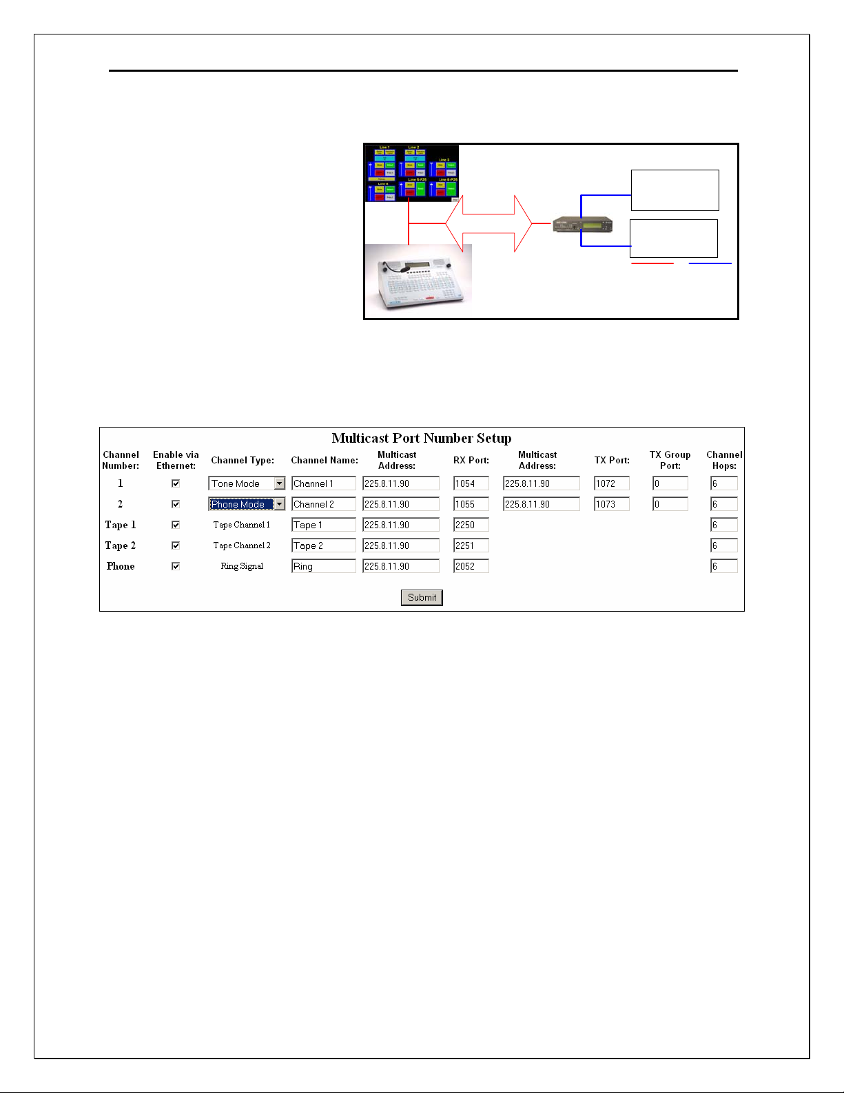
Phone Mode is selected in the Multicast Setup Screen of the IP-223. See Figure 1.
Note, Phone Mode is only available in IP-223 Software Versions 1.08 and higher. Caller ID
demodulation is only available in IP-223 Software Versions 1.10 or higher and PIB223
hardware assembly 880158 rev A.
PIB223 to
PSTN
PIB223 to
PSTN
nalogIP Network
Figure 1 Multicast Setup Screen IP-223 Showing Phone Mode Setup
Each line has a pull down menu that allows selection of phone mode. The multicast address and
port numbers are configured just as any other mode, with the exception of the ring signal. The
ringing signal is broadcast on a unique multicast address. The ringing signal broadcast must be
known to all listening consoles, therefore, make sure the configuration for the ring multicast and
port numbers are consistent on the IP-223 and any listening console. For console configurations,
please refer to the specific User Manual for that product.
2 Front and Rear Panel Connections
2.1 Front Panel LED’s
POWER: Green LED indicates power to the PIB223.
RING: Red LED indicates Ring.
OFFHOOK: Red LED indicates the IP-223 has taken the PIB223 offhook.
Page 5
IP223 Phone Interface Box 3
2.2 Rear Panel Connectors
POWER: There are two power connectors. First the 3.5mm center positive barrel type.
Second, the two-pin screw lug type. Both inputs accept a voltage range of 12-16
VDC. There is an additional Ground lug for chassis ground connections.
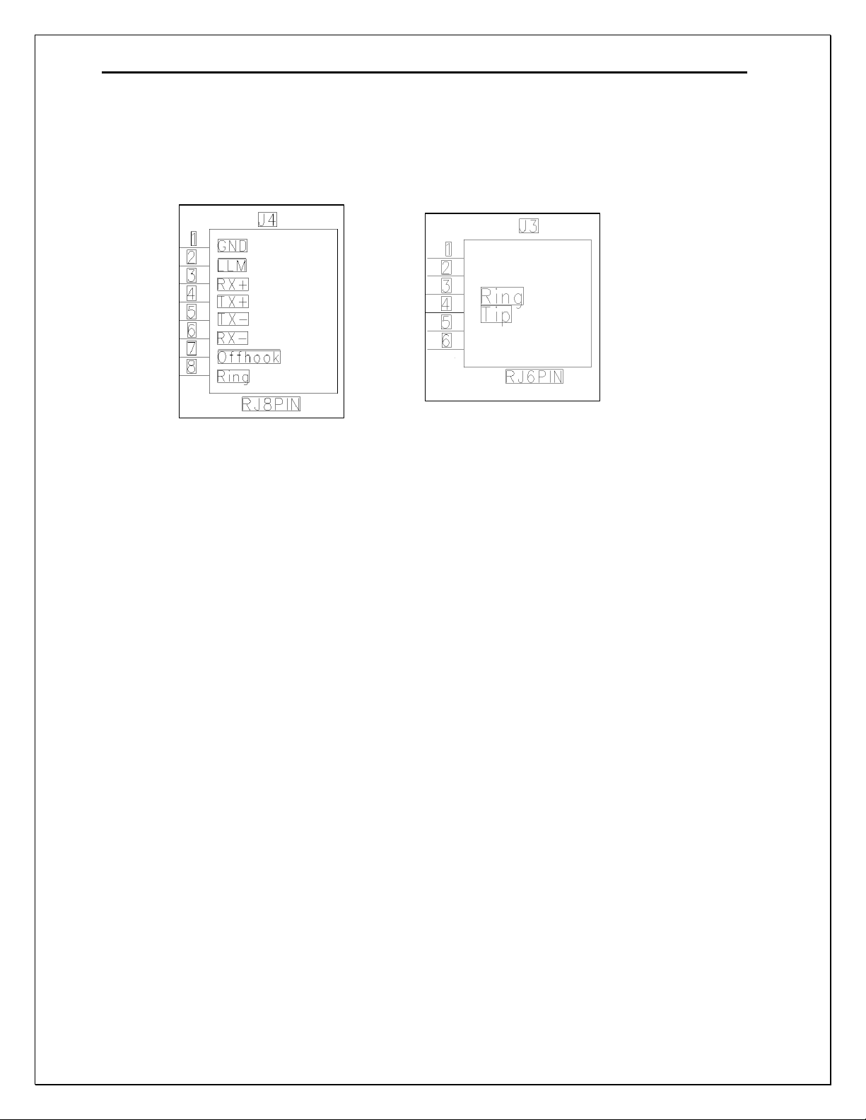
4W LINE: Connector J4
Ground: PIB223 Ground connection.
LLM: The local loop monitor detects a cut line or a parallel phone offhook.
Rx/Tx: 4 wire audio pairs connected to the IP-223.
Offhook: An input the IP-223 uses to control offhook status to the PSTN.
Ring: An output to indicate to the IP-223 that the line is ringing.
PHONE: Connector J3
Tip and Ring: Standard two wire PSTN connections. All signaling and audio is present
on the Tip and Ring pair.
3 PIB223 Setup and Alignment Procedure
3.1 IP-223 Setup
3.1.1 Jumper Settings
Jumper position Connection Type:
“B” Balanced 600 Ohm
Line 1: J3, J9 ,J11, J16, J21
Line 2: J25, J28, J29, J19, J20
“A” 600 Ohm Rx Termination
Line 1: J14
Line 2: J24
3.1.2 Web Page Configuration
Figure 2 shows the Multicast setup page. This is the location that Phone mode is initially
configured via the pull down menu for Channel Type. It must be done first to allow the Phone
Page 6

4 PIB223
Setup page to be displayed. In Phone Mode, the Multicast address is not important, as the
Console will connect via TCP/IP socket. Make sure that the Rx and Tx port numbers are unique.
The ring signal must be unique Multicast and Rx port number from other phone or radio
channels.
Figure 3 shows the general setup for Phone mode operation. Relays, timeouts and delays are
setup here. Typical LAM levels for Rx audio are –30dB. Again, to view the Phone mode page,
first the Channel Type needs to be set to Phone Mode.
Figure 2 Multicast Setup Page - Phone Mode Configuration
3.1.3 Per Line Setup Page Definitions
TX Delay:
The TX Delay field can be configured from 0 to 1000 milliseconds, it provides for the
ability to delay TX audio for a programmable period.
RX Delay:
The RX Delay field can be configured from 0 to 1000 milliseconds, it provides for the
ability to record and store RX audio for a programmable period.
LAM Settings:
LAM Level is the signal level the audio must exceed, in dbm, to trigger the RX indication
and packet generation to the console. LAM Time is the time the RX indication and the
packet generation will continue after the LAM level threshold is exceeded.
Relay Closure:
Selecting check box labeled R1 will cause the R1 relay to energize during the Ring
cadence. Selecting check box labeled R2 will cause the R2 relay to energize when the
phone is taken off-hook.
Auto Answer: This feature is used to remotely connect to the IP223/PIB223
The IP223 will automatically answer the phone after the number of rings entered into this
field.
Page 7

IP223 Phone Interface Box 5
Auto Disconnect Time:
If the LAM level threshold is not exceeded after the Auto Disconnect time has expired, the
IP223 will automatically place the PIB223 On-hook or disconnect.
Star – Pound Keying:
Checking this box will enable an inbound caller on the phone line the capability to control
a radio connected to the opposite line of the IP223. Used in conjunction with Auto Answer
and Auto Disconnect, Star-Pound Keying allows a user to key and de-key the radio. Star
will key the radio. Pound will de-key the radio.
Network Call Timeout:
Network Call Timeout is a global call time out, used to disconnect a network call after the
prescribed time.
Hook Flash Time:
Hook Flash Time temporarily places the line on hook then returns the line to the off hook
condition. The flash time is selectable from 0 – 9999 msec.
Serial Port Parameters: Not used in Phone mode.
Figure 3 Phone Line Setup Page
3.2 C-Soft Setup
NOTE: This example shows a basic setup for C-Soft. Please refer to the User manual for other
Vega IP based consoles if necessary.
Page 8

6 PIB223
3.2.1 Setup IP Multicast List
Figure 4 Setup IP Multicast List - Phone Mode Configuration
Figure 4 shows an example of setting two lines in Phone mode. In this example, the Line Type is
selected as Phone mode. The Line Name is arbitrary and called Line 31 and Line 32 in the case.
The Rx port numbers need to be unique, typically they are just the next number in a standard
assignment sequence. The Base Radio IP address will be the IP address of the IP-223 that is
connected to the PIB223.
3.2.2 Set Global Parameters
Figure 5 Set Global Parameters - Phone Ring Multicast and Port
Figure 5 shows the Phone Ring Multicast and Port number setting. This value will be the same as
that shown in Figure 2.
3.2.3 C-Soft Phone Control Buttons
Figure 6 C-Soft Phone Control Buttons Setup
Page 9

IP223 Phone Interface Box 7
Figure 6 shows a few of the basic C-Soft Phone Control buttons. Any button can be configured
for a task by Right-Clicking on the button, then using the UI Element Function pull down menu.
In this case, Phone – On/Offhook was selected. The Remote Phone Line Select tab shows that no
specific line was selected as the Phone asset. Instead Pool was selected. In the case of the IP-223,
Pool mode means that if both lines are setup as Phone Mode, the open line will be selected for
use when the console tries to connect. This is the same function as the multi-line telephone. Also
shown is an example of a few phone control buttons. Please refer to the C-Soft manual for
further details on the button configuration.
3.3 Audio Alignment Procedure
Audio alignment is done in two steps. First the Rx path is aligned, then Tx. The IP-223 has front
panel alignment features for both Rx and Tx. Using the front panel buttons on the IP-223, press
and hold the LINE button, then press IC.
While continuing to hold the LINE, repeated presses of the IC will step through several features,
including the alignment features.
LINE/IC first: IP and Subnet mask addresses
LINE/IC Second: Tx Alignment. (note, the lines that are in phone mode will display the
return echo loss value used in this alignment)
LINE/IC third: Receive audio signal levels are measured at the DSP level.
LINE/IC fourth: Reset screen to normal mode.
3.3.1 Receive Audio Alignment
Enter the Receive alignment mode on the IP-223 by Pressing and Holding the LINE button, then
successively pressing and releasing the IC button three times. The PIB223 must be connected to
a live PSTN phone line and then taken off-hook. This can be done with C-Soft, or any IP based
Vega Console. Figure 7 Shows the Receive alignment under way. In this example, C-Soft is
being used as shown in Figure 6.
These are the steps:
1) In C-Soft, press Phone On-hook, the On-hook toggles to off-hook and dial tone is present.
2) Adjust the dial tone level seen by the IP-223 to –12 or –13 dB. (Line1/R175, Line2/R110)
3) Press the Phone Off-hook button, it will toggle to On-hook and the dial tone will cease.
Figure 7 Receive Alignment Procedure.
Page 10

8 PIB223
3.3.2 Transmit Audio Alignment
Enter the transmit alignment mode on the IP-223 by Pressing and Holding the LINE button, then
successively pressing and releasing the IC button two times. This will display the Tx alignment
feature of the IP-223 shown in Figure 8. A 1kHz tone is generated by the IP-223 that is used to
measure the echo return loss from the PIB223.
These are the steps:
1) Turn off the Tx alignment feature (if already turned on).
2) In C-Soft, press Phone On-hook, the On-hook toggles to off-hook and dial tone is present.
3) Dial a known number and initiate a call. When the call is answered, maintain a quiet line.
4) Turn on the Tx alignment feature. Adjust the Tx POT so –23 or –24dB is read on the display.
5) Press the Phone Off-hook button, it will toggle to On-hook and the call will cease.
Figure 8 Transmit Audio Alignment Procedure.
Using LINE and IC, return the IP-223 to normal mode.
The IP-223 and PIB223 are ready for use.
Page 11

IP223 Phone Interface Box 9
4 Assemblies: PIB223 and Cabling
Page 12

10 PIB223
5 Warranty, Service, Repair, and Comments
Important! Be sure the exact return address and a description of the problem or
work to be done are enclosed with your equipment.
Warranty (Limited)
All Telex Communications, Inc. manufactured Vega Signaling products are guaranteed against
malfunction due to defects in materials and workmanship for three years, beginning at the date of original
purchase. If such a malfunction occurs, the product will be repaired or replaced (at our option) without
charge during the three-year period, if delivered to the Telex factory. Warranty does not extend to
damage due to improper repairs, finish or appearance items, or malfunction due to abuse or operation
under other than the specified conditions, nor does it extend to incidental or consequential damages.
Some states do not allow the exclusion or limitation of incidental or consequential damages, so the above
limitation may not apply to you. This warranty gives the customer specific legal rights, and there may be
other rights which vary from state to state.
Factory Service Center
TELEX Communications, Inc.
Vega Signaling Products
8601 East Cornhusker Highway, Lincoln, Nebraska, 68507
Phone: (402) 465-7026 / (800) 752-7560 Fax: (402) 467-3279
E-mail: vega@telex.com, Web: www.vega-signaling.com
Claims
No liability will be accepted for damages directly or indirectly arising from the use of our materials or from
any other causes. Our liability shall be expressly limited to replacement or repair of defective materials.
Suggestions or Comments
We’d appreciate your input. Please send us your suggestions or comments concerning this manual, by
fax (402-467-3279) or e-mail them to
: vega@telex.com
Visit our web site at www.vega-signaling.com
Technical Support:
email address: acttechsupport@us.telex.com
phone #: 1-800-898-6723
Page 13

IP223 Phone Interface Box 11
6 PIB223 Specifications
Operating Temperature Range: 0 to 55°C for full
specifications
Power Requirements: +12 to +16 Vdc, semi-regulated,
700ma.
Frequency Response: ±1.5 dB, 300 to 3000 Hz
Audio Distortion: 2% THD maximum
Dimensions: 2 ¾ ” Wide, 4 ¾ ” Deep, by 1 ¾ ” High
Front panel operations:
LED’s:
Power Indication
Offhook Status
Ring Indication
Rear Panel Connections:
Dual 12-16VDC power receptacles.
RJ45 – 4W connection to IP-223.
RJ12 – Phone Line interface.
Options:
19 inch rack mount kit, can accommodate 4
PIB223 Phone Interface Boxes.
Specifications are subject to change without notice
Page 14

Page 15

TELEX Communications, Inc.
Vega Signaling Products
8601 East Cornhusker Highway, Lincoln, Nebraska, 68507
Phone: (402) 465-7026 / (800) 752-7560 Fax: (402) 467-3279
E-mail: vega@telex.com, Web: www.vega-signaling.com
 Loading...