

Page 1
Supplementary instructions
Bypass for continuous level
measurement of liquids
VEGAPASS 81
Document ID: 42749
Page 2

Contents
Contents
1 Product description
2 Mounting
3 Supplement
3.1 Technical data .................................................................... 8
3.2 Dimensions ...................................................................... 11
42749-EN-130227
Editing status: 2013-01-29
2
VEGAPASS 81 •
Page 3
Features and ttings of
the bypass tube
1 Product description
1 Product description
The VEGAPASS 81 is a bypass (reference vessel) for use in combination with a continuous level measuring instrument or a point level
sensor.
Depending on the process pressure or process temperature, the
bypass tube can be used in combination with e.g. the VEGAFLEX 81
or VEGAFLEX 86 sensors.
1
C
ersions
V
B
100 %
D
M
0 %
B
2
E
3
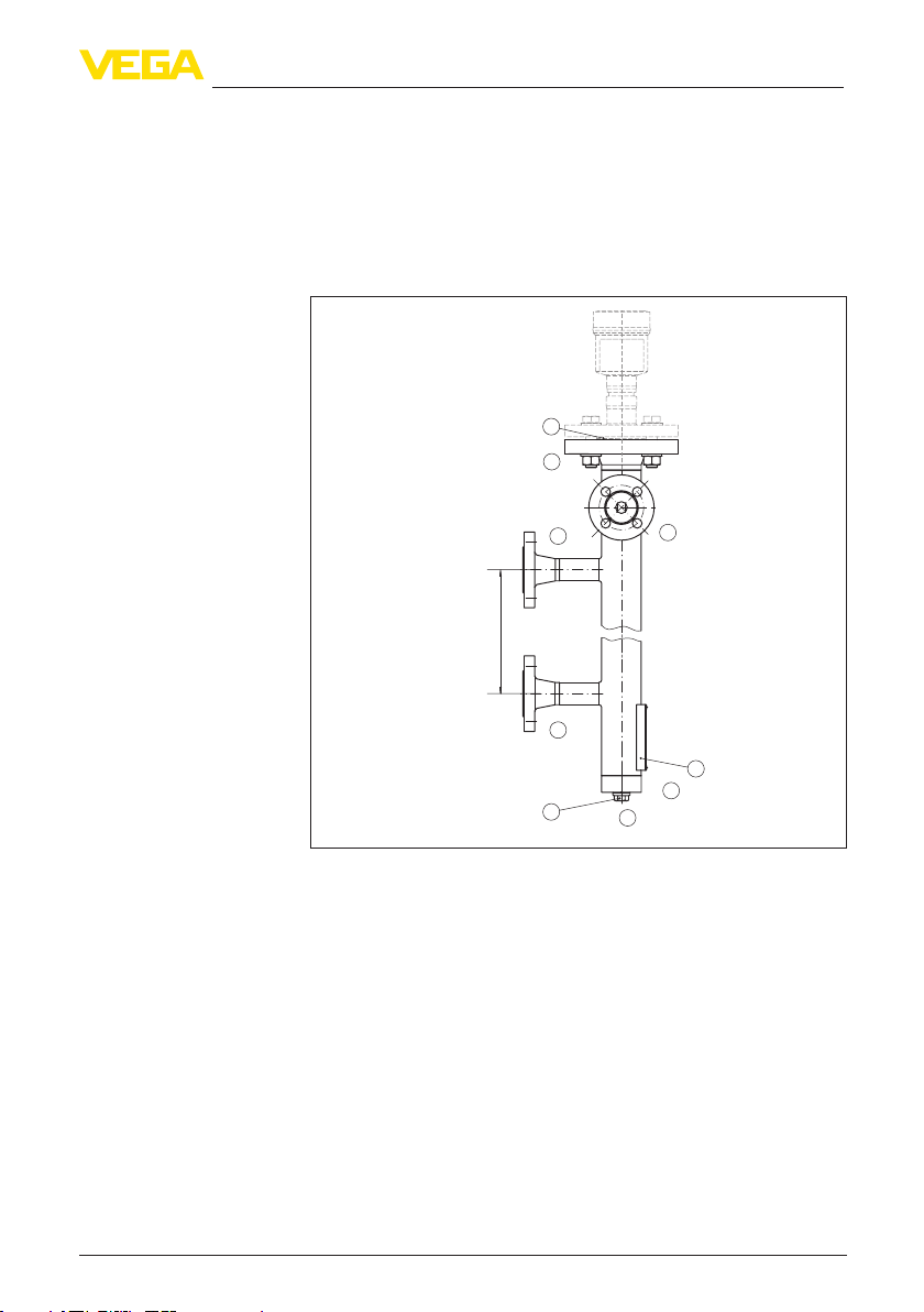
Fig. 1: Typical conguration of VEGAPASS 81 with integrated VEGAFLEX
1 Seal - measuring instrument ange
2 Type plate
3 Closure rinsing connection, e.g. blind plug
B Vessel connection top/bottom
C Measuring instrument ange
D Ventilation connection (optional)
E Chamber closing
F Rinsing connection
M Dimension: Pipe center to pipe center
F
The following versions are possible:
42749-EN-130227
VEGAPASS 81 •
3
Page 4
1 Product description
XX
1 2 3
C
X
C
C
D D D
200mm (7.87")
B
M
B
100mm (3.94")
E
F
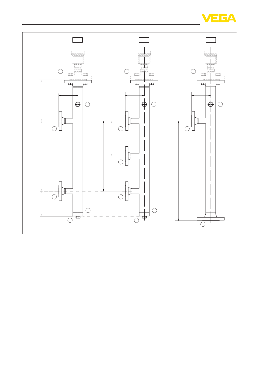
Fig. 2: Versions VEGAPASS 81 - Part 1
1 Version: Side - Side (two connections)
2 Version: Side - Side - Side (three connections)
3 Version: Side - Bottom (two connections)
B Vessel connection top/bottom
C Measuring instrument ange
D Ventilation connection (optional)
E Chamber closing
F Rinsing connection
M Dimensions: tube center to tube center, 300 … 4000 mm (11.8 … 157.5 in)
M1 Dimensions: tube centre to tube center (center connection), 300 … 3700 mm (11.8 … 145.7 in)
L Dimensions: tube center to ange surface, 300 … 4000 mm (11.8 … 157.5 in)
X Dimensions: length tube center to connection ange, 150 … 400 mm (5.91 … 15.75 in)
B
M1
M
B
B
L
B
E
F
B
42749-EN-130227
4
VEGAPASS 81 •
Page 5

1 Product description
4 5 6
C
C
B
B
D D D
200mm (7.87")
200mm (7.87")
B
X
L
L
Y
Y
L
X
B
B
E
100mm (3.94")
F
E
F
B
100mm (3.94")
Fig. 3: Versions VEGAPASS 81 - Part 2
4 Version: Side - Side bottom (two connections)
5 Version: Side top - Side (two connections)
6 Version: Side top - Side bottom (two connections)
B Vessel connection top/bottom
C Measuring instrument ange
D Ventilation connection (optional)
E Chamber closing
F Rinsing connection
L Dimensions tube centre: to ange surface, 300 … 4000 mm (11.8 … 157.5 in)
X Dimensions: length tube centre to connection ange, 150 … 400 mm (5.91 … 15.75 in)
Y Dimension: length pipe centre to pipe centre
C
200mm (7.87")
Y
Y
E
100mm (3.94")
F
42749-EN-130227
VEGAPASS 81 •
5
Page 6

1 Product description
1 2 3
C
D
200mm (7.87")
(5.91")
150mm
C
BB
Fig. 4: Possible ventilation connections (D)
1 Ventilation connection - Flange
2 Ventilation connection - thread G½ or ½ NPT (internal thread)
3 Ventilation connection - thread G¾ or ¾ NPT (internal thread)
B Vessel connection top/bottom
C Measuring instrument ange
D Ventilation connection (optional)
C
D
D
B
42749-EN-130227
6
VEGAPASS 81 •
Page 7

Operating instructions
2 Mounting
2 Mounting
Also take note of the operation instructions of the level or point level
sensor.
Seals
Close openings
V
essel pressure test
Centering
The seals for the vessel connections (B) and the ventilation tting
(optional) must be provided by the customer.
The seals for the measuring instrument ange (C) and the rinsing
connection (F) are already attached to the shipment. You can nd the
seal materials in chapter "Technical data".
Before use, check if the seal material is resistant against the medium,
the process pressure and the process temperature.
The max. permissible pressure of the sensor is specied in the operating instructions manual of the sensor in chapter "Technical data" or
on the type label of the sensor.
Close all emptying and rinsing connections before the setup of VEGAPASS 81. Check if all connections of VEGAPASS 81 are tight.
An assembled bypass tube must be integrated in a probably neces-
sary pressure test of the vessel. Keep the pressure specication of
the type plate in mind.
Avoid contact of the probe with the vessel wall.
For sensors with rod probes use one or several spacers and for sensors with cable probes a centering weight or a spacer on the gravity
weight.
42749-EN-130227
VEGAPASS 81 •
7
Page 8

3 Supplement
3 Supplement
3.1 Technical data
General data
Take note of the information in the operating instructions manual of the installed level sensor
Material 316L corresponds to 1.4404 or 1.4435
Materials
Ʋ Bypass tube 316L/CS (ASTM A105, A106)
Ʋ Spacer ≤ 250 °C PEEK
Ʋ Spacer > 250 °C (optional) StSt (1.4568/AISI 631)
Seal - measuring instrument ange
Ʋ max. 250 °C/40 bar (482 °F/580 psig) Klingersil C-4500
Ʋ max. 400 °C/40 bar (752 °F/580 psig) Graphite
Ʋ max. 400 °C/100 bar
Convex B45A graphite laminate
(752 °F/1450 psig)
Ʋ > 400 °C/> 100 bar
RJF seal rings
(> 752 °F/> 1450 psig)
Tube diameter (outer)
Ʋ Version 2" ø 60.3 mm (2.37 in)
Ʋ Version 3" ø 88.9 mm (3.5 in)
Wall thickness 2 … 11,13 mm (0.079 … 0.438 in)
Process temperature max. 450 °C (842 °F) - see process tting connection
ange (B)
Process pressure
Ʋ Standard version see process tting - connection ange (B)
Ʋ According to pressure device directive
max. 90 bar (1305 psig) - Cat. III, Fluid group I
(PED)
Ʋ According to ASME directive max. 205 bar (2973 psig)
1)
Process tting - connection ange top/bottom (B)
Process pressure in bar (psig) depending on the process temperature
Pressure-Temperature-Assignment - DIN anges
Material 316L (1.4404)
Pressure
range
PN 40 37.9 bar 34.4 bar 31.8 bar 29.9 bar 27.6 bar 26.4 bar 25.7 bar 25.0 bar
PN 63 59.7 bar 54.3 bar 50.1 bar 47.1 bar 43.5 bar 41.7 bar 40.5 bar 39.4 bar
PN 100 94.7 bar 86.1 bar 79.5 bar 74.7 bar 69.0 bar 66.1 bar 64.2 bar 62.6 bar
1)
CS = Carbon steel
8
100 °C 150 °C 200 °C 250 °C 300 °C 350 °C 400 °C 450 °C
VEGAPASS 81 •
42749-EN-130227
Page 9

3 Supplement
Pressure-Temperature-Assignment - ASME anges
Material 316L (1.4404)
Temperature range Class 150 Class 300 Class 400 Class 600 Class 900 Class
1500
-29 … +38 °C 15.9 bar 41.1 bar 55.2 bar 82.7 bar 124.1 bar 206.8 bar 344.7 bar
50 °C 15.3 bar 40.0 bar 53.4 bar 80.0 bar 120.1 bar 200.1 bar 333.5 bar
100 °C 13.3 bar 34.8 bar 46.4 bar 69.6 bar 104.4 bar 173.9 bar 289.9 bar
150 °C 12.0 bar 31.4 bar 41.9 bar 62.8 bar 94.2 bar 157.0 bar 261.6 bar
200 °C 11.2 bar 29.2 bar 38.9 bar 58.3 bar 87.5 bar 145.8 bar 243.0 bar
250 °C 10.5 bar 27.5 bar 36.6 bar 54.9 bar 82.4 bar 137.3 bar 228.9 bar
300 °C 10.0 bar 26.1 bar 34.8 bar 52.1 bar 78.2 bar 130.3 bar 217.2 bar
325 °C 9.3 bar 25.5 bar 34.0 bar 51.0 bar 76.4 bar 127.4 bar 212.3 bar
350 °C 8.4 bar 25.1 bar 33.4 bar 50.1 bar 75.2 bar 125.4 bar 208.9 bar
375 °C 7.4 bar 24.8 bar 33.0 bar 49.5 bar 74.3 bar 123.8 bar 206.3 bar
400 °C 6.5 bar 24.3 bar 32.4 bar 48.6 bar 72.9 bar 121.5 bar 202.5 bar
425 °C 5.5 bar 23.9 bar 31.8 bar 47.7 bar 71.6 bar 119.3 bar 198.8 bar
450 °C 4.6 bar 23.4 bar 31.2 bar 46.8 bar 70.2 bar 117.1 bar 195.1 bar
Tab. 2: ASME B16.5-2003
Class
2500
Pressure-Temperature-Assignment - ASME anges
Material A105
Temperature range Class 150 Class 300 Class 400 Class 600 Class 900 Class
1500
-29 … +38 °C 19.6 bar 51.1 bar 68.1 bar 102.1 bar 153.2 bar 255.3 bar 425.5 bar
50 °C 19.2 bar 50.1 bar 66.8 bar 100.2 bar 150.4 bar 250.6 bar 417.7 bar
100 °C 17.7 bar 46.6 bar 62.1 bar 93.2 bar 139.8 bar 233.0 bar 388.3 bar
150 °C 15.8 bar 45.1 bar 60.1 bar 90.2 bar 135.2 bar 225.4 bar 375.6 bar
200 °C 13.8 bar 43.8 bar 58.4 bar 87.6 bar 131.4 bar 219.0 bar 365.0 bar
250 °C 12.1 bar 41.9 bar 55.9 bar 83.9 bar 125.8 bar 209.7 bar 349.5 bar
300 °C 10.2 bar 39.8 bar 53.1 bar 79.6 bar 119.5 bar 199.1 bar 331.8 bar
325 °C 9.3 bar 38.7 bar 51.6 bar 77.4 bar 116.1 bar 193.6 bar 322.6 bar
350 °C 8.4 bar 37.6 bar 50.1 bar 75.1 bar 112.7 bar 187.8 bar 313.0 bar
375 °C 7.4 bar 36.4 bar 48.5 bar 72.7 bar 109.1 bar 181.8 bar 303.1 bar
400 °C 6.5 bar 34.7 bar 46.3 bar 69.4 bar 104.2 bar 173.6 bar 289.3 bar
425 °C 5.5 bar 28.8 bar 38.4 bar 57.5 bar 86.3 bar 143.8 bar 239.7 bar
450 °C 4.6 bar 23.0 bar 30.7 bar 46.0 bar 69.0 bar 115.0 bar 191.7 bar
Tab. 3: ASME B16.5-2003
Class
2500
42749-EN-130227
VEGAPASS 81 •
9
Page 10

3 Supplement
ASME anges In the same pressure class (Class) anges of CS steel
can withstand higher pressures than anges of material
316L. Flanges of measuring instruments are often made
of 316L. If VEGAPASS 81 is manufactured of CS steel
(ASTM A106, A106), then you select a ange (316L)
with higher nominal pressure (Class) for the measuring
instrument used.
Note: You will nd a complete overview of the available pro-
cess ttings in the "congurator" on our homepage at
www.vega.com/congurator.
Process tting - Measuring instrument ange (C)
Flange DIN DN 50, DN 80
Flange ASME 2", 3"
Thread G (DIN 3852-A), NPT (ASME B1.20.1)
Ventilation connection (D)
Thread G½ (DIN 3852-A), ½ NPT (ASME B1.20.1)
Thread G¾ (DIN 3852-A), ¾ NPT (ASME B1.20.1)
Flange from DN 15 or ½"
Chamber closing (E)
Tube sheet
Flange DIN DN 50, DN 80 (with blind ange)
Flange ASME 2", 3" (with blind ange)
Process tting - Rinsing air connection (F)
Thread up to G1 (DIN 3852-A), 1 NPT (ASME B1.20.1)
10
42749-EN-130227
VEGAPASS 81 •
Page 11

3.2 Dimensions
100 %
0 %
3 Supplement
1
C
150 mm
(5.91")
B
200 mm (7.87")
D
M
B
100 mm (3.94")
3
150 mm
(5.91")
F
E
ø 88,9 mm
(3.5")
2
ø 60,3 mm
(2.37")
Z
Fig. 5: Bypass tube with VEGAFLEX
1 Seal - measuring instrument ange
2 Type plate
3 Closure rinsing connection, e.g. blind plug
B Vessel connection top/bottom
2)
C Measuring instrument ange
D Ventilation connection (optional)
E Chamber closing
F Rinsing connection
M Dimensions: tube center to tube center, 300 … 4000 mm (11.8 … 157.5 in)
z Length - Ventilation connection (depending on the connection)
2)
The distance to the measuring instrument ange is variable - Standard: 200 mm (7.87 in)
42749-EN-130227
VEGAPASS 81 •
11
Page 12

Printing date:
All statements concerning scope of delivery, application, practical use and operating conditions of the sensors and processing systems correspond to the information
available at the time of printing.
Subject to change without prior notice
© VEGA Grieshaber KG, Schiltach/Germany 2013
VEGA Grieshaber KG
Am Hohenstein 113
77761 Schiltach
Germany
Phone +49 7836 50-0
Fax +49 7836 50-201
E-mail: info.de@vega.com
www.vega.com
42749-EN-130227
 Loading...