

Page 1
Model NI223
IP-223 iDen Interface
Technical Manual
JUNE 2005 P.N. 804165
Revision A
Page 2

Accessories:
1) iDen Radio DB9 Splitter Cable Assembly, Telex PN (301953)
Page 3

NI223 iDen Radio Interface 1
Table of Contents
1
General ...................................................................................2
2 Front and Rear Panel Connections......................................2
2.1 Front Panel LED.............................................................................................................2
2.2 Rear Panel Connectors....................................................................................................2
3 NI223 Setup and Alignment Procedure ...............................3
3.1 IP-223 Setup.................................................................................................................... 3
3.1.1 Jumper Settings....................................................................................................... 3
3.1.2 Web Page Configuration......................................................................................... 3
3.2 Connecting the IP-223 and the NI223 ............................................................................ 4
3.3 iDen Radio Setup............................................................................................................5
3.4 C-Soft Setup.................................................................................................................... 5
3.4.1 Setup IP Multicast List............................................................................................ 5
3.4.2 Set Global Parameters............................................................................................. 6
3.4.3 C-Soft Phone Control Buttons................................................................................ 6
3.4.4 C-Soft Radio Line Types:....................................................................................... 6
3.5 Audio Alignment Procedure........................................................................................... 8
3.5.1 Receive Audio Alignment....................................................................................... 8
3.5.2 Transmit Audio Alignment..................................................................................... 8
4 Assemblies: NI223 and Cabling ...........................................9
5 Warranty, Service, Repair, and Comments.......................10
6 NI223 Specifications............................................................11
Table of Figures
Figure 1 Multicast Setup Screen IP-223 Showing iDen Radio Setup ............................................ 2
Figure 2 iDen Radio Setup Page..................................................................................................... 4
Figure 3 Connection between IP-223 and NI223 ........................................................................... 4
Figure 4 Setup IP Multicast List – iDen Radio in Phone Mode operation..................................... 5
Figure 5 Setup Global Parameters - Phone Ring Multicast and Port.............................................. 6
Figure 6 C-Soft Phone Control Buttons Setup................................................................................ 6
Figure 7 IP-223 Receive Audio Alignment Example..................................................................... 8
Figure 8 IP-223 Transmit Audio Gain Setup..................................................................................9
Page 4
2 NI223 iDen Radio Interface
A
1 General
The NI223 is an iDen interface box
designed to connect the IP-223
Ethernet Adapter Panel to an iDen
radio phone system, primarily the
Nextel network. The IP-223/NI223
LAN/WAN
combination will make the Nextel
network an IP asset to any
Telex/Vega IP base consoles. (C-Soft,
C-6200, IP-1616 or IP-2002) The IP223 must be placed in iDen Radio
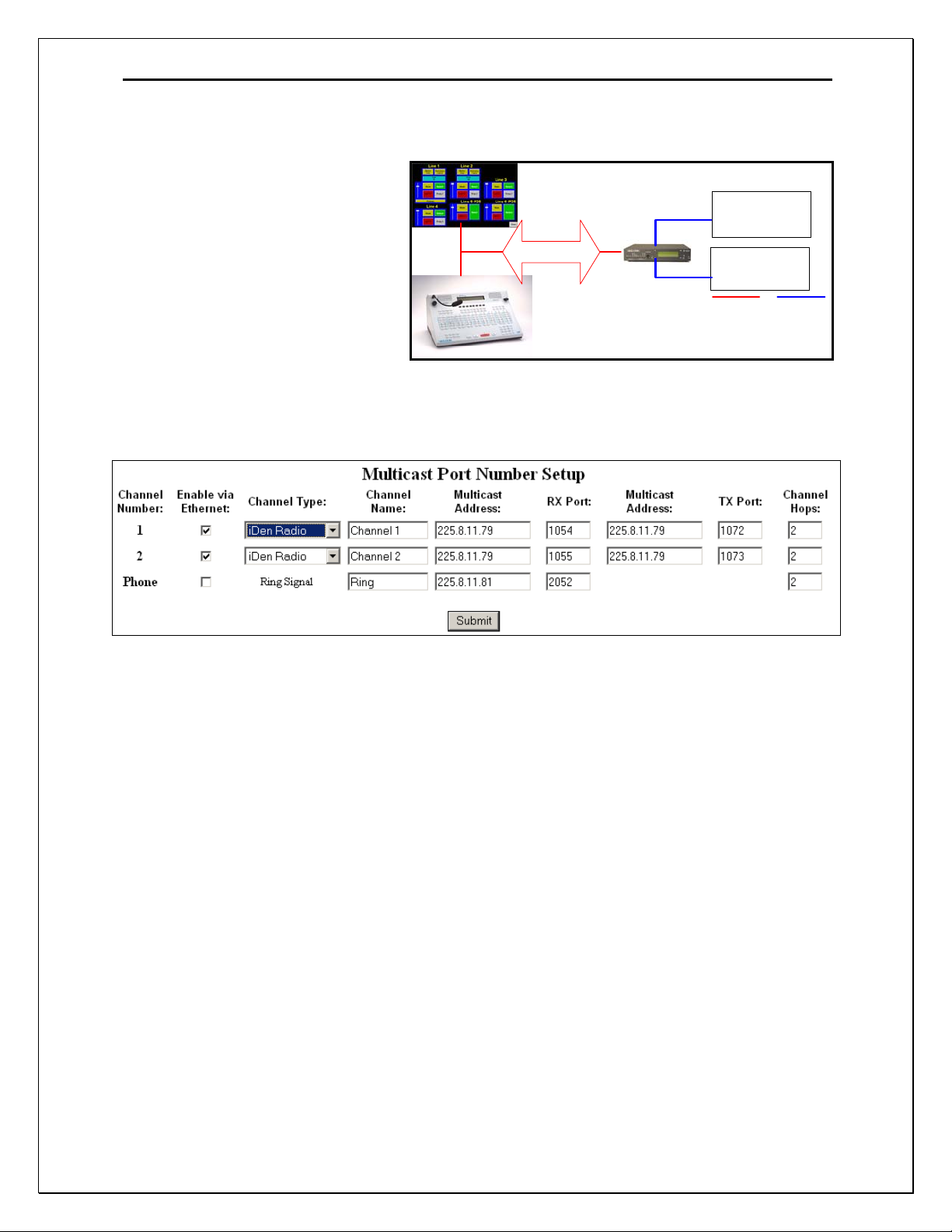
Mode to control the NI223. iDen Radio Mode is selected in the Multicast Setup Screen of the IP-
223. See Figure 1. Note, iDen Radio Mode is only available in IP-223 Software Versions
1.09 and higher.
NI223 to
iDen
NI223 to
iDen
nalogIP Network
Figure 1 Multicast Setup Screen IP-223 Showing iDen Radio Setup
Each line has a pull down menu that allows selection of iDen Radio Mode. The multicast address
and port numbers are configured just as any other mode, with the exception of the ring signal.
Standard phone calls can be made through the iDen interface and the IP223. The ringing signal is
broadcast on a unique multicast address. The ringing signal broadcast must be known to all
listening consoles, therefore, make sure the configuration for the ring multicast and port numbers
are consistent on the IP-223 and any listening console. For console configurations, please refer to
the specific User Manual for that product.
2 Front and Rear Panel Connections
2.1 Front Panel LED
POWER: Green LED indicates power to the NI223.
2.2 Rear Panel Connectors
There is only a single connector on the rear of the NI223. All connections terminate on the
DB25.
Page 5

NI223 iDen Radio Interface 3
Pin # Signal Pin # Signal
1) +12VDC 14) IP223 Ground
2) IP223 Transmit Data 15) MUTE (unused)
3) IP223 Receive Data 16) Option 1 (unused)
4) Option 2 (unused) 17) Radio Transmit Data
5) Radio Receive Data 18) +5VDC
6) Radio Audio IN 19) Radio Audio OUT
7) PTT Relay NO (unused) 20) RTS (unused)
8) Radio DGND 21) CTS
9) Radio Audio GND 22) NC
10) NC 23) NC
11) PTT Relay COM (unused) 24) IP223 RX+
12) IP223 RX- 25) IP223 TX+
13) IP223 TX- Shield Ground
Make sure you connect the Earth Ground to avoid noise issues.
3 NI223 Setup and Alignment Procedure
3.1 IP-223 Setup
3.1.1 Jumper Settings
Jumper position Connection Type:
“B” Balanced 600 Ohm
Line 1: J3, J9 ,J11, J16, J21
Line 2: J25, J28, J29, J19, J20
“A” 600 Ohm Rx Termination
Line 1: J14
Line 2: J24
Serial Port Communications Jumpers: iDen Radio Mode
Line 1: J35 “B”
Line 2: J26 “B”
3.1.2 Web Page C onfiguration
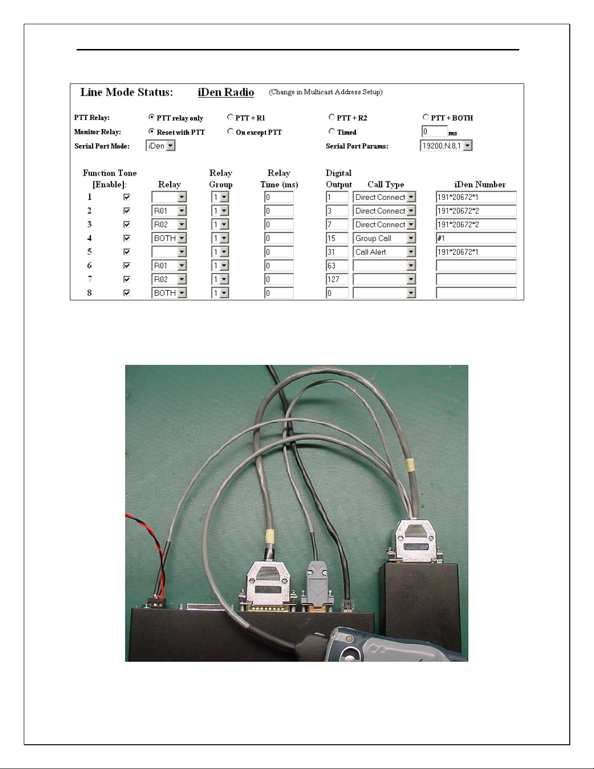
Figure 1 shows the Multicast Setup page. This is the location that iDen Radio Mode is initially
configured via the pull down menu for Channel Type. It must be done first to allow the iDen
Radio Setup page to be displayed. The iDen Radio Interface can be used to make Direct Connect,
Group Call or Alert Calls in a normal radio sense. The multicast fields are setup using normal
radio configurations. Figure 2 shows the iDen Radio Setup page. The right most column holds
the iDen Radio Direct Connect numbers. The number placed in this field will be associated with
a Function tone. When a Console changes to that Function tone and Transmits, that Direct
Connect number will be sent to the iDen Radio and if available, a connection will be made. If
using the iDen Radio interface is used to make a phone call, the multicasts are unused, as a
TCP/IP socket connection is made in the same manner as Phone mode.
Page 6
4 NI223 iDen Radio Interface
Figure 2 iDen Radio Setup Page
3.2 Connecting the IP-223 and the NI223
Figure 3 Connection between IP-223 and NI223
Page 7

NI223 iDen Radio Interface 5
Connect the IP-223 and the NI223 as shown in Figure 3. The power for the NI223 will be
obtained from the same power connector the IP-223 is using. Make sure the polarities are correct
to avoid damaging the units. Figure 3 shows the iDen Radio configured for use with IP-223
Radio 1. Either or both radio ports on the IP-223 could be used. If both ports are used, a DB9
splitter cable is required to route serial channel one and two to their respective NI223’s. This can
be purchased from the factory. Part number: 301953
3.3 iDen Radio Setup
At power up or reset, with the iDen Radio properly connected, the display on the IP223 should
show “iDen” on the line that was enabled, either the top(line 1) or bottom(line 2) of the display.
If after connecting and configuring the IP-223 properly you do not see “iDen” on the display,
you should check the following items:
1) First double check that you have everything connected as described above.
2) Check that the IP-223 did get enabled for iDen Radio mode, then reset.
3) Check that the Jumpers for the serial communications are correctly set.
4) Make sure the baud rate of the radio is set at 19200. This will differ from radio to radio,
but as an example, in the i315: Press the menu button. Then select Settings, then
Advanced, then Baud Rate and finally 19200.
3.4 C-Soft Setup
NOTE: This example shows a basic setup for C-Soft. Please refer to the User manual for other
Vega IP based consoles if necessary.
3.4.1 Setup IP Multicast List
Figure 4 Setup IP Multicast List – iDen Radio in Phone Mode operation
Figure 4 shows an example of setting two lines in Phone mode. In this example, the Line Type is
selected as Phone mode. The Line Name is arbitrary and called Line 31 and Line 32 in the case.
The Rx port numbers need to be unique, typically they are just the next number in a standard
assignment sequence. The Base Radio IP address will be the IP address of the IP-223 that is
connected to the NI223.
Page 8

6 NI223 iDen Radio Interface
3.4.2 Set Global Paramet ers
Figure 5 Setup Global Parameters - Phone Ring Multicast and Port
Figure 5 shows the Phone Ring Multicast and Port number setting. This value will be the same as
that shown in Figure 1.
3.4.3 C-Soft Phone Control Buttons
Figure 6 C-Soft Phone Control Buttons Setup
Figure 6 shows a few of the basic C-Soft Phone Control buttons. Any button can be configured
for a task by Right-Clicking on the button, then using the UI Element Function pull down menu.
In this case, Phone – On/Offhook was selected. The Remote Phone Line Select tab shows that no
specific line was selected as the Phone asset. Instead Pool was selected. In the case of the IP-223,
Pool mode means that if both lines are setup as Phone Mode(PSTN or iDen System), the open
line will be selected for use when the console tries to connect. This is the same function as the
multi-line telephone. Also shown is an example of a few phone control buttons. Please refer to
the C-Soft manual for further details on the button configuration.
3.4.4 C-Soft Radio Line Ty pes:
To use the IP-223 iDen Radio interface in Direct Connect Mode, the line type will be the
standard radio type. As shown in Figure 2, each Function tone entry will have a Direct Connect
number association. Simply changing the Function Tone selection will steer the Direct Connect
dial string. The same can be said for Group Call and Call Alert.
Page 9

NI223 iDen Radio Interface 7
F
3.5 Manual Connections
A DTMF keypad can also be used on the console to manually dial the DirectConnect and Phone
modes of the NI223. By adding a 16 key dtmf keypad to the console design in C-Soft this is
facilitated. One major difference between this keypad and the normal keypad is the addition of
the A,B,C, and D keys for advanced control of the Nextel phone.
3.5.1 A-Key, Alert
The ‘A’ key is used to send an Alert function over the iDen system. Using the standard dialing
keys, enter the ID of the radio to send the alert to and then press the A key. Typically, labeling
the A key as Alert is a good idea.
3.5.2 B-Key, Send
The B key is used as a send button in manually dialing a phone call. Take the phone line
offhook, dial the number, then press the B key to connect the call. Label this button as send in
the console design.
3.5.3 C-Key, Group Call
Enter the group number to be called followed by the C key. When
the PTT button is pressed, a group call will be completed. Label the
C key as Group.
3.5.4 D-Key, DirectConnect Call
Enter the direct connect number to connect to then the D key. When
the PTT button is pressed, a Direct Connect call will be completed.
igure 7 - Manual DTMF key
layout with iDen commands
Page 10

8 NI223 iDen Radio Interface
3.6 Audio Alignment Procedure
3.6.1 Receive Audio Alignment
The standard Receive audio alignment procedures should be followed for the NI223 installation.
With AGC turned OFF, inject a 0dBm test tone into the IP-223 front end and measure the level
at the Receive audio test points for line 1 or 2. (TP13 or TP1) The level should be near, but
below 0dBm reference from the test point to ground (TP14, near TP13). This should result in
audio levels from the iDen Radio at –5dBm to –10dBm as shown in Figure 8. A meter can be
used if the unit is on the bench top, or if installed, the front panel VU meter can be used. To
access the VU meter Press and Hold the line button, then press the IC button three times. A
general talk test is still the best mechanism for ensuring a quality connection. The system can be
tested with a handset from the front panel as well. To purchase the handset, contact the Telex
Vega Sales department.
Figure 8 IP-223 Receive Audio Alignment Example
3.6.2 Transmit Audio Alignment
The Transmit audio (Audio IN) to the iDen Radio should not be overdriven. The levels to the
radio should be at or near -5dBm as measured at the IP-223 radio test point on the front of the
Page 11

NI223 iDen Radio Interface 9
unit. The TX Pot on the front panel of the IP-223 will be near 9-12 o’clock depending on the
microphone source. Alternatively, the Software Gains may be adjusted to gain more granularity
in the pot setting to accommodate different microphones. Figure 9 shows an example Transmit
Gain setting. From here a simple talk test will result in good audio levels.
Figure 9 IP-223 Transmit Audio Gain Setup
4 Assemblies: NI223 and Cabling
Page 12

V
A
A
This drawing, written description or specification Is
a proprietary product of TELEX, Lincoln, NE, and
shall not be released, disclosed, nor duplicated
without the written permission of TELEX.
APPROVALS: DR BY: SBC
DATE: 04/15/2005
CHK: SBC
DATE: 04/15/2005
Telex Communications INC.
Lincoln, Nebraska USA
APPD: HN
DATE: 04/15/2005
PROD: KR
DATE: 04/15/2005
PART NO:
REV LEVEL:
880138
A
TITLE:
RE
RELEASED
PCB ASSY, NI223
REVISIONS
DESCRIPTION ECO NO DATE
41-000202
04/15/05
PPD
HN
LN,BE PAGE 1 OF 3
Page 13

A/R
This drawing, written description or specification Is
a proprietary product of TELEX, Lincoln, NE, and
shall not be released, disclosed, nor duplicated
without the written permission of TELEX.
APPROVALS: DR BY: SBC
DATE: 04/15/2005
CHK: SBC
DATE: 04/15/2005
Telex Communications INC.
Lincoln, Nebraska USA
APPD: HN
DATE: 04/15/2005
PROD: KR
DATE: 04/15/2005
PART NO:
REV LEVEL:
880138
A
TITLE:
ITEM
1
2
3
4
5
6
7
8
9
10
11
12
13
14
15
16
17
18
19
20
21
22
23
24
25
26
PCB ASSY, NI223
TYPE DESCRIPTION PART NO. DESIGNATOR
QTY
NEW
1 CAP 100UF, ELECTROLYTIC,SMT 102884316T C1
2 CAP .001UF 0603 50V +/-10% 102881717T C19 C20
1 CAP 10uf 16vTANT 3528 B 102877065T C2
8 CAP 0805 1UF 10V +/-10% 102881875T C3 C4 C5 C10 C11 C12 C13 C14
12 CAP 220PF 0603 50V +/-5% 723482134T C6 C8 C9 C15 C16 C17 C18 C21 C22 C23 C24 C25
2 CAP 0.1UF 0603 723489101T C7 C26
1 LED RT. ANG. GREEN 1610628 D1
2 DIODE SMT 4004 1A DIODE 760621-4 D3 D4
1 FUSE SMT FUSE WITH HOLDER 7101051 F5
1 FERRITE COMMON MODE FB 724039T FB2
2 FERRITE 0805 FERRITE BEAD 723511T FB3 FB5
1 CONN RT ANGLE DB25-TH 640136 J3
6 RES 10K 0603 1% 723481300T R1 R2 R7 R10 R11 R14
1 RES 15K 0603 5% 723488153T R13
9 RES 0 OHM 0603 5% 723488000T R15 R16 R17 R18 R19 R20 R24 R25 R26
1 RES 0805 1k 1% 102515200T R22
1 RES 21K 0805 1% 102515331T R3
3 RES 100K 0603 1% 723481400T R4 R9 R23
3 RES DNP DNP R5 R12 R21
2 RES 33.2K 0603 1% 723481350T R6 R8
2 XFMR TRAN 600:600 7302831 T1 T2
1 IC PTN78000WAH 511558000 U1
2 IC NE5532 DUAL OP Amp 760268 U2 U4
1 PCB PRINTED CIRCUIT BOARD 750729
x
PASTE SOLDERPASTE BE738
REFERENCE SCHEMATIC 770966
0
LN,BE Page 2 of 3
Page 14

Page 15

770966 rev A.sch-1 - Thu Jun 16 19:10:09 2005
Page 16

Page 17

10 NI223 iDen Radio Interface
5 Warranty, Service, Repair, and Comments
Important! Be sure the exact return address and a description of the problem or
work to be done are enclosed with your equipment.
Warranty (Limited)
All Telex Communications, Inc. manufactured Vega Signaling products are guaranteed against
malfunction due to defects in materials and workmanship for three years, beginning at the date of original
purchase. If such a malfunction occurs, the product will be repaired or replaced (at our option) without
charge during the three-year period, if delivered to the Telex factory. Warranty does not extend to
damage due to improper repairs, finish or appearance items, or malfunction due to abuse or operation
under other than the specified conditions, nor does it extend to incidental or consequential damages.
Some states do not allow the exclusion or limitation of incidental or consequential damages, so the above
limitation may not apply to you. This warranty gives the customer specific legal rights, and there may be
other rights which vary from state to state.
Factory Service Center
TELEX Communications, Inc.
Vega Signaling Products
8601 East Cornhusker Highway, Lincoln, Nebraska, 68507
Phone: (402) 465-7026 / (800) 752-7560 Fax: (402) 467-3279
E-mail: vega@telex.com, Web: www.vega-signaling.com
Claims
No liability will be accepted for damages directly or indirectly arising from the use of our materials or from
any other causes. Our liability shall be expressly limited to replacement or repair of defective materials.
Suggestions or Comments
We’d appreciate your input. Please send us your suggestions or comments concerning this manual, by
fax (402-467-3279) or e-mail them to
: vega@telex.com
Visit our web site at www.vega-signaling.com
Technical Support:
acttechsupport@us.telex.com
phone #: 1-800-898-6723
Page 18

NI223 iDen Radio Interface 11
6 NI223 Specifications
Operating Temperature Range: 0 to 55°C for full
specifications
Power Requirements: +12 to +16 Vdc, semi-regulated,
700ma.
Frequency Response: ±1.5 dB, 300 to 3000 Hz
Audio Distortion: 2% THD maximum
Dimensions: 2 ¾ ” Wide, 4 ¾ ” Deep, by 1 ¾ ” High
Front panel operations:
LED’s:
Power Indication
Rear Panel Connections:
DB25
Earth Ground.
Options:
19 inch rack mount kit, can accommodate 4
NI223 Phone Interface Boxes.
Specifications are subject to change without notice
Page 19

Page 20

TELEX Communications, Inc.
Vega Signaling Products
8601 East Cornhusker Highway, Lincoln, Nebraska, 68507
Phone: (402) 465-7026 / (800) 752-7560 Fax: (402) 467-3279
E-mail: vega@telex.com, Web: www.vega-signaling.com
 Loading...