


Maritime Radio Services Operation
Warning! This transmitter will operate on channels/frequencies that have restricted use in the United States. The channel assignments include frequencies assigned for exclusive use of the U.S. Coast Guard, use in Canada, and use in international waters. Operation on these frequencies without proper authorization is strictly forbidden. For frequencies/ channels that are currently for use in the U.S. without an individual license, please contact the FCC Call Center at 1-888-CALL-FCC.
For individuals requiring a license, such as commercial users, you should obtain a license application from your nearest FCC field office (for US users) or Industry Canada (for Canadian users).
FCC / Industry Canada Information
Certification FCC Part 80 or RSS-182/188 Output Power 1 Watt (low) and 25 Watts (high) Emission 16K0F3E, 16K0F2D
Transmitter Frequency Range 156.025 to 157.425 MHz FCC Identifier AMWUT601
IC Certification Number 513C-UT601D
This device complies with the GMDSS provisions with Part 80 of the FCC Rules, as well as Part 15 of the FCC Rules. Operation is subject to the condition that this device does not cause harmful interference.
Unauthorized changes or modifications to this equipment may void compliance with the FCC Rules. Any change or modification must be approved in writing by Uniden Corporation. Changes or modifications not approved by Uniden could void the user’s authority to operate the equipment.
The cords on this product and/or accessories contain lead, a chemical known to the State of California to cause birth defects or other reproductive harm. Wash hands after handling. Uniden works to reduce lead content in our PVC coated cords in our products and accessories.
Installer Instructions
To connect an optional external antenna to the radio for your WHAM x 4, you will need a 2.4GHz antenna with mounting bracket and a cable with N-type male connectors. Keep the antenna lead-in wire as short as possible.
Follow these steps to connect an optional external antenna to the radio.
1.Use a mounting bracket to mount the antenna on a vertical mast or pole.
2.Run the cable from the antenna to the radio.
3.Attach one end of the cable to the connector lug on the antenna, then connect the other end to the External Antenna Connector jack on the back of the radio.
2 |
Marine Radio Services Operation |

Contents |
|
About Digital Selective Calling ............................................................................ |
5 |
Introduction ........................................................................................................... |
6 |
Feature Highlights ................................................................................................ |
6 |
General Features ............................................................................................. |
6 |
Weather Features ............................................................................................. |
7 |
DSC Features ................................................................................................... |
7 |
Optional Features ............................................................................................. |
8 |
Understanding Your Radio .................................................................................. |
9 |
About This Manual ........................................................................................... |
9 |
How The Radio’s Controls Appear in This Manual ........................................... |
9 |
Controls, Connections, and Indicators .............................................................. |
11 |
Front Panel ....................................................................................................... |
11 |
Rear Panel Connectors .................................................................................... |
11 |
Hailer Connector/Cable .................................................................................... |
12 |
GPS/External Speaker Connector/Cable ......................................................... |
12 |
WHAM Control Unit Connector ........................................................................ |
12 |
Setting Up The Radio ........................................................................................... |
13 |
Connecting the Antenna ................................................................................... |
13 |
Connecting Power ............................................................................................ |
13 |
Installation ........................................................................................................ |
13 |
Using a WHAM or WHAM x 4 Microphone With the Radio .............................. |
15 |
Using One or Two Hailer Horns With the Radio ................................................ |
15 |
A Look at the Radio .......................................................................................... |
16 |
A Look at the Microphone ................................................................................ |
17 |
A Look at the Display ........................................................................................ |
17 |
Basic Operation .................................................................................................... |
18 |
Turning the Radio On and Off .......................................................................... |
18 |
Selecting a Channel ......................................................................................... |
18 |
Transmitting and Receiving .............................................................................. |
18 |
Adjusting the Transmit Power .......................................................................... |
19 |
Using Scan ....................................................................................................... |
19 |
Using All Channel Scan .................................................................................... |
19 |
Using Step ........................................................................................................ |
20 |
Using Hail ......................................................................................................... |
20 |
Using the Intercom ........................................................................................... |
20 |
Using GPS ........................................................................................................ |
21 |
Using Battery Hi/Lo Detect ............................................................................... |
21 |
Using 16/9 TRI ................................................................................................. |
21 |
Using Memory Channel .................................................................................... |
22 |
Scanning Memory Channels ............................................................................ |
22 |
Using Triple Watch ............................................................................................ |
22 |
Contents |
3 |
Using the Scrambler .......................................................................................... |
23 |
Using the Weather Function ............................................................................. |
23 |
Performing a Radio Self Test ............................................................................ |
24 |
DSC Operation ................................................................................................ |
24 |
Sending a DSC Distress Call ............................................................................ |
24 |
Receiving a DSC Distress Call .......................................................................... |
25 |
The Radio Menu Settings for DSC Call and Fog Horn ................................. |
25 |
Using the DSC Call Menu.......................................................................... |
26 |
Setting DSC Call Options ......................................................................... |
30 |
Setting the Fog Horn Options ................................................................... |
31 |
The Setup Screen Options ................................................................................. |
33 |
Using the Initialize Sub Menu............................................................................. |
34 |
Setting Up a User MMSI ........................................................................... |
34 |
Setting the Vessel Type ............................................................................ |
35 |
Setting the Fog Horn Frequency............................................................... |
35 |
Adjusting the Backlight.............................................................................. |
35 |
Adjusting the Key Beep............................................................................. |
35 |
Adjusting the Color Pallet.......................................................................... |
35 |
Setting the Local Time - Time Adjust and Time Entry............................... |
36 |
Using the Radio Sub Menu ................................................................................ |
37 |
Channel Name Settings............................................................................... |
37 |
Setting FIPS Codes ..................................................................................... |
38 |
Disabling Auto Channel Switch.................................................................... |
39 |
Position Reply.............................................................................................. |
39 |
Setting Up a Group MMSI............................................................................ |
39 |
Setting Channel Scan .................................................................................. |
40 |
Setting RX Sensitivity .................................................................................. |
40 |
Displaying Time and Position ...................................................................... |
40 |
Setting the XTRACK Beep Options ................................................................... |
40 |
Using the WHAM and WHAM x 4 Sub Menus .................................................. |
41 |
Using the Hailer Rename Option ...................................................................... |
43 |
Using the Scrambler Menu ................................................................................ |
43 |
Using the WHAM Page Sub Menu..................................................................... |
43 |
Using the Crosstrack (XTRACK) Screen ........................................................... |
43 |
Viewing the Compass Screen............................................................................ |
45 |
Using the Digital Menu....................................................................................... |
46 |
Care and Maintenance .......................................................................................... |
46 |
Frequently Asked Questions ............................................................................... |
46 |
Specifications........................................................................................................ |
47 |
Appendix................................................................................................................ |
50 |
NMEA Operation................................................................................................ |
50 |
Reference Information ....................................................................................... |
51 |
Three Year Limited Warranty ............................................................................... |
59 |
4 |
Contents |

About Digital Selective Calling
Digital Selective Calling
DSC is a technique used by marine radio systems to augment calling the another station by voice. It permits other vessels to be called up by keying in a unique identity number known as the MMSI. It also provides a button that will generate a distress alert identifying the vessel in distress, the nature of the problem and a position derived from an installed, optional Global Positioning Satellite (GPS) device.
The feature was implemented in February 1999 as an integral part of the Global Maritime Distress and Safety System (GMDSS).
Digital Selective Calling (DSC) lets mariners instantly send automatically formatted distress alerts to rescue authorities anywhere in the world. Digital selective calling also lets mariners initiate or receive distress, urgency, safety and routine radiotelephone calls to or from any similarly equipped vessel or shore station, without requiring either party to be near a radio loudspeaker. DSC acts like the dial and bell of a telephone, allowing you to “direct dial” and “ring” other radios, or allow others to “ring” you, without having to listen to a speaker.
Your radio's DSC Call feature lets you transmit and receive DSC Calls based on ITU-R M.493-11. For a detailed discussion of this standard, you can refer to the following web site document: http://www.gmdss.com.au/ITU%20DSC%20tech%20spec.pdf and read a full explanation on line.
If you have an optional GPS installed, you can send a distress message in an emergency situation which includes your position. You can also send and receive position data to and from other vessels. Additionally, you can set up and use a directory of other vessels with DSC radios.
The radio's NMEA input and output feature lets you display and use vessel
information. When equipped with an optional GPS, the UM625c can send and receive DSC calls that include the following information: distress, individual, individual ack(nowledgement), all ships, group, position request, position reply, and position send. DSC calls to your radio can receive include distress ack, geographic, distress relay, and distress relay ack.
Mobile Maritime Service Identity (MMSI)
This refers to a unique nine digit identification number designated for each qualified vessel or shore station. It is in a way, a maritime equivalent of a telephone number. You must obtain your personal MMSI before you can program and or transmit data mentioned above. If you have access to the web, open either http://www.boatus.com and navigate to the convenient MMSI application form provided. Or, go to http://www.seatow/boatingsafety/mmsi/mmsiRegister.asp and complete the on-line form provided. If you do not have web access, you can call, toll free, BoatUS, in Alexandra, VA at 1-800 563-1536 and request that the MMSI form be mailed or faxed to you. This presumes you use a recreational vessel in domestic U.S. waters and that you are not otherwise required to be licensed. Because BoatUS is set up to take advantage of an electronic registration system, using standard mail or fax will be much slower. You can also call the FCC Forms Distribution Center at 1-800 418-3676 who then will provide you with the form types they require.
About Digital Selective Calling |
5 |

Introduction
Your Uniden UM625c Marine Radio combines state-of-the-art technology with rugged durability and ease of use. The radio's all solid-state design and conservatively-rated components and materials make it an ideal choice for harsh marine environments. The radio's large color display and backlit control buttons make it easy to use even in extreme lighting and weather conditions.
The radio's memory channel scan feature lets you set it so it quickly scans and tunes only the channels you select. The Triple Watch feature lets you easily scan Coast Guard calling, hailing, and distress channels along with any channel you want, and you can tune Coast Guard calling, hailing, and distress channels by pressing a single button. The weather alert features let you monitor weather alert broadcasts and even sound an audible alarm if bad weather is reported in an area you specify.
You can connect an optional GPS module to the radio to help keep track of your current location with space-age precision. You can connect and use a wide variety of optional equipment with the radio, including an FMB321 flush mount, 2 hailer horns, GPS module, wireless microphones, and a plotter. You can connect and use up to two WHAM or four WHAM x 4 wireless microphones with the radio, making onboard communications as flexible as you need them to be. You can even install an optional scrambler board in the radio letting you communicate privately with other vessels that have a scrambler installed.
You should read the rest of this Operating Guide thoroughly to acquaint yourself with all of your radio's features and functions. Save your receipt as proof-of-purchase in case you need to obtain warranty service. Features, specifications, and availability of optional accessories are all subject to change without notice.
Note: Your radio meets the stringent JIS7 waterproof specification. This means that the radio and microphone can be submerged to a depth of 1 meter for up to 30 minutes without incurring damage.
Feature Highlights
General Features
Channel Scan - You can set the radio so it scans only the channels you select or all channels.
Triple Watch - The radio lets you scan Coast Guard/Distress/Hailing Channel 16, secondary Coast Guard/Distress/Hailing Channel 9, and the currently selected channel in order.
Memory Channel Step - You can set the radio so it quickly tunes channels saved in the radio's memory.
Help Screen - The radio has help information built into it, making it easy to find out about any of the radio’s features or operations.
Demo Mode - In RADIO mode, press and hold MENU and HI-LO at the same time. The radio’s automatic demo mode starts. Do nothing further while the demonstration runs. To exit the demo, press and hold MENU and HI-LO again.
6 |
Introduction — Feature Highlights |
One-Touch Emergency Channel - You can quickly tune the radio to Coast Guard/Distress/ Hailing Channel 16 and secondary Coast Guard/Distress/Hailing Channel 9 by pressing a single button.
Hi/Lo Transmit Power - You can set the radio's transmit power to 25 watts or 1 watt.
Channel Mode - You can set the radio's channel mode to USA, INT (international), or CAN (Canada).
Automatic and Manual Display Backlight Adjustment - The display automatically sets its brightness for day or night operation, to make it easier to see in extreme conditions. You can also manually adjust the backlight.
LCD Color Adjustment - You can adjust the LCD colors on the display to let you see them easier at night.
Key Beep Adjustment - You can adjust the volume of the tone you hear when you press a key.
Self Test - The radio automatically tests its hardware and displays the test results.
Channel Name - Lets you change the channel name that appears when you tune a channel.
Auto Position Reply Disable - You can set the radio so when it receives a position request call, it does not automatically reply with your current position.
Attenuator - You can set the radio so it attenuates (reduces) reception of strong signals.
Standby - You can set the radio to its unattended mode.
Receive Log - You can view the receive log, making it easy to see when somebody calls your vessel.
Weather Features
WX Alert Decode Mode - You can set your radio to monitor a selected weather radio channel for weather emergency signals or SAME (Specific Area Message Encoding) alerts for areas you specify. This lets you receive early warning when bad weather is in the area or a national, regional, or local emergency has been detected.
FIPS Code Programming - You can program your radio with up to 30 FIPS (Federal Information Processing Standard) codes for the areas you desire. If the radio receives a SAME alert tone, it checks it against the FIPS codes you programmed and alerts you if it finds a match.
DSC Features
DSC Call - You can use the radio to transmit and receive DSC Call information. See “Using the DSC Call Menu” on Page 26 for more information.
DSC Directory - You can set up a directory of other vessels that have a DSC-capable radio with a Maritime Mobile Service Identity (MMSI) number.
Auto Channel Switch Disable - You can set the radio so it does not automatically change the working channel when it receives a DSC Call. The radio automatically sends a signal to
Feature Highlights |
7 |
the calling vessel that shows that your vessel's radio is unattended, and does not tune to the requested channel.
Optional Features
Scrambler - Install an optional scrambler board in the radio, so you can set the radio to scramble your voice when you transmit, helping you avoid being overheard by other vessels.
Hailer Features - You can use these features if you connect one or two optional hail horns to the radio.
•Loud Hailer - You can use the radio to talk and listen using the speaker.
•Fog Horn - You can use the radio to sound a fog horn. If you connect an optional GPS receiver to the radio, the radio can even sound the appropriate fog horn sound based on the type of vessel where the radio is installed (sail, power, or tow), and whether the vessel is moving or stopped.
GPS Features - You can use these features if you connect an optional GPS receiver to the radio.
•GPS Intuitive - The radio automatically suggests the correct channel mode based on its current location (USA, International, and Canadian channels).
•Automatic Local Time Setting - The radio sets itself to the correct local time.
•Automatic Fog Horn - The radio sounds the appropriate fog horn sound based on the type of vessel where the radio is installed (sail, power, or tow), and whether the vessel is moving or stopped.
•NMEA Input - Connect an optional GPS receiver to the radio, to display
information such as your vessel's latitude and longitude, speed and course, and the date and time. You can also send position information and use GPS Intuitive data using this feature.
•NMEA Output - The radio automatically passes received DSC information to an optional connected chart plotter.
WHAM Input - If you connect up to two optional 900 MHz analog WHAM microphones to the radio, you can use it to control the radio from almost anywhere aboard your vessel.
WHAM x 4 Input - Connect up to four optional 2.4 GHz digital WHAM x 4 microphones to the radio, that you can use it to control the radio from almost anywhere aboard your vessel, and each WHAM x 4 user can communicate with another WHAM x 4 user. You can also use the radio's intercom function to communicate with each WHAM x 4 user. You can even use a second base radio as an intercom.
8 |
Feature Highlights |

Understanding Your Radio
About This Manual
The screen displays used in this manual are representations of what might appear when you use your radio. Since what you see depends on the frequencies for your area and the settings you select, you might notice some differences between what is in this manual and what appears on your radio's display. Buttons you press appear in BOLD type, icons that
appear on the display appear in BOLD REVERSED type, and text that appears on the display appears in italic type.
How The Radio’s Controls Appear in This Manual
To help navigate the radio's menus, the steps shown in this manual describe the displays you see and the keys you press or control you operate to get a desired result.
This example shows you how to use the radio's menu to program a user MMSI for the first time. The MMSI is a unique nine digit identification number allocated to each vessel or shore
station. It is analagous to a normal telephone number. This example shows you the button to press (PUSH/SELECT) to view a series of choices, the control to use (PUSH/SELECT) to view and select more choices, and the correct options to select (SETUP and USER MMSI) as you rotate PUSH/SELECT. It also instructs you to press PUSH/SELECT to select the options.
Important: If you have already set the user MMSI, DO NOT CHANGE IT unless you have received a new user MMSI. After you program a user MMSI for the first time, you can only change it once more. If you try to change the user MMSI a third time, the radio will not accept the change. To change the user MMSI again, you must
return the radio to Uniden for reprogramming.
1.Quickly press and release PUSH/SELECT. A screen appears containing options you can select to work with the radio's
features.
2. Rotate PUSH/SELECT to select SET UP, then press
PUSH/SELECT to select it.
3.Press PUSH/SELECT to select INITIALIZE.
4.Rotate PUSH/SELECT to select USER MMSI, then press PUSH/SELECT to select it.
If a user MMSI has already been programmed once or twice, it appears on the screen.
Stop here.
Understanding Your Radio |
9 |
Otherwise, if a user MMSI has not been programmed, the first digit of the blank user MMSI flashes.
5.To enter the first digit of the user MMSI, rotate PUSH/SELECT until the digit appears, then press PUSH/SELECT. The digit you entered appears on the display and the flashing cursor moves to the next position.
6.Repeat Step 5 for each of the user MMSI's digits.
7.If the displayed user MMSI is correct, rotate PUSH/SELECT to select YES, then press PUSH/SELECT again to confirm it. The setup menu appears.
If the displayed user MMSI is not correct, rotate PUSH/SELECT to select NO, then press PUSH/SELECT to confirm it. Then repeat Steps 4 through 6 to enter the correct user MMSI.
If you are new to using a marine radio, be sure to read “About Digital Selective Calling” on Page 5 for a quick DSC technology background. First you need to connect an antenna and power to the radio. Then you need to install the radio aboard your vessel. For help with this operation, see “Connecting the Antenna” on Page 13, “Connecting Power” on Page 13, and “Installation” on Page 13.
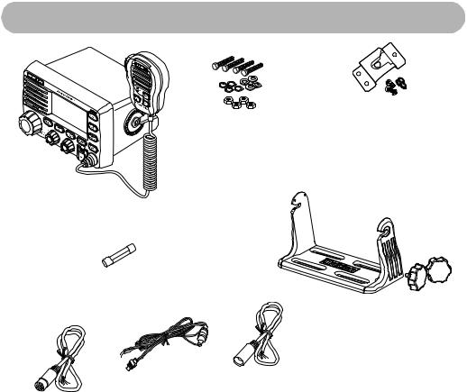
Included With the Radio
Mounting Hardware |
Microphone Mounting |
Bracket |
Radio (With Microphone Attached)
Spare Fuse
Mounting Bracket
DC Power Cord |
Hailer Cable |
|
Owner’s Manual (not shown) |
||
GPS/External Speaker Cable |
||
|
10 |
Understanding Your Radio |
Controls, Connections, and Indicators
Front Panel
Rear Panel Connectors
1HAILER connector
2WHAM connector
3GPS EXTSP (External Speaker) connector
4DC jack
52.4GHz External WHAM x 4 Antenna
6VHF Whip Antenna
1
2
3
4
5
EXT
65
Controls, Connections, and Indicators |
11 |
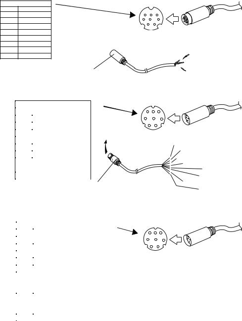
Hailer Connector/Cable
Connector Pinout |
|
|
|
||
PIN |
EXT |
|
|
|
|
1 |
Hailer 2 + |
6 |
7 |
8 |
|
2 |
Hailer 2 + |
3 |
4 |
5 |
|
|
|
|
|||
3 |
Hailer 1 + |
|
1 |
2 |
|
|
|
|
|||
4 |
Hailer 2 - |
|
|
|
|
5 |
Hailer 2 - |
|
|
|
|
6 |
Hailer 1 |
- |
|
|
|
7 |
Hailer 1 |
+ |
|
|
|
8 |
Hailer 1 |
- |
|
|
|
To Hailer Connector
To Radio
2 Green (Hailer 2 +) 
 2 White (Hailer 2 -)

 2 Brown (Hailer 1 +)
  2 Blue (Hailer 1 -)
GPS/External Speaker Connector/Cable
Connector Pinout
PIN |
EXT |
|
|
1 |
NMEA 0183 OUT - |
|
|
2 |
NMEA 0183 IN - |
|
|
3 |
NMEA 0183 OUT + |
|
|
4 |
NMEA 0183 IN + |
|
|
5 |
Not Used |
|
|
6 |
External Speaker + |
|
|
|
|
||
7 |
External Speaker -/ |
|
|
|
Ground |
|
|
8 |
Not Used |
|
|
To GPS/EXT SP Connector
8 7 6
5 4 3
2 1
To Radio
Orange (NMEA 0183 OUT -) Yellow (NMEA 0183 IN -)
Green (NMEA 0183 OUT +) White (NMEA 0183 IN +)
Red (Not Used) Brown (Ext Sp +)
Blue (Ext Sp - / Ground) Black (Not Used)
WHAM Control Unit Connector
|
Connector Pinout |
PIN |
EXT |
1 |
Ground |
2 |
DATA TX |
3 |
DATA RX |
4 |
Ground |
5 |
13.8VDC |
6 |
AUDIO TX (Signal AF |
|
received at transceiver to |
|
WHAM base station) |
7 |
AUDIO RX (Signal MIC_AF |
|
received from WHAM base |
|
station to transceiver) |
8 |
Ground |
8 7 6
5 4 3
2 1
To Radio
12 |
Controls, Connections, and Indicators |

Setting Up The Radio
Connecting the Antenna
Your UM625c has been designed to accommodate all of the popular marine VHF antennas. However, the selection and the installation of the antenna is the responsibility of the user or installer. A variety of antennas are available from a number of quality suppliers. In general, we recommend an 8' antenna rated at 6dB for powerboats, and a 4' antenna rated at 3dB for sailboats.
In general, you can increase your communication range by using a high-gain antenna placed as high as possible above the water line. Locate the antenna away from metal objects. Keep coax feed cables as short as practical.
The FCC has determined that excessive radiation poses a health risk to people near radio transmitting antennas. Therefore, the antenna used with this radio should be installed using the following guidelines to ensure a suitable distance between the antenna and persons close by.
•Small whip antennas (3 dB or smaller) should be installed keeping at least 3 feet separation distance between the radiating element and people.
•Larger antennas (6 dB or 9 dB) should be installed with at least a 6 feet separation distance.
•No person should touch the antenna or come closer than the separation distance when the radio is transmitting.
To connect the antenna to the radio, screw its connector onto the antenna jack on the back of the radio.
Connecting Power
1.Connect the red wire of the supplied power cord to the positive (+) side of your distribution circuit or battery.
2.Connect the black wire of the supplied power cord to the negative (-) side of your distribution circuit or battery.
Note: The power cord is equipped with a fuse to protect the radio. Use only a six (6) amp fast blow fuse for replacement.
3.Connect the power cord to the keyed connector on the power “pigtail”.
Installation
Caution: The UM625c is designed to use a nominal 13.8 volt negative ground battery system for power. Do not use a positive ground battery system to power the UM625c.
Keep in mind the flexibility designed into the UM625c so that you can most conveniently use it. Features which should be considered are:
•The universal mounting bracket may be installed on either the top or bottom of a shelf, on a bulkhead, or for overhead mounting.
Setting Up The Radio |
13 |
•The remote speaker wires can be used with an auxiliary speaker.
•All connections are “plug-in” type for easy removal of the radio.
•By using an optional WHAM or WHAM x 4 (Wireless Handheld Access Microphone), the UM625c can be mounted completely out of the way.
•An accessory flush mount bracket (FMB321) is optional.
Choosing a Location
Here are some important factors to consider in selecting the location for your UM625c.
•While the UM625c is completely waterproof, it will last longer if protected from spray and splash.
•Connect the UM625c directly to the battery for best operation. Always keep the battery leads as short as possible. If a direct connection can not be made with the supplied power lead, any extension should be made using #12-14 AWG wire. Use larger gauge wire for longer extensions.
•Keep the antenna lead-in wire as short as possible. If you must use a long lead-in wire as in the case of a sailboat masthead antenna installation, we recommend you upgrade your lead-in wire according to the following table:
Use RG-58 for distances less than 20 feet.
Use RG-8X for distances less than 35 feet.
Use RG-8U for distances less than 60 feet.
•Locate your antenna as high as possible and clear of metal objects. The reliable coverage range is a direct function of the antenna height.
•Select a location that allows free air flow around the heat sink on the rear of the radio.
•Select a location well away from the ship's compass. Auxiliary speakers also should be located away from the compass.
Engine Noise Suppression
Interference from the noise generated by the electrical systems of engines can sometimes be a problem with radios. The UM625c has been designed to be essentially impervious to ignition and alternator noise. However, in some installations it may be necessary to take
measures to further reduce the effect of noise interference. The UM625c radio DC battery wires, antenna lead, and accessory cables should be routed away from the engine and engine compartment, and from power cabling carrying high currents. In severe cases of noise interference, it may be necessary to install a noise suppression kit. Contact the dealer from whom you purchased the radio for more information.
Installing the Radio
After you have carefully considered the various factors affecting your choice of location, follow these steps to install the radio.
1.Position the radio (with the bracket, microphone, power cord, antenna and any auxiliary cables installed) into the selected location to assure there is no interference with the surrounding items.
14 |
Setting Up The Radio |
2.Mark the location of the mounting bracket.
3.Remove the bracket from the radio. Then use the bracket as a template to mark the holes to be drilled for the mounting hardware.
4.Drill the holes and mount the bracket with hardware compatible with the material of the mounting surface.
Note: Do not use mounting knobs other than the ones supplied. Do not insert the knobs without attaching the bracket.
5.Connect all other auxiliary cables and accessories.
Important: Do not remove the protective rubber cover from any of the connectors on the back of the radio unless you are connecting another cable to them. These rubber covers are designed to prevent water from entering the radio.
6.Install the radio in the mounting bracket and connect all cables and accessories to the appropriate jacks and connectors.
Using a WHAM or WHAM x 4 Microphone With the Radio
To connect a WHAM or WHAM x 4 microphone to the radio, follow the steps listed in “Using the WHAM and WHAM x 4 Sub Menus” on Page 41. Then, follow the steps listed in “Setting a WHAM Base ID” on Page 42, and “Changing the Radio Link Channel for a WHAM x 4” on Page 42. Otherwise, if you are connecting a WHAM x 4 microphone, follow the steps listed in “Setting a WHAM x 4 Base ID” on Page 41, “Setting the WHAM x 4 Sub Radio Mode” on Page 41, and “Changing the Radio Link Channel for a WHAM x 4” on Page 42. Then refer to the owners manual provided with the WHAM or WHAM x 4 microphone for more information about connecting it to the radio.
Important: If you want to use an external antenna for your WHAM x 4 with your UM625c marine radio, it must be installed by a professional installer. Do not attempt to connect an external antenna to a radio yourself.
Note: You cannot use a WHAM or WHAM x 4 wireless microphone to set the user MMSI, WHAM setup, system setup, or self test on the radio. You cannot use a WHAM wireless microphone to use the scrambler, intercom, GPS display, channel tag, or status message display on the radio.
Using One or Two Hailer Horns With the Radio
Connect one or two hailer horns to the radio as shown in “Hailer Connector/Cable” on Page 12. Then follow the steps listed in “Using Hail” on Page 20.
Note: The hailer horns you connect to the radio should have a rated power output of at least 35 Watts and an impedance of 2 ohms.
Setting Up The Radio |
15 |
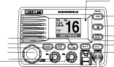
A Look at the Radio
6
2
4
1
5 3
13 Light Sensor
Used for auto dimming and color pallet changes for night operation.
12
11
10
7
9
8
1.PUSH/SELECT - Rotate to tune channels and highlight menu items you want to select, then press to select the channel you tuned or the item you selected.
2.MENU/HELP - Press to use the menu for the DSC Call, and Fog Horn. Hold down for 2 seconds to use the radio’s help function.
3.VOL - Rotate to adjust the volume.
4.MEM/UIC - Press to add to, or delete from the scan memory, the currently-tuned channel. Hold down for 2 seconds to change the channel's mode (USA/CAN/INT).
5.SQL - Rotate to adjust the squelch.
6.WX/ALERT - Press to listen to the active weather channel in your area. The radio automatically tunes to the active weather channel which it finds first. The weather channel's channel number appears on the display. Hold down for 2 seconds to set the radio to the weather alert mode (see “Using the Weather Function” on Page 23).
7.HI/LO/SCRAMBLER - Press to change the radio's output power. Hold down for 2 seconds to turn on the optional scrambler feature (see “Using the Scrambler” on Page 23).
8.DISTRESS - Lift the protective tab then hold down for 5 seconds to send a distress call (see Sending a DSC Distress Call on Page 24).
9.HAIL/INTERCOM - Press to turn on one or both hailers (see “Using Hail” on Page 20). Hold down for 2 seconds to use the radio's intercom feature (see “Using the Intercom” on Page 20).
10.STEP/SCAN - Repeatedly press to step through each channel in memory. Hold down for 2 seconds to use the radio's channel scan feature (see “Scanning Memory Channels” on
Page 22).
11.16/9 TRI - Press once to quickly tune to Coast Guard/Distress/Hailing Channel 16. Press again to quickly tune to Coast Guard/Distress/Hailing Channel 9. Press again to quickly tune to the previously-tuned channel. Hold down for 2 seconds to set the radio to the Triple Watch mode (see “Using Triple Watch” on Page 22).
12.PWR - Press to turn the radio on or off.
16 |
Setting Up The Radio |
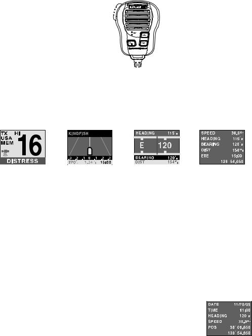
A Look at the Microphone
PTT 

PTT - Press to send a transmission. Release to hear a transmission.
 /
/ - Repeatedly press to tune channels and select menu items.
16/9 TRI - Press once to quickly tune to Coast Guard/Distress Channel 16. Press again to quickly tune to the secondary Hailing Channel 9. Press again to quickly tune to the previouslytuned channel. Press and hold to activate TRI Watch Channels 16/9 and the working channel.
A Look At the Display
(1) |
(2) |
(3) |
(4) |
You can access each of the main screens by applying power, waiting about 4 seconds, then pressing the PUSH/SELECT control once to reach the menu selector screen. Rotate the PUSH/SELECT control until you see the desired screen highlighted. Then press the control to bring up the screen. The examples shown presume that you have connected an optional GPS unit.
The RADIO screen (1) displays the selected channel and the channel name as well as other data you can select during setup. In this example, channel 16 is the Coast Guard/Distress/Hailing channel.
The XTRACK screen (2) displays direction, and bearing as well as Estimated Time Enroute if you have received a Distress, a position send from another vessel, or a position reply. The scale at the bottom is a guide to how far off course you might be. If the MMSI you receive has an associated name in your Directory, that name is automatically displayed.
The COMPASS screen (3) dynamically shows your heading and bearing. It is easily read rapidly as a convenience.
The DIGITAL screen (4) displays basic data regarding your vessel’s movement, direction, ETE, and distance.
You can display a fifth screen (5) that is similar to screen 4 starting from the RADIO screen. Press and hold the PUSH/SELECT control for approximately 2 seconds. The screen to the right appears. To return to the RADIO screen, press and release the PUSH/SELECT control.
(5)
A Look at the Display |
17 |

Basic Operation
Turning the Radio On and Off
Press PWR to turn on the radio. The radio sounds a tone and a screen showing the user MMSI appears if previously set.
If you have not set a user MMSI, see “Setting Up a User MMSI” on Page 34.
Note:If the radio is turned on for at least 3 seconds after you select a channel, it remembers the last channel you tuned when you turn it off.
Press PWR again to turn off the radio.
Selecting a Channel
Rotate PUSH/SELECT to select a channel. Rotating PUSH/SELECT clockwise tunes forward through the channels, while rotating PUSH/SELECT counterclockwise tunes backward through the channels. The currently-tuned channel appears on the display.
If the radio is set to marine mode, channel numbers appear as two digits. If the radio is set to WX mode, channel numbers appear as one digit.
Note: If A appears next to a channel number, this indicates the channel is in a simplex mode on the ship station transmit side of an international duplex channel.
Transmitting and Receiving
To transmit, hold down PTT on the microphone. TX appears on the display. Release PTT to receive. TX disappears.
Notes:
•If the channel is set to transmit at low power, you can change it to transmit at high power by pressing HI/LO/SCRAMBLER. If you are attempting to transmit on a normally power restricted channel while transmitting, press HI/LO/SCRAMBLER while holding down the PTT switch to overide the restriction. No other key except HI/LO/SCRAMBLER works.
•If you transmit continuously for longer than 5 minutes, TX and the channel number blink and the radio stops transmitting. This warns you that PTT might be stuck. To resume transmitting, release PTT then press it again.
•The radio cannot transmit on Channel 15 (USA).
•If you hold down PTT while turning on the radio, the radio sounds an error tone and TX and the channel number blink. No key except HI/LO/SCRAMBLER works.
•You cannot transmit while the radio is set to WX mode or Scan mode. If you press PTT while the radio is set to Scan mode, the radio cancels that mode but does not transmit.
•The radio cannot transmit voice data on Channel 70. Only DSC data such as a Distress Call can be transmitted on Channel 70.
18 |
Basic Operation |
 Loading...