

Page 1

CONTENTS
Introduction . . . . . . . . . . . . . . . . . . . . . . . . . . . . . . . . . . . 3
Important Notice . . . . . . . . . . . . . . . . . . . . . . . . . . . . . . . 4
Terminology . . . . . . . . . . . . . . . . . . . . . . . . . . . . . . . . . . 5
What is Scanning?. . . . . . . . . . . . . . . . . . . . . . . . . . . 5
What is Searching? . . . . . . . . . . . . . . . . . . . . . . . . . . 5
What is Trunk Tracking? . . . . . . . . . . . . . . . . . . . . . . 5
Feature Highlights. . . . . . . . . . . . . . . . . . . . . . . . . . . . . . 7
Where to Obtain More Information . . . . . . . . . . . . . . . . . 8
Information on the Internet. . . . . . . . . . . . . . . . . . . . . 8
Included with Your Scanner . . . . . . . . . . . . . . . . . . . . . . 9
Setup. . . . . . . . . . . . . . . . . . . . . . . . . . . . . . . . . . . . . . . 10
Installing the Batteries . . . . . . . . . . . . . . . . . . . . . . . 10
Charging the Battery Pack. . . . . . . . . . . . . . . . . . . . 11
CRX120 Battery Charger. . . . . . . . . . . . . . . . . . . . . 12
Adapter Safety Feature . . . . . . . . . . . . . . . . . . . . . . 13
Flexible Antenna . . . . . . . . . . . . . . . . . . . . . . . . . . . 14
Belt Clip . . . . . . . . . . . . . . . . . . . . . . . . . . . . . . . . . . 14
Basic Operation. . . . . . . . . . . . . . . . . . . . . . . . . . . . . . . 15
Setting the Squelch . . . . . . . . . . . . . . . . . . . . . . . . . 15
Keylock . . . . . . . . . . . . . . . . . . . . . . . . . . . . . . . . . . 16
Programming. . . . . . . . . . . . . . . . . . . . . . . . . . . . . . . . . 17
Duplicate Frequency Alert . . . . . . . . . . . . . . . . . . . . 19
Programming Tips . . . . . . . . . . . . . . . . . . . . . . . . . . 19
Deleting a Stored Frequency . . . . . . . . . . . . . . . . . . 20
Scanning . . . . . . . . . . . . . . . . . . . . . . . . . . . . . . . . . . . . 21
Channel Lockout . . . . . . . . . . . . . . . . . . . . . . . . . . . 22
Lockout in Manual Mode . . . . . . . . . . . . . . . . . . . . . 22
Lockout in Scanning Mode. . . . . . . . . . . . . . . . . . . . 23
Lockout Tips. . . . . . . . . . . . . . . . . . . . . . . . . . . . . . . 23
Restore a Locked Out Channel . . . . . . . . . . . . . . . . 24
Restore All Locked-Out Channels . . . . . . . . . . . . . . 24
Priority Scan. . . . . . . . . . . . . . . . . . . . . . . . . . . . . . . 25
Changing the Priority Channel. . . . . . . . . . . . . . . . . 26
Searching . . . . . . . . . . . . . . . . . . . . . . . . . . . . . . . . . . . 27
Setting a Search Range. . . . . . . . . . . . . . . . . . . . . . 27
Search Hold Feature . . . . . . . . . . . . . . . . . . . . . . . . 28
Data Skip . . . . . . . . . . . . . . . . . . . . . . . . . . . . . . . . . 28
Channel Skip . . . . . . . . . . . . . . . . . . . . . . . . . . . . . . 29
Storing Search Frequencies. . . . . . . . . . . . . . . . . . . 29
SVC Scanning. . . . . . . . . . . . . . . . . . . . . . . . . . . . . . . . 31
SVC Scan Lockout. . . . . . . . . . . . . . . . . . . . . . . . . . 33
Programming with SVC Scan . . . . . . . . . . . . . . . . . 33
Trunk Tracking . . . . . . . . . . . . . . . . . . . . . . . . . . . . . . . 35
Types of Trunking Systems . . . . . . . . . . . . . . . . . . . 35
Setting the Squelch . . . . . . . . . . . . . . . . . . . . . . . . . 37
Programming Trunking Frequencies . . . . . . . . . . . . 37
Page 2

Searching a TrunkedBank.. ... ... ... ... ... ..39
IDHold Mode. ... ... ... ... ... ... ... ... ... ..41
IDLockout... ... ... ... ... ... ... ... ... ... ..42
Restore a SingleID.. ... ... ... ... ... ... ... ..42
Restore all IDs... ... ... ... ... ... ... ... ... ..43
Searching Tips... ... ... ... ... ... ... ... ... ..43
Channel Activity Indicators... ... ... ... ... ... ..44
Scan Lists... ... ... ... ... ... ... ... ... ... ..46
Deletinga Stored ID.. ... ... ... ... ... ... ... ..49
Fleet MapProgramming. ... ... ... ... ... ... ... ..50
Selecting Trunking Programming Mode.. ... ... ..50
Selecting a Preset Fleet Map. ... ... ... ... ... ..51
Programming a FleetMap... ... ... ... ... ... ..52
Programming a Hybrid System.. ... ... ... ... ..53
Care andMaintenance.. ... ... ... ... ... ... ... ..54
GeneralUse.. ... ... ... ... ... ... ... ... ... ..54
Location.. ... ... ... ... ... ... ... ... ... ... ..54
Cleaning.. ... ... ... ... ... ... ... ... ... ... ..54
Repairs... ... ... ... ... ... ... ... ... ... ... ..55
Birdies... ... ... ... ... ... ... ... ... ... ... ..55
Troubleshooting. ... ... ... ... ... ... ... ... ... ..56
Specifications... ... ... ... ... ... ... ... ... ... ..58
Appendix. ... ... ... ... ... ... ... ... ... ... ... ..59
Preset Fleet Maps... ... ... ... ... ... ... ... ..59
User Defined FleetMaps. ... ... ... ... ... ... ..61
OneYear LimitedWarranty.. ... ... ... ... ... ... ..64
2
Page 3

Introduction
The
BC 235XLT
TrunkTracking™
can store frequencies such as police, fire/emergency,
marine, air, amateur, and other communications into 10
banks of 30 channels each.
Use your new scanner to monitor:
800 MHz Trunked Public Safety Systems
Police and Fire Departments (including rescue and
paramedics)
NOAA Weather Broadcasts
Business/Industrial Radio
Utilities
Marine and amateur (ham radio) bands
Air band
Frequency Range Steps Transmission
29.0-29.7 MHz 5 kHz 10 Meter Amateur Band
29.7-50.0 MHz 5 kHz VHF Low Band
50.0-54.0 MHz 5 kHz 6 Meter Amateur Band
108-137 MHz 12.5 kHz Aircraft Band
137-144 MHz 5 kHz Military Land Mobile
144-148 MHz 5 kHz 2 Meter Amateur Band
148-174 MHz 5 kHz VHF HighBand
406-420 MHz 12.5 kHz Federal Govt.
420-450 MHz 12.5 kHz 70cm Amateur Band
450-470 MHz 12.5 kHz UHF Standard Band
470-512 MHz 12.5 kHz UHF “T” Band
806-956 MHz 12.5 kHz Public Service “800”
is a brand new state-of-the-art radio with
and automatic scanning capabilities. It
Band
3
Page 4

Important Notice
This scanning radio has been manufactured so
that it will not tune to the radio frequencies
assigned by the FCC for cellular telephone usage.
The Electronic Communications Privacy Act of
1986, as amended, makes it a federal crime to
intentionally intercept cellular or cordless
telephone transmissions or to market this radio
when altered to receive them.
The installation, possession, or use of this
scanning radio in a motor vehicle may be
prohibited, regulated, or require a permit in certain
states, cities, and/or local jurisdictions. Your local
law enforcement officials should be able to provide
you with information regarding the laws in your
community.
Changes or modifications to this product not
expressly approved by Uniden, or operation of this
product in any way other than as detailed by this
Operating Guide, could void your authority to
operate this product.
The screen displays used in this manual are
representations of what might appear when you
use your scanner.
4
Page 5

Terminology
What is Scanning?
Unlike standard AM or FM radio stations, most two-way
communications do not transmit continuously. The
BC 235XLT
active frequency.
Scanning stops on an active frequency and remains on
that channel as long as the transmission continues. When
the transmission ends, the scanning cycle resumes until
another transmission is received.
What is Searching?
The
BC 235XLT
active frequencies. This is different from scanning because
you are searching for frequencies that have not been
programmed into your scanner. You can choose between
two speeds while searching.
for Uniden scanners, can search the
300 channels per second.
What is Trunk Tracking?
scans programmed channels until it finds an
can search each of its 12 bands to find
Turbo Search
, a new feature
VHF FM
bands at up to
Conventional scanning is a simple concept. You enter a
radio frequency in your scanner’s memory which is used
by someone you want to monitor. For example, the police
in your area may broadcast on 460.500 MHz , the fire
department on 154.445 MHz, the highway department on
37.900 MHz, etc. So when your scanner stops on a
frequency, you usually know who it is, and more
importantly, you can stop on a channel and listen to an
entire conversation. This type of scanning is easy and fun.
As the demand for public communications has increased,
many public radio users don’t have enough frequencies to
meet their needs, and this has created a serious problem.
Trunking radio systems solve this problem.
5
Page 6

In a trunked radio system, which contains up to 29 different
frequencies, radio users are divided into groups, often
called talk groups, and these talk groups are assigned
specific IDs. When someone in a talk group uses their
radio, a brief bust of data is broadcast before each
transmission. The trunking system computer uses this data
to temporarily assign each radio in a talk group to an
available frequency. If the group using a frequency stops
broadcasting or pauses between replies for a few seconds,
they are removed from the frequency so another talk group
can use it.
Sharing of the available public service frequencies, or
trunking, allows cities, counties, or other agencies to
accommodate hundreds of users with relatively few
frequencies. On the other hand, following a conversation
on a trunked system is difficult, if not impossible, because
when there’s a short break during the conversation you’re
monitoring, it’s possible that the talk group will be assigned
to a completely different frequency in the trunked system.
This type of scanning is difficult and frustrating.
TrunkTracker™
BC 235XLT
changes this! Not only does your new
scan channels like a conventional scanner, it
actually follows the users of a trunked radio system. Once
you know a talk group’s ID, you won’t miss any of the
action.
If you’re a new scanner enthusiast, you may want to read
the first part of this manual and use your scanner in
conventional mode before you begin trunk tracking.
Understanding scanning fundamentals and its terminology
will make trunk tracking much easier. But if you’re already
a sophisticated scanner operator, you may want to go to
Trunk Tracking
on page 35 now.
6
Page 7

Feature Highlights
Trunk Tracking – Follow 800 MHz trunked public
safety and public service systems just as if
conventional two-way communications were used.
300 Channels – Program one frequency into each
channel. You must have at least one channel
programmed to use the Scan mode.
12 Bands, 10 Banks – Includes 12 bands, with
Aircraft and 800 MHz. 10 banks with 30 channels
each are useful for storing similar frequencies to
maintain faster scanning cycles or storing all the
frequencies of a trunked system.
29 MHz-956 MHz – Indicates the range of
frequencies that can be searched within the bands
of your scanner.
Note: The frequency coverage is not continuous
and excludes the cellular band.
10 Priority Channels – You can assign one
priority channel in each bank. Assigning a priority
channel allows you to keep track of activity on your
most important channel(s) while monitoring other
channels for transmissions.
Preprogrammed Service (SVC) Search – Allows
you to toggle through preprogrammed police,
fire/emergency, aircraft, marine, and weather
frequencies.
Unique Data Skip – Allows your scanner to skip
unwanted data transmissions and reduces birdies.
Memory Backup – If the battery completely
discharges or if power is disconnected, the
frequencies programmed in your scanner are
retained in memory.
Manual Channel Access – Go directly to any
channel.
LCD Back Light – An LCD light remains on for 15
seconds when
Battery Save – In manual mode, your scanner
automatically reduces its power requirements to
extend the battery’s charge.
is pressed.
K
7
Page 8

Where to Obtain More
Information
Before using your scanner, you must program frequencies
into available channels. The
lists typical frequencies used around the U.S.A. and
Guide
Canada that you may program into your new scanner.
To order a copy of the frequency guide, call the enclosed
Mr. Scanner (800) Number. A Uniden representative
should be able to order you a copy of Betty Bearcat for
your area and provide you with sample frequencies. You
can also use the enclosed order form to purchase a local
frequency list.
The Bearcat Radio Club, and other similar hobby clubs,
have publications, information on computer bulletin boards,
and even contests for the radio enthusiast. Also, your local
library has more information.
Information on the Internet
If you have access to the Internet, you may want to visit
www.trunktracker.com
may contain manufacturer information, frequency data, and
ID information as it becomes available.
Betty Bearcat Frequency
, which is under development, and
For more information about Uniden and our other products,
www.uniden.com
visit
.
8
Page 9
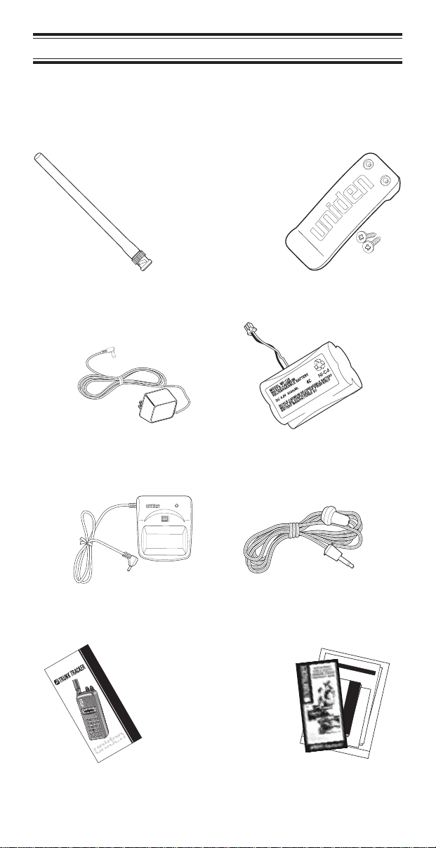
Included with Your Scanner
If any of these items are missing or damaged, immediately
contact your place of purchase or Uniden Customer
Service at: (800) 297-1023, 8:00 a.m. to 5:00 p.m., Central,
Monday through Friday.
Antenna Belt Clip
AC Adapter
(AD70U)
AC Adapter 2 Battery Packs
CHARGE
RED
BLK
Charging Cradle Earphone
300-Channel Trunk Tracking Scanner
BC 235X LT
TM
Operating Guide
UDZZ01818ZZ
Operating Guide
9
Programmable100-Channel BaseScanner
BC XLT860
Now is the time for all good men to
come to the aid of the party.
Four score yeas ago our fathers set
forth a new nation conceived in
Liberty and dedicated to the
proposition that all men are
created equal. The quick brown
fox jumped over the garden wall.
Now is the time fo4r all good men to
come to the aid of the party.
Programmable100-ChannelBase Scanner
BC XLT860
Now is the time for all good men to
come to the aid of the party.
Four score yeas ago our fathers set
forth a new nation conceived in
Programmable100-ChannelBase Scanner
BC XLT860
Liberty and dedicated to the
proposition that all men are
Now is the time for all
created equal. The quick brown
good men to come to the
fox jumped over the garden wall.
aid of the party. Four
Now is the time fo4r all good men to
score yeas ago our
come to the aid of the party.
fathers set forth anew
100
CH
A
N
N
E
nation conceived in
LBAND
M
H
zSCAN
N
IN
G
R
ADIOBCXLT12800 860
Now is the time for all good men to
Liberty and dedicated to
TWINTURBO
DATABA
come to the aid of the party.
N
K
12345678910
the proposition that all
P
100
SC
A
888.8888
N
W
X
PR
A
I
OR
I
R
I
T
Y
SR
C
H
H
Four score yeas ago our fathers set
O
L
D
D
E
men are created equal.
L
A
YL
1
S
Q
1-10
/
O
U
E
L
CH
2
11-2
0
3
2
TURB
1
-3
4
0
O
3
1
/
-4
forth a new nation conceived in
P
0
R
IORIT
5
The quick brown fox
Y
4
1
-5
0
D
A
6
AUTO
TA
5
1
-6
7
WE
0
6
A
1
T
-7
H
0
E
LIM
R
IT
8
7
1
-8
S
E
0
A
Liberty and dedicated to the
R
CH
9
8
1
jumped over the garden
-9
HOLD
0
.
VOLUM
DE
0
L
E
AY
9
1
-10
0
E
LOCKOUT
proposition that all men are
S
C
A
N
wall. Now is the time fo4r
M
OFF
A
N
U
A
L
created equal. The quick brown
all good men to come to
fox jumped over the garden wall.
the aid of the party.
Now is the time fo4r all good men to
come to the aid of the party.
Now is the time for all
good men to come to the
Now is the time for all good men to
aid of the party. Four
come to the aid of the party.
score yeas ago our
Four score yeas ago our fathers set
fathers set forth anew
forth a new nation conceived in
nation conceived in
Liberty and dedicated to the
Liberty and dedicated to
the proposition that all
men are created equal.
The quick brown fox
jumped over the garden
wall. Now is the time fo4r
all good men to come to
Frequency Guide
and Other Printed
Material
Page 10
Setup
These are helpful guidelines when using your new scanner:
If your scanner receives interference or electrical
noise, move the scanner or its antenna away from
the source.
If you need to improve reception, use an optional
antenna designed for multi-band coverage. (You
can purchase this type of antenna at a local
electronics store.)
Use the included earphone or an optional stereo
headset with proper impedance for private
listening. Read the precautions on the inside front
cover of this Guide.
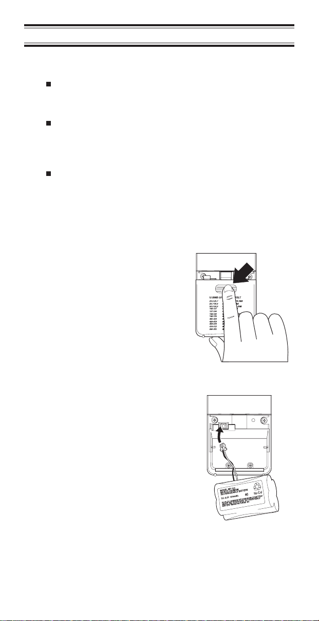
Installing the Batteries
1. Open the cover.
2. Insert the battery
pack.
10
Page 11
3. Replace cover and
press down until it
clicks into place.
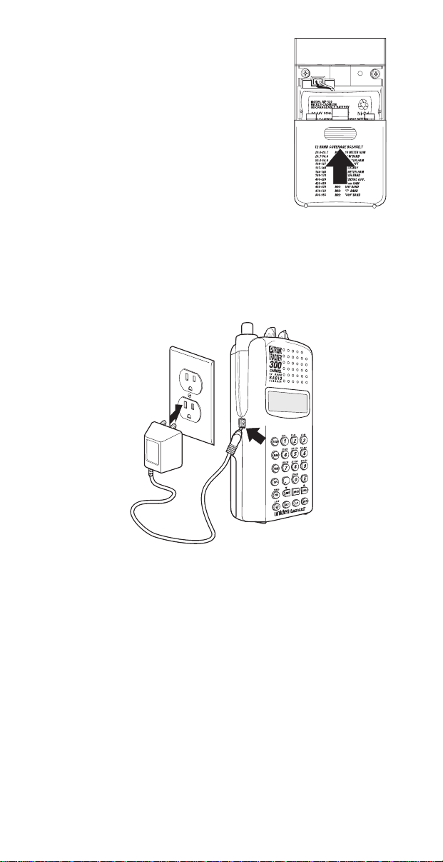
Charging the Battery Pack
Use the AC Adapter/Charger to power the
from an AC outlet.
Use only the supplied AC Adapter
(AD70U)
You can use your scanner while the battery charges. To
fully charge the battery, leave the AC Adapter/Charger
connected for 14 – 16 hours.
or one of the optional power
cords
(WZ1015 or WZ1017)
BC 235XLT
.
Note: Disconnect the AC Adapter/Charger from the unit
when charging is complete.
11
Page 12
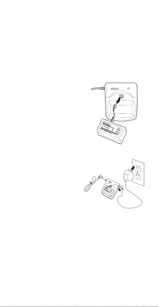
CRX120 Battery Charger
The CRX120 charger allows you to charge the extra
battery included with your scanner. You can also charge
the battery inside your scanner at the same time. This way
you can always have a charged battery ready to go.
Charging the Spare Battery
To fully charge the extra battery in the CRX120, you
should leave the battery in the charger for 14 – 16 hours.
1. Plug the cable from
the BP180 into the
connector in the
CRX120. Make sure
the red wire matches
RED
and the black
wire matches
BLK
the charger.
2. Place the battery in
the charger, and plug
the AC Adapter into a
wall outlet.
Then connect the
adapter to the
charger.
The red LED on the
charger will light,
indicating that the
battery is charging.
on
CHARGE
RED
BLK
DCIN12V
12
Page 13

Connecting the Charger to Your Scanner
You can charge both batteries at the same time. To fully
charge both batteries, you should leave the AC
Adapter/Charger connected for 14 – 16 hours.
1. Follow steps 1 and 2
Charging the
under
Spare Battery
page 12, then
connect the charging
lead on the CRX120
to the charging jack
on your scanner.
2. When charging is
complete, disconnect
the CRX120 from
your scanner, then
unplug the AC
Adapter/Charger from
the CRX120.
on
DCIN12V
Adapter Safety Feature
The AC Adapter included with this scanner may be
equipped with a polarized line plug — a plug with one
blade wider than the other. This plug will fit into a power
outlet only one way. If you are unable to insert the
adapter’s plug into an outlet, try reversing the plug.
13
Page 14
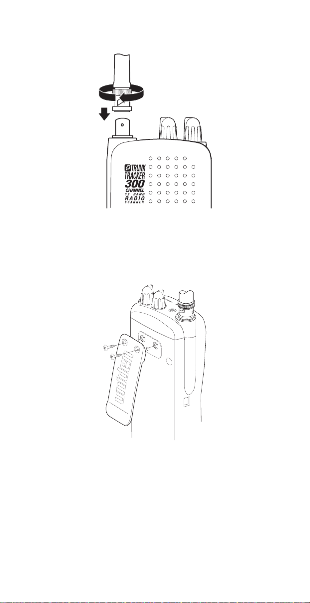
Flexible Antenna
Attach the flexible antenna to the
Belt Clip
BNC
connector.
Do not tighten the screws too tight.
You can damage the case or clip.
14
Page 15
Basic Operation
Note: You can fold out the Front Cover to see the
Controls and Indicators while reading this Guide.
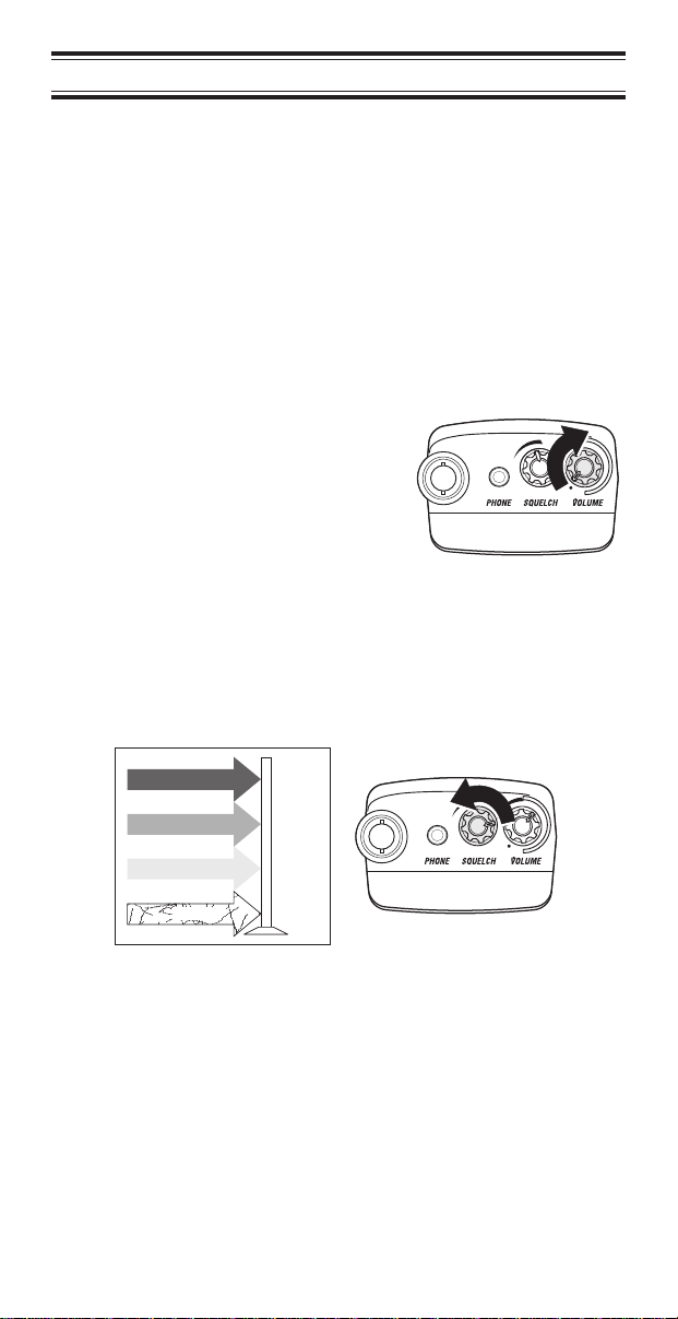
Setting the Squelch
To set the squelch, you must be in the Manual mode, and
you should not be receiving a signal on your scanner.
1. Press
until you do
M
not hear a signal.
2. Adjust
VOLUME
to a
comfortable listening
level.
3. Think of the Squelch Control as a gate. Turn
SQUELCH
fully counter-clockwise. This raises the
“Squelch Gate” so high that only very strong signals
can get through.
STRONG SIGNALS
MEDIUM SIGNALS
WEAK SIGNALS
NOISE
15
Page 16
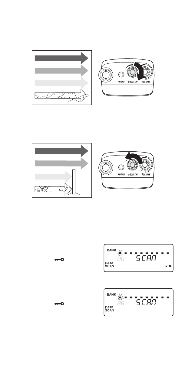
4. Turn
SQUELCH
fully clockwise until you hear a hiss.
This lowers the “Squelch Gate” so that everything
gets through—noise, weak signals, and strong
signals.
STRONG SIGNALS
MEDIUM SIGNALS
WEAK SIGNALS
NOISE
5. Turn
SQUELCH
back counter-clockwise just until the
hiss stops. Now the “Squelch Gate” allows only
clearer signals through.
STRONG SIGNALS
MEDIUM SIGNALS
WEAK SIGNALS
NOISE
Keylock
Key Lock prevents accidental key entries during
conventional scanning or while in trunk tracking mode.
1. To lock the keypad,
press and hold
LOCK
until the symbol
appears in the lower
right of the display.
2. To unlock the keypad,
press and hold
LOCK
until the symbol
in the lower right of
the display turns off.
12345678910
12345678910
16
Page 17
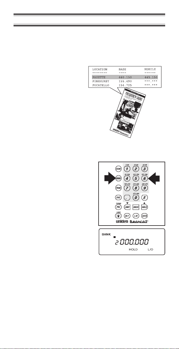
Programming
Before the
you must program a frequency into at least one channel.
Repeat this procedure for each channel you want to
program.
1. Select frequencies
2. Press
3. Select a channel.
BC 235XLT
from your starter
guide.
.
M
a. Enter the channel
number.
b. Then press
can begin conventional scanning,
a
M
.
b
17
12345678910
Page 18
4. Enter the frequency.
a. Enter the frequency
number.
b. Then press
E
.
a
b
12345678910
Note: To clear a mistake while entering the frequency,
press
twice, and start over.
.
If you enter a
frequency which is
outside the scanner’s
frequency bands, a
distinctive beep
sounds.
Press
back to Step 4.
(See the Table on page 3 or the Band List on the
back of the scanner).
.
and go
12345678910
18
Page 19

Duplicate Frequency Alert
If you enter a
frequency which is
stored in another
channel, you hear a
beep and the other
channel displays.
Press
again
—OR—
PressEagain to
store the frequency in
both channels.
.
to start
Programming Tips
Do not program a weather frequency into one of
the channels, since weather channels transmit
continuously.
Use
Group similar frequencies into adjacent channels.
For example, program police frequencies in
channels 1 through 10 and fire/emergency into
channels 11 through 20, and so on.
Put the frequency that you listen to the most or the
most important frequency into a Priority channel.
To quickly program a series of channels, start with
the lowest number channel.
For example, when you are programming five new
frequencies into Channels 4 through 8, start with
Channel 4. After you finish programming a
channel, press
channel.
Record channels and frequencies in some
convenient place in case the scanner memory is
lost.
to select the weather information band.
C
12345678910
or)to go to the next higher
M
19
Page 20

Deleting a Stored Frequency
To delete a stored
frequency:
a. Press
b. Then press
Channels with no
frequencies are
automatically locked
out.
0
.
E
12345678910
.
20
Page 21
Scanning
1. After programming
frequencies, simply
press
scanning.
2. The indicator for each bank which will be scanned
appears in the display, while the bank being
currently monitored flashes. You can deselect banks
from active scanning by pressing their number on
your keypad. The indicator for each deselected bank
turns off, and the bank’s channels are not scanned.
Note: One Bank must always be active. You cannot
deactivate all ten banks at the same time. If you try
to turn all the banks off, the first bank is
automatically selected.
To restore a bank to active scanning, press the
bank’s number on your keypad. The bank’s indicator
will display again.
3. During normal
scanning the scanner
skips unprogrammed
or locked out
channels.
S
to begin
CHANNELS
1 3 4 5 9 102 6 7 8
SCAN
4. When a transmission
is received, the
Scanner stops on that
channel. When the
transmission ends,
scanning resumes
automatically.
21
Frequency
Locked Out
12345678910
(L/O)
Frequency not
entered
Page 22

5. PressMto stop on a
channel during
scanning.
12345678910
6. Press
scanning.
to resume
S
Channel Lockout
You can lockout any channel so it is not reviewed during
normal scanning. You can restore the channel to scanning
whenever you wish.
Lockout in Manual Mode
1. PressM.
2. Select a channel.
a. Enter the channel
number.
b. Then press
again.
b
M
a
3. Press
the channel.
to lockout
O
12345678910
12345678910
22
Page 23

Lockout in Scanning Mode
If the scanner keeps stopping on a particular channel due
to noise or too frequent transmissions, you may want to
keep that channel from scanning.
1. Wait until the scanner
stops at the channel.
2. Then press
3. The scanner
immediately resumes
scanning because the
locked out channel is
no longer in the
scanning sequence.
O
.
Lockout Tips
To quickly lockout a series of channels, start with
the lowest number channel.
For example, if you are locking out channels 4, 7,
8, 12, and 15, start with Channel 4. After selecting
channel 4, press
times to step up to the next channel to be locked
out.
Record the locked-out channels in some
convenient place so you can restore them.
12345678910
. Then pressMone or more
O
23
Page 24

Restore a Locked Out Channel
1. PressM.
2. Select a locked out
channel.
a. Enter the channel
number.
b. Then press
again.
M
b
a
12345678910
3. Press
the channel.
O
to unlock
12345678910
Restore All Locked-Out Channels
You can restore all locked-out channels in a bank only
when a bank is selected for scan. If you have deselected a
bank and you want to restore all of its locked-out channels
using the steps below, you must press
the number of the bank on your keypad.
1. Press
Note: You must be in
Manual mode before
restoring all
locked-out channels.
M
.
and then press
S
24
Page 25

2. Press and hold
for about two seconds.
O
You will hear two
beeps when all the
channels have been
restored.
Priority Scan
When Priority Scan is turned on, your scanner checks the
priority channel every two seconds for activity. If a signal is
present on the priority channel, your scanner monitors the
channel until the transmission ends, then resumes normal
scanning. You can designate one channel in each bank as
a Priority Channel.
To activate Priority Scan (in either the Manual or Scan
Mode):
1. Press
P
.
Note: If you have
locked out the priority
channel, this
message appears
when you select
Priority mode.
2. PressPagain at
anytime to deactivate
Priority Scan.
12345678910
12345678910
25
Page 26

Changing the Priority Channel
You cannot eliminate the Priority Channel, but you can
change it to any of the 30 available channels in each bank.
1. Press
2. Select a new Priority
Channel.
3. Press and hold
for two seconds to
designate this
channel as your new
Priority Channel.
.
M
a. Enter the channel
number.
b. Then press
again.
M
P
b
12345678910
a
Two beeps indicate
that the Priority
Channel is changed.
12345678910
26
Page 27

Searching
Setting a Search Range
The
BC 235XLT
find frequencies if you don’t have a frequency guide
available or if new stations have been added since your
guide was published.
can search a specific frequency range to
1. Press
scanning.
2. Using your keypad,
enter the lowest
frequency of your
search range. For
example, enter
155.000 MHz.
3. Press
4. Using your keypad,
enter the highest
frequency of your
search range. For
example, enter
157.000 MHz.
5. Press
6. Press
Note: When Search mode is active, press
TURBO
300 steps per second in those bands which have
5 KHz steps.
active. PressPagain to cancel
to stop
M
12345678910
.
L
12345678910
.
L
.
R
search to increase the search speed to
SRCH
flashes when
TURBO
TURBO
to activate
P
search is
search.
27
Page 28

Search Hold Feature
1. PressHat anytime
to stop the search.
2. Press
to move to
)
the next higher
12345678910
12345678910
frequency
—OR—
3. Press(to move
down to the previous
12345678910
frequency.
4. Press
to resume
R
searching.
Data Skip
A scanner will normally stop on any transmission it
receives. This means the
BC 235XLT
signals and unmodulated transmissions. You can
automatically skip many of these types of transmissions
during searches.
will stop on data
1. Press
the data skip feature.
The
D
d
to activate
indicator
12345678910
appears on the
display.
2. PressDagain to
cancel the data skip
12345678910
feature.
The
d
indicator
disappears from the
display.
When data skip is active, your scanner may pause
momentarily on an unwanted signal but will resume
searching in 2 or 3 seconds. Data Skip does not function
AIR
when the
Band is selected.
28
Page 29

Channel Skip
If a particular channel continues to interrupt search
scanning, it is possible to set your scanner to skip the
frequency.
To skip a frequency,
press
O
.
Note: You can
program up to 20 skip
frequencies. The 21st
skip frequency
entered causes the
first skipped
frequency to unlock.
Storing Search Frequencies
You can quickly store any frequency you find during
Search.
Caution: You must select the channel in which you will
store the frequency before entering the search
mode. Otherwise, you may erase a stored
frequency that you want to keep.
1. PressM.
2. Using your keypad,
enter the lowest
frequency of your
search range. For
example, enter
155.000 MHz.
3. Press
4. Using your keypad,
enter the highest
frequency of your
search range. For
example, enter
157.000 MHz.
L
.
12345678910
12345678910
29
Page 30

5. PressL.
6. Press
7. Press
scanner stops at the
frequency you want.
8. Press
frequency in the
channel you selected.
.
R
when the
H
to store the
E
Note: After this step
you are in manual
mode.
9. To store another
frequency, select
another channel for
the new frequency.
10. Repeat steps 6
through 8 for all the
Search frequencies
you want to store.
12345678910
12345678910
30
Page 31

SVC Scanning
The ServiceCScan feature allows you to toggle through
five bands preprogrammed for police, fire/emergency,
aircraft, marine, and weather. The frequencies selected for
these bands are the most commonly used around the U.S.
1. Press
POLICE
.
C
appears
beneath the blinking
channel number, and
a frequency displays.
2. After a two second
delay, scanning
begins.
PressSto start
scanning immediately
or to continue
scanning if you want
to skip a frequency.
3. PressCto scan the
FIRE/EMG
4. Press
AIR
C
bank.
bank.
to scan the
12345678910
12345678910
12345678910
12345678910
5. Press
MRN
C
bank.
to scan the
12345678910
31
Page 32

When an active
channel is displayed,
the scanner will
alternate between the
frequency and the
Marine channel
number. For example,
156.800 alternates
with CH 16.
12345678910
AND
12345678910
6. PressCto scan the
WX
band.
12345678910
Note: It’s possible to
receive more than
one weather
broadcast in your
area. If the broadcast
sounds weak or
distant, press
S
again to look for a
closer station.
7. To exit SVC Scan
mode, press
During search of one of the preprogrammed service bands,
press
in the display. Press
programmed frequency, or press
to stop the scan on a frequency.
H
.
M
(or)
HOLD
appears
to move up or down one
to resume scanning.
S
Note: If you want to remain on a channel until a
responding transmission is received, press
Y
to
activate the two second delay feature.
32
Page 33

SVC Scan Lockout
Follow these steps to lockout frequencies during Service
scanning:
You cannot lockout weather frequencies.
Note:
1. PressHto stop the
Service Scan.
2. Press
3. Press
.
O
to resume
S
scanning.
12345678910
12345678910
12345678910
Note: You can lockout up to 20 frequencies in SVC Scan
mode. The 21st locked out frequency entered
causes the first locked out frequency to unlock.
Programming with SVC Scan
Follow these steps to program frequencies into a channel
during Service scanning:
1. Select a channel you
want to program.
12345678910
Note: If a frequency
is already stored in
the channel you
select it will be erased
when you save the
new frequency.
33
Page 34

2. PressCto select
Service Scan mode.
Repeat until you
select the service
mode you want.
3. Press
scanning.
4. When SVC Scan
stops on a frequency
you want, press
5. Press
frequency in the
channel you selected.
to begin
S
to store the
E
H
12345678910
.
12345678910
34
Page 35

Trunk Tracking
Your
BC 235XLT
Type II, Type IIi, Hybrid,
analog trunking systems
800 MHz communication systems. When tracking these
types of systems, you may want to remember these
important points:
Your scanner defaults to monitor Type II systems;
however, you can change this if the system in your
area is different. (The types of systems are
discussed below.)
Your scanner cannot track an 800 MHz trunked
system and scan frequencies in conventional
mode at the same time.
The frequencies for many of the 800 MHz public
safety systems are listed in the
National Public Safety Trunked System Frequency
Guide
If you have internet access, you can visit
www.trunktracker.com
information about Trunk Tracking Scanning.
*
Motorola,
trademarks of Motorola Inc.
is designed to track Motorola Type I,
SMARTNET™, and PRIVACY PLUS™
, which are extensively used in
*
TrunkTracker™:
included with your
SMARTNET
BC 235XLT
for current news and
, and
PRIVACY PLUS
scanner.
are
Types of Trunking Systems
Trunking systems divide a few frequencies among many
different users, but the way that each system does this is
slightly different. There are really two basic types which are
important when using your TrunkTracker™ scanner. These
are usually referred to as Type I and Type II systems.
One important distinction between these two systems is
the amount of data transmitted by each radio when its
push-to-talk button (PTT) is pressed. Every radio in a
trunked system is assigned a unique ID so the central site
computer can identify it when it’s used. Both Type I and
Type II systems place radios (or radio users) into groups,
called talk groups, and these talk groups are also assigned
unique IDs. Some radios have access to only one talk
group, while others have access to many talk groups.
Which talk group(s) each radio can access is called the
radio’s affiliation(s).
35
Page 36

In a Type II system, when someone uses their radio, only
the radio ID is transmitted when PTT is pressed, whereas
in a Type I system the radio ID and its current affiliation are
both transmitted when PTT is pressed.
Why the difference? Type II systems are slightly more
advanced because the central computer maintains a
database which is used to determine each radio’s
affiliation(s). Changes to a Type II system are easier than
Type I because the system manager only need update the
database instead of reprogramming individual radios.
Another difference between the systems is that Type I
systems are arranged in a Fleet-Subfleet hierarchy. For
example, it’s possible for a city using a Type I system to
designate 4 Fleets, each with 8 Subfleets. Their fleets
might be the Police Department, the Fire Department,
Utilities, and Administration. The Police may decide to
further divide their fleet into subfleets such as Dispatch,
Tactical Operations, Detectives, North, South, East and
West Side Patrols, and Supervisors. All the available police
radios would then be assigned to one of the police
subfleets. Determining the exact Fleet-Subfleet hierarchy
for a particular area is referred to as Fleet Map
Programming.
The disadvantage of a Type I system is that when PTT is
pressed, the brief bust of data must contain the radio’s ID
and its Fleet and Subfleet. This is three times the amount
of data a Type II system radio sends, and as a result
Type I systems usually accommodate fewer users than
Type II systems.
Even though there are many Type II systems, Type I
systems are still in use. There are also Hybrid systems
which are a combination of both Type I and Type II. Your
scanner defaults to monitor Type II systems, but it’s
possible to select a Preprogrammed Fleet Map or create a
Custom Fleet Map for your area.
36
Page 37

Setting the Squelch
Since Squelch is automatically adjusted in trunking mode,
it isn’t necessary to manually adjust the squelch control
while trunk tracking. However, the squelch setting you
select before you begin trunk tracking can affect how fast
your scanner acquires the data channel, and, in some
instances, the squelch setting can prevent your scanner
from acquiring the data channel at all.
Set
SQUELCH
position before
selecting a trunking
bank.
Note: You can
change this
recommended
setting, if necessary,
to provide better
performance in your
area.
in this
Programming Trunking Frequencies
Before you start programming your scanner to track a
trunked system, consider the following:
You can only program one trunking system in each
bank of your scanner.
Trunking frequencies must be entered while in the
Trunking Programming mode.
If you’re in the Trunking Programming mode, you
cannot select channels in other banks.
For example, if you are programming Bank 4, you
can only select channels 91-120 with the
keys.
37
(or)
Page 38

The first step in tracking a trunked system is storing the
frequencies in one of the 10 available banks in your
scanner.
1. Press and hold
T
.
You will hear two
BANK
beeps, and
TRUNK
will begin to
and
flash in the display.
2. Choose the bank you
want to trunk track.
For example, press
.
2
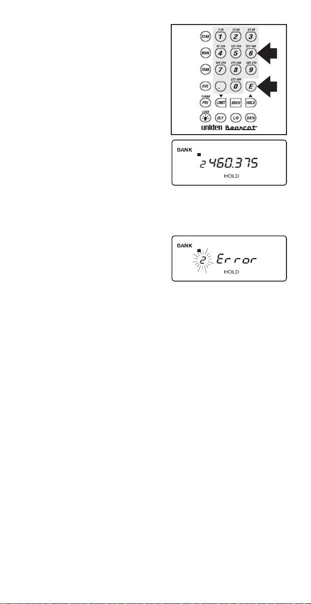
3. Use the keypad to
enter a frequency for
the trunked system.
For example, enter
856.2625, or enter a
frequency of the
system you’re going
to track.
Then press
E
.
12345678910
BANK
TRUNK
Note: To clear a mistake while entering a
frequency, press
If you enter a non-800
MHz trunked repeater
twice, and start over.
.
12345678910
output frequency, an
error message
displays.
Press
.
and go
back to Step 3.
38
Page 39

4. Press eitherMor
)
to select the next
channel in the bank.
5. Repeat steps 3 and 4
until all frequencies
have been entered.
12345678910
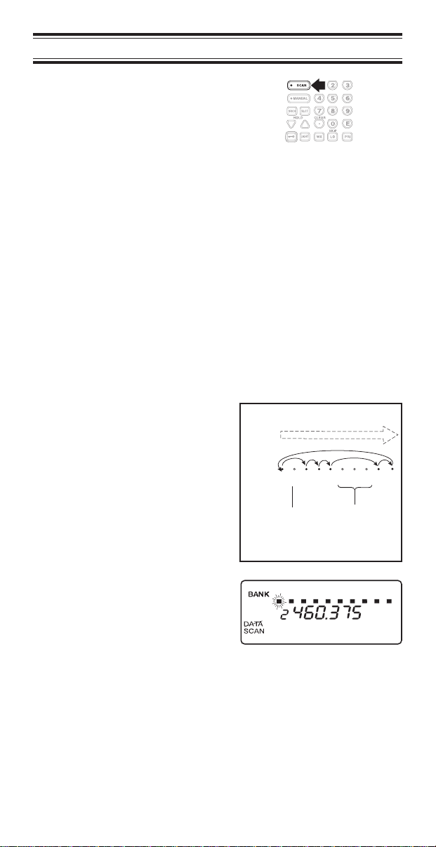
6. Press
searching the bank
R
to begin
12345678910
BANK
TRUNK
you’ve programmed.
Note: You will see
the frequencies
quickly displaying as
your scanner looks
for the data channel
which controls the
system.
Searching a Trunked Bank
Before you Search a Trunked Bank with your scanner,
consider the following:
You can only trunk track one bank at a time.
UseTto toggle between the conventional and
the trunk tracking modes.
Press
review which bank is currently in use. The
appropriate bank icon will flash at the top of the
display for 5 seconds.
while in the Trunk Tracking mode to
D
39
Page 40

If you have programmed frequencies for a trunked system
in one or more of the 10 available banks and you are in
conventional mode, follow these steps to begin trunk
searching:
1. Press
T
.
The bank indicators
begin to flash.
2. Use the keypad to
select the trunked
bank you want. For
example press
2
Note: You will see
the frequencies
quickly displaying as
your scanner looks
for the data channel
which controls the
system.
Once the data
channel is acquired,
the scanner begins
trunk tracking. Talk
group ID’s, which
represent different
service groups, begin
to display.
12345678910
BANK
TRUNK
.
3. PressTagain to
return to conventional
scanning mode.
While searching, you won’t know exactly who the ID’s are
assigned to until you listen awhile or until ID lists are
available in frequency guides or on internet sites. However,
it usually only takes a few minutes to figure out police, fire,
and emergency medical personnel. Other IDs may take
some time, but determining who each ID represents is half
the fun of
TrunkTracker™
.
40
Page 41

ID Hold Mode
During Search mode, you can hold on an ID without
entering it into memory.
1. Press
Search mode.
2. Use the keypad to
enter the ID you want.
3. Press
HOLD
while in
H
again.
H
flashes in the
12345678910
12345678910
display.
4. PressRto return to
Search mode.
Note: The ID Hold mode works in Scan List mode, and
the steps are the same; however,
SRCH
doesn’t
appear in the display.
41
Page 42

ID Lockout
Like conventional scanning, it’s possible to lockout
unwanted traffic. This is particularly important in trunked
systems because in many areas water meters, door
alarms, traffic signals, and other mechanical devices are
assigned IDs just like other users. Also some departments
scramble or encrypt their communications, and you may
want to lock out these unintelligible broadcasts.
To lockout an ID,
press
displays.
The ID is locked out,
and the next active ID
displays. You can
lockout up to 100 IDs.
Note: If you lockout an ID in Search mode, it is also
locked out in Scan List mode. Conversely, if you
lockout an ID while in Scan List mode, it is locked
out in Search mode. For information about Scan
Lists see page 46.
when the ID
O
Restore a Single ID
To unlock a single ID, follow these steps:
1. Press and hold
until you hear two
short beeps.
2. Use
3. Press
4. PressRto return to
(or)
the ID you want to
unlock.
O
The ID is unlocked
and the next locked
ID displays.
the Search mode.
O
to select
.
42
Page 43

Restore all IDs
To unlock all locked out IDs at once, follow these steps:
1. Press and hold
until you hear two
short beeps.
2. Press
3. PressRto return to
E
the IDs at once.
Note: If you unlock all the IDs, then the Scan List
Memory mode displays. Press
stored in your Scan Lists or press
the Search mode. For information about Scan Lists
see page 46.
the Search mode.
O
to unlock all
12345678910
to scan the IDs
S
R
Searching Tips
ID Delay Mode
Use theYkey to select the Delay mode if it’s not
active. This mode holds an ID for 5 seconds while
you wait for a reply. Other groups may use the
system, but your scanner will only look for the ID in
the display.
to return to
Note: If you consistently miss responses while in
ID Delay mode, you may need to change the
default system type or change the fleet map you’re
using.
43
Page 44

Hold Mode
Press
H
This is where the trunk tracking effect is really
noticeable. You can hold a specific talk group,
such as fire department on-scene operations, no
matter which frequency the group uses.
ID Monitor Mode
If you press and hold
beeps, you will select the ID Monitor mode.
begins flashing in the display, and all active talk
group IDs begin to display in succession. You
won’t hear conversations in this mode, but this is
an excellent way to determine which talk groups
are the most active.
to hold on a particular ID in the display.
until you hear two short
R
SRCH
Note: Locked out IDs display during ID Monitor
L/0
mode with the
icon turned on.
Channel Activity Indicators
The
BC 235XLT
visually display a trunked system’s activity when you select
delay, hold, scan etc. You’ll always know which
frequencies are in use and how much communication
traffic is occurring.
Each frequency you program in a trunking bank
corresponds to an activity indicator at the top of your
scanner’s display. The way in which the Activity Indicators
display provide you with information about the system
you’re tracking.
has 20 Channel Activity Indicators to
44
Page 45

■
The indicator which
remains on, even if
when there is no
traffic, represents the
frequency being used
as the data channel.
■
If an indicator turns
on and you don’t hear
a conversation, then
the channel is
probably being used
for a telephone
interconnect call or a
private call. These
calls are not
monitored by your
scanner.
■
The indicator which
flashes when an ID
displays represents
the frequency being
used by the talk
group.
■
If you’re holding on
an ID which isn’t
active, the activity
indicators will turn on
and off as other
groups use the
system.
Note: If more than 20 channels are stored in a
bank, then the indicators represent multiple
channels. For example, if 29 channels are
programmed, the first 9 activity indicators each
represent two channels.
45
Page 46

Scan Lists
Each bank of your
bank or it can be a conventional scanning bank. When you
designate a bank as a trunking bank, your scanner sets up
5 Scan Lists, which are simply lists used to store your
favorite IDs. Each list can contain up to 10 IDs, so you can
store a total of 50 IDs for each trunk tracking bank (500 if
you use all banks as trunking banks!).
Scan Lists help you organize the trunking system users
into categories. For example, you might use List 1 for
police IDs, List 2 for fire department IDs, List 3 for
emergency medical service IDs, etc. Once IDs are stored
in lists, you can scan them like you scan conventional
frequencies. You can program your scan lists either
manually or during trunking search mode.
BC 235XLT
can be a trunk tracking
Programming Scan Lists Manually
1. Select the Trunking
bank you want.
2. After the scanner
begins trunk tracking,
M
.
press
3. Use
select the Scan List
location you want to
program. For
example, select the
second memory
location in the first
scan list.
and(to
)
12345678910
46
Page 47

4. Enter the Type II ID
you want to store,
and press
E
.
—or—
12345678910
To enter a Type I ID:
a. Enter the fleet
12345678910
number.
b. Press
.
.
c. Enter the subfleet
number, and press
.
E
Note: To clear a mistake while entering an ID,
press
5. PressMor)to
select the next Scan
twice, and start over.
.
12345678910
List location.
6. Press
scanning the lists you
S
to begin
12345678910
have programmed.
If you haven’t
programmed any IDs,
SCAN
displays but
your scanner cannot
stop on an active
conversation.
7. To remove a Scan
List from active
12345678910
scanning, press the
number of the Scan
List on your keypad.
The Scan List
indicator turns off,
and the IDs in that list
are not be scanned.
Note: One Scan List must always be active. If you
try and deactivate all the Scan Lists, Scan List 1
will automatically be active.
47
Page 48

8. To restore a Scan List
to active scanning,
press its number
again.
12345678910
9. Press
Trunk Tracking
Search mode.
to return to
R
To alternate your
display between the
12345678910
trunking repeater
indicators and the
Scan List indicators,
P
.
press
OR
Programming Scan Lists During Search
To select a Scan List location and store an ID during
Search mode, follow these steps:
1. When your scanner
stops on an ID you
want to store, press
.
P
2. Use
)or(
the Scan List memory
location you want,
then press
to select
.
E
12345678910
3. Press
Trunk Tracking
Search mode.
to return to
R
48
Page 49

To let your scanner automatically store an ID in an
available Scan List location, follow these steps:
1. Press
2. Press
E when your
scanner stops on an
ID you want to store.
to return to
R
Trunk Tracking
Search mode.
Deleting a Stored ID
To delete a stored ID:
a. Press
b. Then press
0
.
E
12345678910
12345678910
.
49
Page 50

Fleet Map Programming
If you have programmed a trunk tracking bank and select
, you will see user IDs display on your screen. Since
R
the
BC 235XLT
will appear as numbers. However, if you notice a mix of
odd and even user IDs, for example 6477, 2560, 6481,
6144, 1167, etc., then you are probably monitoring either a
Type I or Hybrid system. See
on page 35.
You may also notice that you’re missing responses when
you hold on an active ID. Unlike Type II systems, Type I/IIi
systems require a Fleet Map that sets specific
Fleet-Subfleet parameters. It’s easy to select a Fleet Map
for your scanner; what isn’t always easy is selecting or
programming a map that matches your particular area.
There are 16 preset Fleet Maps listed in the appendix that
you can choose, and these are usually a good place to
start when setting up a Type I/IIi trunk tracking bank. If you
choose a preset map and still have difficulty following
complete conversations, then you’ll have to program your
own Fleet Map.
Selecting Trunking Programming Mode
defaults to Type II systems, all the IDs
Types of Trunking Systems
To change the system type which your scanner monitors,
you must be in the Trunking Programming mode. To select
this mode, follow these steps:
If you are in Conventional Scan mode:
1. Press and hold
T
.
12345678910
BANK
TRUNK
You’ll hear two short
beeps and
TRUNK
BANK
will begin to
and
flash in the display.
2. Select the trunking
bank you want to
program.
50
Page 51

If you are in Trunking Scan mode:
1. Press
to return to
T
conventional mode if
you have been
monitoring a trunking
bank.
2. Press and hold
until you hear two
T
BANK
TRUNK
short beeps.
You’ll hear two short
BANK
beeps and
TRUNK
will begin to
and
flash in the display.
3. Select the trunking
bank you want to
program.
Selecting a Preset Fleet Map
1. Select the Trunking
Programming mode
and the bank you
want to change.
BANK
TRUNK
12345678910
12345678910
12345678910
2. Press
3. Use
E1
)or(
.
4. Press
5. Use
)or(
the map you want.
For example,
D
D
.
to choose
.
to choose
E1P2
12345678910
BANK
TRUNK
12345678910
BANK
TRUNK
.
51
Page 52

6. PressE.
The scanner exits the
Trunking
Programming mode,
acquires the data
channel, and begins
searching using the
preset map you
chose.
Note: You will now begin to see Type I
Fleet-Subfleet IDs. For example, 100-12, 100-9,
000-12, 400-8, etc. See User Defined Fleet Maps
in the Appendix for more information about Type I
IDs.
How do you know if the preset map is correct? You’ll have
to listen to see if you’re following complete conversations.
If not, you should try another preset map.
Programming a Fleet Map
You may want to read User Defined Fleet Maps in the
Appendix before programming a fleet map. It contains a
detailed explanation of Scanner Fleet Map Programming,
as well as a table listing the Fleet Map Size Codes.
1. Select the Trunking
Programming mode
and the bank you
want to change.
2. Press
3. Use
E1
.
4. Press
5. Use
USr
D
)or(
D
)or(
.
.
to choose
.
to choose
52
12345678910
BANK
TRUNK
12345678910
BANK
TRUNK
12345678910
BANK
TRUNK
Page 53

6. PressD.
7. Use
)or(
to select
the size code for the
first block.
8. Press
E
.
The next available
block displays.
9. Repeat Steps 7 and 8
until you have
selected a size code
for each block.
For specifics about
each size code, see
Fleet Map Size
Codes in the
Appendix.
10. PressR.
The scanner exits the
Trunking
Programming mode,
acquires the data
channel, and begins
searching using the
map you’ve
programmed.
12345678910
BANK
TRUNK
12345678910
BANK
TRUNK
Programming a Hybrid System
A Hybrid system is simply a Type I system with some
blocks designated as Type II blocks. To program a Hybrid
system, follow the steps listed in Programming a Fleet Map
in the previous section. However, if you want a block to be
Type II, select Size Code S-0.
When you begin searching a trunking bank with a Hybrid
Fleet Map, you will see both types of system IDs. That is,
Type II IDs usually appear as an even number without a
dash; Type I IDs appear as a three or four digit number,
followed by a hyphen, followed by a one or two digit
number. See page 61 for more information.
53
Page 54

Care and Maintenance
General Use
Turn the scanner off before disconnecting the
power or replacing the batteries.
Always write down the programmed frequencies in
the event of memory loss.
If memory is lost, simply reprogram each channel.
The display shows
there has been a memory loss.
Always press each button firmly until you hear the
entry tone for that key entry.
Location
Do not use the scanner in high-moisture
environments such as the kitchen or bathroom.
Avoid placing the unit in direct sunlight or near
heating elements or vents.
If the scanner receives strong interference or
electrical noise, move it or its antenna away from
the source of the noise. If possible, a higher
elevation, may provide better reception. Also try
changing the height or angle of the antenna.
000.000 in all channels when
Cleaning
Disconnect the power to the unit before cleaning.
Clean the outside of the scanner with a mild
detergent. To prevent scratches, do not use
abrasive cleaners or solvents. Be careful not to rub
the LCD window.
Do not use excessive amounts of water.
54
Page 55

Repairs
Do not attempt any repair. The scanner contains
no user serviceable parts. Contact the Uniden
Customer Service Center or take it to a qualified
repair technician.
Birdies
All radios can receive “birdies” (undesired signals).
If your scanner stops during Scan mode and no
sound is heard, it may be receiving a birdie. Birdies
are internally generated signals inherent in the
electronics of the receiver.
Press
S
to lockout the channel, and then press
O
to resume scanning.
55
Page 56

Troubleshooting
If your
BC 235XLT
is not performing properly, try the
following steps.
Problem Suggestion
Scanner won’t work. 1. Check the connections at both ends of
Improper reception. 1. Check the antenna connection or move
Scan won’t stop. 1. Adjust squelch threshold - refer to
Scan won’t start. 1. Press the
Weather Scan won’t work. 1. Adjust squelch threshold - refer to
the AC Adapter.
2. Turn on the wall switch of your room. You
could be using an outlet controlled by the
wall switch.
3. Move the AC Adapter to another wall
outlet or replace the battery pack.
and reposition the antenna.
2. Move the scanner.
3. You may be in a remote area which could
require an optional multi-band antenna.
Check with your dealer or local
electronics store.
page 15, Setting the Squelch.
2. Check the antenna connection.
3. Check to see if many of the channels are
locked out. If so, the scanner has less
chance of finding an active channel.
4. Review each channel’s frequency to see
if it is still stored in memory and is correct.
5. It’s possible that none of the programmed
frequencies are currently active.
key again.
S
2. Adjust the
3. Check to see if all channels are locked
out.
page 15, Setting the Squelch.
2. Check the antenna.
SQUELCH
control.
56
Page 57

If you experience difficulty while in
try the following steps.
Problem Suggestion
Scanner won’t track the
trunked system.
Scanner won’t stop during
Scan List mode.
Scanner will not acquire
data channel.
Missing replies to
conversations.
Channel Activity Indicators
are flashing but no sound
is heard.
1. May not be a system which can be
tracked by your scanner.
2. Missing the data frequency.
3. Change to a Type 1 Scanner setup.
Review Fleet Map Programming on
page 50.
1. No IDs have been programmed.
2. The IDs you have stored are not active.
1. Adjust the squelch for trunking mode.
See page 37.
2. Missing the frequency used for the data
channel. Check your frequency list.
1. Change to a Type 1 Scanner setup.
Review Fleet Map Programming on
page 50.
2. Try another Preset Fleet Map or Program
your own Fleet Map.
3. Check to see that all of the systems
frequencies have been entered.
1. May be a private or telephone
interconnect call, which are intentionally
blocked by your scanner.
2. The ID in your display is not active.
TrunkTracker™
mode,
If you still cannot get satisfactory results while using your
scanner or if you want additional information, please call or
write the Uniden Parts and Service Division. The address
and phone number are listed in the Warranty at the end of
this manual. If you would like immediate assistance, please
call Customer Service at (800) 297-1023.
If you have internet access, you can visit
www.uniden.comorwww.trunktracker.com
for
additional information.
57
Page 58

Specifications
Certified in accordance with FCC Rules and Regulations
Part 15, Subpart C, as of date of manufacture.
Channels: 300
Banks 10 (30 channels each)
Service Bands: 5–preprogrammed search bands (including
Frequency
Range:
Operating
Temperature:
Scan Rate: 100 channels per second (conventional mode)
Search Rate: 100 steps per second (Normal Search)
Scan Delay: 2 seconds
Audio Output: 180 mW nominal into 8Ω internal speaker
Power
Requirements:
Antenna: Rubber antenna (included)
External Jacks: External earphone, DC 12V power jack
Size: 2
Weight: 12.6 oz.
the NOAA Weather Service band)
29.0–29.7 MHz 10 Meter Amateur Band
29.7–50.0 MHz VHF Low Band
50.0–54.0 MHz 6 Meter Amateur Band
137–144 MHz Military Land Mobile
144–148 MHz 2 Meter Amateur Band
148–174 MHz VHF High Band
Above bands in 5 kHz steps
108–137 MHz Aircraft Band
406–420 MHz Federal Government
420–450 MHz 70 cm Amateur Band
450–470 MHz UHF Standard Band
470–512 MHz UHF “T” Band
806–956 MHz “800” Band
Above bands in 12.5 kHz steps
–20°C to +60°C
300 steps per second (Turbo Search)
30 mW nominal into 32Ω stereo headphone
8 mW nominal into 64Ω earphone
4.8 VDC 800mAh (internal battery or
AD70U AC Adapter)
1/2
in. (W) x 1
3/4
in. (D) x 6
1/2
in. (H)
Features, Specifications, and availability of optional
accessories are all subject to change without notice.
58
Page 59

Appendix
Preset Fleet Maps
Preset Map E1P1
Block
0
1
2
3
4
5
6
7S11
Preset Map E1P3
Block
0
1
2
3
4
5
6
7--
Preset Map E1P5
Block
0
1
2
3
4
5
6
7S4
Size Code
S11
S11
S11
S11
S11
S11
S11
Size Code
S4
S4
S4
S4
S4
S4
S12
Size Code
S4
S4
S12
-S4
S4
S4
Preset Map E1P2
Block
0
1
2
3
4
5
6
7S4
Preset Map E1P4
Block
0
1
2
3
4
5
6
7S4
Preset Map E1P6
Block
0
1
2
3
4
5
6
7--
Size Code
S4
S4
S4
S4
S4
S4
S4
Size Code
S12
-S4
S4
S4
S4
S4
Size Code
S3
S10
S4
S4
S12
--
S12
Preset Map E1P7
Block
0
1
2
3
4
5
6
7S4
Size Code
S10
S10
S11
S4
S4
S4
S4
59
Preset Map E1P8
Block
0
1
2
3
4
5
6
7S4
Size Code
S1
S1
S2
S2
S3
S3
S4
Page 60

Preset Map E1P9
Block
0
1
2
3
4
5
6
7S0
Size Code
S4
S4
S0
S0
S0
S0
S0
Preset Map E1P10
Block
0
1
2
3
4
5
6
7S4
Size Code
S0
S0
S0
S0
S0
S0
S4
Preset Map E1P11
Block
0
1
2
3
4
5
6
7S0
Preset Map E1P13
Block
0
1
2
3
4
5
6
7S0
Preset Map E1P15
Block
0
1
2
3
4
5
6
7--
Size Code
S4
S0
S0
S0
S0
S0
S0
Size Code
S3
S3
S11
S4
S4
S0
S0
Size Code
S4
S4
S4
S11
S11
S0
S12
Preset Map E1P12
Block
0
1
2
3
4
5
6
7S4
Preset Map E1P14
Block
0
1
2
3
4
5
6
7--
Preset Map E1P16
Block
0
1
2
3
4
5
6
7--
Size Code
S0
S0
S0
S0
S0
S0
S0
Size Code
S4
S3
S10
S4
S4
S4
S12
Size Code
S3
S10
S10
S11
S0
S0
S12
60
Page 61

User Defined Fleet Maps
Type I Programming Information
When a Type I system is designed, the address
information for all the IDs is divided into 8 equal sized
blocks, numbered 0–7. When you program your scanner to
track a Type I system, you must select a size code for
each of these blocks. When you have assigned a size
code to all 8 blocks, you’ll have defined the Fleet Map for
the system you’re tracking. Each size code determines the
number of Fleets, Subfleets, and IDs each block will have.
For example, a size code of S-4 has one Fleet, which is
divided into 16 separate Subfleets, and it has a total of 512
individual IDs.
When a block is assigned a size code, the Fleet or Fleets
created within the block are assigned a Type I ID. The way
these IDs display on your scanner depend on the block
number and the block’s size code. When a Type I ID
displays, the leftmost digit represents the block which
contains the ID. The next two digits identify which Fleet is
active, and the last digit(s) identifies the Subfleet.
405-12
Block
(1 digit)
Subfleet
(1 or 2 digits)
Which Fleet
within the Block
(2 digits)
The details concerning how the size codes are selected by
a Type I System designer are highly dependent on the
specific needs of the system’s users. Some organizations
may want many subfleets with only a few radios each,
while another organization may want only a few subfleets
with many radios each. Your task is to program your fleet
map with the same size code assignments as the trunked
system. If you do this accurately, you’ll track all the
Fleet-Subfleet combinations used by the system. In other
words, you’ll hear complete communications while
monitoring a trunked system.
61
Page 62

If you don’t already know the size codes used, you’ll have
to guess at them. But since you don’t have to figure out all
the blocks at once, this isn’t as hard as it seems. Select a
size code for a block, and then press
. Now listen to the
R
communications. If you decide you are receiving most of
the replies to the conversations with IDs assigned to the
block you just programmed, then you’ve probably selected
the right size code and can work on the next block of the
map.
Finally, for most public safety systems there are some size
codes which are more common. S-3 and S-4 are probably
the most common, followed by S-10, S-11, and S-12.
Fleet Map Size Codes
Size Fleets Subfleets IDs Blocks Used
S–0
S–1 128 4 16 1
S–2 16 8 64 1
S–3 8 8 128 1
S–4 1 16 512 1
S–5 64 4 32 1
S–6 32 8 32 1
S–7 32 4 64 1
S–8 16 4 128 1
S–9 8 4 256 1
S–10 4 8 256 1
S–11 2 16 256 1
S–12 1 16 1024 2
S–13 1 16 2048 4
S–14 1 16 4096 8
Reserves block for Type II IDs
62
Page 63

Size Code Restrictions
If you select size code S-12, S-13, or S-14, there are some
restrictions as to which blocks can be used for these codes.
S-12 can only be assigned to Blocks 0, 2, 4, or 6.
S-13 can only be assigned to Blocks 0 and 4.
S-14 can only be assigned to Block 0.
Since these size codes require multiple blocks, you will be
prompted for the next available block when programming a
Fleet Map. For example, if you assign Block 0 as an S-12,
you will be prompted for b2, the next block available,
instead of b1. And if you assign Block 0 as an S-14, you
would not see another prompt because it uses all available
blocks.
63
Page 64

Page 65

Precautions
Before you use this scanner, please read and observe
the following:
EARPHONE WARNING!
Be sure to use only the recommended optional
monaural earphone (EP009). You may also use a 32Ω
stereo headset. Use of an incorrect earphone or stereo
headset may be potentially hazardous to your hearing.
The output of the phone jack is monaural, but you will
hear it in both headphones of a stereo headset.
Set the volume to a comfortable audio level coming
from the speaker before plugging in the monaural
earphone or a stereo headset of the proper impedance
(32Ω). Otherwise you might experience some
discomfort or possible hearing damage if the volume
suddenly becomes too loud because of the Volume
Control or Squelch Control setting. This may be
particularly true of the type of earphone that is placed
in the ear canal.
WARNING!
Uniden does not represent this unit to be waterproof.
To reduce the risk of fire or electrical shock, do not
expose this unit to rain or moisture.
GENERAL BATTERY WARNING!
Do not short-circuit any Battery.
Do not discard Batteries in a fire; they may explode.
NICKEL-CADMIUM BATTERY WARNING!
When using Nickel-Cadmium Batteries with this
product, take note of the following warnings:
Cadmium is a chemical known to the State of
California to cause cancer.
Do not charge Nickel-Cadmium Batteries with any
charger other than the one supplied with this product.
Using another charger may damage the Batteries, or
cause them to explode.
Nickel-Cadmium Batteries must be disposed of
properly. Residents of Minnesota should contact
1-800-225-PRBA for information concerning
reclamation and disposal of Nickel-Cadmium Batteries.
Residents outside of Minnesota should contact their
local authorities for information concerning reclamation
and disposal of Nickel-Cadmium Batteries.
Uniden®and Bearcat®are registered trademarks of
Uniden America Corporation.
Page 66

Front View
11
1 2 3 4 5 6 7 8 9 10
1
2
BANK
TRUNK
888.8888
888
DATA POLICE FIRE/EMG AIR M RN WX
SCAN SRCH PRI HOLD DLY L /O
BATT
12
3
4
5
6
7
8
9
10
1. DC Power Jack 10. Light
2. Scan Key
3. Manual Key
4. Trunking Key
5. Decimal Key
6. Service Key
7. Limit KeyL/
Down Key
8. Priority Key
Turbo Key
9. Delay Key
S
M
(
P
Y
T
.
C
11. Speaker
12. Display
13. Keypad
14. Enter Key
15. Search Key
16. Hold KeyH/
Up Key
/
17. Lockout Key
18. Data Key
/ Lock Key
K
)
D
13
14
15
16
17
18
E
R
O
Page 67

Top View and Display
19 20 21 22
19. Antenna Connector
20. Earphone Jack
21. Squelch Control
22. On/Off Volume Control
23 24
12345678910
BANK
30
TRUNK
29
DATA POLICE FIRE/EMG AIR MRN WX
SCAN SRCH PRI HOLD DLY L/O
888.8888
888
28 27
23. Channel Display
24. Frequency Display
25. Bank/Activity Indicators
26. Battery Low Indicator
27. Keypad Lockout Indicator
28. Mode Indicators
29. Priority Channel Indicator
30. Bank/Trunk Indicators
BATT
25
26
Page 68

One Year Limited Warranty
Important: Evidence of original purchase is required for
WARRANTOR: UNIDEN AMERICA CORPORATION (“Uniden”)
ELEMENTS OF WARRANTY: Uniden warrants, for one year, to
the original retail owner, this Uniden Product to be free from
defects in materials and craftsmanship with only the limitations or
exclusions set out below.
WARRANTY DURATION: This warranty to the original user shall
terminate and be of no further effect 12 months after the date of
original retail sale. The warranty is invalid if the Product is (A)
damaged or not maintained as reasonable or necessary, (B)
modified, altered, or used as part of any conversion kits,
subassemblies, or any configurations not sold by Uniden, (C)
improperly installed, (D) serviced or repaired by someone other
than an authorized Uniden service center for a defect or
malfunction covered by this warranty, (E) used in any conjunction
with equipment or parts or as part of any system not
manufactured by Uniden, or (F) installed or programmed by
anyone other than as detailed by the Operating Guide for this
product.
STATEMENT OF REMEDY: In the event that the product does
not conform to this warranty at any time while this warranty is in
effect, warrantor will repair the defect and return it to you without
charge for parts, service, or any other cost (except shipping and
handling) incurred by warrantor or its representatives in
connection with the performance of this warranty. THE LIMITED
WARRANTY SET FORTH ABOVE IS THE SOLE AND ENTIRE
WARRANTY PERTAINING TO THE PRODUCT AND IS IN LIEU
OF AND EXCLUDES ALL OTHER WARRANTIES OF ANY
NATURE WHATSOEVER, WHETHER EXPRESS, IMPLIED OR
ARISING BY OPERATION OF LAW, INCLUDING, BUT NOT
LIMITED TO ANY IMPLIED WARRANTIES OF
MERCHANTABILITY OR FITNESS FOR A PARTICULAR
PURPOSE. THIS WARRANTY DOES NOT COVER OR
PROVIDE FOR THE REIMBURSEMENT OR PAYMENT OF
INCIDENTAL OR CONSEQUENTIAL DAMAGES. Some states
do not allow this exclusion or limitation of incidental or
consequential damages so the above limitation or exclusion may
not apply to you.
LEGAL REMEDIES: This warranty gives you specific legal rights,
and you may also have other rights which vary from state to
state. This warranty is void outside the United States of America.
PROCEDURE FOR OBTAINING PERFORMANCE OF
WARRANTY: If, after following the instructions in this Operating
Guide you are certain that the Product is defective, pack the
Product carefully (preferably in its original packaging). Include
evidence of original purchase and a note describing the defect
that has caused you to return it. The Product should be shipped
freight prepaid, by traceable means, or delivered, to warrantor at:
Uniden America Corporation
Parts and Service Division
4700 Amon Carter Boulevard
Fort Worth, TX 76155
(800) 297-1023, 8:00 a.m. to 5:00 p.m., Central, Monday
through Friday
warranty service.
Page 69

Covered under one or more of the following U.S. patents:
RE31,523 4,057,760 4,092,594 4,100,497 4,114,103
4,156,193 4,157,505 4,179,662 4,219,821 4,270,217
4,398,304 4,409,688 4,455,679 4,461,036 4,521,915
4,597,104 4,627,100 4,841,302 4,888,815 4,932,074
4,947,456 5,014,348 5,199,109 5,408,692 5,428,826
5,438,688 5,448,256 5,465,402 5,471,660 5,483,684
5,548,832 5,551,071
and other patents pending.
©1997 Uniden America Corporation. All rights reserved.
Printed in the Philippines
 Loading...