


USER GUIDE & SERVICE MANUAL
SAFETY • INSTALLATION & INTEGRATION • OPERATING INSTRUCTIONS • MAINTENANCE • SERVICE
RIGHT PRODUCT. RIGHT PLACE. RIGHT TEMPERATURE. SINCE 1962.
1000 Series • CLR1215 • 15" Clear Ice Maker
USER GUIDE & SERVICE MANUAL
u-line.com
Table of Contents
Intro
Safety
Safety and Warning
Disposal And Recycling
Installation
Environmental Requirements
Electrical
Cutout Dimensions
Product Dimensions
Side by Side Installation
Water Hookup
Drain
Anti-Tip Bracket
General Installation
Grille / Plinth Installation
Door Swing
Door Adjust
Maintenance
Cleaning
Cleaning Condenser
Extended Non-Use
Operating Instructions
First Use
Control Operation
Ice
Sabbath Mode
Airflow and Product Loading
Service
Troubleshooting
Wire Diagram
Product Liability
Warranty Claims
Parts
Ordering Replacement Parts
System Diagnosis Guide
Compressor Specifications
Troubleshooting Extended
Control Operation - Service
Thermistor
Defrost
Warranty
USER GUIDE
u-line.com
WELCOME TO U-LINE
Congratulations on your U-Line purchase. Your product comes from a company with over five decades of premium modular ice making, refrigeration, and wine preservation experience. U-Line creates products focused on functionality, style, and inspired innovations — paying close attention to even the smallest details. Applications include residential, outdoor, ADA height compliant, marine, and commercial. Complete product categories include Beverage Centers, Wine Refrigerators, Ice Machines, Refrigerators, Freezers, and Dispensers.
Our advanced refrigeration systems, large and flexible capacities, and Built-In to Stand Out® clean integrated look allow you to preserve the right product, in the right place, at the right temperature. Since 2014, U-Line has been part of the Middleby family of brands. All products are designed, engineered, and assembled in Milwaukee, Wisconsin, USA, and select products are available worldwide.
PRODUCT INFORMATION
Looking for additional information on your product? User Guides, Spec Sheets, CAD Drawings, Compliance Documentation, and Product Warranty information are all available for reference and download at u-line.com.
PROPERTY DAMAGE / INJURY CONCERNS
In the unlikely event property damage or personal injury is suspected related to a U-Line product, please take the following steps:
1.U-Line Customer Care must be contacted immediately at +1.414.354.0300.
2.Service or repairs performed on the unit without prior written approval from U-Line is not permitted. If the unit has been altered or repaired in the field without prior written approval from U-Line, claims will not be eligible.
GENERAL INQUIRIES
U-Line Corporation
8900 N. 55th Street
Milwaukee, Wisconsin 53223 USA Monday - Friday 8:00 am to 4:30 pm CST T: +1.414.354.0300
Email: sales@u-line.com u-line.com
SERVICE & PARTS ASSISTANCE
Monday - Friday 8:00 am to 4:30 pm CST T: +1.800.779.2547
Service Email: onlineservice@u-line.com
Parts Email: onlineparts@u-line.com
CONNECT WITH US
Designed, engineered and assembled in WI, USA
Introduction |
3 |
USER GUIDE
u-line.com
SAFETY • INSTALLATION & INTEGRATION • OPERATING INSTRUCTIONS • MAINTENANCE • SERVICE
Safety and Warning
NOTICE
Please read all instructions before installing, operating, or servicing the appliance.
Use this appliance for its intended purpose only and follow these general precautions with those listed throughout this guide:
SAFETY ALERT DEFINITIONS
Throughout this guide are safety items labeled with a
Danger, Warning or Caution based on the risk type:
! DANGER
Danger means that failure to follow this safety statement will result in severe personal injury or death.
! WARNING
Warning means that failure to follow this safety statement could result in serious personal injury or death.
! CAUTION
Caution means that failure to follow this safety statement may result in minor or moderate personal injury, property or equipment damage.
4 |
Safety and Warning 1 |

USER GUIDE
u-line.com
SAFETY • INSTALLATION & INTEGRATION • OPERATING INSTRUCTIONS • MAINTENANCE • SERVICE
Disposal and Recycling
! DANGER
RISK OF CHILD ENTRAPMENT. Before you throw away your old refrigerator or freezer, take off the doors and leave shelves in place so children may not easily climb inside.
If the unit is being removed from service for disposal, check and obey all federal, state and local regulations regarding the disposal and recycling of refrigeration appliances, and follow these steps completely:
1.Remove all consumable contents from the unit.
2.Unplug the electrical cord from its socket.
3.Remove the door(s)/drawer(s).
5 |
Disposal and Recycling 1 |
USER GUIDE
u-line.com
SAFETY • INSTALLATION & INTEGRATION • OPERATING INSTRUCTIONS • MAINTENANCE • SERVICE
Environmental Requirements
This model is intended for indoor/interior applications only and is not to be used in installations that are open/ exposed to natural elements.
This unit is designed to operate between 50°F (10°C) and 100°F (38°C). Higher ambient temperatures may reduce the unit’s ability to reach low temperatures and/or reduce ice production on applicable models.
For best performance, keep the unit out of direct sunlight and away from heat generating equipment.
In climates where high humidity and dew points are present, condensation may appear on outside surfaces. This is considered normal. The condensation will evaporate when the humidity drops.
! CAUTION
Damages caused by ambient temperatures of 40°F (4°C) or below are not covered by the warranty.
6 |
Environmental Requirements 1 |
USER GUIDE
u-line.com
Electrical
! WARNING
SHOCK HAZARD — Electrical Grounding Required. Never attempt to repair or perform maintenance on the unit until the electricity has been disconnected.
Never remove the round grounding prong from the plug and never use a two-prong grounding adapter.
Altering, cutting or removing power cord, removing power plug, or direct wiring can cause serious injury, fire, loss of property and/or life, and will void the warranty.
Never use an extension cord to connect power to the unit.
Always keep your working area dry.
NOTICE
Electrical installation must observe all state and local codes. This unit requires connection to a grounded (three-prong), polarized receptacle that has been placed by a qualified electrician.
The unit requires a grounded and polarized 115 VAC, 60 Hz, 15A power supply (normal household current). An individual, properly grounded branch circuit or circuit breaker is recommended. A GFCI (ground fault circuit interrupter) is usually not required for fixed location
appliances and is not recommended for your unit because it could be prone to nuisance tripping. However, be sure to consult your local codes.
See CUTOUT DIMENSIONS for recommended receptacle location.
Electrical |
7 |
USER GUIDE
u-line.com
SAFETY • INSTALLATION & INTEGRATION • OPERATING INSTRUCTIONS • MAINTENANCE • SERVICE
Cutout Dimensions
PREPARE SITE
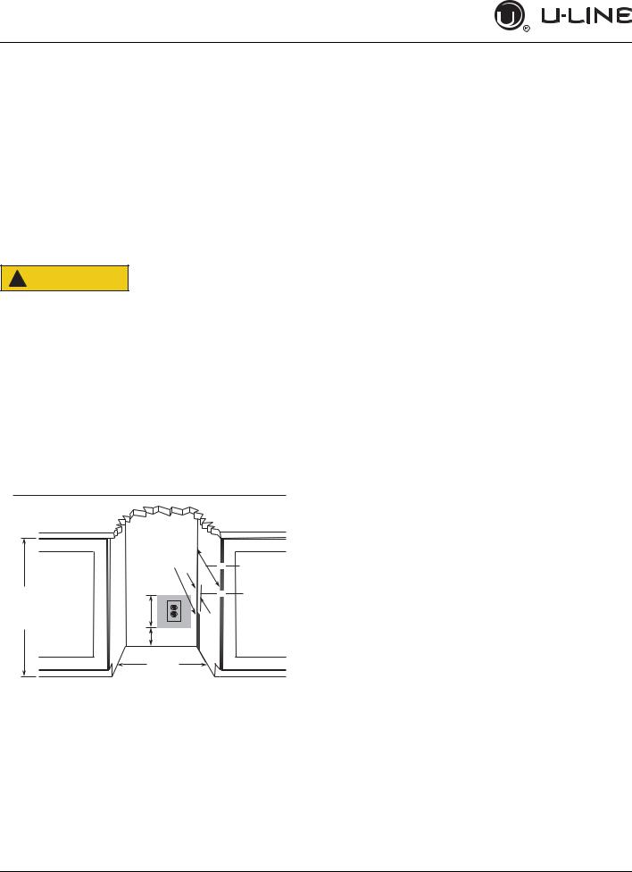
Your U-Line product has been designed for either freestanding or built-in installation. When built-in, your unit does not require additional air space for top, sides, or rear. However, the front grille must NOT be obstructed, and clearance is required for an electrical connection in the rear.
! CAUTION
Unit can NOT be installed behind a closed cabinet door.
If you would like to align the face of the unit with other adjacent cabinet doors, you may need to alter the wall just behind the drain connection on the unit to accommodate the drain.
CUTOUT DIMENSIONS
|
Preferred location |
|
|
for water line and |
|
|
eletrical outlet is in |
|
|
adjacent cabinet. |
|
34-1/4" |
|
|
(870 mm) |
7" |
|
to |
||
(178 mm) |
||
35" |
||
|
||
(889 mm) |
4" |
|
|
||
|
(102 mm) |
|
|
15-1/4" |
|
|
(387 mm) |
24" (610 mm)
5/8" (16 mm)
8 |
Cutout Dimensions 1 |
USER GUIDE
u-line.com
SAFETY • INSTALLATION & INTEGRATION • OPERATING INSTRUCTIONS • MAINTENANCE • SERVICE
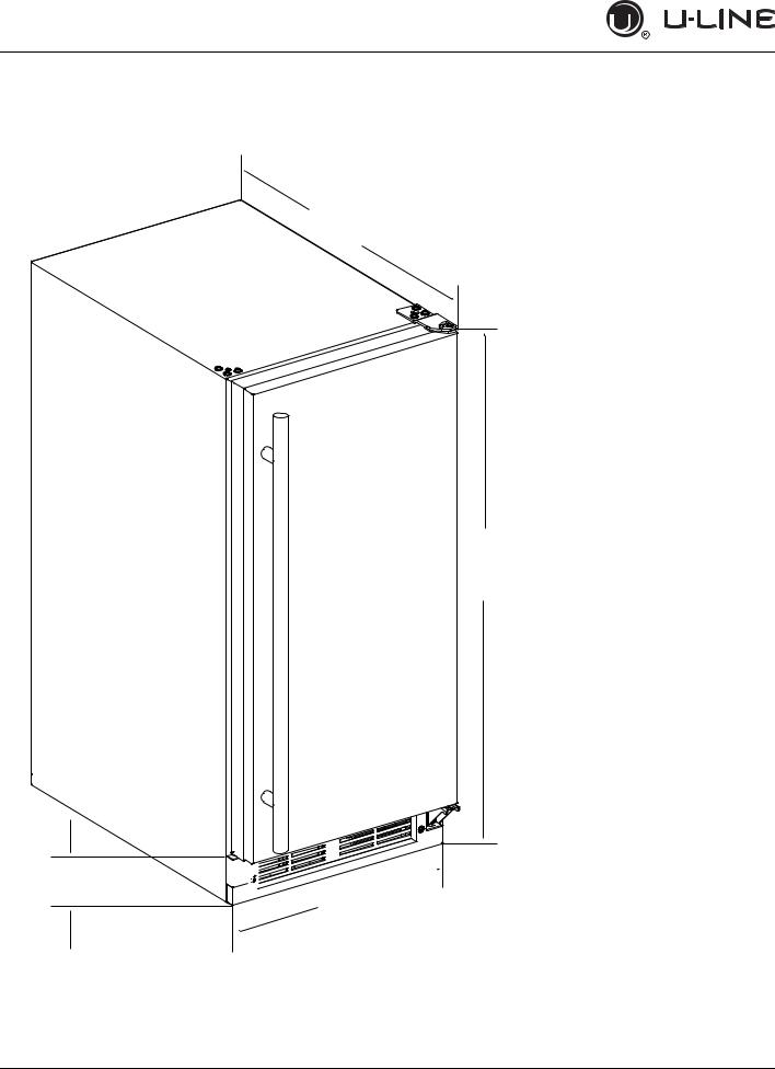
Product Dimensions
Not Including Handle 23-1/4" (591 mm)
34-1/8" to 35-1/8"
(867 mm to 892 mm)
3-9/16" (91 mm) 


 14-15/16" (379 mm)
9 |
Product Dimensions 1 |
USER GUIDE
Side-by-Side Installation
Two units may be installed side-by-side.
Cutout width for a side-by-side installation is the cutout dimension of a single unit times two.
No trim kit is required. However, 1/4" (6 mm) of space needs to be maintained between the units to ensure unobstructed door swing.
Units must operate from separate, properly grounded electrical receptacles placed according to each unit’s electrical specifications requirements.
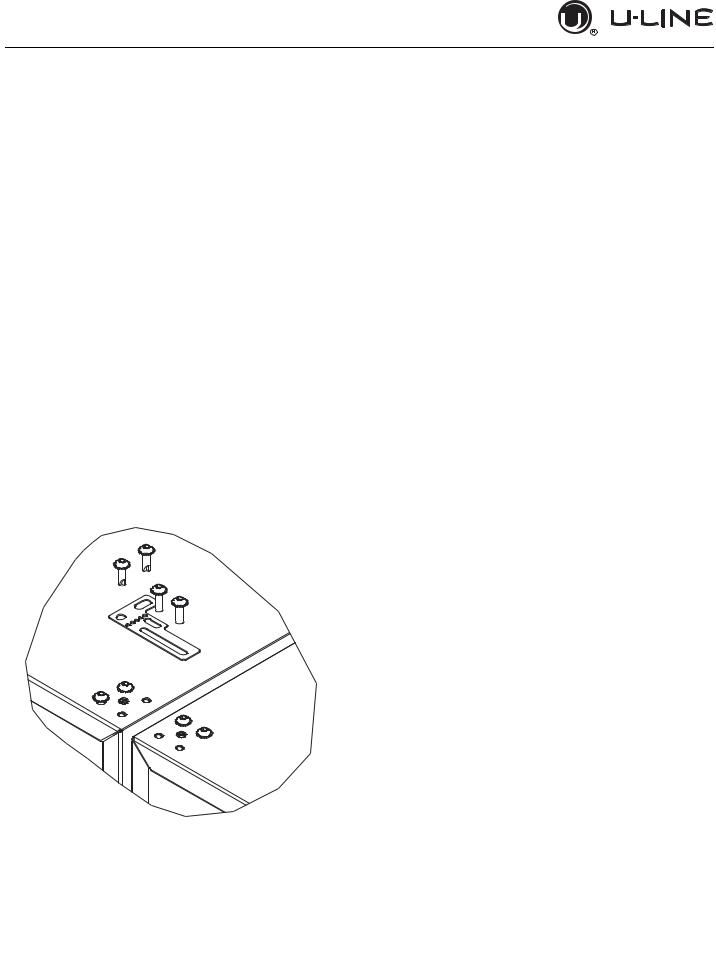
Side-by-Side Installation with Bracket
1.Slide both units out so screws on top of units are easily accessible.
2.Remove screws as shown below.
3.Place bracket over holes and attach to unit with two screws removed in step 2 using a T-25 Torx driver. Tighten screws fully.
4.Gently push units into position. Be careful not to entangle the electrical cord or water line, if applicable.
5.Re-check the leveling, from front to back and side to side. Make any necessary adjustments. The unit’s top surface should be approximately 1/8" (3 mm) below the countertop.
Side-by-Side Installation |
10 |
USER GUIDE
u-line.com
SAFETY • INSTALLATION & INTEGRATION • OPERATING INSTRUCTIONS • MAINTENANCE • SERVICE
Water Hookup
! CAUTION
PREPARE PLUMBING
The water valve uses a standard 1/4” (6.35 mm) compression fitting.
U-Line recommends using accessory water hookup kit - Part # 80-54674-00. The kit includes a 10’ (3 m) braided flexible water supply line and a brass hose fitting.
! WARNING
Prior to installation, determine if this product contains a gravity style drain or factory installed drain pump. Products without a drain pump may only use a gravity style drain. Failure to connect water supply or drain line connections properly may result in water leakage, personal injury, and/or property damage. Disconnect power and turn off water to the unit before attempting to alter these connections. These connections are the responsibility of the owner and must be connected per local plumbing code. If you are uncertain of how to safely and properly install this product, contact a licensed plumber.
Water Supply Connection
! WARNING
Connect to potable water supply only.
! CAUTION
Review, obey, and understand the local plumbing codes before you install your unit. Connect to the cold water supply. The water pressure should be between 20 and 120 psi (138 and 827 kPa). The water line MUST have a shutoff valve on the supply line.
Do not use any plastic water supply line. The line is under pressure at all times. Plastic may crack or rupture with age and cause damage to your home.
Do not use tape or joint compound when attaching a braided flexible water supply line that includes a rubber gasket. The gasket provides an adequate seal – other materials could cause blockage of the valve.
Failure to follow recommendations and instructions may result in damage and/or harm, flooding or void the product warranty.
! CAUTION
Turn off water supply and disconnect electrical supply to unit prior to installation.
Use caution when handling back panel. The edges could be sharp.
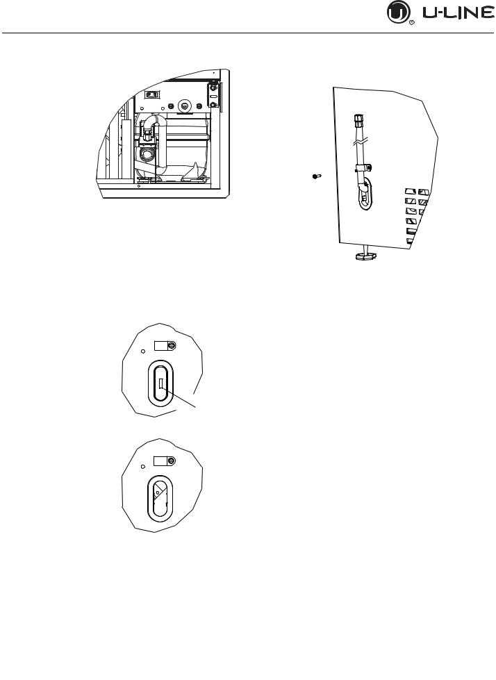
1.Turn off water supply and disconnect electrical supply to product prior to attempting installation.
2.Remove the grille/access panel in the front and the back panel.
11 |
Door Swing 1 |
USER GUIDE
u-line.com
SAFETY • INSTALLATION & INTEGRATION • OPERATING INSTRUCTIONS • MAINTENANCE • SERVICE
3. Locate water |
|
|
8. Install retaining clip. |
|
valve in the front of the unit and thread water supply line through.
NOTICE Route the water supply line
through the unit so it does not come into contact with any internal components other than the solenoid valve. Normal operation creates some vibration. A water supply line contacting an internal component or cabinet wall can cause excessive noise during operation or damage to the line.
4. On the back panel, break away filler feature in bushing with flat screwdriver.
 Remove
ZLWK ɠDW screwdriver
5. Thread water line through back panel hole (with bushing) and connect to cold water supply line.
6.Turn on water supply and check for leaks.
7.Reinstall back panel and grille/front access panel.
12 |
Door Swing 2 |
USER GUIDE
u-line.com
SAFETY • INSTALLATION & INTEGRATION • OPERATING INSTRUCTIONS • MAINTENANCE • SERVICE
Drain
Model numbers including “-00” or “-07” do not include a factory installed drain pump.
Model numbers including “-40” or “-47” include a factory installed drain pump.
DRAIN CONNECTION
! CAUTION
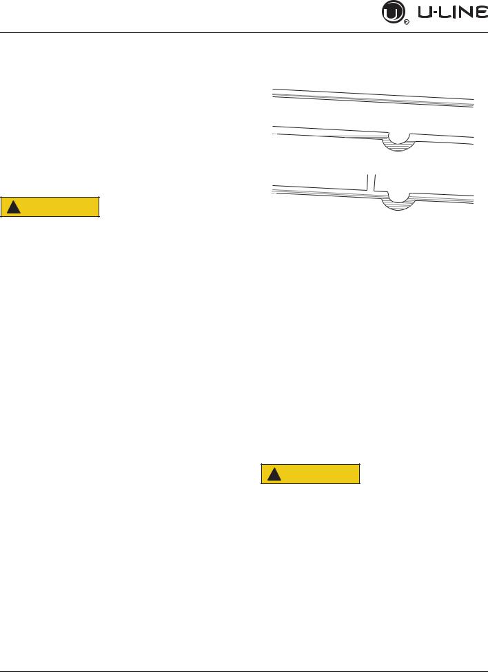
GRAVITY DRAIN
Normal
Proper Drain
With Trap
Poor Drainage, Water Will Back Up
With Trap and Vent
Proper Drain
If your U-Line unit did not come with a factory installed drain pump you must use a gravity style drain connection. For assistance in determining if your unit has a pump please contact U-Line. The floor drain must be large enough to accommodate drainage from all attached drains. Follow these guidelines when installing drain lines to prevent water from flowing back into the ice maker storage bin and/ or potentially flowing onto the floor, which may result in personal injury or property damage.
NOTICE
A gravity drain may be used if:
Drain line has at least a 1" drop per 48" (approximately 2 cm drop per 100 cm) of run.
Drain line does not create traps and is vented per local code.
1.Cut the pre-installed drain tube to length.
2.Connect to your local plumbing per the local code.
Drain can NOT be located directly below the unit. Unit has a solid base that will not allow the unit to drain below itself.
There is a possibility that hose connections may have loosened during shipment.
Verify all connections and fittings are free from leaks.
3.If necessary, insulate drain line to prevent condensation.
! CAUTION
Failure to connect water supply or drain line connections properly can result in personal injury and property damage. Gravity drain connections must be routed downward from the rest of the unit at the rate of 1/4" per foot (1 cm per 50 cm).
13 |
Drain 1 |
USER GUIDE
u-line.com
SAFETY • INSTALLATION & INTEGRATION • OPERATING INSTRUCTIONS • MAINTENANCE • SERVICE
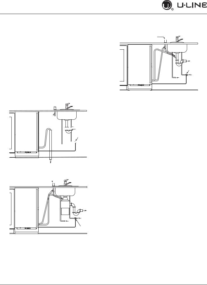
FACTORY INSTALLED DRAIN PUMP
If your drain line will run up to a stand pipe, disposal or spigot assembly, or does not otherwise meet the requirements for a gravity drain, you may have ordered a pre-installed U-Line P60 drain pump.
If you need to install a P60 drain pump into your unit, see DRAIN PUMP section in the User Manual.
See below for typical installations requiring a drain pump.
Stand Pipe
P60 Pump Required


 Waste
Waste
6KXW 2ɞ
Valve


 Cold
Cold


 Hot Water
Water
Waste
Disposal Assembly
P60 Pump Required
Y-Branch Tailpiece
P60 Pump Required
Air Gap
(Optional Hook-Up) 


|
Waste |
|
6KXW 2ɞ |
|
Valve |
|
Cold |
Hot |
Water |
Water |
|
NOTICE |
|
The maximum lift for the P60 drain pump is
10 feet. This must be done as close to the rear of the unit as possible.
Air Gap 
(Optional Hook-Up) 

|
Waste |
|
Cold |
Hot |
Water |
Water |
|
|
6KXW 2ɞ |
|
Valve |
14 |
Drain 2 |
USER GUIDE
u-line.com
SAFETY • INSTALLATION & INTEGRATION • OPERATING INSTRUCTIONS • MAINTENANCE • SERVICE
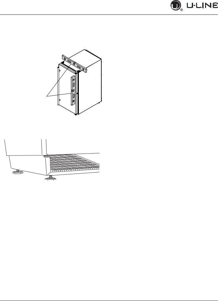
Anti-Tip Bracket
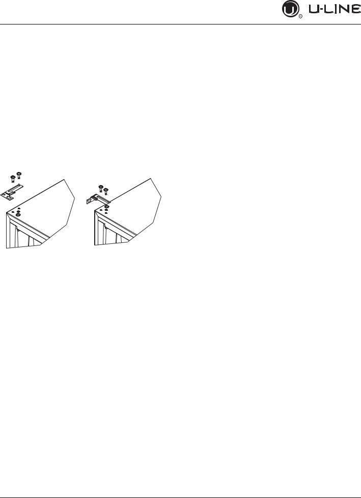
1.Slide unit out so screws on top of unit are easily accessible.
2.Remove the two screws from the opposite side of the hinge assembly using a T-25 Torx driver (see below).
NOTE: 1224 models shown with four screw. 1215 models only have three screws, but same screws are used in both applications.
3.Place bracket (part #14154) over holes and attach to unit with two screws removed in step 2 using a T-25 Torx driver. Tighten screws fully.
4.Gently push unit into position. Be careful not to entangle the electrical cord or water line, if applicable.
5.Check to be sure the unit is level from front to back and side to side. Make any necessary adjustments. The unit’s top surface should be approximately 1/8" (3 mm) below the countertop.
6.Secure bracket into adjoining surface.
15 |
Anti-Tip Bracket 1 |
USER GUIDE
u-line.com
SAFETY • INSTALLATION & INTEGRATION • OPERATING INSTRUCTIONS • MAINTENANCE • SERVICE
General Installation |
INSTALLATION |
LEVELING INFORMATION |
1. Plug in the power/electrical cord. |
|
1. Use a level to confirm the unit is level. Level should be placed along top edge and side edge as shown.
1
2.If the unit is not level, adjust the legs on the corners of the unit as necessary.
 Turn to Adjust
3.Confirm the unit is level after each adjustment and repeat the previous steps until the unit is level.
INSTALLATION TIP
If the room floor is higher than the floor in the cutout opening, adjust the rear legs to achieve a total unit rear height of 1/8" (3 mm) less than the opening’s rear height. Shorten the unit height in the front by adjusting the front legs. This allows the unit to be gently tipped into the opening. Readjust the front legs to level the unit after it is correctly positioned in the opening.
2.Gently push the unit into position. Be careful not to entangle the cord or water and drain lines.
3.Re-check the leveling, from front to back and side to side. Make any necessary adjustments. The unit’s top surface should be approximately 1/8" (3 mm) below the countertop.
4.Install the anti-tip bracket.
5.Remove interior packing material and wipe out the inside of the unit with a clean, water-dampened cloth.
16 |
General Installation 1 |
 Loading...