

Page 1
Page 2

- 1 -
PREFACE
Thank you for purchasing the TV-IP322P SecurView™ Outdoor PoE
Megapixel Day/Night Internet Camera, a standalone system that can be
connected directly to an Ethernet or Fast Ethernet network.
The camera is equipped with a 2-megapixel CMOS sensor, allowing you
to capture high quality image with the resolution of up to 1280 x 1024.
Additionally, the camera features the IR (Infrared) LEDs and ICR function
(IR Cut Filter). The ICR function enables the camera to capture the clear
image under sunlight and increase the amount of light for IR LEDs in the
dark by changing the filter automatically. The camera also provides the
audio and microphone ports, allowing you to transfer sound from/to the
camera.
Compared to the conventional PC Camera, this camera features a built-in
CPU and web-based solutions that can provide a cost-effective solution
to transmit the real-time high-quality video images and sounds
synchronously for monitoring. The camera can be managed remotely, so
that you can use a web browser to access and control it from any
desktop/notebook computer over the Intranet or Internet.
Compliant with IEEE802.3af PoE (Power over Ethernet) standard, the
camera provides you with more flexibility of camera installation
according to your application. The camera can be powered by the
Ethernet, so that you can place the camera anywhere without a power
outlet supported.
The trouble-free installation procedures and web-based interface allow
you to integrate it into your network fast and easy. With comprehensive
applications supported, the Internet camera is your best solution for
remote monitor, high quality, and high performance video images.
Page 3

- 2 -
This Advanced Installation Guide provides you with the instructions and
illustrations on how to use your camera, which includes:
Chapter 1 Introduction to Your Camera describes the features of the
camera. You will also know the components and functions
of the camera.
Chapter 2 Hardware Installation helps you install the camera
according to your application environment. You can use
this camera at home, at work, at any where you want.
Chapter 3 Accessing the Camera lets you start using your camera
without problem. The camera can be set up easily and work
within your network environment instantly.
Chapter 4 Configuring the Camera guides you through the
configuration of the camera using the Web browser on
your PC.
Chapter 5 Using SecurView™ Pro shows you the detail instructions on
operating SecurView™ Pro software.
Chapter 6 How to Access the Camera Behind a Router provides the
instruction how to setup your DDNS.
Chapter 7 Appendix provides the specification of the camera and
some useful information for using your camera.
NOTE The illustrations and configuration values in this guide are for reference
only. The actual settings depend on your practical application of the
camera.
NOTE All trademarks and logos are the property of the respective trademark
owners.
Page 4

- 3 -
Contents
PR E F AC E
CH APTER 1
IN T R O D U C T I O N TO YO U R CAM E RA
1.1 CHECKING THE PACKAGE CONTENTS ............................................. 5
1.2 GETTING TO KNOW THE CAMERA ................................................. 6
1.3 FEATURES AND BENEFITS ............................................................ 9
1.4 SYSTEM REQUIREMENT ............................................................ 12
CH APTER 2
HA RDW ARE IN S T ALLATION
2.1 ASSEMBLING THE CAMERA MOUNTING BRACKET .......................... 14
2.2 MOUNTING THE CAMERA ......................................................... 14
2.3 INSTALLING THE MEMORY CARD ................................................ 15
2.4 APPLICATIONS OF THE CAMERA.................................................. 16
CH APTER 3
AC C ES SI NG THE CAM E RA
3.1 USING IP SETUP ...................................................................... 17
3.2 ACCESSING TO THE CAMERA ...................................................... 22
3.3 CONFIGURING THE IP ADDRESS OF THE COMPUTER ....................... 25
CH APTER 4
CO N F I G U RING THE CAMER A
4.1 USING THE WEB CONFIGURATION .............................................. 26
4.2 USING SMART WIZARD ............................................................ 27
4.3 BASIC SETUP .......................................................................... 30
4.4 NETWORK SETTINGS ................................................................ 35
4.5 SETTING UP VIDEO & AUDIO ..................................................... 41
4.6 EVENT SERVER CONFIGURATION ................................................ 49
4.7 MOTION DETECT..................................................................... 57
Page 5

- 4 -
4.8 EVENT CONFIGURATION ........................................................... 58
4.9 TOOLS ................................................................................... 64
4.10 RS-485 ................................................................................. 66
4.11 SETTING UP THE SD CARD ......................................................... 70
4.12 INFORMATION ........................................................................ 72
CH APTER 5
SE C U R VI E W™ PR O SO F T W ARE
5.1 INSTALLATION ......................................................................... 75
5.2 USING SECURVIEW™ PRO ........................................................ 78
CH APTER 6
Ho w to a c c e s s t h e c a m e r a b e h i n d a R ou t e r
Appendi x
A.1 SPECIFICATION ...................................................................... 117
A.2 GPIO TERMINAL APPLICATION ................................................ 119
A.3 BANDWIDTH REFERENCE GUIDE ............................................... 120
A.4 GLOSSARY OF TERMS ............................................................. 121
Limit ed W a r r a n t y
Page 6

- 5 -
CHAPTER 1
INTRODUCTION TO YOUR CAMERA
1.1 Checking the Package Contents
Unpack the package and check the items contained in the package
carefully. You should have the following:
1 x TV-IP322P
1 x Multi-Language Quick Installation Guide
1 x CD-ROM (Utility & User’s Guide)
1 x Desiccant **
2 x GPIO Connector
1 x Spiral Cable Wrap
1 x Camera Mounting Bracket Kit*
1 x Power Adapter (12V DC, 1.5A)
NOTE Once any item contained is damaged or missing, contact the authorized
dealer of your locale.
* The provided screws included: (1) screws and washers for assembling the camera
shield; (2) expansion screws for mounting the camera to the wall.
** The camera provides two packs of desiccant: one pack is pre-installed inside the
camera compartment before shipment; the extra pack is provided for replacement
while you open the back cover in the future.
Page 7
- 6 -
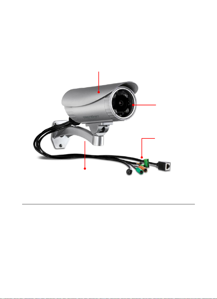
1.2 Getting to Know the Camera
Lens Assembly
with IR LEDs
Shield* is used to protect the
camera during inclement weather.
Camera Stand
Connectors
Power, Audio, Mic,
GPIO, LAN
The Camera and the Shield
* There are various positions of screw hole on the shield, allowing you to move the shield
forward/backward according to your needs. For example, it will protect the camera lens
well during rainy day by adjusting the shield forward.
Page 8

- 7 -
The Connectors
The camera's connectors are collected into a bundle of cable on the back
panel of the camera, allowing you to connect the external devices in a
well-ordered way while you are installing the camera onto the wall (or
ceiling).
Power: Connects the power adapter to supply power to the
camera.
GPIO: Connects the external device that features additional
controlling function, such as motion detection, event triggering,
alarm notification, and a variety of external control functions.
NOTE Before connecting the external device for GPIO function, you
have to attach the provided external GPIO connectors to the
device.
Audio Out: Connects an external audio device (such as the active
speaker) to deliver sound via the camera.
Mic In: Connects an external microphone to receive the on-the-
spot sound where the camera is installed.
Page 9

- 8 -
LAN: Plugs the provided Ethernet cable to connect to your local
area network (LAN). The LAN port of the camera supports the
NWay protocol so that the camera can detect the network speed
automatically.
Page 10

- 9 -
1.3 Features and Benefits
H.264/MPEG4/MJPEG Multi-codec Supported
The camera provides you with excellent images by the
H.264/MPEG4/ MJPEG multi-codec selectable technology,
allowing you to adjust image size and quality, and bit rate
according to the networking environment.
High Resolution Surveillance
Equipped with a megapixel CMOS sensor, the high performance
camera is designed for your professional surveillance and security
applications. The image resolution is up to 1280 x 1024. In
addition, the minimum illumination of the sensor is 0 lux,
providing a truly day & night functions that allows you to capture
image even in low-light conditions.
Multiple Profiles Supported
The camera supports multiple profiles simultaneously, so that you
can separately set up different image settings (such as image
quality and frame rate) for the video types of the camera: H.264,
MPEG4, MJPEG, and 3GPP.
Flexible Audio Capability
The camera allows you to connect the external microphone to
receive on-the-spot audio via the Internet, allowing you to
monitor the on-site voice. In addition, you can connect an external
active speaker to the camera to speak through the camera
(supporting mono audio only).
Supports RTSP
The camera supports RTSP (Real Time Streaming Protocol), which
is a technology that allows you to view streaming media via the
network. You can view the real-time video with the Quick Time
player or RealPlayer. To view the real-time streaming image on
your computer, open the Web browser and enter the RTSP link:
rtsp://(IP address of the camera)/mpeg4
Page 11

- 10 -
Remote Control Supported
By using a standard Web browser or the bundled SecurView™ Pro
software application, the administrator can easily change the
configuration of the camera via Intranet or Internet.
In addition, the camera can be upgraded remotely when a new
firmware is available. The users are also allowed to monitor the
image and take snapshots via the network.
I/O Connectors and RS-485 Provided
The I/O connectors (IN/OUT) of the camera provide the physical
interface to send and receive digital signals to a variety of external
alarm devices (such as motion detection, event triggering, alarm
notification, and a variety of external control functions).
The pins TX+ & TX- of the I/O connectors are used for RS-485 data
transmission, which allow you to connect a special featured
device (such as an external camera stand with rotation function)
and then configure the settings and control the device from the
GPIO Trigger window of Web Configuration.
Multiple Platforms Supported
The camera supports multiple network protocols, including TCP/IP,
SMTP e-mail, HTTP, and other Internet related protocols.
Therefore, you can use the camera in a mixed operating system
environment, such as Windows 7, Vista and XP.
Multiple Applications Supported
Through the remote access technology, you can use the cameras
to monitor various objects and places for your own purposes. For
example, babies at home, patients in the hospital, offices and
banks, and more. The camera can capture both still images and
video clips, so that you can keep the archives and restore them at
any time.
IR LEDs and IR CUT Filter Supported
The IR LEDs around the lens assembly enables the camera capture
image even in the dark environment. The night vision distance of
the IR LEDs is up to 20M. The IR CUT Filter helps the camera
increase the amount of light for IR LEDs by changing the filter
Page 12

- 11 -
automatically. This allows the camera to capture clear image
whenever the environment light changed.
PoE Supported
PoE (Power over Ethernet) standard enables the camera to be
powered by the Ethernet, which simplifies your surveillance
system by eliminating the need of power outlet. The PoE camera
features both stability and security, providing a cost-saving
solution to your application of Internet camera.
Please make sure that you remove the power adapter when the
camera power is supplied through PoE.
Page 13

- 12 -
1.4 System Requirement
Networking
LAN 10 Base-T Ethernet or 100Base-TX Fast
Ethernet; Auto-MDIX.
PoE IEEE 802.3af PoE
Accessing the Camera using Web Browser
Platform Microsoft® Windows® 7/Vista/XP
CPU Intel Pentium III 800MHz or above
RAM 512MB
Resolution 800x600 or above
User Interface Microsoft® Internet Explorer® 6.0 or above
Accessing the Camera using SecurView™ Pro
Platform Microsoft® Windows® 7/Vista/XP
Resolution 1024 x 768 or above
Hardware Requirement:
1 ~ 8 cameras Intel Core 2 Duo; 2GB RAM
9 ~ 32 cameras Intel Core 2 Quad; 4GB RAM
NOTE: It is higher recommended that using a high performance
computer to monitor multiple cameras.
Page 14

- 13 -
CHAPTER 2
HARDWARE INSTALLATION
Page 15

- 14 -
2.1 Assembling the Camera Mounting Bracket
Assemble the sun visor and camera mounting bracket to the camera by
using the provided screws and washers, and then the camera can be
mounted on the wall (or ceiling) securely through the three screw holes
on the base of the holder.
Adjust the camera position
Once you have mounted the camera to the wall (or ceiling), you need to
adjust the camera position to focus on the location where you want to
monitor. You can adjust the camera position easily by using the swivel
ball on the camera holder.
2.2 Mounting the Camera
The expansion screws in the package are used to mount the camera on
the wall (or ceiling). The following illustration provides one example of
the camera installation. You can mount the camera flexibly according to
your outdoor surveillance application.
a. Place the bracket against the wall. Mark the three holes
with a pencil.
b. Drill holes for the provided screws anchors at each marked
position.
c. Align the mounting bracket with the screw anchors, and
then use the provided screws to secure it.
d. Secure the camera to the mounting bracket.
e. Adjust the swivel on the mounting bracket to desired
position.
Waterproofing
The camera is designed featuring waterproof. However, you need to
protect the connectors from water soak. For example, you can tape the
Page 16

- 15 -
junction points of the connectors while you connect the cables or
purchase a weatherproof cable/power cord protector.
2.3 Installing the Memory Card
The camera provides a SD card slot that allows you to install the memory
card (not included in the package) to store files.
To install the memory card:
1. Remove the back cover of the camera by unscrewing the three
screws.
2. Locate the SD card slot inside the camera, and then insert the
memory card into the slot.
3. Replace the back cover and then screw the three screws.
Page 17
- 16 -
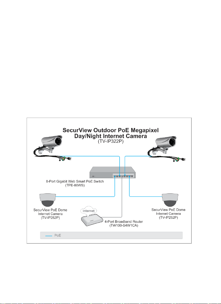
2.4 Applications of the Camera
The camera can be applied in multiple applications, including:
Monitor local and remote places and objects via Internet or
Intranet.
Capture still images and video clips remotely.
Upload images or send email messages with the still images
attached.
The following diagram explains one of the typical applications for your
camera and provides a basic example for installing the camera.
NOTE The camera’s connectors are not waterproof. Please have the
connectors protected by waterproof housing.
Page 18
- 17 -
CHAPTER 3
ACCESSING THE CAMERA
3.1 Using IP Setup
The camera comes with a conveniently utility, IP Setup, which is included
in the Installation CD-ROM, allowing you to search the camera on your
network easily.
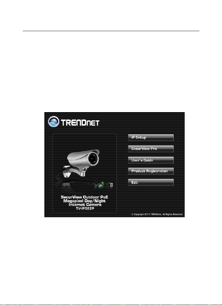
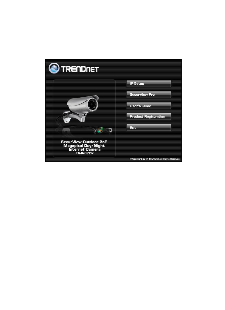
1. Insert the Installation CD-ROM into your computer’s CD-ROM drive
to initiate the Auto-Run program.
Page 19

- 18 -
2. Click the IP Setup from the Auto-Run menu screen. Then IP Setup
Wizard will appear. Click “Next” when the Welcome to the IPSetup
Setup Wizard appears.
3. Click “Browse” to choose the desired destination location. By
default, the destination location is C:\Program
Files\TRENDnet\IPSetup. Then Click “Next”.
Page 20

- 19 -
4. Click “Next” to confirm the IPSetup software to be installed to the
computer.
5. When the Installation Complete window appears, click “Finish”.
Page 21

- 20 -
6. After installing the IPSetup utility, the application is automatically
Camera Display Area
installed to your computer, and creates a folder in “Start
\Program\TRENDnet\IPSetup”.
7. Click Start > Programs > TRENDnet > IPSetup, and then click IPSetup
8. The IPSetup window will appear. It will search the Camera within
the same network.
Page 22
- 21 -
- Camera Display Area: It shows the connected camera(s) within the
same network. By default, the IP setting on the Camera is set up
DHCP. If you have DHCP server, the camera will automatic get the IP
address from DHCP server. If you do not have DHCP server on your
network, it will show the default IP as 192.168.10.30.
Double click the IP address; it will link to Camera’s Web
Configuration page.
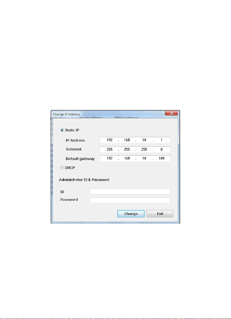
- Change IP: Click this button to bring up the following window. It
allows you to change the IP Address. You can select either Static IP
or click DHCP. Then, enter the Administrator ID & password. By
default ID/password is: admin. When complete, click “Change”.
- Search: Click this button to search the connected camera
within the network.
- Exit: Click this button to exit the program.
Page 23
- 22 -
3.2 Accessing to the Camera
By default, the IP setting on the camera is set to DHCP. It is recommend
to use IPSetup to find the camera’s IP address. Once you find the IP
address of the camera, click Link to access the camera’s web page.
TIP If the camera cannot get the IP address from DHCP server, you can
access the camera by manually entering the default IP address:
192.168.10.30
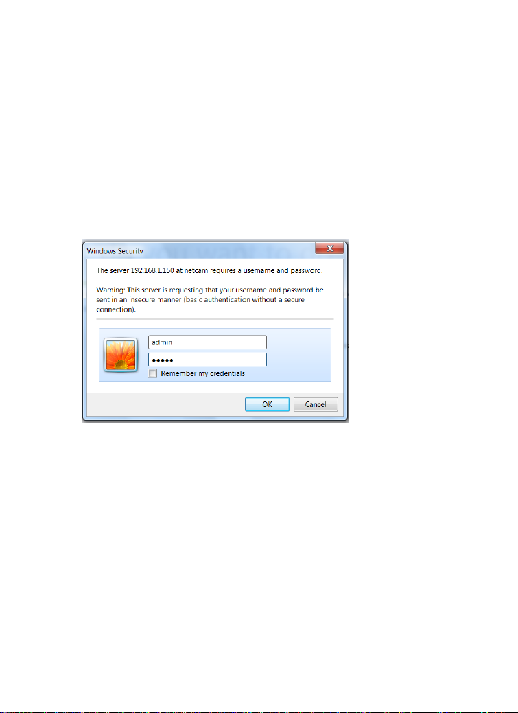
When the login window appears, enter the default User name (admin)
and password (admin) and press OK to access to the main screen of the
camera’s Web Configuration.
NOTE If you are the first time to access the camera, you will be asked to install
a new plug-in for the camera. Permission request depends on the
Internet security settings of your computer. Click Yes to proceed.
Page 24

- 23 -
The Main screen will appear as below:
The Main screen of the Web Configuration provides you with the useful
information and functions, including:
Live View/Setup Switch:
Click the button to configure the camera. For
details, see Chapter 4.
Click the button to return to the Main screen
to view the live view image.
Compression Buttons: Select to transmit and record the video using
H.264, MPEG4 or MJPEG compression.
Function Buttons: Use these buttons to control the audio, video,
and trigger functions.
Manual Record allows you to record and save a video clip.
Page 25

- 24 -
Snapshot allows you to capture and save a still image.
Browse allows you to assign the destination folder to store the
video clips and still images.
Talk allows you to speak out through the camera. Please note
only one user is allowed to use this function at a time.
Listen allows you to receive the on-site sound and voice from
the camera.
Trigger Out allows you to trigger on/off the GPIO output
manually.
Multicast allows you to change the camera’s transmission type
between multicast/unicast.
Live View Image: Displays the real-time video image of the
connected camera. The compression mode is displayed above the
Live View image.
Zoom Buttons: Click the zoom buttons to zoom in/out the live view
image.
Camera Information – Display the camera’s location and the current
date & time. The information can be modified in the Web
Configuration.
NOTE If your computer use Microsoft® Windows® 7/Vista platform, you may
not find the recorded files that are saved by Snapshot or Manual
Record. You need to disable the protected mode of Security in the IE
Browser through the following steps:
Please follow the below Steps:
1. Open IE Browser
2. Select ToolsInternet Options
3. Select Security
4. Uncheck the ”Enable Protected Mode” then press OK
Page 26

- 25 -
3.3 Configuring the IP Address of the Computer
If you are failed to access to the camera, please check the IP address of
your computer. When you connect the camera to your computer directly
to proceed with configuration of the camera, you need to set up the IP
addresses to be in the same segment for the two devices to
communicate.
1. On your computer, click Start > Control Panel to open the Control
Panel window.
2. Double-click Network Connection to open the Network Connection
window.
3. Right-click Local Area Connection and then click Properties from the
shortcut menu.
4. When the Local Area Connection Properties window appears, select
the General tab.
5. Select Internet Protocol [TCP/IP] and then click Properties to bring
up the Internet Protocol [TCP/IP] Properties window.
6. To configure a fixed IP address that is within the segment of the
camera, select the Use the following IP address option. Then, enter
an IP address into the empty field. The suggested IP address is
192.168.10.x (x is 1~254 except 30), and the suggested Subnet mask
is 255.255.255.0.
7. When you are finished, click OK.
Page 27
- 26 -
CHAPTER 4
CONFIGURING THE CAMERA
4.1 Using the Web Configuration
You can access and manage the camera through the Web browser and
the provided software application UltraView Pro. This chapter describes
the Web Configuration, and guides you through the configuration of the
camera by using the Web browser.
To configure the camera, click on the Main screen of
Web Configuration. The Web Configuration will start from the Basic page.
The Web Configuration contains the settings that are required for the
camera in the left menu bar, including Smart Wizard, Basic, Network,
Video/Audio, Event Server, Motion detect, Event Config, Tools, RS-485,
SD Card, and Information.
Page 28

- 27 -
4.2 Using Smart Wizard
The camera’s Smart Wizard lets you configure your camera easily and
quickly. The wizard will guide you through the necessary settings with
detailed instructions on each step.
To start the wizard, click Smart Wizard in the left menu bar.
Step 1. Camera Settings
By default, the camera name is set as model number. Change the name
if necessary. Enter the location and administrator password twice.
Page 29

- 28 -
Step 2. IP Settings
Setup the IP setting, DHCP, Static IP or PPPoE.
Step 3. Email Settings
Enter the mail server information. If you are using a free mails server,
select the SSL and/or STARTTLS according to the mail server requirement.
Page 30
- 29 -
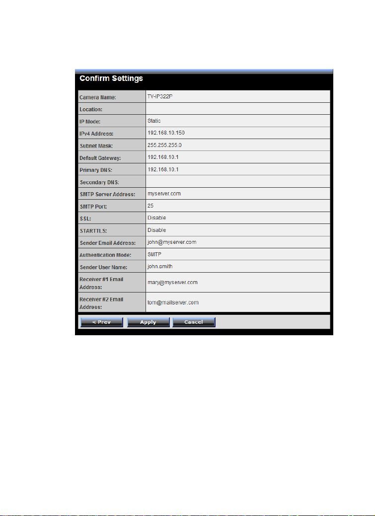
Step 4. Confirm Settings
Click Apply to finish the setting or click Prev to change the previous
setting or click Cancel to disregard all setting.
Page 31

- 30 -
4.3 Basic Setup
The Basic menu contains three sub-menus that provide the system
settings for the camera, such as the Camera Name, Location, Date &
Time, and User management.
Page 32

- 31 -
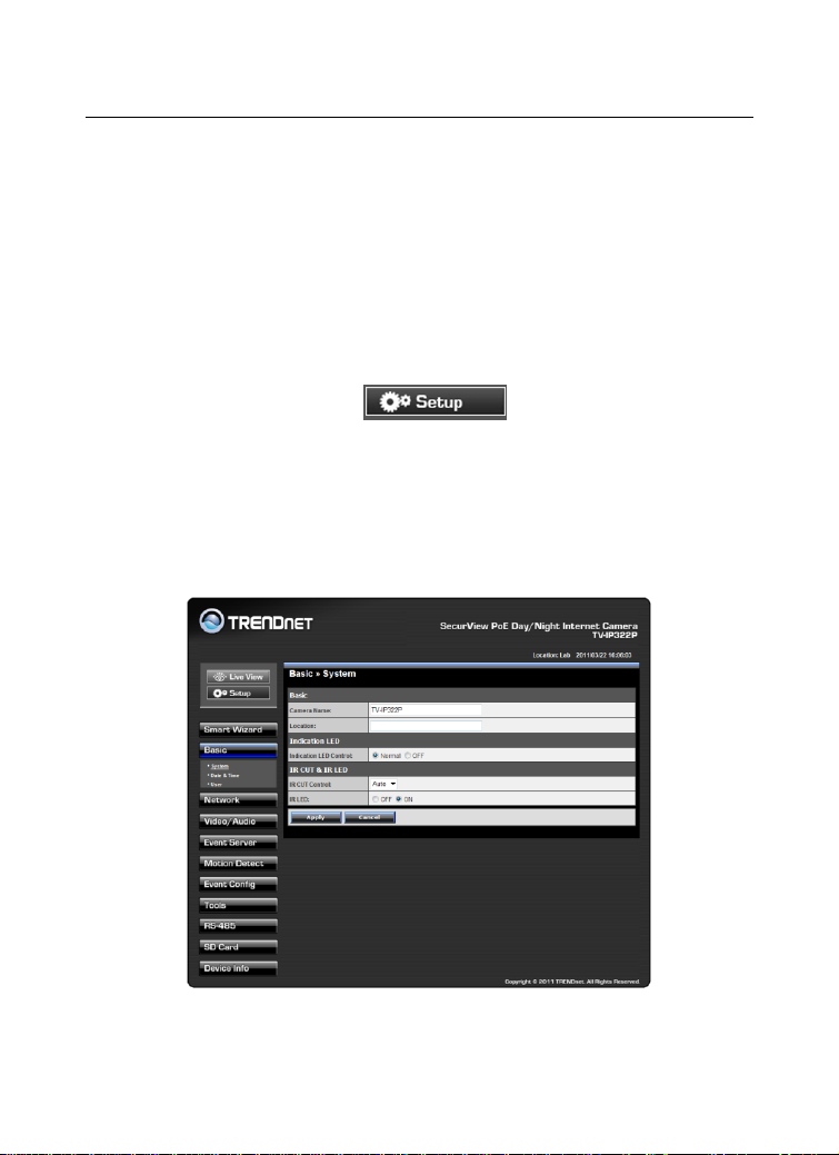
4.3.1 Basic >> System
Basic: This item allows you to assign the camera name and
location.
Camera Name: Enter a descriptive name for the camera, which
will help you to identify the camera when you have multiple
cameras on your network. By default, the camera name is set as
the model number.
Location: Enter a name where the camera is located
Indication LED: This item allows you to set the LED illumination as
desired. The available options include: Normal and OFF.
IR CUT & IR LED: The camera features ICR function (IR CUT Filter)
and IR LED, allowing you to capture clear image when
environment light changed.
IR CUT Control: Set the ICR function (IR CUT filter) for the
camera: Auto mode or Schedule mode.
In Auto mode, the lens filter will be switched automatically to
capture black and white image when the change of
environment light is detected by the camera’s light sensor.
IR LED: Enable or disable the camera’s IR LED manually by
selecting ON or OFF.
Page 33

- 32 -
4.3.2 Basic >> Date & Time
Date and Time: Enter the correct date and time for the camera.
TimeZone: Select the proper time zone from the pull-down
menu.
Synchronize with PC: Select this option and click Apply. The
date & time settings of the camera will be synchronized with
the connected computer.
Synchronize with NTP Server: Select this option and enter the
NTP Server IP address, then click Apply. The date/time will be
synchronized from the NTP Server. By default, the update
interval is set to 6 hours.
Manual: Select this option to set the date and time manually.
When done, click Apply.
Page 34

- 33 -
4.3.3 Basic >> User
Administrator: To prevent unauthorized access to the camera’s
Web Configuration, you are strongly recommend to change the
default administrator password. Type the administrator password
twice to set and confirm the password.
General User
User Name: Enter the user’s name you want to add to use the
camera.
Password: Enter the password for the new user.
UserList: Display the existing users of the camera. To delete a
user, select the one you want to delete and click Delete.
When you are finished, click Add/Modify to add the new user to
the camera. To modify the user’s information, select the one you
want to modify from UserList and click Add/Modify.
Page 35

- 34 -
Guest
User Name: Enter the guest’s name you want to add to use the
camera.
Password: Enter the password for the new guest.
UserList: Display the existing guests of the camera. To delete a user,
select the one you want to delete and click Delete.
NOTE The “General User” can access the camera and control the Function
buttons of the camera’s Web Configuration; the “Guest’ can only view
the live view image from the Main screen of the Web Configuration
while accessing the camera. Only the “Administrator” is allowed to
configure the camera through the Web Configuration. The maximum
12 user accounts.
Direct Video Stream Authentication:
To steam the video directly without going through the configuration
page, you can access it via Internet.
Enable: User needs to enter user name and password to stream
the camera.
Disable: User can stream the camera without entering the user
name and password.
Examples of the direct link to video:
H.264 Mode
http://camera_ip_address:port number/h264view.htm
MPEG4 Mode
http://camera_ip_address:port number/mpgview.htm
MJPEG Mode
http://camera_ip_address:port number/jpgview.htm
NOTE This feature is enabled by default, and for security reason, it is
recommended to have the feature enabled at all time.
Page 36

- 35 -
4.4 Network Settings
The Network menu contains two sub-menus that provide the network
settings for the camera, such as the IP Setting, DDNS Setting, and IP Filter.
4.4.1 Network >> Network
IP Setting: This item allows you to select the IP address mode and
set up the related configuration. The default setting is DHCP mode
enabled.
DHCP: Select this option when your network uses the DHCP
server. When the camera starts up, it will be assigned an IP
address from the DHCP server automatically.
Page 37

- 36 -
Static IP: Select this option to assign the IP address for the
IP
Enter the IP address of the camera. The default
setting is 192.168.10.30.
Subnet Mask
Enter the Subnet Mask of the camera. The
default setting is 255.255.255.0.
Default
Gateway
Enter the Default Gateway of the camera. The
default setting is 192.168.10.1.
Primary/
Secondary DNS
DNS (Domain Name System) translates domain
names into IP addresses. Enter the Primary DNS
and Secondary DNS that are provided by ISP.
camera directly. You can use IPFinder to obtain the related
setting values.
PPPoE: Select this option when you use a direct connection via
the ADSL modem. You should have a PPPoE account from your
Internet service provider. Enter the User Name and Password.
The camera will get an IP address from the ISP as starting up.
NOTE Once the camera get an IP address from the ISP as starting up, it
automatically sends a notification email to you. Therefore, when you
select PPPoE as your connecting type, you have to set up the email or
DDNS configuration in advance.
DDNS Setting: With the Dynamic DNS feature, you can assign a
fixed host and domain name to a dynamic Internet IP address. To
set up the DDNS:
1. Select the Enable option to enable this feature.
2. Select the Provider from the pull-down list.
3. Enter the required information in the Host Name, User
Name, and Password boxes.
NOTE You have to sign up for DDNS service with the service provider before
configuring this feature. Please refer to Chapter 6 for detail
information.
UPnP: The camera supports UPnP (Universal Plug and Play), which
is a set of computer network protocols that enable the device-to-
Page 38

- 37 -
device interoperability. In addition, it supports port auto mapping
function so that you can access the camera if it is behind an NAT
router or firewall. Select the Enable option to enable this feature.
Ports Number
HTTP Port: The default HTTP port is 80.
NOTE If the camera is behind an NAT router of firewall, the suggested port
to be used is from 1024 to 65535.
4.4.2 Network >> Network >> Advanced
HTTPS
Enable: Select this option to enable HTTPS, which is a secure
protocol to provide authenticated and encrypted
communication within your network.
HTTPS Port: Assign a HTTPS port in the text box. The default
HTTPS port is 443.
Page 39

- 38 -
Bonjour: The devices with Bonjour will automatically broadcast
Group IP
Assign a category of IP addresses to receive the
information from the camera.
H.264 Port
Assign a multicast port for H.264 in the text box. The
default port is 1234.
MPEG4 Port
Assign a multicast port for MPEG4 in the text box. The
default port is 1236.
Audio Port
Assign a multicast port for audio in the text box. The
default port is 1238.
TTL
Set the TTL value from 1 to 255, which is used to
modify the time to live field in the IP header.
their own services and listen for services being offered for the use
of others. If your browser with Bonjour, you can find the camera
on your local network without knowing its IP address.
The Apple Safari is already with Bonjour. You can download the
complete Bonjour for Internet Explorer browser from Apple's web
site by visiting http://www.apple.com/bonjour/.
RTSP
RTSP Streaming: Selection the Authentication as Disable or
Enable to configure the transmission of streaming data within
the network. The default RTSP Port (Real Time Streaming
Protocol) is 554.
Multicast settings: Configure the following settings so that you
can deliver information from your camera to a set of receivers.
QoS
Live Video DSCP: Assign the DSCP (DiffServ Code Point) of the
stream video from the camera.
Live Audio DSCP: Assign the DSCP (DiffServ Code Point) of the
stream audio from the camera.
Page 40

- 39 -
4.4.3 Network >> IP Filter
The IP Filter setting allows the administrator of the camera to limit the
users within a certain range of IP addresses to access the camera.
To disable this feature, select the Disable option; otherwise, select the
Accept option to assign the range of IP addresses that are allowed to
access the camera, or select the Deny option to assign the range of IP
addresses that are blocked to access the camera.
Disable: Select this option to disable the IP Filter function of the
camera.
Accept
IPv4: Assign a range of IP addresses that are allowed to access
the camera by entering the Start IP address and End IP address
options. When you are finished, click Add to save the range
setting. You can repeat the action to assign multiple ranges for
the camera.
For example, when you enter 192.168.10.50 in Start IP Address
and 192.168.10.80 in End IP Address, the user whose IP address
Page 41

- 40 -
Deny
located within 192.168.10.50 ~ 192.168.10.80 will not be
allowed to access the camera.
IPv6: Enter the IP Address that is allowed to access the camera.
IPv4: Assign a range of IP addresses that are blocked to access
the camera by entering the Start IP address and End IP address
options. When you are finished, click Add to save the range
setting. You can repeat the action to assign multiple ranges for
the camera.
For example, when you enter 192.168.10.50 in Start IP Address
and 192.168.10.80 in End IP Address, the user whose IP address
located within 192.168.10.50 ~ 192.168.10.80 will not be
allowed to access the camera.
IPv6: Enter the IP Address that is not allowed to access the
camera.
Page 42
- 41 -
4.5 Setting up Video & Audio
The Video & Audio menu contains four sub-menus that provide the video
and audio settings for the camera.
Page 43

- 42 -
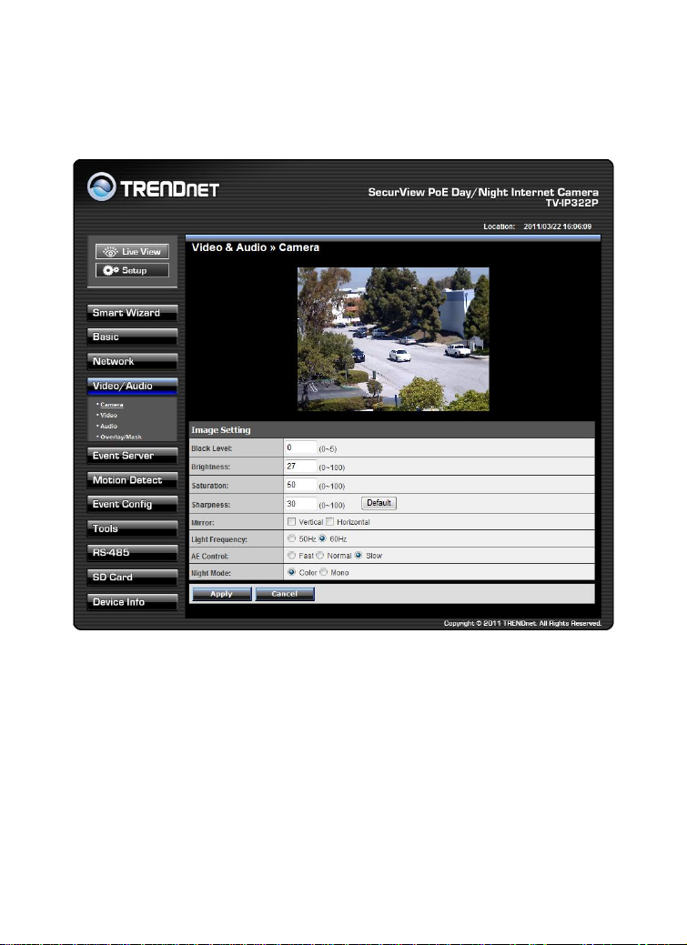
4.5.1 Video & Audio >> Camera
Mode
Frequency
AE Control (Day Time)
min. shutter speed
AE Control (Night Time)
min. shutter speed
Fast
Normal
Slow
Fast
Normal
Slow
VGA
60Hz
1/120s
1/60s
1/30s
1/120s
1/60s
1/30s
50Hz
1/100s
1/50s
1/25s
1/100s
1/50s
1/25s
SXGA
60Hz
1/120s
1/60s
1/15s
1/120s
1/60s
1/15s
50Hz
1/100s
1/50s
1/12.5s
1/100s
1/50s
1/12.5s
Image Setting
Black Level: Adjust the brightness level from 0 ~ 5.
Brightness: Adjust the brightness level from 0 ~ 100.
Saturation: Adjust the colors level from 0 ~ 100.
Sharpness: Adjust the sharpness level from 0 ~ 100.
TIP Click Default to restore the default settings of the three options above.
Mirror: Select Vertical to mirror the image vertically, or select
Horizontal to mirror the image horizontally.
Light Frequency: Select the proper frequency according to the
camera’s location to reduce the noise: 50Hz or 60Hz.
AE Control: Select AE (Auto Exposure) speed as Fast, Normal or
Slow.
Night Mode: Select to capture Color or Mono image when in
dark environment.
Page 44
- 43 -
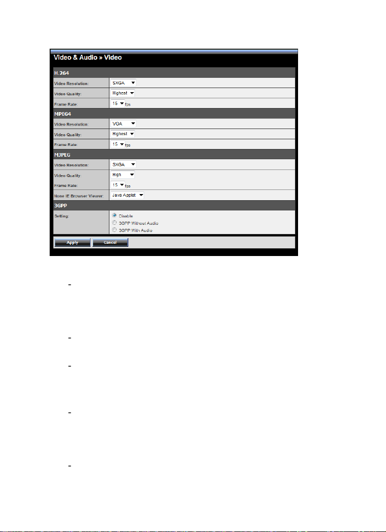
4.5.2 Video & Audio >> Video
H.264
Video Resolution: Select the desired video resolution from the
four formats: SXGA, VGA, QVGA and QQVGA. The higher
setting (VGA) obtains better video quality while it uses more
resource within your network.
Video Quality: Select the desired image quality from five levels:
Lowest, Low, Medium, High, and Highest.
Frame Rate: Select Auto or a proper setting depending on your
network status.
MPEG4
Video Resolution: Select the desired video resolution from the
three formats: VGA, QVGA and QQVGA. The higher setting
(VGA) obtains better video quality while it uses more resource
within your network.
Video Quality: Select the desired image quality from five levels:
Lowest, Low, Medium, High, and Highest.
Page 45

- 44 -
Frame Rate: Select Auto or a proper setting depending on your
network status.
MJPEG
Video Resolution: Select the desired video resolution from the
four formats: SXGA, VGA, QVGA and QQVGA. The higher
setting (VGA) obtains better video quality while it uses more
resource within your network.
Video Quality: Select the desired image quality from five levels:
Lowest, Low, Medium, High, and Highest.
Frame Rate: Select Auto or a proper setting depending on your
network status.
NOTE The camera supports H.264, MPEG4 and MJPEG compression.
Please note that that MJPEG mode captures the images in JPEG
format, which requires higher bandwidth to view smooth video.
You can control the bandwidth of each connection well through
the setting options above. For the bandwidth information, refer
to the Appendix, Bandwidth Reference Guide.
3GPP: The camera supports 3GPP specification. Select the Disable
option to disable this feature. Otherwise, select 3GPP Without
Audio or 3GPP With Audio to transfer the video clips without or
with audio.
If you use a mobile phone that supports 3GPP, you can also view
the real-time streaming image captured by the camera on your
phone (with the default player on the phone) by entering the
RTSP link: rtsp://(IP address of the camera)/3gp.
NOTE Your mobile phone and the service provider must support 3GPP
function. Please contact your service provider when you are
failed to use this service.
Page 46

- 45 -
4.5.3 Video & Audio >> Audio
Camera Microphone In: Select the Enable option to enable the
camera’s audio function, so that you can receive the on-site sound
and voice from the camera.
Camera Speaker Out: Select the Enable option to enable the
camera’s external speaker function, so that the connected
speaker can play the sound and voice through the camera.
You can set the speaker’s volume by entering the proper value in
the Volume option. The default setting is 90.
Page 47

- 46 -
4.5.4 Video & Audio >> Overlay / Mask
This sub-menu is used to set the image overlay and mask feature of the
camera.
Image Overlay: This item allows you to set the image overlay.
In the Image File option, click Browse to select the image file from
your computer, and then click Upload. You can click Preview to
check the image size and adjust the image position before clicking
Upload. The preview image area is displayed with red dotted line.
If you want to remove the preview image before uploading, click
Delete.
Since you click Upload, the preview image area is displayed with
white dotted line. Click Enable and set the transparency setting by
whether selecting the Transparent option or not.
When done, click Apply. You can see the image overlay on the live
view image when you click Live View.
Page 48

- 47 -
NOTE The width and height of the input overlay graphic should be
multiple of 4 at a maximum size of 43690 pixels, and in JPG or
BMP (24-bit RGB) format.
Privacy Mask: This item allows you to configure up to two mask
areas.
Select the area 1 or 2 from the Window pull-down list, and then
click Enable. You can change the size and position of the area by
holding and dragging the mouse.
You can also change the color of the mask area by clicking the
Color box and then selecting the color you want.
When done, click Apply. You can see the mask area(s) on the live
view image when you click Live View.
4.5.6 Video & Audio >> Overlay / Mask >> Text Overlay
This page is used to set the text overlay feature of the camera, including
the following three options: date & time, heading text, and background
transparency setting.
Include Date & Time: Select this option to display the date & time
information on the live view image.
Include Text: Select this option and enter your heading text in the
box to display the text information on the live view image.
Enable Opaque: Select this option to display the overlay text with
a background color.
Page 49

- 48 -
For example, when you select the Include Date & Time and Include Text
options and click Apply, you can see the related information displayed
on the live view image when you click the button.
Page 50

- 49 -
4.6 Event Server Configuration
The Event Server menu contains four sub-menus that allow you to
upload images to FTP, send emails that include still images, and store the
images to a NAS system.
When you complete the required settings for HTTP, FTP, Email, or
Network Storage, click Test to test the related configuration is correct or
not. Once the camera connects to the server successfully, click Apply.
Page 51

- 50 -
4.6.1 Event Server Setting >> HTTP
HTTP Notify For Motion Trigger
Send the query parameter via an HTTP notification when an event is
triggered.
Host: Enter the IP of the HTTP server
Port: Enter the Port number of the HTTP server
User Name: Enter the username of the HTTP server
Password: Enter the password of the HTTP server
Query: Enter the query parameter for the request if necessary
Page 52

- 51 -
Example:
Host: 192.168.10.1
Port: 80
Query: xxx.cgi?name1=value1&name2=value2
Ex: cgi/event.cgi?status=#s&time=#t&model=modelname
Result:
http://192.168.10.1:80/cgi/event.cgi?status=#s&time=#t&model=
modelname
4.6.2 Event Server Setting >> FTP
FTP
Host Address: Enter the IP address of the target FTP server.
Port Number: Enter the port number used for the FTP server.
User Name: Enter the user name to login into the FTP server.
Password: Enter the password to login into the FTP server.
Directory Path: Enter the destination folder for uploading the
images. For example, test.
Passive Mode: Select the Enable option to enable passive mode.
Page 53

- 52 -
FTP Upload with: Select upload to FTP with one snapshot image
Should be
separate?
What is
STARTTLS?
or a series image in pre-event/post-event time when event
triggered.
NOTE Due to the network environment, the camera may not upload
number of images that you set.
4.6.3 Event Server Setting >> Email
Email
SMTP Server Address: Enter the mail server address. For
example, mymail.com. If you are using a free mail service (e.g.
Google Gmail®, Yahoo®, Hotmail®), please enter the SMTP
server address from the service provider.
Sender Email Address: Enter the email address of the user who
will send the email. For example, John@mymail.com.
Page 54

- 53 -
SMTP Port: Assign the SMTP port in the text box. The default
SMTP port is 25. If the mail server requires an encrypted
connection, you should check the SSL option.
SSL / STARTTLS: Most free email services require an encrypted
connection. If you are using a free email service, please check
the mail server requirement and select the options that apply to
the server.
Authentication Mode: Select None or SMTP according to the
mail server configuration.
Sender User Name: Enter the user name to login the mail server.
Sender Password: Enter the password to login the mail server.
Receiver #1 Email Address: Enter the first email address of the
user who will receive the email.
Receiver #2 Email Address: Enter the second email address of
the user who will receive the email.
Send Email With: Select the attachment type that is to be
added to the email.
NOTE Depending on the network environment, your network may not be
able to send all the screen shots that was set to your email account.
Wan IP Change Notify
Select the option to enable the system to notify you when the
WAN IP address changed.
Page 55

- 54 -
4.6.4 Event Server Setting >> Network Storage
Network Storage
Samba Server Address: Enter the IP address of the Network
Storage server.
Share: Assign the folder on the Network Storage server to share
the files to users.
Path: Assign the path for uploading the files on the Network
Storage server. For example, Test.
User Name: Enter the user name to login into the Network
Storage server.
Password: Enter the password to login into the Network
Storage server.
Split By: When the file is too large to upload smoothly, use this
option to split it by selecting File Size or Recording Time.
When Storage Full: Select Stop Recording or Recycle – Delete
Oldest Folder when the storage space on the Network Storage
server is full.
Page 56

- 55 -
Encode Format: Select MPEG4 or H.264 as the encode format
while recording.
File Format: Select MP4 or AVI as the file format while
recording.
NOTE The recorded video files in Network Storage are enclosed by
AVI format without audio.
4.6.5 Event Server Setting >> Instant Message
The camera supports the Jabber IM service, so that you can send an
instant message once you have a Jabber account. For more information
of Jabber, please visit the Jabber Website at:
http://jabber.org/Main_Page. The information show above is using
google talk.
Page 57

- 56 -
Instant Message
Jabber ID: Enter your user ID to login into the Jabber IM service.
Jabber Password: Enter the password to login into the Jabber
IM service.
Manually Specify Server Host/Port: Select the Enable option to
manually configure the Jabber server settings.
Jabber Server Address: Enter the Jabber server address
manually.
Jabber Port: Assign the Jabber port manually in the text box.
Encrypt Connection: Select the Enable option to secure the
connection.
Encrypt Authentication: Select the Enable option to secure the
connection.
Receiver: Enter the receiver’s information.
Message: Enter the message that is to be sent.
Page 58
- 57 -
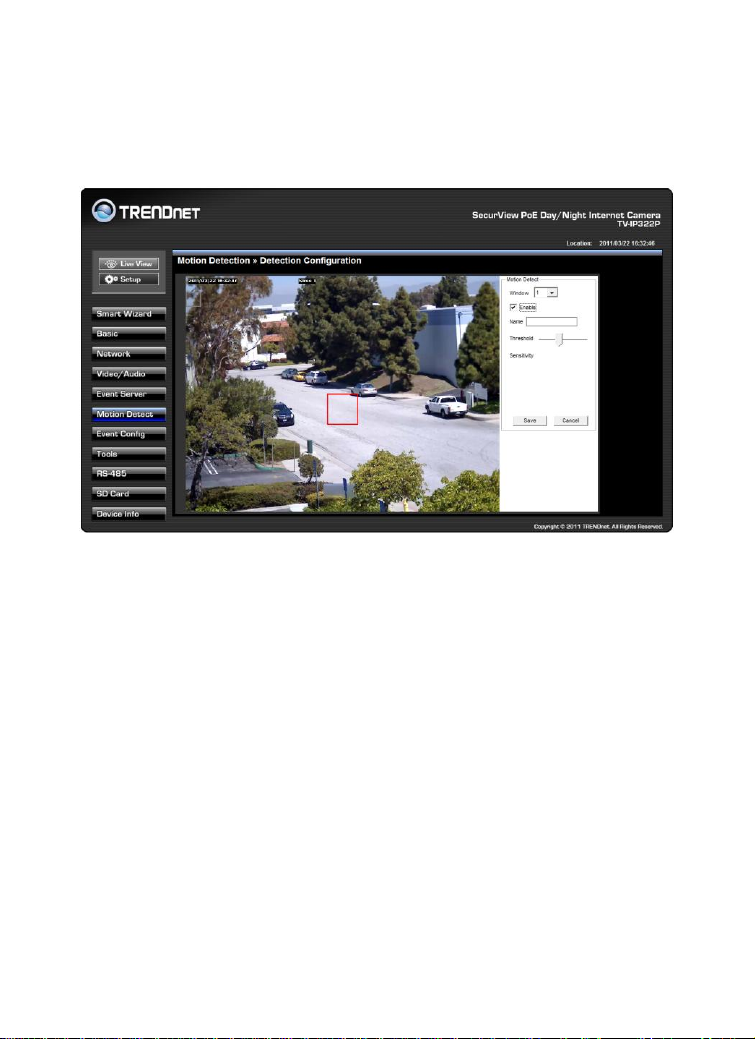
4.7 Motion Detect
The Motion Detect menu contains the command and option that allow
you to enable and set up the motion detection feature of the camera.
The camera provides three detecting areas.
To enable the detecting area, select Window 1/2/3 from the pull-down
list, and then select Enable. When the detecting area is enabled, you can
use the mouse to move the detecting area and change the area coverage.
Name: Assign a name to the detecting area.
Threshold: Move the slide bar to adjust the level for detecting
motion to record video.
NOTE Sliding the Threshold bar to the right will decrease the sensitivity of
motion detection; sliding the Threshold bar to the left will increase
the sensitivity of motion detection.
Page 59

- 58 -
4.8 Event Configuration
The Event Config menu contains five sub-menus that provide the
commands to configure event profiles.
Page 60
- 59 -
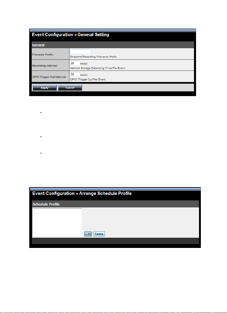
4.8.1 Event Configuration >> General Setting
General
Snapshot/Recording Subfolder: You can assign a descriptive
name for the subfolder to save the captured image/video files.
Otherwise, leave this option blank to use the default setting.
Storage Recording Time Per Event: Limit the recording time
while you are using the Network Storage solution.
GPIO Trigger Out Retention Time Per Event: Limit the retention
time of the GPIO Trigger Out function.
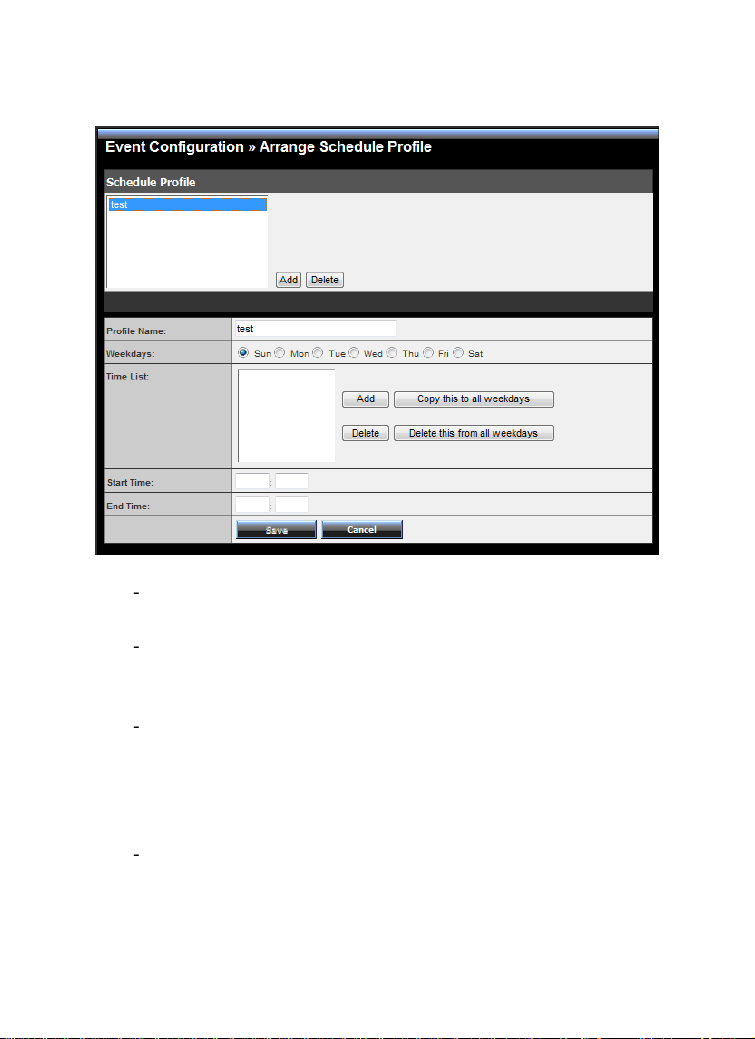
4.8.2 Event Configuration >> Arrange Schedule Profile
Schedule Profile: This sub-menu displays the scheduled profile(s).
To customize the profile, click Add and then enter a descriptive
name for the profile in the prompt dialog window. After entering
the profile name, click OK and the profile is added to the Schedule
Page 61
- 60 -
Profiles list. To delete the profile, select the profile in the list and
click Delete.
Profile Name: Display the profile name that you select in the
Schedule Profiles list.
Weekdays: Select the weekday(s) that you want to separately
assign in the schedule profile. The weekday that has been
assigned will be displayed with green color.
Time List: Display the time period that you have assigned within
the selected weekday. To assign the same time period to every
weekday, click Copy this to all weekdays; click Delete this from
all weekdays to remove the selected time period from every
weekday. Click Delete to remove the selected time period.
Start/End Time: Enter the start and end time and then click Add
to assign a time period within in the selected weekday.
Page 62

- 61 -
4.8.3 Event Configuration >> Motion Detect Trigger
Motion Detect Trigger: Select the Enable option to enable the
trigger function of the camera, so that you can send captured
images within the detecting area to the FTP server, email receiver,
or the Network Storage server. You have to configure
corresponding settings, such as FTP server and email server, to
enable this feature. Please note that you have to configure the
related settings before enabling these features.
Schedule Profile: Select a schedule profile from the pull-down
list.
Action: Set the Trigger Out function or select the destination
that the captured images will be sent to: , or Record to SD Card,
Record to Network Storage, Send Email, FTP Upload, or Instant
Message.
Page 63

- 62 -
4.8.4 Event Configuration >> Schedule Trigger
You can separately configure the schedule for trigger function of the
camera by Email, FTP, or Network Storage. Select the Enable option
on each item, and then select a Schedule Profile from the pull-down
list and set the Interval time.
NOTE If the setting value of the Network Storage Recording Time Per
Event option in General Setting is longer than the Interval time in
Network Storage Schedule, the recorded file will be a continuous
video clip.
For example, if you set the Network Storage Recording Time Per
Event as 10 seconds and the Interval as 5 seconds, recorded file
becomes a non-stop video clip because the camera will record a
10-second video clip every 5 seconds.
Page 64

- 63 -
4.8.5 Event Configuration >> GPIO Trigger
GPIO Trigger: Select the Enable Trigger In 1/2 option to enable
the GPIO trigger function of the camera, so that you can set
Trigger Out function or send captured images within the detecting
area to the SD card, FTP server, email receiver, Network Storage
server, or send an instant message. Event server has to be
configured prior to using the functions.
Schedule Profile: Select a schedule profile from the pull-down
list.
Action: Set the Trigger Out function or select the destination
that the captured images will be sent to: Record to SD Card,
Record to Network Storage, Send Email, FTP Upload, or Instant
Message.
Page 65
- 64 -
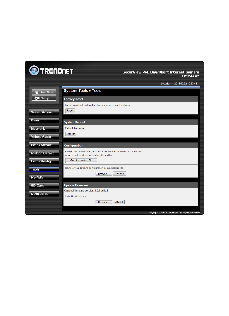
4.9 Tools
The Tools menu provides the commands that allow you to restart or
reset the camera. You can also backup and restore your configuration,
and upgrade the firmware for the camera.
Page 66

- 65 -
Factory Reset: Click Reset to restore all factory default settings for
the camera. You can also do the physical reset by press the reset
button on the camera. Remove the front cover of the camera and
press the reset button as indicates below.
System Reboot: Click Reboot to restart the camera just like
turning the device off and on. The camera configuration will be
retained after rebooting.
Configuration: You can save your camera configuration as a
backup file on your computer. Whenever you want to resume the
original settings, you can restore them by retrieving the backup
file.
Backup: Click Get the backup file to save the current
configuration of the camera.
Restore: Click Browse to locate the backup file and then click
Restore.
Update Firmware: You can upgrade the firmware for your camera
once you obtained a latest version of firmware.
Current Firmware Version: This item displays the current
firmware version.
Select the firmware: Click Browse to locate the backup file and
then click Update.
NOTE Make sure to keep the camera connected to the power source
during the process of upgrading firmware. Otherwise, the
camera might be damaged because of failure of upgrading
firmware.
Page 67

- 66 -
4.10 RS-485
The RS-485 menu provides the control settings for external device
through the I/O port.
Page 68

- 67 -
4.10.1 RS-485 >> RS-485 Setting
Select the Enable option and complete the required configuration to use
the RS-485 function of the device.
Popular Protocol Setting: Select a Protocol (Pelco-D or Pelco-P)
and then select a Camera ID.
Custom Protocol Setting: Select this option to configure the
commands protocol manually. You can click Test to test each
command that you have assigned. In the Name and Command
string boxes, you can customize more buttons for your needs.
Please note that the setting values in the Command string boxes
should be from the connected external device (please refer to the
manual of the connected device).
Page 69

- 68 -
4.10.2 RS-485 >> Patrol
The Patrol function provides the patrol control settings for the
connected camera.
Preset Position
To set the preset position for the connected camera:
1. Use the Navigation buttons to move the camera lens to the
desired position.
2. Select a Position number (Home, 2~32) from the Preset
Position pull-down list.
3. Enter the descriptive name for the location in the text box.
4. Click Apply.
Pan Speed: Adjust the moving speed (1 ~ 10) while
panning the lens.
Tilt Speed: Adjust the moving speed (1 ~ 10) while tilting
the lens.
Page 70

- 69 -
Zoom Speed: Adjust the speed (1 ~ 10) while zooming
the lens.
Focus Speed: Adjust the speed (1 ~ 10) while focusing the
lens.
Zoom In/Zoom Out: Click to zoom in/out the live view
image.
Focus Far/Focus Near: Click to adjust the focus by
far/near.
Patrol Position
This field allows you to set the positions for camera’s patrolling:
1. Select a preset position from the Preset Position pull-down
list, and then click Add to be Patrol Position. The preset
position will be added to the Patrol Path list.
2. From the Patrol Path list, you can change the patrolling order
by selecting a position and clicking Up or Down. You can also
delete a position by clicking Remove.
3. You can change the stay time for each position when the
camera is patrolling. Select a position in the Patrol Path list
and then enter a time setting in the text box below the Stay
Time list. Click Update to save the setting. The Stay Time list
displays the current setting for each position.
4. When done, click Save.
Page 71

- 70 -
4.11 Setting up the SD Card
The SD Card menu allows you to set the SD card function installed in the
camera.
Page 72
- 71 -
4.11.1 SD Card >> SD Card Setting
SD Card Dismount: Click Dismount to safely remove the SD card
that is installed in the camera.
Note: You must disable the event trigger in order to dismount the
SD Card.
SD Card Information: Displays the information of the installed SD
card, including the Total space and Free space.
SD Card Setting
When Storage Full: Select Stop Recording or Recycle – Delete
Oldest Folder when the storage space on the SD card is full.
Encode Format: Select MPEG4 or H.264 as the encode format
while recording.
File Format: Select MP4 or AVI as the file format while
recording.
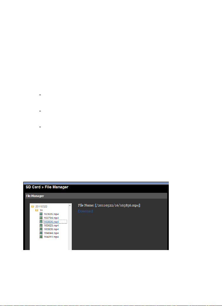
4.11.2 SD Card >> File Manager
The File Manager menu allows you to download files from the SD card.
Select the desire file and click the Download button to download the file.
Page 73

- 72 -
4.12 Information
The Information menu displays the current configuration and events log
of the camera.
Page 74

- 73 -
4.12.1 System Information >> Device Information
Display the Basic, Video & Audio, and Network settings of the camera.
4.12.2 System Information >> Logs
The Logs table displays the events log recorded by the system.
Page 75

- 74 -
CHAPTER 5
SECURVIEW™ PRO SOFTWARE
This chapter describes detailed instructions on using SecurView™ Pro, a
customized software application with a user-friendly interface that
allows you to access your cameras. The Software can monitor and record
up to 36 cameras. It also let you change some basic settings of the
camera, such as schedule profiles and motion detecting areas. The
SecurView™ Pro also supports audio or Pan/Tilt function.
It is recommended to use a high performance computer if you want to
connect multiple cameras simultaneously.
Platform: Microsoft® Windows® 7/Vista/XP
Hard Disk: 80GB or above
Resolution: 1024x768 or above
Hardware Requirement
1 ~ 8 cameras: Intel Core 2 Duo; 2GB RAM
9 ~ 32 cameras: Intel Core 2 Quad; 4GB RAM
* For Windows Vista users: please go to User Accounts and Family
Safety > User Accounts > Turn User Account Control on or off, then
uncheck the checkbox of “Use User Account Control (UAC) to help
protect your computer”. Restart your computer to validate the
setting. For additional information of User Account Control, please go
to
http://www.microsoft.com/windows/products/windowsvista/features/details
/useraccountcontrol.mspx
* For Windows 7 users, please go to Control Panel > User Accounts >
Change User Account Control Setting to lower your notify setting. For
additional information of User Account Control, please go to
http://windows.microsoft.com/en-us/windows7/products/features/useraccount-control
Page 76
- 75 -
5.1 Installation
1. Insert the Installation CD-ROM into your computer’s CD-ROM
drive to initiate the Auto-Run program.
2. Click the SecurView™ Pro from the Auto-Run menu screen.
NOTE: To use SecurView™ Pro, you must have Microsoft .NET
Framework 2.0 installed in the computer. The setup wizard will
detect it and, if the program is not installed yet, it will ask you to
install it during the process of installing SecurView™ Pro.
NOTE: Microsoft® Windows® Installer 3.0 or above is a required
component to install SecurView™ Pro. For more information of
the required component during installation, please visit the
Microsoft support Website.
Page 77

- 76 -
3. Then SecurView™ Pro Setup Wizard will appear. Click “Install”.
4. Wait until the program finish the installation. By default, the
destination location is C:\Program Files\TRENDnet\SecurView
Pro.
Page 78

- 77 -
5. Click “Finish” to finish the installation.
6. After installing the SecurView™ Pro, the application is
automatically installed to your computer, and creates a folder in
“ Start \Program\TRENDnet\SecurView Pro ”.
Page 79

- 78 -
5.2 Using SecurView™ Pro
5.2.1 Launch the Program
To start SecurView™ Pro, click Start > All Programs > TRENDnet
>SecurView™ Pro > SecurView™ Pro. You can also start the program by
double-click the SecurView™ Pro icon on your desktop.
On the login window, enter the User name/Password and click OK to
login. The default User name/Password is admin/admin. If you wish to
save the login information, please select Auto Login.
Page 80

- 79 -
5.2.2 Main Window and Features
When you start and login to SecurView™ Pro, the Main window will
display as below:
The Main window provides you with the information on operating the
system, as well as the control panel such as the Quick Launch buttons,
and so on.
NOTE For best result, it is higher recommended to configure resolution setting
to 1024 x 768 or higher; otherwise, it cannot be displayed on the screen
when launching the program.
Live View Window displays the live video of the connected
camera(s).
Page 81

- 80 -
Quick Launch Buttons are located below the Live View Window,
Button
Function
Logout : To log out the SecurView™ Pro program
Close: To close the SecurView™ Pro program
Restore Recording Type: Restore all recording type to current
camera’s setting
All Continuous Recording: Continuous recording on all
cameras
Stop All Recording: Stop recording on all cameras
View Setting: To configure eMap settings
eMap View: To view current maps
Camera Status: Display cameras status
Playback: Playback recorded files
Schedule: Display Schedule Configuration window
Event Server: Setup a SMTP server
Address Book: Add/Remove email address for event
notification
Event Trigger: Setup event trigger configuration
Device Setting : Set up the camera
Recording Setting: Set up the recording path
Account information: Setup administrator password
Version: Display software version
System Setting: Software settings
providing you with the following quick-launch functions:
Page 82

- 81 -
Camera View Mode buttons in this area allow you to switch the
Buttons
Functions
Display the connected camera(s) in a single camera view
mode.
Display the connected camera(s) in a quad view mode.
Display the connected camera(s) in a 3 x 3 grid view mode.
Display the connected camera(s) in a 13-camera view mode
using a split window. The first camera is displayed as the
major view.
Display the connected camera(s) in a 17-camera view mode
using a split window. The first camera is displayed as the
major view.
Display the connected camera(s) in a N x N grid view mode,
supporting up to 36 cameras.
Display the live view of the selected camera in full screen
mode. Click ESC on the keyboard to return to Main window.
Automatically switch the live view of each connected
cameras in single camera view mode by 30 seconds*. Click
once to start and click again to stop.
* The auto-switch time is set as 30 seconds by default, which
can be changed by clicking the System Setting and
then change the value from the pull-down list of the Auto
Switch time interval option.
camera view mode.
System Information displays the system information, including the
date and time, and the available storage space of the system.
Live View Status provides the status of live view mode, including
Camera List and eMap.
Page 83

- 82 -
Camera List displays the status of the connected cameras. If
Buttons
Functions
Talk On/Off. Click to enable/disable the speaker
function of the connected camera. This option is
available only in single camera view mode.
Listen On/Off. Click to enable/disable the microphone
function of the connected camera. This option is
available only in single camera view mode.
For Pan/Tilt cameras, use this control panel to set the
preset positions (up to 8 positions).
Use Navigation buttons to adjust camera position, and
then select the position number (1~8) from the Set
button.
To move to the preset position, simply select the
position number (1~8) from the Go button.
Navigation Buttons (Left/Right/Up/Down/Home). If the
connected camera has pan/tilt functions, the Navigation
buttons allow you to move the camera lens position.
Clicking the Home (center) button will move the camera
lens to the assigned home position.
/
The Patrol/Stop buttons are used to enable/disable the
patrol function of the camera. Click Patrol to start
patrolling through the preset positions once. Click Stop
to stop patrolling.
multiple cameras are connected, you can switch to the live
view of each camera by simply selecting the camera from
the list.
eMap allows you to select the desired camera to the view
from the map easily. Please note that you have to set up
the eMap for monitoring in advance.
Camera Control Buttons provides the control buttons that allow you
to control the selected camera.
Page 84

- 83 -
5.2.3 Manage the Cameras
Before adding the cameras, please setup the recording setting first.
Configure Recording Settings
1. Click the button and then select Record Setting.
2. Default path is C:\, click Browse and select the desire
directory then click Save to complete the configuration.
To change the time interval for recording, select time from
the pull-down menu.
NOTE: The system will automatically delete the oldest files (10%) when the size
of recorded files is up to 90% of the storage space.
Page 85

- 84 -
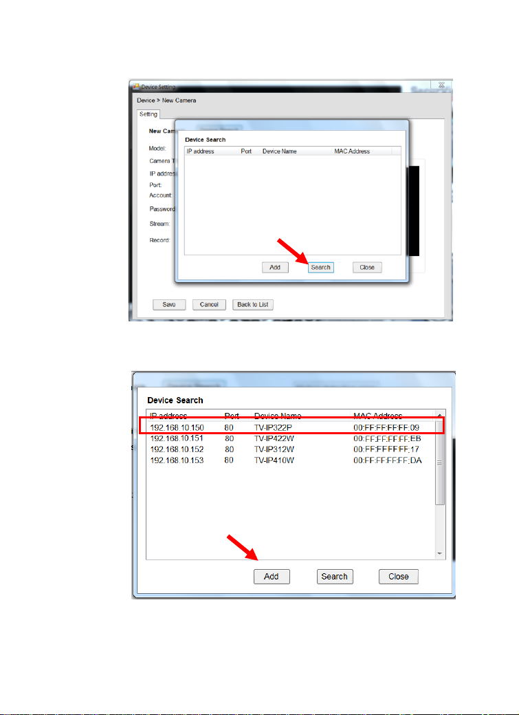
Add a Camera
1. Click the button and select Device Setting to display the
Device Setting window.
2. Click New.
Page 86
- 85 -
3. Click on Search, all cameras that’s connected to your
network would appear.
4. Select the camera you would like to add and then click Add.
Page 87

- 86 -
5. The information of the camera will display on the screen.
It will auto detect the IP address/port number and display
the stream type of the camera. Please type in the correct
user name and password, then select Preview to view live
image.
6. To setup recording style, select Yes on Record option.
These four recording types will appear. Select one of the
recording type, configure it then click Save.
Continuously:
Record the stream video continuously
Schedule:
Page 88

- 87 -
Records stream video by schedule. You can setup the
schedule by click Add Schedule here.
Click on New to create a new schedule and select the time
to record. Click on Save when finish.
Motion:
Record video by Motion Detection. Motion detection
recording required to setup a motion detection area. If you
are adding a new camera, you must preview the camera
first in order to setup the motion detection area.
Page 89

- 88 -
Click on Motion detection area to setup
Enable motion detection windows, set up the senstivity and
click on Save.
Page 90

- 89 -
Motion by Schedule:
same requirement as Motion & Schedule recording.
Digital Input:
Recording triggered when there I/O port is triggered.
After all recording methods are configured, click Save to
apply the settings.
Page 91

- 90 -
7. Camera list will appear with recording type notification.
8. Once you added all the cameras, click the close button “x”
on the Device Setting windows to return to the main
windows. The cameras will display here.
Page 92

- 91 -
NOTE Divx/Xvid codec is required for viewing the image of camera. If the
image cannot be displayed in the Live View/Preview window normally,
click the following path to download and install the required component:
http://download.divx.com/divx/DivXInstaller.exe
Edit / Delete a Camera
1. To edit a camera: From the Device Setting window,
highlight the camera you would like to edit then click on
Modify button.
Page 93

- 92 -
2. To delete a camera: select the desired one and then click
Remove. Click Yes to confirm.
View Camera Image
Since you have added camera(s) to the system, the image of the
selected camera(s) will be displayed on the Live View Window
automatically. You can view a maximum of 36 cameras
simultaneously. Additionally, you can select one-camera or
other view mode to display the video from the Camera View
Mode buttons.
For example, if you use only one camera, select single camera
view mode ( ), and the Live View Window will display the
view as below. You can select the other modes according to
your need.
Page 94

- 93 -
The Information icon ( ) on the top-right corner of the
window provides you with the options to connect/disconnect
the camera, select a camera to be displayed in the window,
capture a still image of the camera live video, or switch to eMap
mode. Click the Information icon to pop up the shortcut menu
and select the desired option.
Page 95

- 94 -
Playback the Recorded Files
1. Click the button to display the Playback window.
2. On the Playback window, select the camera and setup the
begin/end date and begin/end time, then click Search. The
search result will be displayed in the Record File list.
Page 96

- 95 -
3. To playback the video clip, select the desired file and click
Play.
5.2.4 eMap Setup & Camera Status
Manage eMap
Click the button and select View Setting to manage eMap.
eMap refers to the geography and device scope in the
SecurView™ Pro, which visually presents the devices in your
security system. It uses a background of the area (e.g. a picture
or a map) as the interface for monitoring.
Page 97

- 96 -
To add an eMap
1. On the View Setting window, click New.
2. Enter an eMap name.
Page 98

- 97 -
3. Click Browse to select a Picture File from your computer.
Picture will display in the Preview window.
4. Click Save and click OK to apply the settings.
Page 99

- 98 -
5. Click Camera Location to assign the camera location.
6. The following screen appears.
Page 100

- 99 -
7. Select the camera from the list and then click the position
on the map. The camera icon will be displayed on map.
8. Click Save when complete.
 Loading...