


DRAG TIMING SYSTEM
|
|
|
|
OWNER’S MANUAL |
MODEL 6570 |

2 PRECAUTIONS
4TIMING SYSTEM COMPONENTS
5GETTING STARTED
6SYSTEM SETUP
9RACING
10MAINTENANCE
11TROUBLESHOOTING
12SYSTEM PROGRAMMING
14TRAXXAS DRAG RACING SCHOOL
15GLOSSARY
If you need assistance, give us a call at 1-888-TRAXXAS.
We’re here to help you Monday through Friday, 8:30am to 9:00pm central time.
E-mail customer support with your question at support@Traxxas.com.
INTRODUCTION
Thank you for purchasing the Traxxas DTS-1 drag timing system. The Traxxas DTS-1 is designed to operate and run races that are an accurate simulation of NHRA drag racing. We have tried to capture every detail and nuance so that you and your friends can experience the intensity of competition of the real thing. Cutting the best light and achieving the lowest ET requires practice and skill that develops over time. That’s all part of the fun. While you may already be familiar with drag racing, in order to better understand the procedures and operation of the DTS-1, we recommend that you go to Traxxas Drag Racing School on page 14 of this manual. There you will find a glossary of terms and we’ll take you through the steps of an actual race. From there, go through the following instructions to get your system set up and Ready-To-Race.®
Precautions
Warning: The DTS-1 uses visible lasers for the beams. Places where laser light is emitted are marked by yellow warning stickers on the consoles. To avoid the potential for injury, do not look into the beam windows on the consoles. Make sure the on/off switch is in the off position before installing batteries. Make sure the consoles are flat on the ground before turning the power on. Do not direct the lasers at persons or animals. Children 14 years and under require adult supervision. Read the warnings and precautions before proceeding or using your DTS-1.
•The DTS-1 timing system is not intended for use on public roads or congested areas where its operation can conflict with or disrupt pedestrian or vehicular traffic.
•Never, under any circumstances, operate R/C models in crowds of people. R/C models can cause injury if allowed to collide with anyone.
•Do not operate R/C models at night, or anytime your line of sight to the models may be obstructed or impaired in any way.
•Because R/C models are controlled by radio, they are subject to radio interference from many sources that are beyond your control.
•Since radio interference can cause momentary losses of radio control, always allow a safety margin in all directions around the model in order to prevent collisions.
•Most importantly, use good common sense at all times.
2 • DTS-1 TIMING SYSTEM
INTRODUCTION
Caution: Use of controls or adjustments or performance of procedures other than those specified herein may result in hazardous radiation exposure.
Warning: The Starting and Finish Line Consoles emit lasers from both sides of the consoles. Do not power-on the consoles unless they are flat on the ground. Do not pick up, transport, or store the consoles while they are powered on. The consoles must be powered off before handling, carrying, transporting, or storing.
Warning: Laser Light - Avoid Direct Eye Exposure.
The DTS-1 Timing System uses visible lasers. Due to the potential for injury, do not point the lasers at persons or animals.
Laser Specifications
Product: Laser Diode
Beam Power Level: Po: ≤5mW Beam Diameter: <3mm
Beam Divergence: -5.6 mRad (Start) -1.5 mRad (Finish)
Emissions: CW
Rating: 6.0V DC
Class: Class 3R Laser
Wave Length: 650nm
LASER LIGHT
AVOID DIRECT EYE EXPOSURE CLASS 3R LASER PRODUCT 635-655nm <5mW CW
EN/IEC 60825-1 2007
Check for Firmware Updates when Using Traxxas Link
The DTS-1 is ready to go right out of the box for stand-alone use. If you wish to connect the DTS-1 to your Traxxas Link application (using a TQi transmitter with Docking Base and an iPhone or iTouch), then check for the latest firmware updates to ensure optimum compatibility and performance with the Traxxas Link application.
Do this before taking the unit out to the running location. Updating the firmware can take 15-20 minutes, so plan ahead. Refer to the instructions in the Traxxas Link app. The application will take you step by step through the firmware updating process. The DTS-1 is ready to go right out of the box for stand-alone use and does
NOT require a firmware update for use without the Traxxas Link application.
Traxxas
1100 Klein Road
Plano, Texas 75074
Phone: 972-265-8000
Toll-free 1-888-TRAXXAS
Internet Traxxas.com
E-mail: support@Traxxas.com
Entire contents ©2012 Traxxas. No part of this manual may be reproduced or distributed in print or electronic media without the express written permission of Traxxas. Other brand names and marks are the property of their respective holders and are used only for purposes of identification. No part of this manual may be reproduced or distributed in print or electronic media without the express written permission of Traxxas. Specifications are subject to change without notice.
DTS-1 TIMING SYSTEM • 3
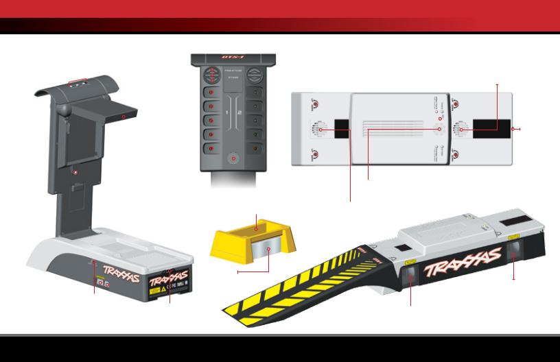
TIMING SYSTEM COMPONENTS
DTS-1 Starting Line Console and Tree
Sun Shade 

Programming |
Pre-Stage LED |
|
|
|
|
|
|
|
||||||||||||||
Buttons |
|
|
|
|
|
|
|
|
|
|
|
|
|
|
|
|
||||||
|
|
|
|
|
|
|
|
|
|
Stage LEDs |
|
|
|
|
|
|||||||
|
|
|
|
|
|
|
|
|
|
Yellow LEDs |
|
|
|
|
|
|
||||||
|
|
|
|
|
|
|
|
|
|
|
|
|
|
|
||||||||
|
|
|
|
|
|
|
|
|
|
|
|
|
|
|
|
|||||||
|
|
|
|
|
|
|
|
|
|
|
|
|
|
|
|
|
|
|
|
|
|
|
|
|
|
|
|
|
|
|
|
|
|
|
|
|
|
|
|
|
|
|
|
|
|
|
|
|
|
|
|
|
|
|
|
|
|
|
|
|
|
|
|
|
|
|
|
|
|
|
|
|
|
|
Flip-Out |
Green LED |
|
|
|
|
|
|
|
|
|
||||||
|
|
|
|
|
|
|
|
|
|
|
|
|
|
|
||||||||
|
|
|
|
|
|
Antenna |
|
|
|
|
|
|
|
|
|
|
|
|
|
|||
|
|
|
|
|
|
|
|
|
|
Red LED |
|
|
|
|
|
|
|
|
|
|
|
|
|
|
|
|
|
|
|
|
|
|
|
|
|
|
|
|
|
|
|
|
|
||
|
|
|
|
|
|
Ambient |
Speaker |
|
|
|
|
|
|
|
|
|
|
|
||||
|
|
|
|
|
|
|
|
|
|
|
|
|
|
|
|
|
|
|||||
|
|
|
|
|
|
|
|
|
|
|
|
|
|
|
|
|
|
|
||||
|
|
|
|
|
|
Light Sensor |
|
|
|
|
|
|
|
|
|
|
|
|
|
|||
Laser Reflector
Pocket for Ballast  (if necessary)
Reflector
Beam Up/Down |
|
|
|
|
|
|
|
|
|
|
||
|
|
|
|
|
|
|
|
|
|
|||
Adjustment |
|
|
|
|
|
|
|
|
|
|
|
|
|
|
|
|
|
|
|
|
|
|
|
|
|
Pre-Stage Beam |
|
|
|
|
|
|
|
|
|
|
||
|
|
|
|
|
|
|
On/Off |
|||||
|
|
|
|
|
|
|
||||||
|
|
|
|
|
|
|
|
|
|
Switch |
||
|
|
|
|
Stage Beam |
||||||||
|
|
|
|
|
|
|
||||||
DTS-1 Finish Line Console
|
|
|
|
|
|
|
|
Finish Beam Up/Down |
|
|||||||||
Speed Trap |
Programming |
Adjustment (Lane 1) |
|
|
Mounting Cover for |
|||||||||||||
|
|
|
|
|
|
|
|
|
|
|||||||||
Beam Up/Down |
Button |
Programming LEDs |
Optional Cooling Fan |
|||||||||||||||
Adjustment (Lane 1) |
|
|
|
|
(Lane 1) |
|
|
|
|
|
|
|
(sold separately) |
|||||
|
|
|
|
|
|
|
|
|
|
|
|
|
|
|
|
|
|
|
|
|
|
|
|
|
|
|
|
|
|
|
|
|
|
|
|
|
|
|
|
|
|
|
|
|
|
|
|
|
|
|
|
|
|
|
|
|
On/Off
Switch
|
|
|
|
|
|
|
|
|
|
|
|
|
|
|
|
|
|
|
|
|
|
|
|
|
|
|
|
|
|
|
|
|
|
Speed Trap |
|
|
|
|
|
|
|
|
|
|
Finish Beam Up/Down |
|||||
|
Speaker |
|||||||||||||||
Beam Up/Down |
|
|
|
|
|
|
|
|
|
Adjustment (Lane 2) |
||||||
Adjustment (Lane 2) |
|
|
|
|
Programming |
|
|
|
|
|
|
|
|
|||
|
|
|
|
|
|
|
|
LEDs (Lane 2) |
||||||||
Mounting Cover for Optional Cooling Fan
(sold separately)
Finish Beam
 Speed Trap Beam
Protective
Ramp
4 • DTS-1 TIMING SYSTEM
GETTING STARTED
Determine Where to Run
You will need a very flat and smooth surface to run the models. Avoid
surfaces that have a large “crown” or dips/gutters to facilitate drainage. |
||||
Find an area that is blocked from access by vehicular and pedestrian |
||||
traffic. A distance of 100-330 |
|
|
|
|
|
Distance equivalent to: |
|||
feet is recommended for |
|
|||
|
1000 Feet |
|
1320 Feet |
|
|
|
|||
scale representations of |
Scale |
|
||
(NHRA Rules) |
|
(Standard 1/4 mile) |
||
drag racing. Remember to |
|
|||
|
|
|
|
|
1/16 |
62.5 feet |
|
82.5 feet |
|
leave adequate room to |
|
|||
|
|
|
|
|
1/10 |
100 feet |
|
132 feet |
|
safely decelerate and stop |
|
|||
your vehicle once you cross |
1/8 |
125 feet |
|
165 feet |
the finish line. |
|
|
|
|
1/4 |
250 feet |
|
330 feet |
|
|
|
|||
|
|
|
|
|
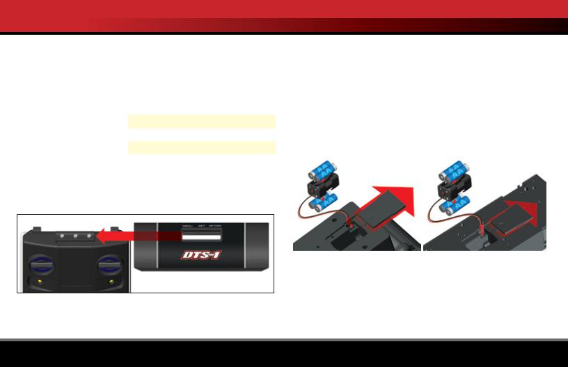
Installing the Sun Shade
Slide the sun shade onto the top of the tree. Install the shade so MENU/ SET/OPTION label reads right-side up when facing the Starting Console.
Battery Installation
The DTS-1 System uses 8 AA batteries (4 in each console). The battery compartments are located on the bottom of each console.
Note: The optional Traxxas rechargeable NiMH battery pack (#3037, sold separately) can be used in place of the AA alkaline batteries.
1.Remove the battery compartment door by sliding the door open.
2.Remove the battery holder. Install 4 fresh batteries in the battery holder. Correct orientation is indicated in the battery holder. Make sure the battery holder is plugged into the console.
3.Reinstall the battery holder. Replace the battery door and snap it closed.
Starting Line Console |
|
Finish Line Console |
Battery Installation |
|
Battery Installation |
|
|
|
DTS-1 TIMING SYSTEM • 5
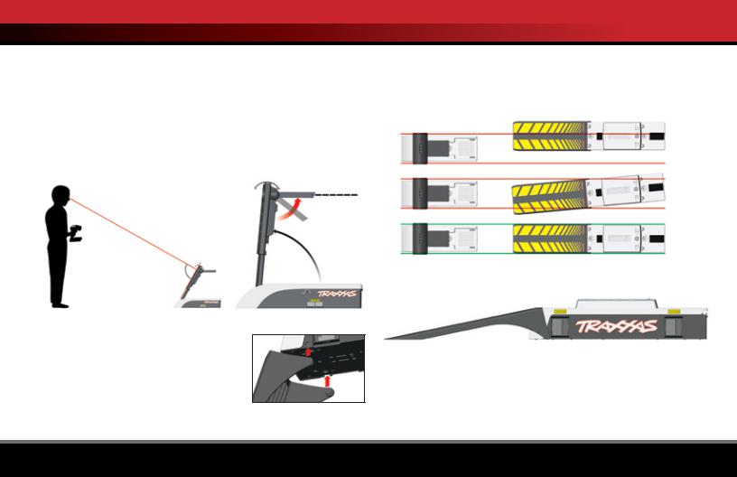
SYSTEM SETUP
Starting Line Console Setup
1Place the DTS-1 Starting Line Console on the starting line. The second beam is the actual start line.
2.The console must sit as flat and secure as possible without rocking on an uneven surface.
3.LED’s produce a directional light beam. Raise the tree and position it so that the LEDs are shining directly at you when you are at your driving position behind the start line.
4.Fold out the antenna so that it points towards the finish line.
Flip antenna out to horizontal
90°
Finish Line Console Setup
1.Install the console ramp by inserting the ramp’s hinge pins into the console as shown and rotating it into proper position. The ramp is there to prevent a vehicle from a direct impact with the Finish Line Console.
2.Use a tape measure or measuring wheel to mark of the track distance you wish to run. See the chart on page 5.
3.Position the Finish Line Console so that the second beam (farthest beam) shines across the finish line. It should sit on level ground as flat and secure as possible without rocking on an uneven surface.
4.For maximum race accuracy, make sure both consoles are directly in line as shown.
8
8
4
5.Make sure to leave adequate room past the finish line for you to safely decelerate and stop your vehicle.
Linking the Starting and Finish Line Consoles
Switch the Starting Line Console and Finish Line Console on. It does not matter which is turned on first. As the components electronically link, the yellow LEDs on the consoles will light in a ‘rotating’ pattern. When the link is complete, the 2 green LEDs on the Starting Line Console will flash
6 • DTS-1 TIMING SYSTEM
 Loading...