

Page 1
CenTraVac
™
Liquid Chillers
Centrifugal Liquid Chillers/
Water-Cooled
170-3500 Tons
50 and 60 Hz
Built For the Industrial and Commercial Markets
CVHE — Three Stage
170
CVHF — Two-Stage CenTraVac
325 1750
LHCV — Module CenTraVac
1300
GPC — Gas Powered CenTraVac Package
170
500
CVHG — Three Stage
450 1300
3500
3500
CTV-PRC007-ENApril 2001
Page 2

World’s Most
Efficient Lowest
What We Mean By Earth•Wise
Breaking the .48 kW/Ton
Efficiency Barrier
The Trane Earth•Wise CenTraVac has a
proven track record as literally the
world’s most efficient, lowest emissions
chiller. In fact, a portion of the product
line is selectable at an unmatched
efficiency level of .48 kW/ton, at standard
ARI rated conditions. This is an efficiency
level of 16 to 25 percent better than
competitive chillers using other
alternative refrigerants, which are
typically in the .56 to .60 kW/ton range.
On a 1000-ton chiller, this efficiency
difference can provide savings of over
$24,000 per year or nearly three quarters
of a million dollars over the life of the
machine . . . typically more than twice
the initial cost of the machine. And, at
part-load conditions, the kW/ton ratings
are even better; a fact that can be seen
by comparing Trane’s ARI certified
applied part load values (NPLV’s) to
those of competitive units.
The development of the .48 kW/ton
chiller also has a positive environmental
impact. Consider this:
If every centrifugal chiller in the world
were able to operate at .48 vs .56 kW/ton,
utility generated greenhouse gas
emissions could be reduced annually by
nearly 17 billion pounds of CO
SO
and NO
2
64 and 27 billion grams, respectively.
This reduction is equivalent to removing
more than two million cars from the
road or to planting nearly 500 million
trees each year.
could be reduced by over
x
while
2
Introduction
Lowest Total Refrigerant
Emissions In The Industry
Furthermore, the Trane “near zero”
emissions Earth
the lowest total refrigerant emissions in
the industry. So low that it’s essentially
a closed system.
The key to the industry’s highest energy
efficiency and lowest leak rate is the
use of a low pressure refrigerant
DuPont calls SUVA-123; a refrigerant
that has the lowest direct-effect global
warming potential and the highest
thermodynamic efficiency of all nonCFC refrigerants; a refrigerant in use in
more new centrifugals today than all
other alternatives combined.
Balancing Our Accountability
for Ozone Depletion, Global
Warming and Energy
Efficiency
Reduced power plant emissions and
the industry’s lowest refrigerant
emission rate put the Trane .48 kW/ton
Wise centrifugal chiller in a class
Earth
•
by itself, from both a business and an
environmental standpoint. The future
lies in the prudent balance that takes
into account the importance of ozone
depletion, global warming and energy
efficiency. A balance that is right for
both business and the environment.
Wise chiller also has
•
Emissions Chiller
Built For The Industrial Market
Direct drive for reliability
•
Multi-stage compressor for efficiency.
•
“Near Zero” refrigerant emission
•
design.
Evaporator and condenser designed to
•
maximize efficiency and reduce
operating costs.
Proven shell and tube design offering a
•
variety of high performance heat
transfer surfaces.
Evaporator, condenser and
•
compressor combinations allow
selection of a chiller that best meets
the system requirements.
Options like heat recovery, free
•
cooling, auxiliary condensers, ice
storage and a unit-mounted starter for
expanded capability and maximum
efficiency.
Complete factory assembly of the
•
CenTraVac
assembly labor and expense.
Machines designed for operating with
•
environmentally acceptable HCFC-123.
Trane patented fixed orifice system for
•
ensuring proper refrigerant flow at all
load conditions. This eliminates the
need for other moving parts such as
float valves, expansion valves.
Low speed direct drive capability offers
•
up to 5 percent more energy efficiency,
at full load, than gear drive chillers.
Also, low speed direct-drive operation
improves reliability and maintenance
costs are also lower.
CenTraVac control panel
•
Adaptive Control
•
Microprocessor based
•
Complete operating status and
•
diagnostics display.
Interfaces with building management
•
system.
High efficiency Purifier™ Purge works
•
as an early warning leak detector that
also takes purge refrigerant emissions
to an industry low.
™
options for reduced jobsite
™
CTV-PRC007-EN©American Standard Inc. 2001
Page 3
Contents
Introduction
Features and Benefits
Components, Standard and Optional Features,
Factory Performance Testing,
Refrigeration Cycle, Control Panel
Unit Options
Unit Mounted Starter, Adaptive Frequency Drives,
Free Cooling
System Options
Auxiliary Condenser, Ice Storage, Heat Recovery,
Chilled Water Resets
Application Considerations
Selection Procedure
Performance Data
Jobsite Connections
2
6
13
21
26
28
30
32
CTV-PRC007-EN
Controls
Weights
Physical Dimensions
Mechanical Specifications
33
39
41
48
3
Page 4

Trane Hermetic
Centrifugal
A Tradition of Innovation
The first Trane centrifugal chiller, the
Turbovac™ was introduced in 1938. The
simple, direct drive, slow speed design
of the Turbovac revolutionized the air
conditioning industry. The chiller was
attractive to customers because its
hermetic design reduced frequent
service requirements.
™
In 1951 the Trane CenTraVac
chiller was introduced. Its unique two
stage compressor with multiple inlet
guide vanes and patented economizer
reduced energy consumption on typical
applications to less than 0.8 kW/ton.
The model PCV CenTraVac chiller that
was introduced in 1966, allowed quality
air conditioning for applications as small
as 120 tons.
In 1982 the CenTraVac chiller solidified
its position as the industry leader by
introducing a three-stage compressor
and a two-stage economizer. As a result,
this chiller was 5 to 20 percent more
efficient than previous designs.
Today’s CenTraVac chiller still relies on
the dependability of the proven direct
drive and exclusive slow speed
operation. Low operating costs and high
reliability continue to be the CenTraVac
chiller hallmark.
When a source of energy other than
electricity is required
The Trane CenTraVac has the standard
option of being coupled to a Waukesha
Enginator to quite simply convert
natural gas to chilled water. With COPs
in the range of 1.5 to 2.2 depending on
options selected, makes this option a
very simple and attractive alternative
when an alternative fuel source is
desired.
centrifugal
Introduction
Trane GPC* Benefits
Combines two industry-recognized
•
and proven products, the Trane
Earth•Wise CenTraVac and Waukesha
Enginator
Ability to do both base and peak
•
shaving
No on-site piping connections
•
Refrigerant leaks minimized
•
No need to remove refrigerant
•
charge from chiller during downtime
Installations more flexible, simpler
•
and cost effective
Ability to place the engine generator
•
set in a location remote of the chiller
Allows for efficient use of plant floor
•
space
Provides flexibility in sound sensitive
•
work areas
*Limited availability for International orders –
Please contact International CenTraVac Marketing
Group.
Unmatched Expertise
The performance and reliability of a
CenTraVac
of experienced field sales engineers with
support from headquarters experts. No
other manufacturer can offer that degree
of support to its customers.
In the design phase, application
engineers can help answer your
questions or solve your problems.
During the selection phase, software
engineers are available to help you
evaluate equipment alternatives. At the
installation stage, field start-up of the
CenTraVac chiller is included in the
purchase price. Trane offers this support
and more when you need it.
Delivery And Design Flexibility
If delivery time is a priority, Trane can
meet your needs with a variety of quick
shipment choices. Most fast track
building schedules can be met with one
of these choices.
Design flexibility means Trane can
custom build a unit to specific job
requirements. Design parameters such
as shell type, compressor, kW/ton,
waterside pressure drop, as well as full
and part load performance can be built
to meet requirements.
™
chiller is backed by a team
Water Chillers
ISO 9001 Certification
ISO 9001 Certification applies to the
Trane La Crosse Business Unit. This
process is based on the La Crosse
Business Unit’s ISO 9001 certified quality
system. This system is documented in
procedures which define how quality
assurance activities are managed,
performed, and continuously monitored.
Included in the system are verification
checkpoints from the time the order is
entered until final shipment. In addition,
product development for the
marketplace is subjected to formal
planning, review and validation. The
system is designed to assure maximum
consistency in meeting customer
requirements.
The Beauty of Simplicity
The reliability of a centrifugal chiller
starts with its basic product design. At
Trane we’ve found that the straightest
path to reliability is simplicity. Years of
research and field testing have honed
the design of the CenTraVac chiller to a
simple, precise solution to a complex
engineering problem.
This simple design provides efficiency
and reliability benefits. The Trane
CenTraVac chiller has only one moving
part — no gear boxes, couplings or extra
shafts. The single rotating shaft is
supported by two aircraft turbine grade/
rated bearings. This direct drive concept
minimizes the chance of failure for
moving parts. It also reduces wear and
drag on parts, resulting in more efficient
operation.
CTV-PRC007-EN4
Page 5
Introduction
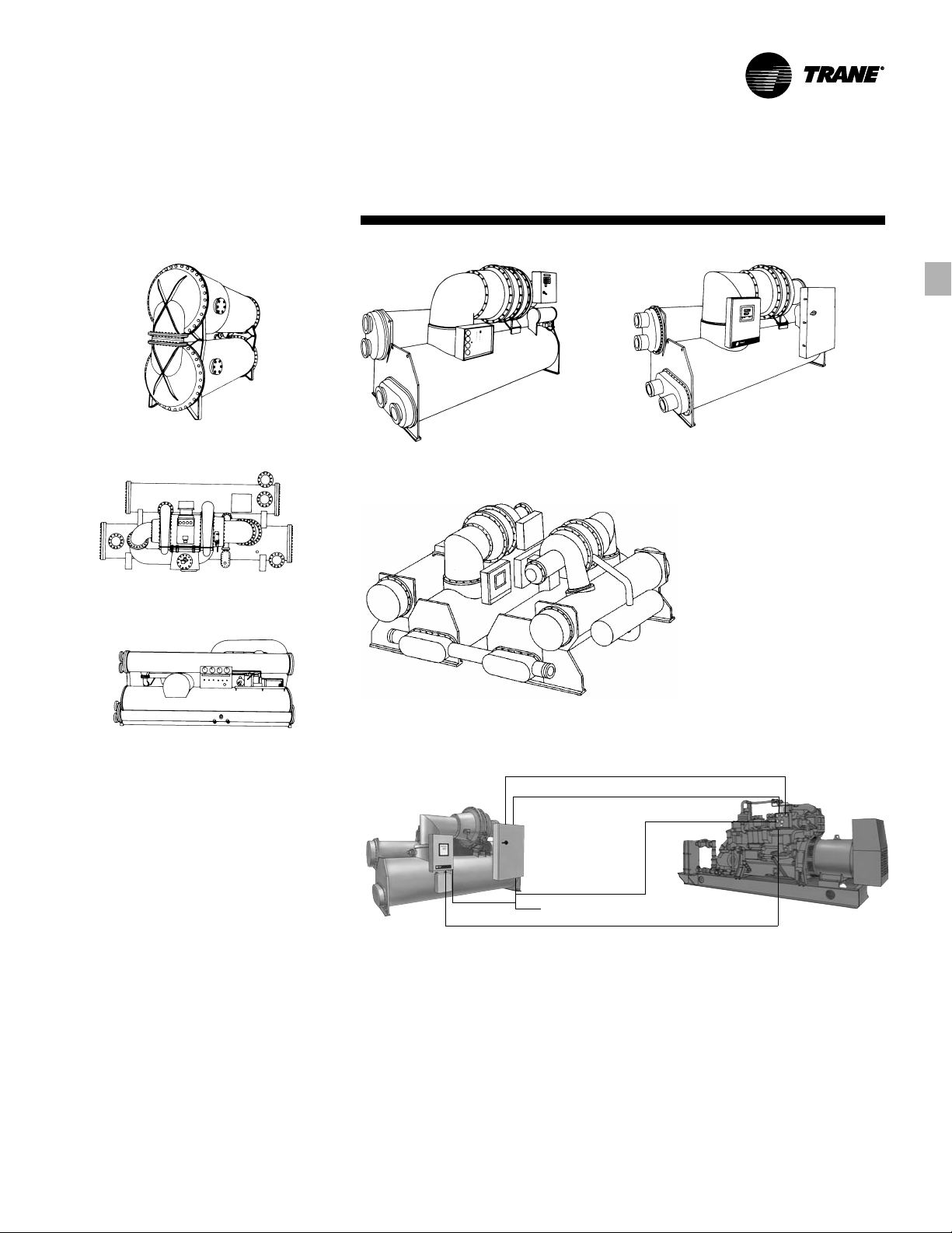
1939 — The Trane Turbovac
1951 — The original Trane CenTraVac
chiller
1965 — The Model PCV CenTraVac
chiller
Specific Trane centrifugal chiller
performance is certified by ARI Standard
550/590. Trane centrifugal chillers tested
within the scope of the ARI program
display the ARI symbol of compliance
(shown on back cover) to certification
sections of ARI Standard 550/590.
™
Purifier
rated in accordance with ARI
Standard 580.
Those applications in this catalog
specifically excluded from the ARI
certification program are:
•
•
•
•
•
•
•
purge with Purifier Plus™ are
Low temperature applications,
including ice storage
Glycol
Chillers above 2000 tons
Free cooling
Heat recovery
Auxiliary condenser
Chillers that are 50 Hertz
1992 — The two-stage CVHF CenTraVac
1982 — The three-stage CVHE CenTraVac
Chiller
1992 — The LHCV CenTraVac Modular Chiller system
//
115 VAC/60 Hz/50 Hz
//
1997 — The Gas Powered CenTraVac (GPC) Chiller Package
Chiller
3 Phase Power
Control Interface
Control Interface
CTV-PRC007-EN
5
Page 6
Attributes of
Features and Benefits
Comparing the Attributes of
Low Pressure Chiller Operation
to High Pressure Chiller
Operation.
Trane CenTraVac chillers continue to offer
time tested and proven low pressure
refrigerants including the alternative
Evaporator
Condenser
Monitoring
of leak rate in-leakage with a purge timer — periodic leak checks
Typical
Pressures Evap: 18.7 inches of Mercury Evap: 33.1 psig
(38°F evap.) Cond: 6.1 psig Cond: 124.1 psig
(100°F cond.)
*Trane Purifier Purge efficiency does not exceed 0.002 lbs./refrigerant/lbs.-air
Low Pressure Medium/High Pressure
Always at low negative pressure
•
Air leaks inward at low rate
•
Refrigerant lost: (# air leak in) x purge efficiency*
•
No refrigerant loss is into equipment room (vented to the
•
outside via purge)
At positive pressure during operation
•
Usually at negative pressure during inactivity (air leaks
•
inward)
Refrigerant leaks outward at very low rate during operation
•
Trane Purifier Purge is able to continuously monitor
•
Refrigerant monitor as required by ASHRAE — purchase refrigerant monitor
•
Purge timer can be connected to building automation
•
system for notification of increased purge operation (inleak). Similarly, the refrigerant monitor can be connected to pressure chiller is during spring start-up. This means that a
the building automation system. chiller which develops a leak in the summer, may leak
HCFC-123 HFC-134a
environment friendly HCFC- 123. Trane
CenTraVac chillers provide the safety of
low pressure with continued product
improvement in leak proof design.
Consider the following benefits of low
pressure over high pressure chillers.
Always at positive pressure
•
Refrigerant leaks outward at moderate rate
•
Refrigerant loss is into equipment room
•
Always at high positive pressure
•
Refrigerant leaks outward at very high rate
•
Only ways to monitor leak rate on high pressure chiller are
•
Refrigerant monitor as required by ASHRAE
•
Normally the only time that a leak is detected on a high
•
continuously until the following spring.
Low Pressure
Chiller Operation
CTV-PRC007-EN6
Page 7
Features and
Control
Benefits
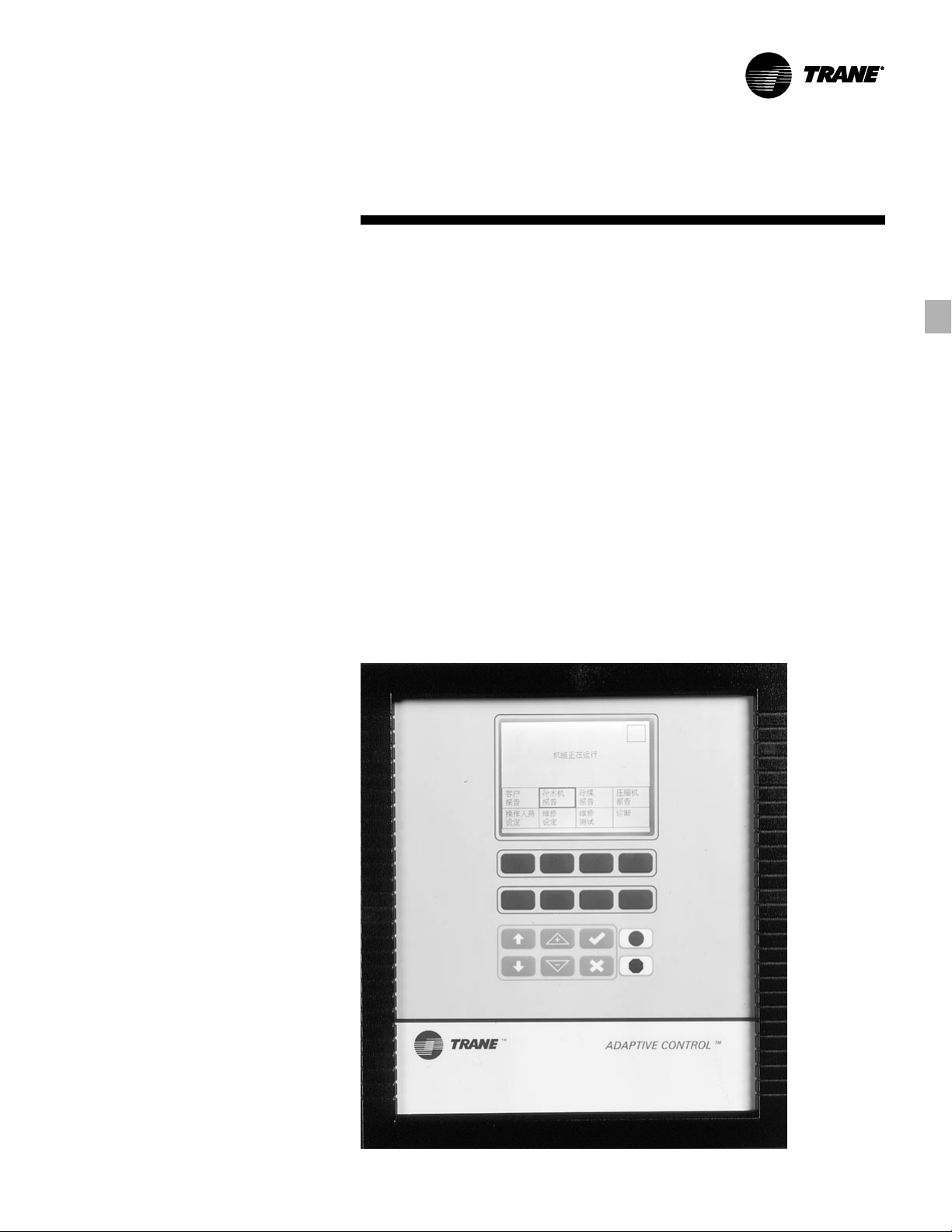
Operator Control Panel
Trane has multi-language support for all
chillers controlled by the UCP2
including but limited to: CVHE, CVHF,
CVHG, GPC and LHCV alarm. The
standard Clear Language Display (CLD)
supports eight languages including
English, French, German, Spanish,
Katakana, Italian, Portuguese and Dutch.
The Complex Character CLD was added
to support languages such as Traditional
and Simplified Chinese, Japanese, Thai
and Korean.
The Complex Character CLD is available
as a retrofit kit for the standard CLD on
the UCP2 panel. With the same wiring
and mounting, it is as simple as
disconnecting two wires, unbolting the
existing CLD, bolting on the Complex
Character CLD and reconnecting the two
wires.
™
Panel
Capabilities include:
Super-twist LCD display with
•
backlighting for readability.
Chiller data (more than 200 items)
•
including:
- Status
- Setpoints
- Field start-up items
- Machine configuration items
- Service test items
Status reports:
•
- Chiller Report
- Refrigerant Report
- Compressor Report
Custom report capability.
•
More than 100 diagnostic messages
•
including a history log of the last 20
diagnostics
- An alarm indicator
- Expanded help messages
- Operator security
- Internationally recognized symbols
CTV-PRC007-EN
7
Page 8
Features and
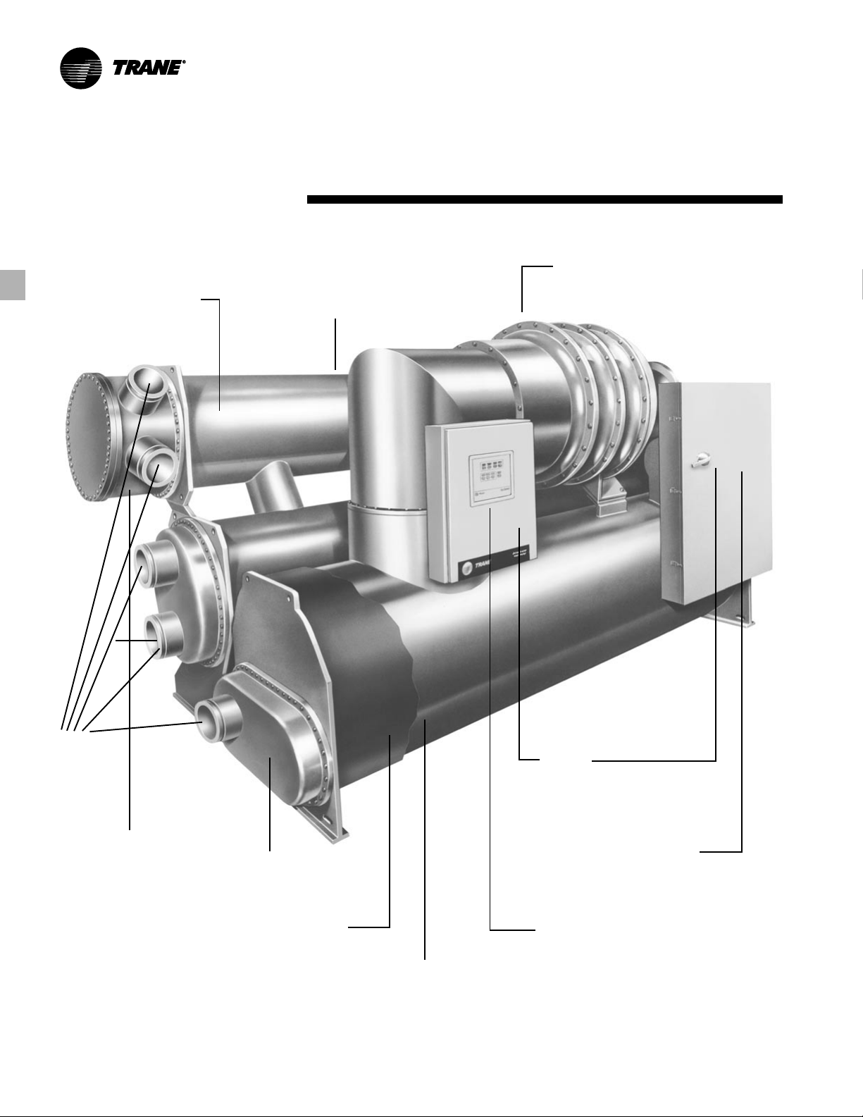
Internally enhanced or
smooth bore tubes
Benefits
Various tube materials
and thicknesses
Components
Controls and paints for outdoor
use or corrosive environments
Victaulic or
flanged
connections
Marine or standard
waterboxes
1, 2, 3, pass evaporator
Factory installed insulation
Special construction to facilitate
chiller disassembly for construction
projects with tight space clearances
or component weight limitations
UL label
Full complement of electrical
starters and accessories
(unit mounted or remotely)
- Panel chilled water reset
- External chilled water and current limit
setpoints
- Evaporator / Condenser differential
pressure
- Condenser relief request
- Maximum capacity
- Communication link to BAS
- Printer module
CTV-PRC007-EN8
Page 9

Standard
Features and
Benefits
Standard Features
The following features are provided as
standard with all Trane CenTraVac
chillers:
Motor-compressor assembly with
•
integral lubrication system.
Evaporator condenser assembly.
•
Two-stage economizer assembly on
•
CVHE/CVHG style units (single-stage on
CVHF style units).
Prewired instrument and control panel.
•
Oil and refrigerant charge.
•
Oil heater.
•
Isolation pads
•
Wiring and conduit for purge and oil
•
system interconnection to the main
control panel.
Installation, operation, and
•
maintenance instructions.
Start-up and operator instruction
•
service.
Advanced motor protection.
•
CenTraVac Motor
The motor provided in the Trane
CenTraVac chiller is a specially designed
squirrel cage, two pole induction motor
suitable for 50 and 60 hertz, three-phase
current.
Trane CenTraVac motors are cooled by
liquid refrigerant surrounding the motor
windings and rotor. Use of liquid
refrigerant results in uniform low
temperatures throughout the motor,
thereby promoting long motor life.
Refrigerant/Oil Pump Motor
The oil pump motor is a 120 volt,
50/60 hertz,
protective fusing and panel mounted
contactor.
Purge
The purge unit motor is a 120 volt,
50/60 hertz,
integral overload protection and panel
mounted contactor.
The use of an air-cooled condensing unit
obtains separation temperatures in the
purge drum as low as 0°F. Normal
operating efficiency does not exceed
0.002 lbs. of refrigerant lost per pound of
dry air removed. The purge system can
be operated at any time, independent of
chiller operation.
3
/4 hp, 1 phase motor with
3
/4 hp, 1 phase motor with
™
and Optional
Features
Optional Features
Trane offers a selection of optional
features to either complete the basic
chiller installation or to allow
modification for special purpose
applications.
Medium voltage (over 600 volts)
•
hermetic compressor motor
construction.
Complete line of compressor motor
•
starters.
Unit mounted starter accessory on low
•
voltage units up to an RLA of
1080 amps.
Marine waterboxes for evaporators
•
and condensers
High pressure (300 psig working
•
pressure) water side construction.
Free cooling.
•
Heat recovery or auxiliary condensers.
•
Smooth bore tubing.
•
Factory-applied thermal insulation
•
One-inch deflection spring isolators for
•
vibration-sensitive installations.
Building automation systems (BAS)
•
interface
Variable speed drives
•
Internally enhanced tubes
•
Various tube wall thicknesses
•
UL Label
•
Three pass evaporator/one pass
•
evaporator
Special construction to facilitate chiller
•
disassembly at the job
CuNi Tubes
•
Special paint and controls for outdoor
•
use or corrosive environments
Unit mounted refrigerator monitor
•
CTV-PRC007-EN
9
Page 10
Factory
Factory Testing for
Assured Performance
To prove that your chiller will perform as
promised, Trane offers factory
performance testing, which you can
witness.
Trane provides laboratory-grade,
calibrated performance testing on
ARI approved test loops that proves the
performance of the chiller tailored to
your application. The test provides:
Confirmed efficiency
•
Confirmed capacity
•
Smooth trouble-free start-up confirmed
•
through factory testing and
commissioning of both chiller and
controls
Trane believes centrifugal chiller testing
is so important that we invested over $2
million in CenTraVac testing facilities.
Testing is in accordance with ARI
Standard 550/590 and calibration of
instrumentation meets or exceeds the
National Institute of Standards
Technology (NIST).
The industry has responded to the
demand for more efficient chillers by
developing machines with component
mix-matching and many money saving
options. It’s possible that with the
thousands of component combinations
available, a specific chiller combination
may be laboratory tested for the first
time.
Trane offers two levels of CenTraVac
performance testing:
A performance test at design
•
conditions plus a certified test report.
A customer-witnessed performance
•
test at design conditions plus a certified
test report.
Trane is part of the ARI 550/590
certification program. The selection
program and machines bear the ARI seal
of approval. Performance testing is a key
part of this program. While the
certification program is technically
sound, a factory run test, with your
machine on the test stand, is still the best
way to confirm machine performance
and a trouble-free start-up.
Features and
Benefits
The single package design of the
CenTraVac chiller allows testing of each
assembled chiller at the factory. Actually
all components including the evaporator,
condenser, compressor and control
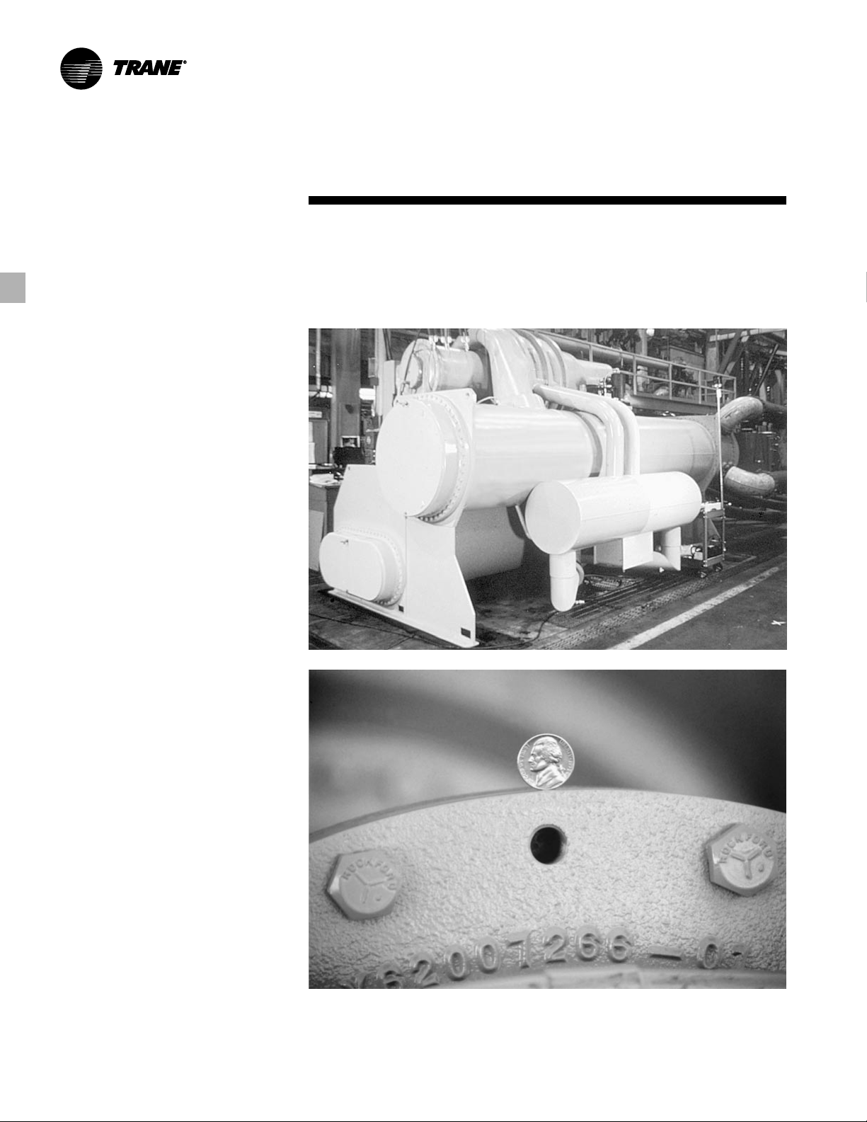
During customer witnessed performance tests of Trane CenTraVac chillers, a nickel
can be balanced on the edge of the compressor-motor assembly, demonstrating the
extremely low vibrations generated by the unit while operating at full and part load
conditions.
Performance
Testing
panel are tested before final assembly.
After assembly, performance testing of
the chiller can confirm proper operation
and virtually eliminate jobsite start-up
problems.
CTV-PRC007-EN10
Page 11
Features and
Refrigeration
Design Simplicity
Impellers are keyed directly to the motor
shaft for high reliability and performance
and low life-cycle costs.
Reliable Motor Cooling
The motor is engulfed in liquid
refrigerant to provide efficient, complete
cooling at all load conditions. This
system is reliable and easy to maintain.
Fixed Orifice Flow Control
For proper refrigerant flow control at all
load conditions, the CenTraVac design
incorporates the Trane patented fixed
orifice system. It eliminates float valves,
thermal expansion valves and other
moving parts. Since there are no moving
parts, reliability is increased.
Quiet Operation
With only one moving component — the
rotor and impeller assembly — the Trane
low speed, direct drive design operates
exceptionally quietly. The smoothly
rotating CenTraVac compressor is
inherently quieter than other compressor
types. Typical CenTraVac chiller sound
measurements are among the quietest in
the industry. Trane can guarantee sound
levels with factory testing and
measurements in accordance with
ARI standard 575.
The Reliability Standard
Just as a multi-stage turbine is more
efficient than a single stage turbine, the
CenTraVac multi-stage compressors are
more efficient and reliable than singlestage designs.
Benefits
Cycle
The CenTraVac™ Chiller Operating Cycle
Direct Drive Design — No Gear Losses
The direct drive compressor operates
without speed increasing gears, thus
eliminating gear energy losses.
Compressors using gears suffer mesh
losses and extra bearing losses in the
range of three to five percent at full load.
Since these losses are fairly constant
over the load range, increasingly larger
percentage losses result as load
decreases.
Multiple Stages of Compression
The compressor operates more
efficiently over a wide range of
capacities, virtually eliminating the need
for energy wasting hot gas bypass as
typically found on single stage chillers.
The radial component of velocity
determines the ability of the chiller to
resist interruption of smooth refrigerant
flow when operating at light loads and
with high condensing temperatures. This
interruption in flow and unstable
operation, called “surge” is avoided with
the two-stage design.
Inlet Guide Vanes
Part load performance is further
improved through use of moveable
designed variable inlet guide vanes. Inlet
guide vanes improve performance by
throttling refrigerant gas flow to exactly
meet part load requirements and by
prerotating refrigerant gas for optimum
entry into the impeller. Prerotation of
refrigerant gas minimizes turbulence and
increases efficiency.
Two-Stage Economizer
The CVHE/CVHG CenTraVac chiller has a
two-stage economizer — providing up to
seven percent greater efficiency than
designs with no economizer. Since the
CVHE/CVHG uses three impellers, it is
possible to flash refrigerant gas at two
intermediate pressures between the
evaporator and condenser pressures,
significantly increasing chiller efficiency.
This improvement in efficiency is not
possible in single-stage chillers since all
compression is done by one impeller.
Single Stage Economizer
The CVHF CenTraVac chiller has a singlestage economizer — providing up to 4
percent greater efficiency than designs
with no economizer.
Since the CVHF CenTraVac uses two
impellers, it is possible to flash
refrigerant gas at an intermediate
pressure between the evaporator and
condenser pressures, significantly
increasing chiller efficiency. This
improvement in efficiency is not possible
in single-stage chillers since all
compression is done by one impeller.
1
/2
CTV-PRC007-EN
11
Page 12
Features and
Refrigeration
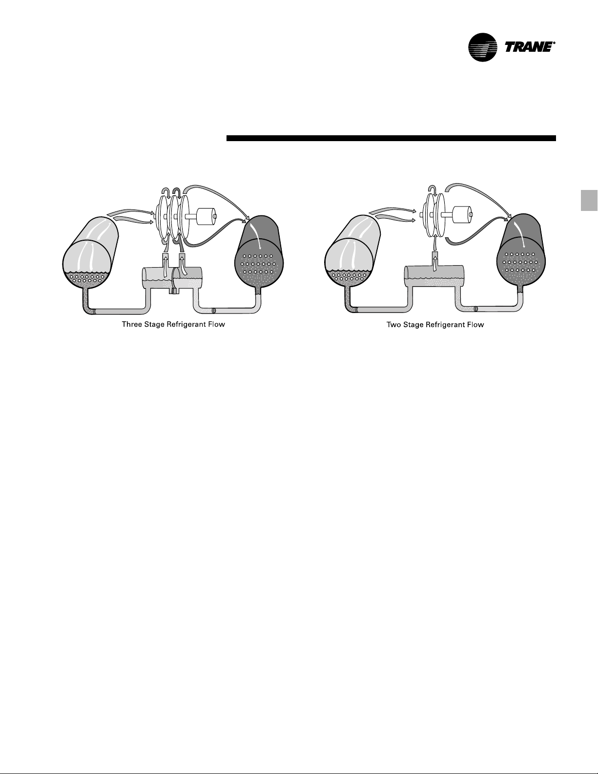
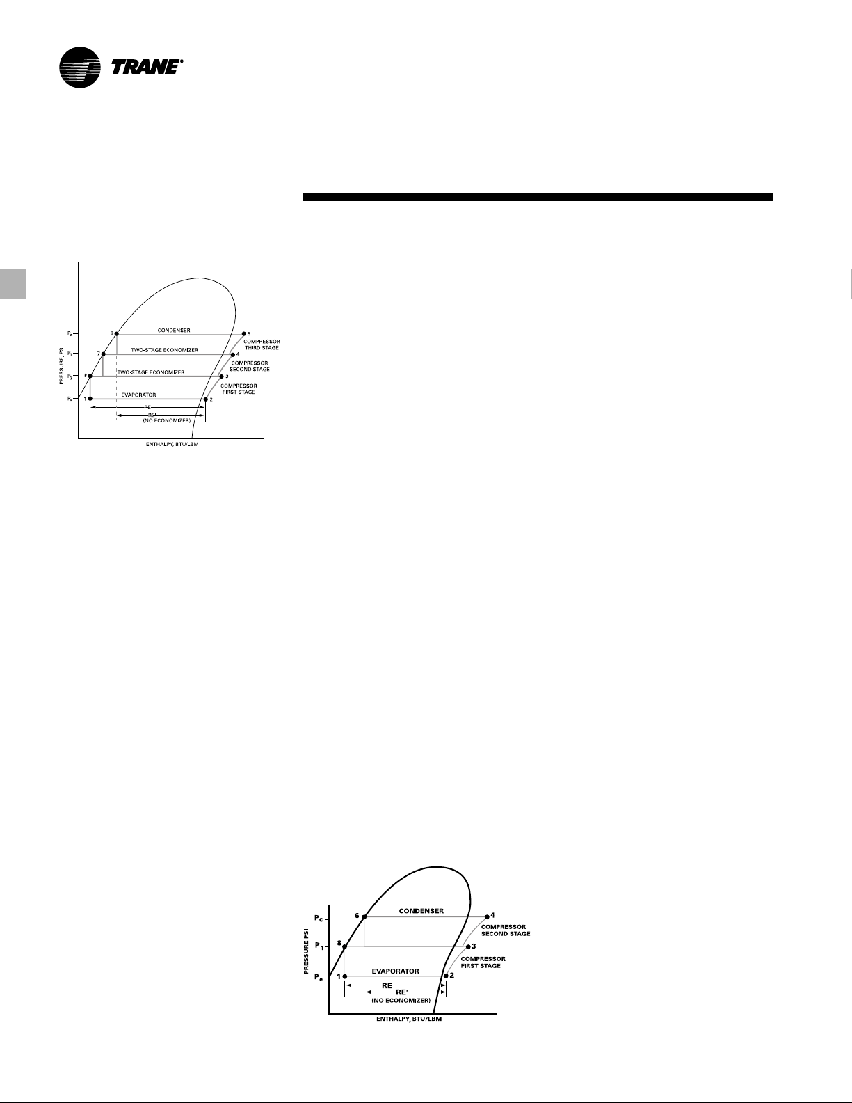
Three-Stage CenTraVac P-H Diagram
CenTraVac™ Three-Stage P-H Diagram
The pressure-enthalphy (P-H) diagram
describes refrigerant flow through the
major CVHE/CVHG chiller components.
This diagram confirms the superior
operating cycle efficiency of the threestage compressor and two-stage
economizer.
Evaporator — A liquid-gas refrigerant
mixture enters the evaporator at state
point 1. Liquid refrigerant is vaporized to
state point 2 as it absorbs heat from the
system cooling load. The vaporized
refrigerant then flows into the
compressor first stage.
Compressor First Stage — Refrigerant
gas is drawn from the evaporator into
the first stage compressor. The first stage
impeller accelerates the gas increasing
its temperature and pressure to state
point 3.
Compressor Second Stage —
Refrigerant gas leaving the first stage
compressor is mixed with cooler
refrigerant gas from the low pressure
side of the two-stage economizer. This
mixing lowers the enthalpy of the
mixture entering the second stage. The
second stage impeller accelerates the
gas, further increasing its temperature
and pressure to state point 4.
Compressor Third Stage — Refrigerant
gas leaving the compressor second
stage is mixed with cooler refrigerant
gas from the high pressure side of the
two-stage economizer. This mixing
lowers the enthalpy of the gas mixture
entering the third stage compressor. The
third stage impeller accelerates the gas,
Benefits
further increasing its temperature and
pressure to state point 5, then discharges
it to the condenser.
Condenser — Refrigerant gas enters the
condenser where the system cooling
load and heat of compression are
rejected to the condenser water circuit.
This heat rejection cools and condenses
the refrigerant gas to a liquid at state
point 6.
Patented Two-Stage Economizer and
Refrigerant Orifice System-Liquid
refrigerant leaving the condenser at state
point 6 flows through the first orifice and
enters the high pressure side of the
economizer. The purpose of this orifice
and economizer is to preflash a small
amount of refrigerant at an intermediate
pressure called P1. P1 is between the
evaporator and condenser pressures.
Preflashing some liquid refrigerant cools
the remaining liquid to state point 7.
Refrigerant leaving the first stage
economizer flows through the second
orifice and enters the second stage
economizer. Some refrigerant is
preflashed at intermediate pressure P2.
Preflashing the liquid refrigerant cools
the remaining liquid to state point 8.
Another benefit of preflashing refrigerant
is to increase the total evaporator
refrigeration effect from RE’ to RE. The
two-stage economizer provides a seven
percent energy savings compared to
chillers with no economizer.
To complete the operating cycle, liquid
refrigerant leaving the economizer at
state point 8 flows through a third orifice
system. Here, refrigerant pressure and
temperature are reduced to evaporator
conditions at state point 1.
Two-Stage CenTraVac P-H Diagram
Cycle (Cont.)
CenTraVac Two-Stage P-H Diagram
The pressure-enthalphy (P-H) diagram
describes refrigerant flow through the
major CVHF chiller components. This
diagram confirms the superior operating
cycle efficiency of the two- stage
compressor and economizer.
Evaporator — A liquid-gas refrigerant
mixture enters the evaporator at state
point 1. Liquid refrigerant is vaporized to
state point 2 as it absorbs heat from the
system cooling load. The vaporized
refrigerant then flows into the
compressor first stage.
Compressor First Stage — Refrigerant
gas is drawn from the evaporator into
the first stage compressor. The first stage
impeller accelerates the gas increasing
its temperature and pressure to state
point 3.
Compressor Second Stage —
Refrigerant gas leaving the first stage
compressor is mixed with cooler
refrigerant gas from the economizer.
This mixing lowers the enthalpy of the
mixture entering the second stage. The
second stage impeller accelerates the
gas, further increasing its temperature
and pressure to state point 4.
Condenser — Refrigerant gas enters the
condenser where the system cooling
load and heat of compression are
rejected to the condenser water circuit.
This heat rejection cools and condenses
the refrigerant gas to a liquid at state
point 6.
Economizer and Refrigerant Orifice
System-Liquid refrigerant leaving the
condenser at state point 6 flows through
the first orifice and enters the
economizer. The purpose of this orifice
and economizer is to preflash a small
amount of refrigerant at an intermediate
pressure called P1. P1 is between the
evaporator and condenser pressures.
Preflashing some liquid refrigerant cools
the remaining liquid to state point 8.
Another benefit of flashing refrigerant is
to increase the total evaporator
refrigeration effect from RE’ to RE. The
economizer provides a 4
energy savings compared to chillers with
no economizer. To complete the
operating cycle, liquid refrigerant leaving
the economizer at state point 8 flows
through a second orifice system. Here,
refrigerant pressure and temperature are
reduced to evaporator conditions at state
point 1.
1
/2 percent
CTV-PRC007-EN12
Page 13

Unit
Unit Mounted
Unit-Mounted Starters
Trane factory installed options make
installation of a CenTraVac™ chiller easier,
faster and less costly. Another example
of the Trane packaged concept is the
factory installed unit-mounted star delta
starter available on CenTraVac chillers up
to 1300 tons capacity or solid-state
starters up to 1000 tons, depending on
jobsite electrical requirements. It’s a
single chiller/starter package designed
for years of reliable operation and low
life-cycle costs.
Installation cost is reduced by eliminating
chiller-to-starter, starter-to-disconnect
and starter-to-control panel field wiring.
All this wiring is completed and tested in
the factory, ensuring electrical integrity.
Since most wiring is factory completed,
electrical system design time is reduced.
Starter components are pre-engineered
and selected to provide a reliable, cost
effective chiller/starter package. This
single source responsibility for the
CenTraVac chiller and unit-mounted
starter package is a real advantage.
Potential scheduling problems
associated with separate starter and
chiller installations are eliminated. When
the CenTraVac chiller arrives at the
jobsite with the unit-mounted starter, the
only remaining wiring is the main power
wiring to the disconnect switch, and a
few simple electrical interlocks to the
chilled water and condenser water flow
sensing devices.
To ensure a trouble-free start-up on the
electrical side, the unit-mounted starter is
tested with the chiller as part of the
factory performance testing program.
Our commitment to customer and
equipment safety offers the Underwriters
Laboratories Inc. (UL) mark of safety on
both chiller and starter and available
accessories.
Compressor Motor Starting Equipment
Features
Trane can provide compressor motor
starting equipment built to rigid Trane
specifications. The types of starters
available include:
Low Voltage (200 to 600 volts)
Star (wye)-delta closed transition
•
Full voltage
•
Options
Autotransformer, closed transition
•
Solid-state starters
•
Medium Voltage (2300 to 6000 Volts)
Full voltage
•
Primary reactor, closed transition
•
Autotransformer, closed transition
•
Medium voltage starters are provided as
standard with a non-load break isolation
switch and current limiting fuses.
All starters provided by Trane include the
following standard features for safe,
efficient application and ease of
installation:
NEMA 1 starter enclosure.
•
120 volt, 60 hertz, 1 phase fused pilot
•
and safety circuits.
Control power transformer (4.0 KVA)
•
with 120 volt, 50 or 60 hertz, singlephase.
One pilot relay to initiate start
•
sequence from CenTraVac control
circuit signal.
Starter enclosures capable of being
•
padlocked.
Automatic transfer from wye to delta
•
on any two-step starter.
In addition, Trane offers a wide selection
of optional starter features.
Starters with standard or high
•
interrupting capacity circuit breakers,
to provide disconnect means and short
circuit protection (low voltage only).
Ammeters and voltmeters.
•
Special function pilot lights.
•
Special NEMA enclosures.
•
Ground fault protection.
•
Power factor correction capacitors.
•
I.Q. Data Plus monitor device.
•
If the CenTraVac compressor starting
equipment is provided by others, the
starter must be designed in accordance
with the current Trane standard
engineering specification “Water-Cooled
CenTraVac
also recommended that two copies of
the interconnecting and control circuit
wiring diagrams be forwarded to The
Trane Company for review. This service
is provided at no charge, and is intended
to help minimize the possibility that
Trane CenTraVac chillers will be applied
in improper starting and control
™
Starter Specification.” It is
Starter
systems. However, the responsibility for
providing proper starting and control
systems must remain with the system
designer and the installer.
Contact your local Trane sales office for
further information.
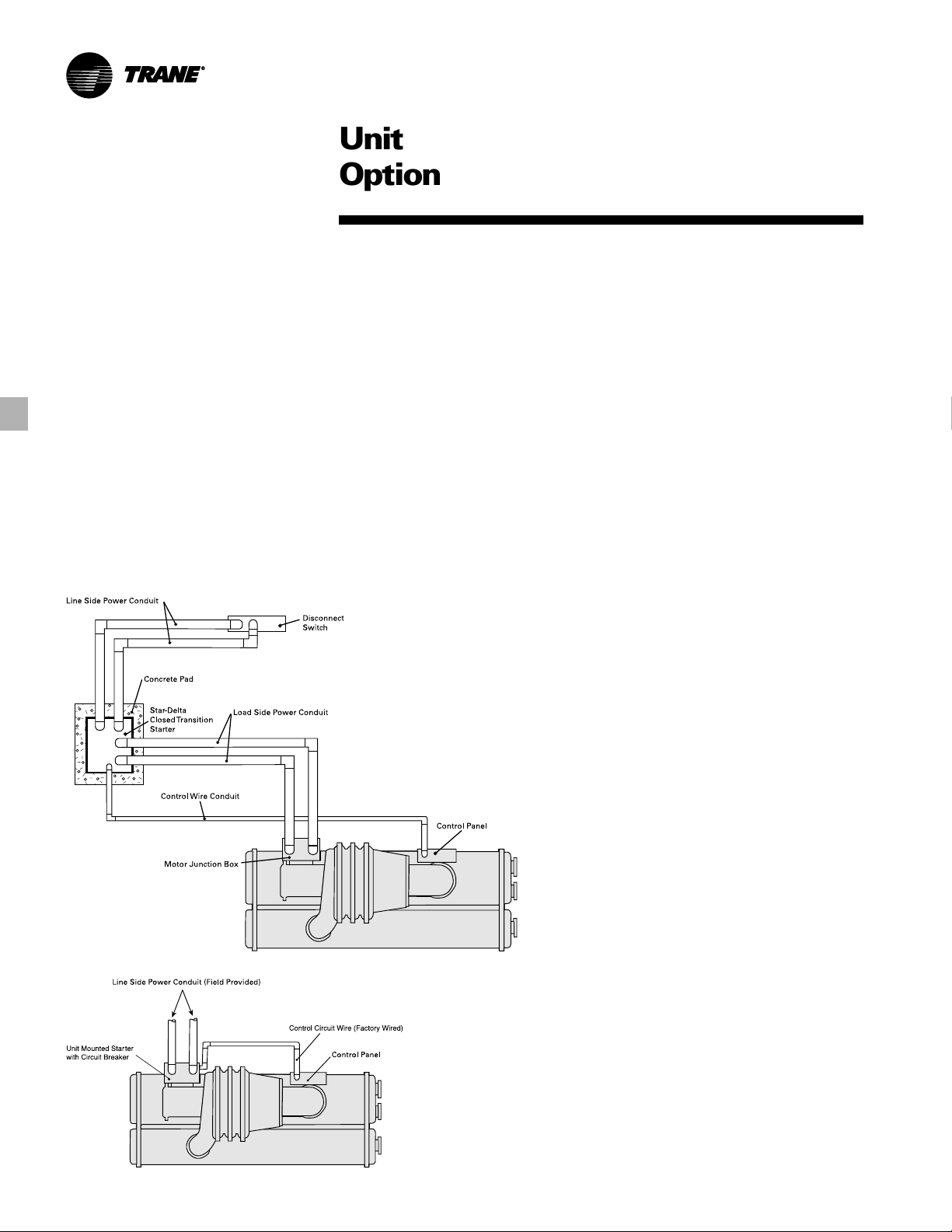
The typical equipment room layout for a
Trane CenTraVac
mounted starter are shown in Figures
O-1 and O-2. A NEMA 1, star-delta (wyedelta) type closed transition reduced
voltage motor starter is mounted, as an
optional accessory, on Trane CenTraVac
chillers rated up to and including 1080
RLA on low voltage (600 volts and
below) systems. All power and control
wiring between the starter and the chiller
are factory assembled. Factory assembly
enhances total system reliability and
integrity. Total installed chiller/starter
costs are significantly reduced by the
unit mounted starter option rather than a
conventional remote mounted starter.
Benefits
Reduces starter installation costs 20 to
•
35 percent:
By eliminating chiller-to-starter field
•
wiring
By eliminating starter-to-disconnect
•
switch field wiring (when optional
circuit breaker is used)
By eliminating field installed
•
disconnect switch (when optional
circuit breaker is used)
By eliminating starter mounting pad
•
and required equipment room floor
space
By eliminating control wiring from
•
starter to control panel
Electrical system reliability is
•
enhanced:
By reducing the number of field
•
electrical connections
By making starter-to-chiller electrical
•
connections under factory-controlled
conditions
By testing the entire chiller/starter
•
combination, in the factory
By providing control components
•
designed to operate with the unique
CenTraVac motor/compressor start and
protection subsystem
Single Source Responsibility
•
Trane retains complete responsibility
for the starter and associated chiller/
starter interconnecting wiring.
™
unit or remote
CTV-PRC007-EN
13
Page 14
Unit
Unit Mounted
Options
System Design Time Cost Savings
•
System design time is reduced, since
all starter components and
interconnecting wiring are preengineered and selected.
Complete package available with
•
Agency Approval
Application
•
The Trane unit mounted starter can be
applied on low voltage (600 volts) and
below applications up to
approximately 1300 tons capacity. To
determine the unit mounted starter to
be used with a particular selection, it is
necessary to know the current draw of
the compressor motor. The starter
current draw must be greater than, or
equal to, the compressor motor
current draw.
Figure O-1 – Typical Equipment Room Layout – Conventional Remote Star-Delta Starter
Figure O-2 – Typical Equipment Room Layout – Unit-Mounted Star-Delta Starter
Reliability
•
The unit mounted starter is a star-delta
closed transition electromechanical
starter. Motor starters of this
configuration have proven reliability in
thousands of centrifugal chiller
applications around the world. The
proven electromechanical concept plus
the use of industrial quality
components makes the CenTraVac unit
mounted starter dependable in all kinds
of service applications.
Operation
The unit mounted starter is a star (wye)
delta, closed transition, reduced voltage
starter. When starting and during
acceleration, the motor is connected in
its wye configuration. Because of this
arrangement the voltage applied to the
Starter (Cont.)
motor windings is reduced to one
divided by the square root of three or
0.58 times line voltage. This reduction in
winding voltage results in a reduction in
inrush current. The inrush current is 0.33
times the full voltage locked rotor current
rating of the motor. The accelerating
torque of the motor is also reduced to
0.33 times the full voltage torque rating.
This is sufficient to fully accelerate the
compressor motor. The unit control
panel monitors motor current during
operation via current transformers
located in the starter enclosure. When
during acceleration the line current
drops to approximately 0.85 times rated
load current, transition is initiated. The
closed transition feature provides for a
continuous motor current flow during
transition by placing resistors in the
circuit momentarily. This prevents
buildup of damaging torques to the
system during this period. With the
completion of transition, the motor
windings are connected in the delta
configuration with full line voltage.
Three precision current transformers
monitor phase current. Contactor
position and various voltage signals
provide extensive interlocking between
the starter and the microcomputer in the
CenTraVac
subsequent instruction originate in the
unit control panel. Protection against the
following starter defects is provided:
High motor current (starting and
•
running)
Improper starter circuitry
•
Excessive accelerating time
•
Incomplete starting sequence
•
Loss of phase
•
Phase amperage unbalance
•
Phase reversal
•
Distribution fault
•
Features
The Trane CenTraVac Unit Mounted
Starter includes the following standard
features:
NEMA 1 enclosure, designed to
•
accommodate padlock
3 KVA control power transformer with
•
120V secondary
Fused 120V control circuit
•
3-phase incoming line terminals
•
6 output load terminals factory-
•
connected to the motor
™
control panel. All logic and
CTV-PRC007-EN14
Page 15
Unit
Unit Mounted
Available options include:
Circuit Breaker — A standard
•
interrupting capacity circuit breaker is
available. The circuit breaker is
mechanically interlocked to disconnect
line power from the starter when the
starter door is open.
High Interrupting Capacity Circuit
•
Breaker — A high interrupting capacity
circuit breaker is available. This breaker
is also interlocked to disconnect line
power from the starter when the
starter door is open.
Circuit Breaker with Ground Fault —
•
Ground Fault protection is available
with either standard or high
interrupting capacity circuit breakers.
An indicating light is provided to
indicate if a ground fault has occurred.
Current Limiting Circuit Breaker — A
•
standard circuit breaker incorporating
the current limiters with fuse links is
available. A fault current in excess of
the circuit breaker capacity will blow
the fuse links and interrupt the fault
current. The circuit breaker cannot be
reset until the blown current limiters
are replaced.
Ground fault detection and protection
•
(available only with circuit breaker
options)
Options
The solid-state starter controls the
starting characteristics of a motor by
controlling the current that flow to the
motor. It does so through the use of
SCRs (Silicon Controlled Rectifiers),
which are solid-state switching devices,
and an integral bypass contactor for
power control.
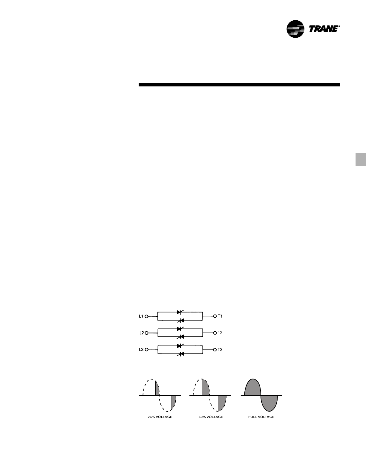
SCR’s
An SCR will conduct current in one
direction only when a control signal
(gate signal) is applied. Because the
solid-state starter is for use on AC
(alternating current), two SCR’s per
phase are connected in parallel,
opposing each other so that current may
flow in both directions. For three- phase
loads, a full six-SCR configuration is
used. The connection is shown in Figure
O-3.
During starting, control of current or
acceleration time is achieved by gating
the SCR on at different times within the
half-cycle. The gate pulses are originally
applied late in the half-cycle and then
gradually applied sooner in the halfcycle. If the gate pulse is applied late in
the cycle, only a small increment of the
wave form is passed through, and the
output is low.
Starter (Cont.)
If the gate pulse is applied sooner in the
cycle, a greater increment of the wave
form is passed through, and the output
is increased. So, by controlling the SCR’s
output voltage, the motor’s acceleration
characteristic and current inrush can be
controlled. These forms are shown in
Figure O-4.
Integral Bypass Contactors
When the SCR’s are fully “phased on,”
the integral bypass contactors are
energized. The current flow is transferred
from the power pole to the contactors.
This reduces the energy loss associated
with the power pole, which is otherwise
about one watt per amp per phase.
When the starter is given the stop
command, the bypass contactors are deenergized, which transfers the current
flow from the contactors back to the
power poles. Two-hundred fifty
milliseconds later, the SCR’s are turned
off, and the current flow is stopped.
CTV-PRC007-EN
Figure O-3 — Six-SCR Configuration
Figure O-4 — Wave Forms
15
Page 16
Unit
Adaptive
Benefits
Trane Adaptive Frequency drives*
provide motor control, but they are
much more than just starters. They also
control the operating speed of the chiller
compressor motor by regulating output
voltage in proportion to output
frequency. Varying the speed of the
compressor motor can translate into
significant energy cost savings.
Reliable, Optimized Compressor
Efficiency for Energy Savings
Conventional chillers use inlet vanes to
provide stable operation at part-load
conditions. Capacity is reduced by
closing the vanes while maintaining a
constant motor speed. The drive can be
used to significantly reduce power
consumption by reducing motor speed
at low load conditions. Trane patented
AFD Adaptive Control
allows inlet guide vane and speed
control combinations that optimize partload performance.
To Avoid Mechanical Stress
Controlled “soft” start with linear
acceleration results in limited starting
current to eliminate motor stress, reduce
power line disturbance and provide a
lower power demand on start. Reduced
motor speed as a result of reduced
chiller load means less current drawn,
less heat generated, increased motor
winding life. This translates into longer
time between compressor maintenance
and less downtime throughout the life of
the machine.
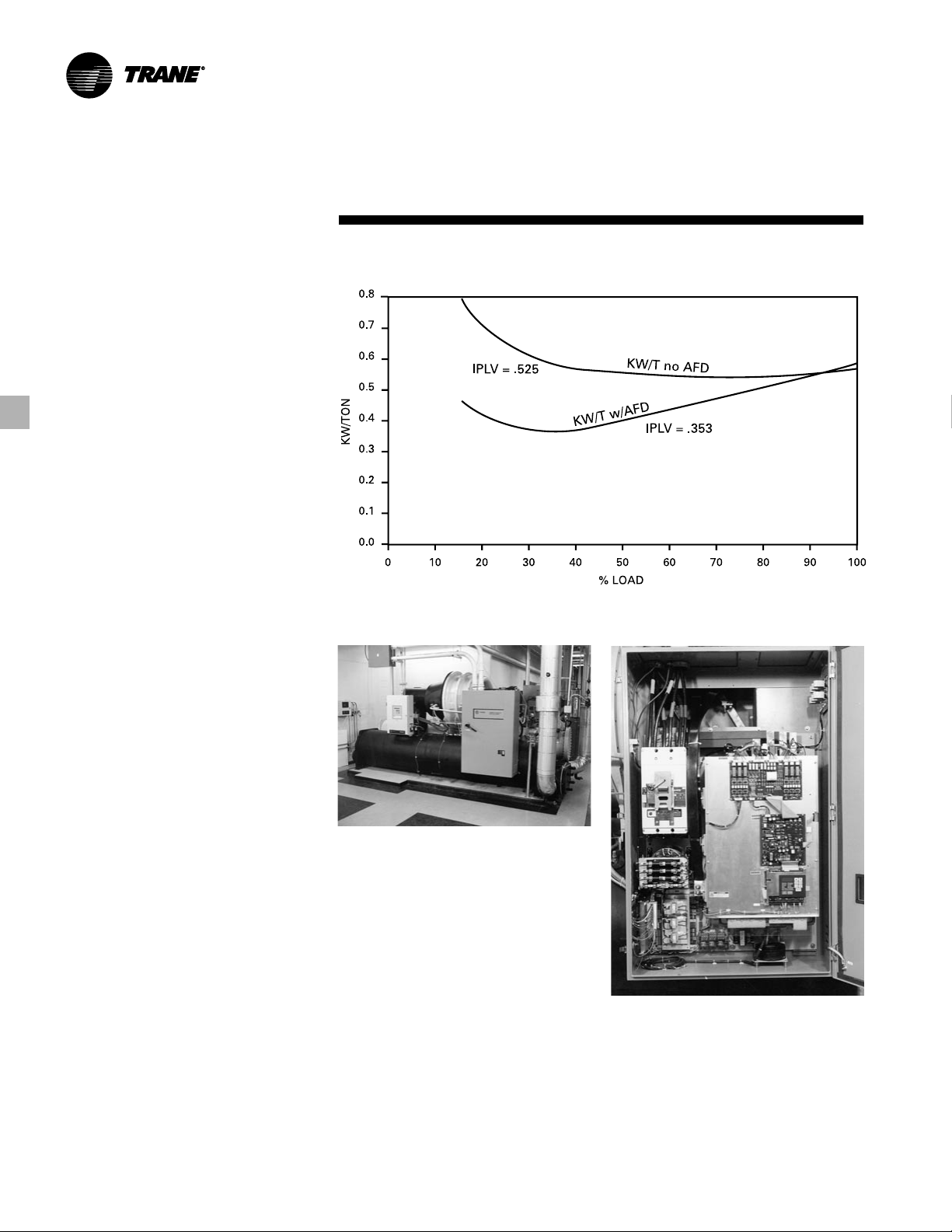
Application
Certain system characteristics favor
installation of an AFD because of energy
cost savings and shorter payback.
Among them are:
A large number of part-load operating
hours annually
Figure O-4, based on a CVHE500, 500-ton
load at standard ARI conditions, shows
that major kW savings occur at part-load
conditions, typically below 90 percent
load.
™
logic safely
Options
Figure O-4 — CVHE500 Part Load Efficiencies with/without AFD
Frequency Drives
CTV-PRC007-EN16
Page 17

Unit
Adaptive
Options
Condenser water temperature relief of
chilled water reset
Compressor lift reduction is required for
a chiller application, both to provide
stable chiller operation at part-loads and
to achieve greater energy savings.
Intelligent control to reduce condenser
water temperature, or chiller water reset
strategies are key to AFD savings in
chiller applications.
High kW Charges
Electric utility bills normally include both
demand and energy components. The
demand or kW portion is established by
usage during utility peak hours, by
individual peak usage or a combination.
This portion may or may not be
influenced by installation of an AFD. But
the energy or kWh portion will almost
certainly be reduced because of the
improved efficiency of the chiller plant
during part-load conditions throughout
the year. The greater the kWh charge, the
shorter the payback.
Operation
The Trane AFD controls the speed of the
chiller compressor by regulating the
output voltage in proportion to the
output frequency to provide a nominally
constant rate of voltage to frequency as
required by the characteristics of the
compressor motor. Motor speed is
proportional to this applied frequency.
The Trane AFD is a voltage source, pulsewidth modulated (PWM) design. It
consists of three basic power sections:
Converter — Semi-conductor bridge
•
rectifier takes incoming AC power and
converts it to a fixed voltage DC bus.
DC bus filter — The converted DC bus
•
voltage contains a significant amount
of ripple. The DC bus filter smooths the
voltage ripple from the converter with
capacitors and a DC link reactor to
supply a fixed constant voltage to the
inverter section. It also minimizes the
electrical harmonics generated by the
drive back to the distribution system.
Frequency Drives
Inverter — Converts the DC voltage
•
into a sinusoidal synthesized output
AC voltage. This synthesized output
controls both the voltage and
frequency which is applied to the
motor.
A fourth element of AFD design is the
microprocessor control logic which is
the intelligence for the power section. It
also includes all feedback sensors
required for stability in the system and
any required shutdown due to a fault.
Soft Start: Inrush Current and Torque
Trane AFD’s are programmed to start the
compressor motor from low frequency
and low voltage. The motor is brought
up to speed by increasing both
frequency and voltage at the same ratio.
Thus current and torque are much lower
during start-up and acceleration than the
high current, high torque associated with
across-the-line or even reduced voltage
starters.
Note that the actual torque developed by
the AFD is the total of the torque
required by the load and the accelerating
torque. The AFD is rated by output
current and is limited to a maximum of
100 percent continuous RLA through the
chiller control (UCP2). A 100 percent
output current capability results in 100
percent torque generated by the motor.
In other words, the drive regulates
output voltage in proportion to output
frequency to maintain ideal motor flux
and constant torque producing
capability.
CTV-PRC007-EN
17
Page 18

Unit
Free Cooling Allows
Reduced Operating Costs
Consider a CenTraVac™ chiller option that
can provide up to 45 percent of the
nominal chiller capacity — without
operating the compressor. Think of the
significant energy and cost savings
possible in many applications. This
option is available on all Trane chillers,
factory installed.
Free cooling operation is based on the
principle that refrigerant migrates to the
area of lowest temperature. When
condenser water is available at
temperatures lower than the required
leaving chilled water temperature
(typically 50 to 55°F), the unit control
panel starts the free cooling cycle
automatically.
When the free cooling cycle can no
longer provide sufficient capacity to meet
cooling requirements, mechanical
cooling is restarted automatically by the
unit control panel.
For example, a building with a high
internal cooling load is located in a
climate with cold winters. It is possible to
cool the building exclusively with free
cooling three to six months of the year!
Free cooling payback can easily be less
than a year.
Free cooling is completely factory
installed and requires no more floor
space or piping than the standard
CenTraVac chiller (unlike plate frame heat
exchangers).
Benefits
The Trane patented free cooling
accessory for Trane CenTraVac
adapts the basic chiller so it may
function as a simple heat exchanger
using refrigerant as the working fluid.
When condenser water is available at
temperatures lower than the desired
chilled liquid temperature, free cooling
can provide up to 45 percent of nominal
chiller capacity without operation of the
compressor. This feature may result in
substantial energy cost savings on many
installations.
™
chillers
Options
Free Cooling Operation Schematic
Reliability
Two simple valves are the only moving
parts.
Single-Source Responsibility
Free cooling is Trane engineered,
manufactured and installed.
Ease of Operation
Changeover on free cooling by single
switch control.
Ease of Installation
Completely factory-installed and leaktested components. All valve operators
and controls are factory wired.
Application
Modern buildings often require some
form of year-round cooling to handle
interior zones, solar loads, or computer
loads. As the outside air temperature
decreases below the inside air design
temperature, it is often possible to use
an outside air economizer to satisfy the
cooling requirements. There are a
number of instances, however, where
CenTraVac free cooling offers a number
of advantages over the use of an outside
air economizer. It is possible for the free
cooling chiller to satisfy the cooling load
for many hours, days, or months during
the fall, winter, or spring seasons without
operation of the compressor motor. This
method of satisfying the cooling
requirement can result in significant total
energy savings over other types of
systems. The savings available are most
easily determined through the use of a
computer energy analysis and economic
program, such as TRACE
Conditioning and Economics).
™
(Trane Air
Free Cooling
The suitability of free cooling for any
particular installation depends upon a
number of factors. The availability of
low temperature condensing water, the
quality of the outside air, the type of
airside system, the temperature and
humidity control requirements, and the
cost of electricity all have a direct impact
on the decision to use a free cooling
chiller.
The use of CenTraVac free cooling
depends on the availability of cold
condenser water from a cooling tower,
river, lake, or pond. As a general rule of
thumb, locations which have a
substantial number of days with
ambient temperatures below 45°F wet
bulb or more than 4000 degree-days per
year are well suited to free cooling
operation. A cooling tower usually must
be winterized for off-season operation
and the minimum sump temperature is
limited by some cooling tower
manufacturers. Cooling tower
manufacturers should be consulted for
recommendations on low temperature
operation. With river, lake or pond
supply, condenser water temperatures
down to freezing levels are possible.
Areas which have badly fouled air may
be more conducive to free cooling
operation than the use of an outside air
economizer.
Airside systems which both heat and
cool the air can often effectively use a
free cooling chiller. Dual-duct, multizone,
and reheat systems fall into this general
category. As the outside temperature
begins to fall, the cool outside air
satisfies the cooling requirements
(through an outside air economizer). As
the outdoor air temperature becomes
very low, the outdoor air may need to be
heated in order to maintain the design
supply air temperature when it is mixed
with return air. This “heating penalty”
can be eliminated by using CenTraVac
free cooling. Warm chilled water
temperatures provided by the free
cooling chiller would allow a warmer air
temperature off the chilled water coils,
eliminating the heating energy required
by using only an outside air economizer.
With today’s high cost electricity in most
areas of the country, this heating penalty
can be very significant.
CTV-PRC007-EN18
Page 19

Unit
Temperature and humidity control
requirements are important
considerations when evaluating the use
of CenTraVac free cooling. Low
temperature outside air (from the
outside air economizer) often requires a
large amount of energy for
humidification purposes. Free cooling
operation helps to reduce these
humidification costs on many
applications.
It is important to note that those
applications which require extremely
precise humidity control typically cannot
tolerate warmer than design chilled
water temperatures. Therefore, since
free cooling chillers normally deliver
warmer than design chilled water
temperatures, free cooling operation is
usually not applicable with systems
which require precise humidity control.
Also, free cooling is generally not used in
conjunction with heat recovery systems,
since mechanical cooling must be used
to recover heat that will be used
elsewhere in the building for
simultaneous heating.
Operation
Free cooling operates on the principle
that refrigerant flows to the area of
lowest temperature in the system. The
™
system/Chiller Plant Manager
Tracer
(CPM) can be used for automatic free
cooling control. When condenser water
is available at a temperature lower than
the required leaving chilled water
temperature, the CPM starts the free
cooling cycle. If the load cannot be
satisfied with free cooling, the CPM
or a customer supplied system can
automatically switch to the powered
cooling mode. If desired, the chiller
can be manually switched to the free
cooling mode at the unit control panel.
Upon changeover to free cooling, the
shutoff valves in the liquid and gas lines
are opened and a lockout circuit
prevents compressor energization.
Liquid refrigerant drains by gravity from
the storage tank into the evaporator,
flooding the tube bundle. Since the
refrigerant temperature and pressure
will be higher in the evaporator than in
the condenser, due to the water
temperature difference, the refrigerant
gas boiled off in the evaporator will flow
to the condenser. The gas then
CTV-PRC007-EN
Options
condenses and flows by gravity back to
the evaporator. This automatic
refrigeration cycle is sustained as long as
a temperature difference exists between
the condenser water and evaporator
water.
The difference in temperature between
the condenser and evaporator
determines the rate of refrigerant flow
between the two shells and hence the
free cooling capacity.
If the system load becomes greater than
the free cooling capacity either the
operator manually stops free cooling, a
binary input from a customer-supplied
system disables free cooling or the CPM
can automatically perform this function.
The gas and liquid valves close and the
compressor starts. Refrigerant gas is
drawn out of the evaporator by the
compressor, compressed and introduced
into the condenser. Most of the
condensed liquid first takes the path of
least resistance by flowing into the
storage tank which is vented to the high
pressure economizer sump by a small
bleed line. When the storage tank is
filled, liquid refrigerant must flow
through the bleed line restriction. The
pressure drop through the bleed line is
greater than that associated with the
orifice flow control device, hence liquid
refrigerant flows normally from the
condenser through the orifice system
and into the economizer.
The free cooling accessory consists of
the following factory-installed or
supplied components:
A refrigerant gas line, including an
•
electrically actuated shutoff valve,
installed between the evaporator and
condenser.
A valved liquid return line including an
•
electrically activated shutoff valve,
between the condenser sump and
evaporator.
A liquid refrigerant storage vessel.
•
Added refrigerant charge.
•
Manual free cooling controls on the
•
unit control panel.
For specific information on free cooling
applications, contact the local Trane sales
office.
Free Cooling
Figure O-5 — Compressor Operation
Schematic
Figure O-6 — Free Cooling Operation
Schematic
19
Page 20

System
Auxiliary
Options
Auxiliary Condenser
The Trane auxiliary condenser provides
economical heat recovery for
applications with small heating demand.
It’s well-suited to preheat applications
including domestic hot water, boiler
makeup water and swimming pools.
The Trane auxiliary condenser option
consists of a separate condenser
connected in parallel with the standard
condenser to provide simple heat
recovery capability for applications
where full heat recovery or high heating
water temperatures are not required.
Heat which normally would be rejected
to the regular condenser water is picked
up in the auxiliary condenser before the
water enters the hot water heating
system. Typical uses for this water
include domestic water preheat, boiler
makeup water preheat, and reheat air
conditioning systems, as opposed to
traditional heat recovery applications
where higher temperature water is used
to satisfy a building heating load,
provide full heat input for domestic hot
water, or provide the typically larger flow
rates of hot water for process
applications.
The auxiliary condenser not only
captures energy otherwise lost, it also
increases chiller efficiency.
Auxiliary condensers are available in two
sizes: standard and large. Because the
auxiliary condenser is a separate
condenser, there is no cross
contamination between the cooling
tower water and the heat recovery water
circuits.
No temperature controls are required.
Auxiliary condensers are factory
mounted and tested.
Condenser
Benefits
Simplicity
No temperature controls are required.
Auxiliary condensers are factorymounted and tested.
Flexibility
Two auxiliary condenser sizes are
available — standard and large. Either
auxiliary condenser can be applied to
any size CenTraVac
Safe
Because the auxiliary condenser is a
separate condenser, there is no
possibility of cross contamination
between the cooling tower water and the
auxiliary condenser water circuits.
Efficient
Use of the auxiliary condenser option
actually increases the chiller’s efficiency
by increasing condenser heat transfer
surface area and lowering the pressure
differential the compressor must
generate.
Decreased life cycle operating costs
result through use of the auxiliary
condenser option because heat, which
normally would be rejected by the
cooling tower circuit, is now used for
building heating requirements.
Application
A simultaneous demand for heating and
cooling is necessary to apply any heat
recovery system. Common uses for
heated water from an auxiliary
condenser include domestic water
preheat, reheat air conditioning systems,
and boiler makeup water. Building use is
not limited to the traditional heat
recovery candidates. Schools, hospitals,
office buildings, and hotels have all
proved to be excellent applications for
the auxiliary condenser option.
™
.
CTV-PRC007-EN20
Page 21

System
Auxiliary
Options
Controls
The auxiliary condenser was designed
for simplicity of operation. Machine load,
water flow rate, and temperature
determine the amount of heat recovered.
There are no controls needed for heating
water temperature because no attempt
is made to maintain a specific hot water
temperature in or out of the auxiliary
condenser.
Operation
The auxiliary condenser is a factorymounted, separate, shell and tube heat
exchanger available on water-cooled
CenTraVac chillers.
Because hot refrigerant gas always
migrates to the area of lowest
temperature, auxiliary condenser
operation is simple. As hot gas leaves
the compressor, it is free to flow to the
auxiliary condenser or the standard
condenser. Since water entering the
auxiliary condenser is normally colder
than that entering the standard
condenser, the auxiliary condenser will
have a lower bundle temperature and
will attract the refrigerant gas. The
auxiliary condenser will recover as much
heat as the machine cooling load,
Condenser (Cont.)
heating water temperature, and flow rate
will allow. All remaining heat will
automatically be rejected through the
standard condenser to the atmosphere
through the cooling tower. No controls
are needed to balance heat rejection in
the two condensers.
Good system design will include a
heated water bypass to ensure that
water does not circulate through the
auxiliary condenser when the chiller is
de-energized. There are several ways to
bypass the auxiliary condenser. When
the hot water system is installed as
shown in the figure below, the bypass is
automatic if the heating water pump is
interlocked with the chiller compressor
motor.
Another bypass arrangement is to install
a diverting valve. When interlocked with
the compressor motor, this valve diverts
the heating water flow to the
conventional heating system whenever
the chiller is not operating. These are
only examples of the many ways of
accomplishing a bypass.
Contact your local Trane sales office for
further specific information.
CTV-PRC007-EN
Table O-1 — Auxiliary Condenser Flow Limits and Connection Sizes
Auxiliary Two Pass
Condenser Inter Enhanced Smooth Bore Connection
Bundle Minimum Maximum Minimum Maximum Size
Size Gpm Gpm Gpm Gpm (In)
Standard 74 276 70 258 5
Large 121 453 115 423 5
21
Page 22

System
Ice Storage Provides
Reduced Electrical Demand
Ice storage is the hottest thing in cooling
today. It has been accepted by building
owners and tenants who are concerned
about utility costs.
An ice storage system uses a standard
chiller to make ice at night when utilities
charge less for electricity. The ice
supplements or even replaces
mechanical cooling during the day when
utility rates are at their highest. This
reduced need for cooling results in big
utility cost savings.
Another advantage of ice storage is
standby cooling capacity. If the chiller is
unable to operate, one or two days of ice
may still be available to provide cooling.
In that time the chiller can be repaired
before building occupants feel any loss
of comfort.
The Trane CenTraVac chiller is uniquely
suited to low temperature applications
like ice storage because it provides
multiple stages of compression.
Competitive chillers provide only one
stage. This allows the CenTraVac chiller
to produce ice efficiently, with less stress
on the machine.
Simple and smart control strategies are
another advantage the CenTraVac chiller
has for ice storage applications. Trane
™
building management systems
Tracer
can actually anticipate how much ice
needs to be made at night and operate
the system accordingly. The controls are
integrated right into the chiller. Two
wires and preprogrammed software
dramatically reduce field installation cost
and complex programming.
Trane centrifugal chillers are well suited
for ice production. The unique multistage compressor design allows the
lower suction temperatures required to
produce ice and the higher chiller
efficiencies attributed to centrifugal
chillers. Trane three stage and two stage
centrifugal chillers produce ice by
supplying ice storage vessels with a
constant supply of 22 to 24°F glycol.
Centrifugal chillers selected for these
lower leaving fluid temperatures are also
Options
selected for efficient production of
chilled fluid at nominal comfort cooling
conditions. The ability of Trane chillers to
serve “double duty” in ice production
and comfort cooling greatly reduces the
capital cost of ice storage systems.
A glycol solution is used to transfer heat
from the ice storage tanks to the
centrifugal chiller and from the cooling
coils to either the chiller or ice storage
tanks. The use of a freeze protected
solution eliminates the design time, field
construction cost, large refrigerant
charges, and leaks associated with ice
plants. Ice is produced by circulating 2224°F glycol through modular insulated
ice storage tanks. Each tank contains a
heat exchanger constructed of
polyethylene tubing. Water in each tank
is completely frozen with no need for
agitation. The problems of ice bridging
and air pumps are eliminated.
When cooling is required, ice chilled
glycol is pumped from the ice storage
tanks directly to the cooling coils. No
expensive heat exchanger is required.
The glycol loop is a sealed system,
eliminating expensive annual chemical
treatment costs. The centrifugal chiller is
also available for comfort cooling duty at
nominal cooling conditions and
efficiencies. The modular concept of
glycol ice storage systems and the
proven simplicity of Trane Tracer
controls allow the successful blend of
reliability and energy saving
performance in any ice storage
application.
Ice Storage Demand Cost Savings
™
Ice Storage
The ice storage system is operated in six
different modes: each optimized for the
utility cost of the hour.
1 Provide comfort cooling with chiller
2 Provide comfort cooling with ice
3 Provide comfort cooling with ice and
chiller
4 Freeze ice storage
5 Freeze ice storage when comfort
cooling is required
6 Off
Tracer optimization software controls
operation of the required equipment and
accessories to easily transition from one
mode of operation to another. For
example:
Even with ice storage systems there are
numerous hours when ice is neither
produced or consumed, but saved. In
this mode the chiller is the sole source of
cooling. For example, to cool the
building after all ice is produced but
before high electrical demand charges
take effect, Tracer sets the centrifugal
chiller leaving fluid setpoint to its most
efficient setting and starts the chiller,
chiller pump, and load pump.
When electrical demand is high, the ice
pump is started and the chiller is either
demand limited or shut down
completely. Tracer controls have the
intelligence to optimally balance the
contribution of ice and chiller in meeting
the cooling load.
The capacity of the chiller plant is
extended by operating the chiller and ice
in tandem. Tracer rations the ice,
augmenting chiller capacity while
reducing cooling costs.
When ice is produced, Tracer will lower
the centrifugal chiller leaving fluid
setpoint and start the chiller, chiller and
ice pumps, and other accessories. Any
incidental loads that persists while
producing ice can be addressed by
starting the load pump and drawing
spent cooling fluid from the ice storage
tanks.
For specific information on ice storage
applications, contact your local Trane
sales office.
CTV-PRC007-EN22
Page 23

System
Options
Heat Recovery
Use of the Heat Recovery CenTraVac
can significantly reduce the energy
operating costs of many buildings by
using heat which normally would be
rejected to the atmosphere. Typical uses
for this heat are perimeter zone heating,
reheat air conditioning systems and any
hot water requirements. Any building
with a simultaneous heating and cooling
load is a potential candidate.
Most heating applications require water
temperatures higher than the
85°F to 95°F typically sent to the cooling
tower. Therefore, most heat recovery
chillers are required to produce higher
leaving condenser water temperatures,
and thus will not duplicate the energy
efficiencies of cooling-only machines.
Figure O-7 illustrates the typical
operating cycles of a cooling-only
machine and a heat recovery machine.
The most noticeable differences are:
1 The pressure differential provided by
the compressor is much greater for the
heat recovery cycle.
2 The amount of heat rejected from the
heat recovery condenser is greater
than that which would be rejected in
cooling-only operation.
3 There is a decrease in the refrigeration
effect. (RE) Higher condensing
pressures increase the intermediate
pressure in the economizer. Therefore,
the liquid in the economizer has a
higher enthalpy during the heat
recovery mode than during standard
chiller operation and the refrigeration
effect is slightly decreased. Because of
this decreased refrigeration effect, the
compressor must pump more gas per
ton of refrigeration.
The effect of this increased pressure
differential and decreased refrigeration
effect is a heat recovery machine which
has a higher kW/ton energy
consumption during heat recovery
operation.
Typical catalog kW/ton for heat recovery
machines operating in the heat recovery
mode range from .64 to .84 kW/ton
compared to a range of .61 to .79 for a
cooling-only machine. Not only can
there be an energy consumption penalty
™
Heat Recovery
paid due to the inherent differences in
operating cycles for heat recovery
machines, but traditional machine
design can add to that energy handicap.
In the past, a heat recovery machine’s
operating efficiency was normally
penalized year- round by having the
capability to produce high heating water
temperatures. Impellers are selected to
produce the maximum required
refrigerant pressure difference between
the evaporator and condenser,
Figure O-8. Usually, that meant the
impeller diameters were determined by
the heat recovery operating conditions.
During cooling-only operation, the
condensing pressures and temperatures
are normally lower than during the heat
recovery operation. So, in essence, the
impeller diameters were oversized. This
would result in a compressor efficiency
during cooling- only season which was
lower than if the impellers had been
selected for a cooling-only application.
The multi-stage compressor and
advanced impeller design on the
CenTraVac
energy penalty. Neither the capacity nor
the power consumption changes
substantially as the heat recovery
operating conditions divert from the
cooling-only condition. The multi-stage
compressor allows a closer match of
impeller size to the operating condition.
In addition, the computer designed
impellers and crossover are designed to
reduce losses as the kinetic energy of the
refrigerant gas is converted to static
pressure.
These advances make the Trane Heat
Recovery CenTraVac
attractive now than in the past.
The CenTraVac heat recovery chiller
•
was designed for efficient operation
with kW/ton efficiencies among the
best in the industry for heat recovery
chillers.
The energy penalty paid in the past to
•
operate a heat recovery machine in the
cooling-only mode is essentially
eliminated.
™
chiller reduce this costly
™
chillers even more
CTV-PRC007-EN
23
Page 24

System
Heat Recovery
Figure O-7 — Typical Operating Cycles
Simultaneous Heating and Cooling
The Trane Heat Recovery CenTraVac
chiller is an excellent choice for
applications requiring simultaneous
heating and cooling. CenTraVac models
save energy by recovering heat normally
rejected to the atmosphere and putting
that energy to use providing space
heating, building hot water or process
hot water. This heat is provided at a
fraction of conventional heating systems
cost. A heat recovery CenTraVac can
provide 95 to 120°F hot water.
An advanced computer selection
program chooses a heat recovery
condenser to match your needs. Two
separate condenser shells are used with
the Heat Recovery CenTraVac chiller. The
heating circuit and cooling tower circuit
are separate, preventing cross
™
Options
contamination. Refrigerant gas from the
compressor flows into both condenser
shells allowing heat rejection to one or
both condenser water circuits.
The reliability of the Heat Recovery
CenTraVac chiller has been proven in
installations around the world. This
option is completely factory packaged.
To further reduce the system energy
requirements, the following design
considerations should be incorporated
into any heat recovery system.
System Design Considerations
Heating Water Temperatures and
Control — It is always desirable to use as
low a heating water temperature as the
application allows. Experience has
shown that a design heating water
temperature of 105 to 110°F can satisfy
most heating requirements. Lower
heating water temperatures increase the
chiller operating efficiency both in the
heating mode and in the cooling mode.
In general, the heat recovery power
consumption will increase 7 to 14
percent for every 10°F increase in the
design heating water temperature. A
consideration which is just as important
as the design heating water temperature
is how that temperature is controlled. In
most cases, the heating water
temperature control should be designed
to maintain the return heating water
temperature. By allowing the supply
water temperature to float, the mean
water temperature in the system drops
(Cont.)
as the chiller load decreases and less
heat is rejected to the condenser. As the
mean heating water temperature drops,
so does the refrigerant condensing
temperature and pressure difference
which the compressor is required to
produce at part load. This increases the
unloading range of the compressor.
When the supply heating water
temperature to the building system is
maintained and the return heating water
temperature to the condenser is allowed
to float, the mean heating water
temperature actually rises as the chiller
load decreases and less heat is rejected
to the condenser. As Figure
O-8 illustrates, when the compressor
unloads, the pressure difference that it
must oppose to prevent surging remains
essentially the same, while the
compressor’s capability to handle the
pressure difference decreases.
Therefore, the unit’s capability to unload
without the use of hot gas bypass is
reduced.
Hot gas bypass artificially increases the
load on the compressor (cfm of
refrigerant gas) by diverting refrigerant
gas from the condenser back to the
compressor. Although hot gas bypass
increases the unit’s power consumption
by forcing the compressor to pump
more refrigerant gas, it will increase the
heat available to recover for those
applications where significant heating
loads remain as the cooling load
decreases.
Figure O-8 — Refrigerant Pressure Difference
CTV-PRC007-EN24
Page 25

System
Chilled Water
Chilled Water Reset — Chilled water
reset is often a practical means of
reducing energy consumption during
periods of the year when heating loads
are high but cooling loads are reduced.
Resetting the chilled water temperature
increases the evaporator refrigerant
pressure. This increased evaporator
pressure reduces the pressure
differential the compressor must
generate while in the heat recovery
mode. A secondary benefit of chilled
water reset is that it enables the chiller to
produce higher heating water
temperature than would normally be
possible.
Options
Figure O-9 — Heating Water Control
Figure O-10 — Chilled Water Reset
Reset
CTV-PRC007-EN
25
Page 26

Application
CVHE, CVHG,
For Applications Requiring
CVHE 170-500 Tons (60 Hz)
CVHG 450-1300 Tons (50 Hz)
The Trane multi-stage CenTraVac chiller
is built with a commitment to quality
which has made it the world’s premier
centrifugal chiller.
A multi-stage compressor for superior
•
efficiency compared to single stage
designs. Multi-stages also provide
stable, surge-resistant operation.
Exceptionally quiet operation — lowest
•
sound levels in the industry.
Patented two-stage economizer
•
provides up to seven percent efficiency
increase and similar energy cost
decrease.
Considerations
CVHF 325 To 1750 Tons (60 Hz)
The two-stage CenTraVac chiller, built
with the same tradition and commitment
to quality.
Two-stage compressor for continued
•
superior efficiency over single stage
designs.
Exceptionally quiet operation — lowest
•
sound level in the industry.
Patented single-stage economizer
•
provides up to five percent efficiency
increase and similar energy cost
decrease.
CVHF
For Applications Requiring
1300-3500 Tons (60 Hz),
Choose LHCV
The LHCV chiller system is the modern
•
solution for large central plant
applications. It offers significant first
cost and operating cost advantages
compared to field-assembled very
large chillers.
The Trane Integrated Comfort™ system
•
(ICS) is the key to high performance for
the LHCV system. Applications
software takes advantage of Trane
chiller and chiller plant expertise
delivering sophisticated chiller plant
sequencing capabilities in an easy to
use prepackaged system.
The LHCV extends the CenTraVac
•
chiller line from 1300 to 3000 tons. The
hermetic, direct drive design delivers
the quality and reliability you need and
have come to expect from large
chillers. The dependability is especially
critical for the large central plants that
the LHCV is ideally suited for.
The modular design concept of the
•
LHCV chiller system paired with the
chiller plant optimization capability of
Trane Integrated Comfort systems
(ICS) provides the flexibility you need
to optimize your central chiller water
plant design. This system
configuration is ideally suited to deliver
the highest performance for free
cooling, heat recovery and combined
energy source systems.
™
CTV-PRC007-EN26
Page 27

Application
Considerations
Condenser Water Limitations
Trane CenTraVac™ chillers start and
operate over a range of load conditions
with controlled water temperatures.
Reducing the condenser water
temperature is an effective method of
lowering the chiller power input.
However, the effect of lowering the
condenser water temperature may cause
an increase in system power
consumption.
In many applications Trane CenTraVac
chillers can start and operate without
control of the condenser water
temperature. However, for optimum
system power consumption, and for any
applications with multiple chillers,
control of the condenser water circuit is
recommended. Integrated control of the
chillers, pumps and towers is easily
accomplished with Trane’s UCP2 and/or
Tracer system.
Water Treatment
The use of untreated or improperly
treated water in a chiller may result in
scaling, erosion, corrosion, algae or
slime. It is recommended that the
services of a qualified water treatment
specialist be used to determine what
treatment, if any, is advisable. The Trane
Company assumes no responsibility for
the results of untreated, or improperly
treated water.
Water Pumps
Avoid specifying or using 3600 rpm
condenser and chilled water pumps.
Such pumps may operate with
objectionable noises and vibrations. In
addition, a low frequency beat may occur
due to the slight difference in operating
rpm between water pumps and
CenTraVac motors. Where noise and
vibration-free operation are important,
The Trane Company encourages the use
of 1750 rpm pumps.
Chillers are designed to ARI conditions of
85°F, but Trane CenTraVac chillers can
operate to a 3 psig pressure differential
between the condenser and evaporator
at any steady state load without oil loss,
oil return, motor cooling, refrigerant
hang-up or purge problems. And this
differential can equate to safe minimum
entering condenser water temperatures
at or below 55°F, dependent on a variety
of factors such as load, leaving
evaporator temperature and component
combinations. Start-up below this
differential is possible as well, especially
with UCP2 soft start features
Water Flow
Today’s technology challenges ARI’s
traditional design of three gpm per ton
through the condenser. Reduced
condenser flows are a simple and
effective way to reduce both first and
operating costs for the entire chiller plant.
This design strategy will require more
effort from the chiller. But pump and
tower savings will typically offset any
penalty. This is especially true when the
plant is partially loaded or condenser
relief is available.
In new systems, the benefits can include
dramatic savings with:
Size and cost for condenser lines and
•
valves
Size and cost of the cooling tower.
•
Size and cost of the water pumps.
•
Pump energy (30 to 35% reduction).
•
Tower fan energy (30 to 35% reduction).
•
Replacement chiller plants can reap even
greater benefits from low flow
condensers. Because the water lines and
tower are already in place, reduced flows
would offer a tremendous energy
advantage. Theoretically, a 2 GPM/ton
design applied to a system that originally
used 3 GPM/ton would offer a 70%
reduction in pump energy. At the same
time, the original tower would require a
nozzle change but would then be able to
produce about two degrees colder
condenser water than before. These two
benefits would again typically offset any
extra effort required by the chiller.
Contact your local Trane Sales Office for
information regarding optimum
condenser water temperatures and flow
rates for a specific application.
Electrical Information
Minimum Circuit Ampacity
To properly size field electrical wiring, the
electrical engineer or contractor on a
project needs to know the minimum
circuit ampacity of the CenTraVac
machine. The National Electrical Code
(NEC), in Article 440-33, defines the
method of calculating the minimum
™
circuit ampacity. The minimum circuit
ampacity is defined as the sum of two
amperages: 125 percent of the
compressor motor Rated Load Amps
(RLA), plus the Full Load Amps (FLA) of
all remaining loads on the same circuit.
For starter to motor wiring, there are no
other remaining loads. For main power
supply to the starter, there is a remaining
load consisting of the 4 KVA control
power transformer which supplies power
to the controls, the oil pump motor, oil
sump heater and the purge unit motor.
Therefore, the remaining load FLA
equals 4000 divided by the unit design
voltage.
As an example, calculate the minimum
circuit ampacity of a machine which has
a design RLA of 350 amps and is to be
operated on a 460 volt power supply:
Minimum Circuit Ampacity =
4000 VA
(125% x 350 Amps) +
= 437.5 Amps + 8.7 Amps
= 446.2 Amps
After the minimum circuit ampacity has
been determined, the electrical engineer
or contractor will refer to the appropriate
conductor sizing table in the NEC to
determine the exact conductors required.
A typical table for 75°F conductors is
included in the Trane submittal. The
selection of conductors is based on a
number of jobsite conditions (i.e. type of
conductor, number of conductors, length
of conductors, ambient temperature
rating of conductors).
Branch-Circuit Short-Circuit and Ground
Fault Protection
Circuit breakers and fused disconnects
should be sized by the electrical engineer
or contractor in strict accordance with
NEC Article 440-21 and in accordance
with all local codes. This protection
should be for motor type loads and
should not be less than 150 percent of
the compressor motor rated load amps
(RLA).
460 V
CTV-PRC007-EN
27
Page 28

Selection Procedure
Selection
The CenTraVac
product line provides more than 200,000
individual unit selections over a capacity
range of 170 through 3500 tons. Chiller
selections and performance data can be
obtained through the use of the
CenTraVac chiller selection program
available in local Trane sales offices. This
program can provide a list of chiller
selections optimized to closely match
specific project requirements. Nominal
data and physical data for typical
compressor-evaporator- condenser
combinations are given by product
family.
Trane Model Number
The Trane model number defines a Trane
CenTraVac with its particular component
combination. These components along
with the project design conditions are
required to determine chiller
performance from the CenTraVac
computer selection program:
Compressor size and voltage
•
Evaporator bundle size, bundle length,
•
and number of water passes
Condenser bundle size, bundle length,
•
and number of water passes
Leaving chilled water temperature,
•
evaporator water flow rate,
temperature drop through the chiller
Entering condenser water temperature,
•
condenser water flow rate, and
temperature rise through the
condenser
Water side fouling factors for the
•
evaporator and condenser
Refrigerant type for operating on
•
HCFC-123.
™
centrifugal chiller
Performance
The CenTraVac computer selection
program provides performance data for
each chiller selection at the full load
design point and part load operating
points as required.
The Trane computer selection program
is certified by ARI in accordance with ARI
Standard 550/590. To assure that the
specific chiller built for your project will
meet the required performance, and to
ensure a more troublefree start-up, it is
recommended that the chiller be
performance tested.
The CenTraVac computer selection
program has the flexibility to select
chillers for excessive field fouling
allowances.
Fouling Factors
ARI Standard 550/590 includes a
definition of clean tube fouling.
Recommended field fouling allowances
have not changed on a relative basis; the
standard fouling adjustment is a 0.0001
increment from 0.0000 “clean” on the
evaporator and 0.00025 increment from
0.0000 “clean” on the condenser.
Chiller specifications should be
developed using the most current
standard fouling factors.
It should be noted that changing the
number of water passes or water flow
rates may significantly alter the
performance of a particular chiller.
To obtain the maximum benefit from the
wide range of selections available,
designers are encouraged to develop
performance specifications and use the
computer selection program to optimize
their selections. This will allow the
selection of the particular compressorevaporator-condenser combination
which most closely meets the job
requirements. All selections should be
made by using the computer selection
program.
Unit Performance With Fluid Media
Other Than Water
CenTraVac chillers can be selected with a
wide variety of media other than water.
Typically used media include ethylene
glycol or propylene glycol either in the
evaporator, condenser or both. Chillers
using media other than water are
excluded from the ARI 550/590
Certification Program, but are rated in
accordance with ARI 550/590. Trane
factory performance tests are only
performed with water as the cooling and
heat rejection media. For media other
than water, contact the local Trane sales
office for chiller selections and
information regarding factory
performance testing.
Flow Rate Limits
Flow rate limits for all pass combinations
for evaporators and condensers are
tabulated in the data section for the
appropriate chiller family. For
applications outside of these limits,
contact your local Trane office.
CTV-PRC007-EN28
Page 29

Selection
Procedure
Roughing-in Dimensions
The dimensional drawings illustrate
overall measurements of the chiller. The
recommended space envelope indicates
clearances required to easily service the
CenTraVac chiller. A view of the unit is
superimposed on this drawing with unit
support feet shown.
All catalog dimensional drawings are
subject to change. Current submittal
drawings should be referred to for
detailed dimensional information.
Contact the local Trane sales office for
submittal and template information.
Evaporator and Condenser
Data Tables
Evaporator and condenser data is shown
in the Performance Data section. Data
includes minimum and maximum water
flow limits and water connection sizes for
all standard pass configurations and tube
type. Pressure drops are calculated by
the CenTraVac computer selection
program.
Part Load Performance
The CenTraVac chiller possesses
excellent performance characteristics
over its full range of operation. The
multi-stage direct drive compressor
enables stable and efficient operation
over a wide range of capacities, virtually
eliminating the need for energy wasting
hot gas bypass typically found on single
stage chillers.
An in-depth examination of projectspecific conditions and energy rate
structures should be performed to
appropriately evaluate total energy costs
over a period of time. TRACE
unique energy analysis program, is
particularly well suited for this type of
analysis, as well as for economic
evaluation of equipment and system
alternatives.
Local utilities may offer substantial
monetary rebates for centrifugal chillers
with specific operating kW ratings.
Contact your local utility representative
or Trane sales office for further
information.
The electrical rate structure is a key
component of an economic evaluation.
Most power bills are now constituted of
1/3 demand charge and 2/3 usage
charge. The full load power
consumption of the chiller plant is likely
to set the kW peak and demand charge
for the billing period. This places an
increased emphasis on the need to keep
the full load consumption of the chiller
plant low.
™
, Trane’s
There are a number of variables that
should be considered in developing an
accurate chiller load profile to use for
measuring how one machine compares
with another machine at part load. The
use of outdoor air economizers,
variations in chiller sequencing and
chiller plant load optimization strategies
should be considered. The use of a
decoupled or primary/secondary water
loop is generally acknowledged as the
simplest, most efficient way to control
multiple chiller water plants. This control
strategy results in one chiller operating
at a more fully loaded condition rather
than multiple chillers operating at part
load, which would require more
pumping energy.
ARI Standard 550/590 provides chiller
performance certification for the full load
condition and the “NPLV” (non-standard
part load value). The NPLV uses a
generic weighted chiller load profile to
simplify certification of part load
performance data. Although these
values are not necessarily a precise
indicator of actual energy use, they do
provide a valuable basis for comparison.
CTV-PRC007-EN
29
Page 30

Evaporator
Performance Data
Flow Rates
(English & SI Units)
Minimum/Maximum Evaporator Flow Rates (GPM)
Shell Bundle One Pass Two Pass Three Pass
Size Size SBCU TECU IECU SBCU TECU IECU SBCU TECU IECU
EVSZ EVBS Min / Max Min / Max Min / Max Min / Max Min / Max Min / Max Min / Max Min / Max Min / Max
032S 200 216 / 1187 230 / 1237 143 / 1050 108 / 593 115 / 618 72 / 525 72 / 396 77 / 412 48 / 350
032S 230 242 / 1331 258 / 1388 165 / 1212 121 / 666 129 / 694 83 / 606 81 / 444 86 / 463 55 / 404
032S 250 267 / 1465 284 / 1527 177 / 1293 134 / 733 142 / 764 88 / 646 89 / 488 95 / 509 59 / 431
032S/L 280 304 / 1672 324 / 1743 201 / 1474 152 / 836 162 / 871 101 / 737 102 / 557 108 / 581 67 / 491
032S/L 320 340 / 1868 362 / 1947 229 / 1676 170 / 934 181 / 973 115 / 838 114 / 623 121 / 649 76 / 559
032S/L 350 — / —— / — 251 / 1838 — / —— / — 126 / 919 — / —— / — 84 / 613
050S 320 340 / 1868 362 / 1947 232 / 1696 170 / 934 181 / 973 116 / 848 114 / 623 121 / 649 77 / 565
050S 360 383 / 2105 399 / 2194 254 / 1858 192 / 1052 200 / 1097 127 / 929 128 / 702 133 / 731 85 / 619
050S 400 424 / 2332 442 / 2431 284 / 2080 212 / 1166 221 / 1215 142 / 1040 142 / 777 148 / 810 95 / 693
050S/L 450 482 / 2652 503 / 2764 322 / 2363 241 / 1326 252 / 1382 161 / 1181 161 / 884 108 / 921 108 / 788
050S/L 500 535 / 2941 558 / 3066 361 / 2646 268 / 1470 279 / 1533 181 / 1323 178 / 980 186 / 1022 121 / 882
050S/L 550 — / —— / — 397 / 2908 — / —— / — 198 / 1454 — / —— / — 132 / 969
080S 500 535 / 2941 558 / 3066 361 / 2646 268 / 1470 279 / 1533 181 / 1323 178 / 980 186 / 1022 121 / 882
080S 560 602 / 3312 628 / 3453 400 / 2928 301 / 1656 314 / 1726 200 / 1464 201 / 1104 210 / 1151 133 / 976
080S 630 676 / 3715 704 / 3872 452 / 3312 338 / 1857 352 / 1936 226 / 1656 226 / 1238 235 / 1291 151 / 1104
080S/L 710 758 / 4169 790 / 4346 517 / 3756 379 / 2084 395 / 2173 259 / 1878 253 / 1390 264 / 1449 171 / 1252
080S/L 800 861 / 4736 898 / 4937 576 / 4221 431 / 2368 449 / 2469 288 / 2110 288 / 1579 300 / 1646 192 / 1407
080S/L 890 — / —— / — 642 / 4706 — / —— / — 321 / 2353 — / —— / — 214 / 1569
142M/L 890 863 / 4746 900 / 4948 645 / 4726 432 / 2373 450 / 2474 323 / 2363 288 / 1582 300 / 1649 215 / 1575
142M/L 980 966 / 5314 1008 / 5540 716 / 5251 483 / 2657 504 / 2770 358 / 2625 322 / 1771 336 / 1847 239 / 1750
142M/L 1080 1075 / 5912 1121 / 6163 807 / 5917 538 / 2956 561 / 3082 404 / 2959 358 / 1971 374 / 2054 269 / 1972
142M/L/E 1220 1208 / 6645 1260 / 6927 895 / 6564 604 / 3323 630 / 3464 448 / 3282 403 / 2215 420 / 2309 299 / 2188
142M/L/E 1420 1345 / 7398 1402 / 7712 1041 / 7634 673 / 3699 701 / 3856 521 / 3817 449 / 2466 468 / 2571 347 / 2545
210L 1610 1318 / 7244 1373 / 7551 1146 / 8402 659 / 3622 687 / 3775 573 / 4201 440 / 2415 458 / 2517 382 / 2801
210L 1760 1471 / 8090 1534 / 8433 1286 / 9432 736 / 4045 767 / 4216 643 / 4716 490 / 2697 512 / 2811 429 / 3144
210L 1900 1634 / 8987 1704 / 9369 1421 / 10421 817 / 4494 852 / 4684 711 / 5211 545 / 2996 568 / 3123 474 / 3474
210L 2100 1802 / 9906 1878 / 10326 1509 / 11067 901 / 4953 939 / 5163 755 / 5534 601 / 3302 626 / 3442 503 / 3689
250E 2300 1948 / 10710 2030 / 11165 N/A 974 / 5355 1015 / 5583 N/A 650 / 3570 677 / 3722 N/A
250E 2500 2145 / 11794 2236 / 12295 N/A 1073 / 5897 1118 / 6147 N/A 715 / 3931 746 / 4098 N/A
Note: The minimum evaporator water velocity is 1.5 ft/sec for IECU tubes and 2.0 ft/sec for all other tubes. For a variable evaporator water flow system, the minimum
GPME is generally not applicable at full load.
Minimum/Maximum Evaporator Flow Rates (Liters/Second)
Shell Bundle One Pass Two Pass Three Pass
Size Size SBCU TECU IECU SBCU TECU IECU SBCU TECU IECU
EVSZ EVBS Min / Max Min / Max Min / Max Min / Max Min / Max Min / Max Min / Max Min / Max Min / Max
032S 200 14 / 75 14 / 78 9 / 66 7 / 37 8 / 39 5 / 33 5 / 25 5 / 26 3 / 22
032S 230 16 / 84 16 / 88 11 / 76 8 / 42 8 / 44 5 / 38 6 / 28 6 / 29 4 / 25
032S 250 17 / 92 18 / 96 11 / 82 9 / 46 9 / 48 6 / 41 6 / 31 6 / 32 4 / 27
032S/L 280 20 / 105 20 / 110 13 / 93 10 / 53 10 / 55 7 / 47 7 / 35 7 / 37 4 / 31
032S/L 320 22 / 118 22 / 123 15 / 106 11 / 59 12 / 61 7 / 53 8 / 39 8 / 41 5 / 35
032S/L 350 — / —— / — 16 / 116 — / —— / — 8 / 58 — / —— / — 6 / 39
050S 320 22 / 118 22 / 123 15 / 107 11 / 59 12 / 61 8 / 54 8 / 39 8 / 41 5 / 36
050S 360 24 / 133 26 / 138 16 / 117 12 / 66 13 / 69 8 / 59 8 / 44 9 / 46 6 / 39
050S 400 27 / 147 28 / 153 18 / 131 14 / 74 14 / 77 9 / 66 9 / 49 10 / 51 6 / 44
050S/L 450 31 / 167 32 / 174 22 / 149 16 / 84 16 / 87 10 / 75 10 / 56 11 / 58 7 / 50
050S/L 500 34 / 186 36 / 193 23 / 167 17 / 93 18 / 97 12 / 83 12 / 62 12 / 64 8 / 56
050S/L 550 — / —— / — 25 / 183 — / —— / — 13 / 92 — / —— / — 9 / 61
080S 500 34 / 186 36 / 193 23 / 167 17 / 93 18 / 97 12 / 83 12 / 62 12 / 64 8 / 56
080S 560 38 / 209 40 / 218 25 / 185 19 / 104 20 / 109 13 / 92 13 / 70 14 / 73 9 / 62
080S 630 43 / 234 45 / 244 29 / 209 22 / 117 22 / 122 14 / 104 14 / 78 15 / 81 10 / 70
080S/L 710 48 / 263 50 / 274 33 / 237 24 / 131 25 / 137 16 / 118 16 / 88 17 / 91 11 / 79
080S/L 800 54 / 299 57 / 311 37 / 266 28 / 149 28 / 156 18 / 133 18 / 100 19 / 104 12 / 89
080S/L 890 — / —— / — 41 / 297 — / —— / — 20 / 148 — / —— / — 14 / 99
142M/L 890 55 / 299 57 / 312 41 / 298 28 / 150 29 / 156 21 / 149 18 / 100 19 / 104 14 / 99
142M/L 980 61 / 335 63 / 349 45 / 331 31 / 168 32 / 175 23 / 166 20 / 112 22 / 116 15 / 110
142M/L 1080 68 / 373 71 / 389 51 / 373 34 / 186 36 / 194 26 / 187 23 / 124 24 / 130 17 / 124
142M/L/E 1220 76 / 419 80 / 437 57 / 414 38 / 210 40 / 218 28 / 207 26 / 140 27 / 146 19 / 138
142M/L/E 1420 85 / 467 89 / 487 66 / 482 43 / 233 44 / 243 33 / 241 28 / 156 30 / 162 22 / 161
210L 1610 84 / 457 87 / 476 73 / 530 42 / 228 44 / 238 36 / 265 28 / 152 29 / 159 24 / 177
210L 1760 86 / 510 97 / 532 81 / 595 47 / 255 49 / 266 41 / 297 31 / 170 32 / 177 27 / 198
210L 1900 104 / 567 108 / 591 90 / 657 52 / 283 54 / 296 45 / 329 35 / 189 36 / 197 30 / 219
210L 2100 114 / 625 119 / 651 95 / 698 57 / 312 60 / 326 48 / 349 38 / 208 40 / 217 32 / 233
250E 2300 123 / 676 128 / 704 N/A 62 / 338 64 / 352 N/A 41 / 235 43 / 235 N/A
250E 2500 136 / 744 142 / 776 N/A 68 / 372 71 / 388 N/A 46 / 248 48 / 259 N/A
CTV-PRC007-EN30
Page 31

Condenser
Performance
Data
Flow Rates
(English & SI Units)
Minimum/Maximum Condenser Flow Rates (GPM)
Shell Bundle Two Pass
Size Size SBCU TECU IECU
CDSZ CDBS Min / Max Min / Max Min / Max
032S 230 214 / 784 209 / 767 218 / 798
032S/L 250 239 / 877 234 / 857 245 / 899
032S/L 280 267 / 980 261 / 958 273 / 1000
032S/L 320 295 / 1083 289 / 1059 306 / 1121
050S 360 336 / 1233 329 / 1205 347 / 1272
050S/L 400 378 / 1388 370 / 1357 391 / 1434
050S/L 450 426 / 1563 417 / 1528 441 / 1616
050S/L 500 473 / 1733 462 / 1695 490 / 1797
080S 500 473 / 1733 462 / 1695 490 / 1797
080S 560 529 / 1940 517 / 1896 548 / 2010
080S/L 630 595 / 2182 582 / 2133 614 / 2252
080S/L 710 673 / 2466 657 / 2411 689 / 2525
080S/L 800 756 / 2770 739 / 2708 774 / 2838
142L 890 853 / 3126 833 / 3056 876 / 3211
142L 980 948 / 3477 927 / 3399 975 / 3575
142L 1080 1060 / 3885 1036 / 3798 1091 / 3999
142L 1220 1185 / 4344 1158 / 4246 1217 / 4463
142L 1420 1335 / 4896 1305 / 4786 1407 / 5160
210L 1610 1331 / 4881 1301 / 4771 1495 / 5483
210L 1760 1473 / 5402 1440 / 5280 1655 / 6069
210L 1900 1615 / 5923 1579 / 5790 1812 / 6645
210L 2100 1760 / 6454 1721 / 6309 1964 / 7200
250L 2100 1760 / 6454 1721 / 6309 N/A
250L 2300 1935 / 7094 1891 / 6934 N/A
250L 2500 2113 / 7749 2066 / 7575 N/A
Note: The minimum/maximum condenser water velocity is 3 / 11 ft/sec.
Minimum/Maximum Condenser Flow Rates (Liters/Second)
Shell Bundle Two Pass
Size Size SBCU TECU IECU
CDSZ CDBS Min / Max Min / Max Min / Max
032S 230 13 / 49 13 / 48 14 / 50
032S/L 250 15 / 55 15 / 54 15 / 57
032S/L 280 17 / 62 16 / 60 17 / 63
032S/L 320 19 / 68 18 / 67 19 / 71
050S 360 21 / 78 21 / 76 22 / 80
050S/L 400 24 / 88 23 / 86 25 / 90
050S/L 450 27 / 99 26 / 96 28 / 102
050S/L 500 30 / 109 29 / 107 31 / 113
080S 500 30 / 109 29 / 107 31 / 113
080S 560 33 / 122 33 / 120 35 / 127
080S/L 630 38 / 138 37 / 135 39 / 142
080S/L 710 42 / 156 41 / 152 43 / 159
080S/L 800 48 / 175 47 / 171 49 / 179
142L 890 54 / 197 53 / 193 55 / 203
142L 980 60 / 219 58 / 214 62 / 226
142L 1080 67 / 245 65 / 240 69 / 252
142L 1220 75 / 274 73 / 268 77 / 282
142L 1420 84 / 309 82 / 302 89 / 326
210L 1610 84 / 308 82 / 301 94 / 346
210L 1760 93 / 341 91 / 333 104 / 383
210L 1900 102 / 374 100 / 365 114 / 419
210L 2100 111 / 407 109 / 398 124 / 454
250L 2100 111 / 407 109 / 398 N/A
250L 2300 122 / 447 119 / 437 N/A
250L 2500 133 / 489 130 / 478 N/A
CTV-PRC007-EN
31
Page 32

Jobsite Connections
Supply and Motor Lead Wiring
and Connections
Copper conductors only should be
connected to the compressor motor due
to the possibility of galvanic corrosion as
a result of moisture if aluminum
conductors are used. Copper conductors
are recommended for supply leads in the
starter panel.
Suggested starter panel line and load
side lug sizes (when lugs are provided)
are noted in the starter submittals. These
submitted lug sizes should be carefully
reviewed for compatibility with
conductor sizes specified by the electrical
engineer or contractor. If they are not
compatible, the electrical engineer or
contractor should specify the required
lug sizes for the particular application.
Ground lugs are provided in the motor
terminal box and starter panel. The
motor terminals are supplied with
connection pads which will
accommodate bus bars or standard
terminal lugs (crimp type
recommended). Terminal lugs are field-
supplied. These connection pads provide
additional surface area to minimize
improper electrical connections. Also, a
3
/8-inch bolt is provided on all connection
pads for mounting the lugs. Figure J-1
illustrates the connection between the
motor connection pads and the terminal
lugs.
Figure J-1 — Electric Connections
Shipment and Assembly
All style hermetic CenTraVac™ units ship
as a factory assembled, factory tested
package, ready to rig into place on
factory supplied isolation pads.
CTV-PRC007-EN32
Page 33

Controls
Advanced Controls
Trane set the standard for unit
microprocessor controls in 1985 with the
first generation Unit control panel.
Associated with this standard have been:
Proportional Integral Derivative (PID)
•
control strategies which provide stable
operation and higher accuracy for
better performance;
Adaptive Control™ to keep the chiller
•
on line during adverse operating
conditions and at the same time keep
the chiller from a major failure;
Software based safeties that do not
•
depend on electromechanical
hardware — hardware that means
questionable reliability and added cost;
Operator interface that accesses chiller
•
information and control adjustments at
the front of the panel.
Flexibility
UCP2 adds more flexibility, more
reliability and better system
performance than even our most
demanding customers expect.
The modular structure of UCP2 makes
•
it possible for the designer to select the
system controls and associated
interfaces to Tracer
automation systems) that are required
for the chiller plant design. With this
modular concept, capability can be
added or upgraded at any time — with
only temporary interruption of chilled
water production.
The operator can quickly program his
•
Custom Report — so that only what is
considered to be the most frequently
accessed/important reports are
available —at any time, right at the
front of the panel.
With easy front panel programmability
•
of Daily, Service Start-up and Machine
Configuration settings and setpoints,
the operator, serviceman, and system
designer can customize the use of the
micro controller to the unique
conditions of the chiller plant —
whether the purpose of chilled water is
for comfort cooling or for process
cooling.
All data that is necessary for the safe
•
operation and easy serviceability of the
chiller is provided as standard on all
CenTraVac
available that provide additional
controls/data that are required for:
™
™
(or other building
chillers. Options are
an industrial/process system design,
applications outside of the typical
chilled water system design,
the need for redundant machine
protection, or the desire for more
system information.
Equipment room refrigerant ppm
•
monitoring can be integrated into the
control panel by employing a chiller
mounted monitor or a wall mounted
monitor.
UCP2 is modular in design which offers
the ability to adapt to changes easily and
effectively without adding prohibitive
cost. To provide flexibility, the controller
responds to a wide variety of needs for:
System Designs including equipment,
operating conditions, and controls
variations that are either existing
or being considered for new
installations.
Key to designing non-traditional systems
is the ability to evaluate the cost and
reliability issues of these systems in
comparison to the more traditional
systems. Trane recommends the use of
C.D.S. Network Equipment Economics,
the Trane Applications Manuals, and
consultation with a Trane sales engineer
for help in this analysis.
System Upgrades including the ability to
accommodate changes in the chilled
water system design or equipment room
requirements or to accommodate new
technologies that become available.
Reliability
To most people, reliability means
“dependable — giving the same result
on successive trials.” However, to our
customers it has come to mean “keep
chilled water flowing.” In other words,
“when I turn the switch on —cold water
comes out.” In order to do this, the
micro controller must be aware of what
is happening in the system. But, more
importantly, it must be able to make
decisions and adjustments to keep the
chiller running as long as possible even
when non-standard conditions exist.
Conditions such as bad power or bad
water (flow, temperature, fouling) or
system component failure.
With Enhanced Adaptive Control™ the
•
controller does everything it can to
avoid taking the chiller off line:
— senses potential overload, freeze
and condenser overpressure
conditions
— displays a warning message about
the potential condition/safety trip
— takes the following corrective action
sequentially as the condition
worsens:
limits loading
prevents further loading
unloads until condition improves
takes chiller off line
With the ability to detect surge, UCP2
•
can call for corrective action to be
taken to prevent a surge failure. If the
system can respond within 15 minutes,
the chiller will continue to operate until
further corrective action can be taken.
With the ability to function across a
•
broader operating map, UCP2, in
conjunction with the multiple-stage
compressor, can provide safe
operation when undesirable inputs to
the chiller are encountered. This
capability includes:
— cold condenser start
— running with hot condenser water
— low condenser water flow
— hot evaporator start
— varying water/fluid loop flow
operation
— return from momentary power
losses in less than one minute
— smart restart inhibit designed to get
the chiller back on line fast
With more diagnostics and diagnostic
•
history that are time/date stamped and
with help messages, the operator or
serviceman can take faster and more
effective corrective action.
With the new stepper motor/inlet guide
•
vane actuator, the same technology
used in the machine tool industry
offers highly reliable and precise inlet
vane control.
Systems Performance
“Chilled Water System” encompasses
many levels of control: Stand-alone
Chiller, Chiller Plant, Applied System,
Central Building Automation System.
CTV-PRC007-EN
33
Page 34

Chiller Plant
Building Automation and Chiller Plant
Control
For building automation and control of
chilled water plants, Trane has
developed the Tracer Summit
control the operation of the complete
installation: chillers, pumps, cooling
towers, isolating valves, air handlers and
terminal units. It is a pre-programmable,
but, flexible control system module,
configured according to the
requirements of the end user. Trane can
undertake full responsibility for an
optimized automation and energy
management for the entire chiller plant.
The main functions are:
Chiller sequencing: equalizes the
•
number of running hours of the
chillers. Different control strategies are
available depending on the
configuration of the installation.
Control of the auxiliaries: includes
•
input/output modules to control the
operation of the various auxiliary
equipments (water pumps, valves,
cooling towers, etc.)
Time of day scheduling: allows the end
•
user to define the occupancy period,
i.e. time of the day, holiday periods and
exception schedules.
Optimization of the start/stop time of
•
the installation: based on the
programmed schedule of occupancy
and on the historical record of the
behavior of the temperatures,
calculates the optimal time of start and
stop of the installation to get the best
compromise between energy savings
and comfort of the occupants.
Soft loading: the soft loading function
•
minimizes the number of chillers that
are operated to satisfy the building
™
. It can
Controls
morning pull down, thus preventing an
overshoot of the actual capacity
required. Unnecessary starts are
avoided and the peak current demand
is lowered.
Communication capabilities: several
•
communication levels are provided:
— local, through a PC workstation
keyboard. Summit can be
programmed to send messages to
local or remote workstations and or
a pager in the following cases:
— Analog parameter exceeding a
programmed value.
— Maintenance warning.
— Component failure alarm.
— Critical alarm messages. In this
latter case, the message is
displayed until the operator
acknowledges the receipt of the
information. From the remote
station it is also possible to access
and modify the chiller plant’s
control parameters.
Control
Remote communication through a
•
modem: As an option, a modem can
be connected to communicate the
plant operation parameters through
voice grade phone lines.
The remote terminal is a PC workstation
equipped with a modem and software to
display the remote plant parameters.
CTV-PRC007-EN34
Page 35

Functions/
Optimal Performance
Regardless of the system level being
designed, the unit controls become
critical not just in making every level
operate reliably but in facilitating optimal
performance. UCP2 provides more
capability and more intelligence to make
this operation/ optimization possible:
Chiller Level
Factory mounted water temperature
•
sensors
Variable speed drive for those
•
installations in which the chiller is
operating at part load conditions a
significant percentage of the time and
where cold condenser water is
available.
Hot gas bypass for those process
•
installations where the chiller will need
to respond quickly to sudden load
increases.
ASHRAE Guideline 3 Report
•
incorporated into the Chiller Report
and Printer Report. Guideline 3 aids
operators in managing refrigerant
assets.
Chiller Plant Level
Heat recovery — to take advantage of
•
waste heat from the chiller for heating
applications.
Heat pump — for those applications in
•
which heating is the primary mission
of the chiller and cooling is a waste
product (requiring an endless source of
heat such as a well or lake water).
Free-cooling — for use in those parts of
•
the country where cold condenser
water is available to eliminate the need
to operate the compressor.
Variable flow — for applications where
•
either the condenser water or the
system water flows must vary.
Ice-making — for demand charge
•
avoidance or for additional capacity
needs and where no cooling
requirements exist for considerable
periods of time.
Low condenser gpm for chiller plant
•
optimization.
Cooling tower reset based on head
•
pressure for tower optimization.
Low evaporator fluid temperature for
•
process applications.
kW demand limiting for those
•
installations where avoidance of
demand charges is more critical than
maintaining capacity.
Controls
Chilled water reset (based on return
•
water temperatures or ambient
temperature or based on a 4-20 mA
signal) for those installations where
energy savings is more critical than
maintaining design leaving chilled
water temperature at part loads.
Applied Systems
Low evaporator fluid temperature for
•
cold air/humidity control applications.
Variable fluid flow where evaporator
•
flow is modulated by a device outside
the control of the chiller or the chiller
plant.
Control Functions
Constant Evaporator Leaving Fluid
Temperature
Current Limit/Demand Limit
Condenser Limit
Softloading
Hot Gas Bypass (optional)
Leaving Condenser Water Temperature
(programmable setting) heat pump only
(optional)
Ability to Control with Varying Water
Loop Flow
Heat Recovery Temperatures (optional)
Constant Entering Fluid Temperature
(programmable setting)
Variable Speed Drive (optional drive with
adaptive tuning for safe operation and
maximum efficiency)
Loss of Load for Sudden Load Loss
(nuisance trip prevention)
Note: capacity control can be
accomplished in several ways: entering
or leaving evaporator fluid temperature,
leaving condenser water temperature.
Machine Protections
Starter
Compressor Contactor Failure Detection
Solid-state starter heat sink (included
with SSS)
Protections
Compressor
Smart Shutdown Sequence
High Compressor Discharge
Temperature (optional)
Surge Detection
Extended Surge Protection
Oil Temperature
Bearing Temperatures (optional)
Condenser
Loss of flow
High condenser pressure limit
High pressure cutout
Evaporator
Loss of flow
Low refrigerant temperature limit
Low evaporator leaving fluid cutout
Motor
Current limit
Current overload
High motor winding temperatures
High vacuum operation lockout
Momentary power loss, phase
unbalance, phase loss, reverse rotation.
Over/under voltage is optional
Smart short cycling protection
Purge
Tank full protection
Low current detection
Continuous or excessive pumpout
detection
Excessive air leakage detection
Monitored Points
Chiller information is available at the
operator interface that can access a
variety of reports: Custom, Chiller
Refrigerant and Compressor.
Custom Report: User Defined Custom
Report (operator may choose up to 20
points — from a list of over 100 choices).
Chiller Report
Status, Fluid Temperatures and
Setpoints
ASHRAE Guideline 3 Report
•
Operating mode (i.e. run status)
•
Setpoint source or reset source
•
CTV-PRC007-EN
35
Page 36

Functions/
Evaporator leaving fluid temperature
•
setpoint
Evaporator entering and leaving fluid
•
temperatures
Condenser water entering and
•
leaving water temperature
Current limit setpoint
•
Evaporator flow and condenser flow
•
(optional)
Outdoor temperature (optional)
•
Fluid or water pressure drops
•
(optional) evaporator and condenser
Active ice-making setpoint (if
•
applicable)
Active hot water setpoint (if
•
applicable)
Auxiliary heat recovery temperature
•
(if applicable)
Refrigerant Report
Refrigerant Temperatures and
Pressures
ppm of refrigerant from multiple
•
points outside of machine
Saturated condenser temperature
•
Condenser pressure
•
Saturated evaporator temperature
•
Evaporator pressure
•
Compressor discharge temperature
•
(optional)
Purge suction temperature
•
Purge elapsed time
•
Pumpout activity
•
Compressor Report
Starts and hours counters
•
• Phase currents
Phase voltages (optional)
•
Oil temperature and flow
•
Motor winding temperature
•
Bearing temperatures (optional)
•
Kilowatts/power factor (optional)
•
Controls
Diagnostics
Water and refrigerant temperatures out
of range
Loss of flows
Sensor and switch faults
Overload trips
Over/under voltage (if applicable)
Surge/extended surge
Compressor acceleration failure
Transition failure
Other drives faults
Distribution faults
Oil pressures and temperatures out of
range
High condenser pressure cutout
Low and high differential pressure
Emergency stop
Loss of communications to other
sources
Microprocessor memory errors
High motor winding temperature
Excessive purge activity
Operator Interface
The Trane CenTraVac chiller control
panel, UCP2 is easy to use, understand,
to access information, to read, to change
setpoints, to diagnose problems, to
maintain, and to reset after shutdown.
Convenience
Enunciation of all information is at the
•
front panel display (including power,
voltage, amps, purge, pressures,
refrigerant monitoring, and number of
starts data)
Messages displayed using clear
•
language
Diagnostics
Readability
LCD multi-language display that is
•
easy to read from a distance anywhere
within a 60 degree angle.
LCD backlight so that the display can
•
be read in a variety of equipment room
lighting.
“Customizable” reports with
understandable messages.
Maintainability and Serviceability
Keypad programmability — no
•
setpoint potentiometers
No batteries — configuration stored in
•
nonvolatile memory
Logically arranged report groups with
•
report header and setpoint groups
Selectable security
•
Variable points updated every two
•
seconds
Messages that direct user to problem
•
source via a menu item
Application Flexibility
Eight languages available
•
Metric (SI) units or English
•
Remote display interface (optional)
•
For more information on the Trane
centrifugal chiller unit control panel,
please contact your local Trane sales
engineer.
CTV-PRC007-EN36
Page 37

Modules/Sequence
Modules
Conventional “relay logic” circuits have,
been replaced by software and hardware
imbedded in the CenTraVac
microprocessor controller. The functions
of the microprocessor are divided into
six standard modules. Optional modules
are available for those applications that
require additional control capability.
Optional communication interface
modules are available for alternative
control sources. All modules
communicate with each other on the
interprocessor communication bus (IPC).
All information is available and all
setpoint/setup adjustments can be
accomplished at the operator interface.
An optional remote display permits the
operator to monitor and operate the
chiller from a remote location.
The six standard modules consist of a
chiller module, a circuit module, a starter
module, a stepper module, a purge
module and local display module.
The chiller module is the master of the
chiller. It communicates commands to
other modules and collects data/status/
diagnostic information from other
modules over the IPC. The chiller
module performs the leaving evaporator
fluid temperature and limit control
algorithms arbitrating capacity against
any operating limit the chiller may find
itself working against.
The circuit module is assigned inputs
and outputs associated with the
refrigerant and lubrication circuits.
The starter module provides control of
the starter when starting, running and
stopping the motor. It provides interface
to and control of wye-delta, across the
line, primary reactor, auto transformer,
solid-state starters and Trane Adaptive
Frequency
also provides protection to both the
motor and the compressor in the form of
running overload, phase reversal, phase
loss, phase unbalance, momentary
power loss and compressor surge. All
diagnostics are communicated across
the IPC to the human interface.
The stepper module is designed to drive
the stepper motor inlet guide vane
actuator and other flow control devices
within a system. This module receives
CTV-PRC007-EN
™
drive. The starter module
™
Controls
from the chiller module the direction and
distance to drive the inlet guide vanes
and then generates the appropriate
signals to operate the stepper motor.
The purge module provides control of
the purge including all the inputs and
outputs to control the purge, to optimize
both purge and chiller efficiency, and to
communicate purge diagnostics to the
human interface.
Before anything can begin, 115 volt
(50 or 60 Hz) power is applied to the
control panel. In that several control
source devices may coexist, the operator
determines which device has priority via
the operator interface. All control settings
at that control source are then in effect
(i.e. active setpoints). A control source is
the device that determines setpoints and
whether the chiller is auto/off (such as
local control panel, remote control
display, 4-20 mA external device, Tracer
generic BAS).
Sequence of Operation
For this sequence of operation it will be
assumed that the control source has
signaled the chiller to be in Automatic
(i.e. when there is a load present, the
chiller will turn on and when the load
disappears, the chiller will turn off). It is
also assumed that no diagnostic has
occurred either prior to start-up or during
run time and that no “special”
applications exist.
Power Off
Power On
Auto “Automatically Ready to Start
Evaporator Pump On Waiting for Need to Cool”
In Parallel: Restart Inhibit “Restart Temporarily Prevented Prelubrication Time Remaining [ : ]”
Condenser Flow Established “Establishing Condenser Flow
Start and Oil Pressure”
Run: Normal “Starting Compressor”
Softloading “Softloading” or
Evaporator Limit “Running - Capacity Limited by
Condenser Limit Low Evaporator Temperature” or
Current/Demand Limit “Running - Capacity Limited by
Unload High Condenser Pressure”
Stop “Operator Initiated Stop In Parallel: Close Inlet Guide Vanes Press Auto to Restart”
Run Compressor “Post Lubricating Post Lube Time Remaining [ : ]
Auto “Automatically Read to Start -
of Operation
™
,
“Running Normal” or
“Machine is Preparing to Shutdown”
Waiting for Need to Cool”
37
Page 38

Controls
A demand for chilled water is
determined by a temperature differential
between the evaporator fluid setpoint
and the supply fluid temperature.
Start is inhibited and the condition
enunciated if high condenser pressure or
low oil temperature or high motor
winding temperature is detected. Restart
(defined as successive, unsuccessful
attempts to start — also called shortcycling) Inhibit and the time remaining
before restart can be attempted will be
enunciated if this condition exists.
The next step issues a command to start
the condenser water pump, to confirm
that the guide vanes are closed and to
start the oil pump motor. When flow is
proven, after confirmation that the guide
vanes are closed, and after establishing
oil pressure, a 15 second start signal is
sent to the motor starter. A successful
start and acceleration of the motor is
followed by the “UNIT IS RUNNING”
message.
Any failure to complete a successful start
causes the sequence to abort and the
CenTraVac
diagnostic describing the reason for
failure, time and date of failure, a help
message and reset action required will
tell the operator that the micro- controller
has detected a problem during the
attempted start. As soon as the fail
condition is corrected and reset (either
manual or automatic) is accomplished,
the chiller can go through the start-up
sequence again.
Normal operation messages will include
information about limit modes when the
™
to coast to a stop. A
micro-controller identifies potential fail
conditions. This allows the CenTraVac to
continue safe operation even though
some other part of the system is not
operating properly.
“UNIT IS RUNNING CAPACITY LIMITED
BY HIGH CURRENT;”
This condition means that a motor
current limitation prevents further
opening of the compressor inlet guide
vanes in response to the temperature
controller.
“UNIT IS RUNNING CAPACITY LIMITED
BY HIGH COND PRES;”
The condenser high pressure limit has
been approached that further loading of
the compressor may result in a trip out.
(optional)
“UNIT IS RUNNING CAPACITY LIMITED
BY LOW EVAP TEMP;”
The evaporator low temperature limit
has been approached that further
loading of the compressor may result in
a trip out.
™
This Adaptive Control
nuisance trip, alerts the operator to the
condition, and takes the following
corrective action:
1
the control will limit the rate of inlet vane
opening. If the condition worsens,
then…
2
the control will hold the inlet vane
position. If the condition worsens,
then…
3
the control will close the inlet vanes at a
controlled rate until the condition
stabilizes. If, however, the condition
worsens, the final step will be to close
the vanes even further.
prevents a
Therefore, even though operating in a
controlled limit mode, the chiller may be
opening or closing the guide vanes to
keep the chiller on line as long as
possible.
When UCP2 detects that the chiller is
entering surge the message “UNIT IS
RUNNING SURGE DETECTED” is
enunciated. (Optional surge protection
energizes the head relief request relay. If
corrective action is not taken and surge
continues for 15 minutes, a latching
shutdown will occur with a diagnostic
message.)
Under normal conditions and when the
control source maintains an Auto signal,
a stop signal originates from the chiller
module which senses no further cooling
demand. At this time a “UNIT IS
PREPARING TO SHUT DOWN” message
appears as the guide vanes close. Then
the compressor motor starter and
condenser pump starter are deenergized while the oil pump continues
to run for approximately
two minutes. The CenTraVac can be
manually stopped at any time by
pushing the Stop key once for a
“friendly” stop (coastdown) and
twice within five seconds for an
emergency stop.
CTV-PRC007-EN38
Page 39

60 Hz Compressors
Weights
TYPE NTON CPKW EVSZ CDSZ (lbs) (kg) (lbs) (kg)
CVHE 230-320 287 032S 032S 14909 6763 13721 6224
CVHE 230-320 287 032S 032L 15548 7053 14265 6471
CVHE 230-320 287 032L 032L 16422 7449 14911 6764
CVHE 230-320 287 050S 050S 18530 8405 16579 7520
CVHE 230-320 287 050S 050L 19498 8844 17394 7890
CVHE 230-320 287 050L 050L 20789 9430 18326 8313
CVHE 360-500 453 050S 050S 19180 8700 17229 7815
CVHE 360-500 453 050S 050L 20148 9139 18044 8185
CVHE 360-500 453 050L 050L 21439 9725 18976 8608
CVHE 360-500 453 080S 080S 26327 11942 23212 10529
CVHE 360-500 453 080S 080L 27914 12662 24555 11138
CVHE 360-500 453 080L 080L 30027 13620 26135 11855
CVHF 350-485 453 050S 050S 18175 8244 16224 7359
CVHF 350-485 453 050S 050L 19143 8683 17039 7729
CVHF 350-485 453 050L 050L 20434 9269 17971 8152
CVHF 350-485 453 080S 080S 25297 11475 22182 10062
CVHF 350-485 453 080S 080L 26884 12195 23525 10671
CVHF 350-485 453 080L 080L 28997 13153 25105 11388
CVHF 555-640 588 050S 050S 19800 8981 17849 8096
CVHF 555-640 588 050S 050L 20768 9420 18664 8466
CVHF 555-640 588 050L 050L 22059 10006 19596 8889
CVHF 555-640 588 080S 080S 26947 12223 23832 10810
CVHF 555-640 588 080S 080L 28534 12943 25175 11419
CVHF 555-640 588 080L 080L 30647 13901 26755 12136
CVHF 650-910 745 080S 080S 28117 12754 25002 11341
CVHF 650-910 745 080S 080L 29704 13474 26345 11950
CVHF 650-910 745 080L 080L 31817 14432 27925 12667
CVHF 650-910 745 142M 142L 41646 18891 36068 16360
CVHF 650-910 745 142L 142L 42816 19421 36882 16730
CVHF 650-910 745 142E 142L 44762 20304 38299 17372
CVHF 1060-1280 1062 142M 142L 42246 19163 36668 16633
CVHF 1060-1280 1062 142L 142L 43416 19693 37482 17002
CVHF 1060-1280 1062 142E 142L 45362 20576 38899 17645
CVHF 1060-1280 1062 210L 210L 53043 24060 45196 20501
CVHF 1060-1280 1062 250E 250L 66146 30003 55176 25027
CVHF 1470 1340 210L 210L 57820 26227 49980 22671
CVHF 1470 1340 250E 250L 70930 32173 59960 27197
** Note: Values represent maximum unit weights including unit mounted starters, shells with TECU .028”
tubes, max bundles, and 150 psig non-marine waterboxes, and compressors with the largest, low voltage
motors for each family.
High voltage motors (to include the 1228 cpkw high voltage motor for the CVHF 1060-1280) weigh less than
the low voltage motors shown in the table.
(English & SI Units)
Operating Weight** Shipping Weight**
CTV-PRC007-EN
39
Page 40

50 Hz Compressors
Weights
TYPE NTON CPKW EVSZ CDSZ (lbs) (kg) (lbs) (kg)
CVHE 190-270 242 032S 032S 14259 6468 13071 5929
CVHE 190-270 242 032S 032L 14898 6758 13615 6176
CVHE 190-270 242 032L 032L 15772 7154 14261 6469
CVHE 190-270 242 050S 050S 17880 8110 15929 7225
CVHE 190-270 242 050S 050L 18848 8549 16744 7595
CVHE 190-270 242 050L 050L 21039 9135 17676 8018
CVHE 300-420 379 050S 050S 19180 8700 17229 7815
CVHE 300-420 379 050S 050L 20148 9139 18044 8185
CVHE 300-420 379 050L 050L 21439 9725 18976 8607
CVHE 300-420 379 080S 080S 26327 11942 23212 10529
CVHE 300-420 379 080S 080L 27914 12662 24555 11138
CVHE 300-420 379 080L 080L 30027 13620 26135 11855
CVHG 480-565 548 050S 050S 20930 9494 18979 8609
CVHG 480-565 548 050S 050L 21898 9933 19794 8978
CVHG 480-565 548 050L 050L 23189 10518 20726 9401
CVHG 480-565 548 080S 080S 28077 12736 24962 11323
CVHG 480-565 548 080S 080L 29664 13455 26305 11932
CVHG 480-565 548 080L 080L 31777 14414 27885 12648
CVHG 670-780 716 080S 080S 28677 13008 25562 11595
CVHG 670-780 716 080S 080L 30264 13728 26905 12204
CVHG 670-780 716 080L 080L 32377 14686 28485 12921
CVHG 670-780 716 142M 142L 42735 19384 37157 16854
CVHG 670-780 716 142L 142L 43905 19915 37971 17223
CVHG 920-1067 892 142M 142L 44135 20019 38557 17489
CVHG 920-1067 892 142L 142L 45305 20550 39371 17858
CVHG 920-1067 892 210L 210L 54932 24917 47085 21357
**Note: Values represent maximum unit weights including unit mounted starters, shells with TECU .028”
tubes, max bundles, and 150 psig non-marine waterboxes, and compressors with the largest, low voltage
motors for each family.
High voltage motors weigh less than the low voltage motors shown in the table.
(English & SI Units)
Operating Weight** Shipping Weight**
CTV-PRC007-EN40
Page 41

Physical
50 Hz Compressors
Dimensions
(English Units)
Envelope Clearance Unit Dimensions
Shell Arrange- Starters Starters Pull Starters Starters
Shell Mounted Mounted Tube Mounted Mounted
COMP Size ment EL EW EW CL1 CL2 Length Height Width Width
190-270 320 SS 26' 5” 10' 6 1/4” 11' 4 1/2” 11' 9” 3' 5” 11' 3” 7' 9 3/4” 5’ 9 1/4” 6' 7 1/2”
190-270 320 SL & LL 33' 11 1/4” 10' 6 1/4” 11' 4 1/2” 15' 6” 3' 5” 15' 0 1/4” 7' 9 3/4” 5” 9 1/4” 6' 7 1/2”
190-270 500 SS 26' 6 3/8” 11' 4 5/8” 12' 6 7/8” 11' 9” 3' 6 3/8” 11' 3” 8' 2 1/4” 6' 7 5/8” 7' 9 7/8”
C 190-270 500 SL & LL 34' 0 5/8” 11' 4 5/8” 12' 6 7/8” 15' 6” 3' 6 3/8” 15' 0 1/4” 8' 2 1/4” 6' 7 5/8” 7' 9 7/8”
V 300-420 500 SS 26' 6 3/8” 11' 4 5/8” 12' 5 1/2” 11' 9” 3' 6 3/8” 11' 3” 8' 2 1/2” 6' 7 5/8” 7' 8 1/2”
H 300-420 500 SL & LL 34' 0 5/8” 11' 4 5/8” 12' 5 1/2” 15' 6” 3' 6 3/8” 15' 0 1/4” 8' 2 1/2” 6' 7 5/8” 7' 8 1/2”
E 300-420 800 SS 27' 4 1/4” 12' 5 1/4” 13' 4 5/8” 11' 9” 4' 4 1/4” 11' 3” 9' 6 3/8” 7' 11 1/4” 8' 7 5/8”
300-420 800 SL & LL 34' 10 1/2” 12' 5 1/4” 13' 4 5/8” 15' 6” 4' 4 1/4” 15' 0 1/4” 9' 6 3/8” 7' 11 1/4” 8' 7 5/8”
480-565 500 SS 26' 6 3/8” 11' 4 5/8” 12' 5 3/4” 11' 9” 3' 6 3/8” 11' 3” 8' 7 1/4” 6' 7 5/8” 7' 8 3/4”
480-565 500 SL & LL 34' 0 5/8” 11' 4 5/8” 12' 5 3/4” 15' 6” 3' 6 3/8” 15' 0 1/4” 8' 7 1/4” 6' 7 5/8” 7' 8 3/4”
480-565 800 SS 27' 4 1/4” 12' 5 1/4” 13' 4 5/8” 11' 9” 4' 4 1/4” 11' 3” 9' 8” 7' 11 1/4” 8' 7 5/8”
C 480-565 800 SL & LL 34' 10 1/2” 12' 5 1/4” 13' 4 5/8” 15' 6” 4 4 1/4” 15' 0 1/4” 9' 8” 7' 11 1/4” 8' 7 5/8”
V 670-780 800 SS 27' 4 1/4” 12' 10” 13' 10 3/4” 11' 9” 4' 4 1/4” 11' 3” 9' 6 3/4” 8' 4” 9' 1 3/4”
H 670-780 800 SL & LL 34' 10 1/2” 12' 10” 13' 10 3/4” 15' 6” 4' 4 1/4” 15' 0 1/4” 9' 6 3/4” 8' 4” 9' 1 3/4”
G 670-780 1420 ML & LL 35' 5 1/4” 14' 5 3/4” 15' 0 7/8” 15' 6” 4' 11” 15' 0 1/4” 10' 1 1/8” 9' 11 3/4” 10' 3 7/8”
920-1067 1420 ML & LL 35' 5 1/4” 14' 5 3/4” 15' 0 7/8” 15' 6” 4' 11” 15' 0 1/4” 10' 1 1/8” 9' 11 3/4” 10' 3 7/8”
920-1067 2100 LL 35' 5 1/4” 15 3 3/4” 15' 7” 15' 6” 4' 11” 15' 0 1/4” 11' 0 7/8” 10' 9 3/4” 10' 10”
CL1 CAN BE AT EITHER END OF MACHINE AND IS REQUIRED FOR TUBE PULL CLEARANCE.
CL2 IS ALWAYS AT THE OPPOSITE END OF MACHINE FROM CL1 AND IS REQUIRED FOR SERVICE CLEARANCE.
CENTRAVAC WATER CONNECTION PIPE SIZE
Water Shell Size
Passes 032 050 080 142 210
EVAPORATOR Nominal Pipe Size (Inches)
1 PASS 8 10 12 16 16
2 PASS 6 8 10 12 14
3 PASS 5 6 8 10 12
CONDENSER 2 PASS 6 8 10 12 14
W/O Unit With Unit W/O Unit With Unit
ENGLISH UNITS
CTV-PRC007-EN
41
Page 42

Physical
50 Hz Compressors
Dimensions
Envelope Clearance Unit Dimensions
Shell Arrange- Starters Starters Pull Starters Starters
Shell Mounted Mounted Tube Mounted Mounted
COMP Size ment EL EW EW CL1 CL2 Length Height Width Width
190-270 320 SS 8052 3207 3467 3581 1041 3429 2380 1759 2019
190-270 320 SL & LL 10344 3207 3467 4724 1041 4578 2380 1759 2019
190-270 500 SS 8087 3470 3832 3581 1076 3429 2494 2022 2384
C 190-270 500 SL & LL 10379 3470 3832 4724 1076 4578 2494 2022 2384
V 300-420 500 SS 8087 3470 3797 3581 1076 3429 2502 2022 2350
H 300-420 500 SL & LL 10379 3470 3797 4724 1076 4578 2502 2022 2350
E 300-420 800 SS 8338 3867 4080 3581 1327 3429 2905 2419 2632
300-420 800 SL & LL 10630 3867 4080 4724 1327 4578 2905 2419 2632
480-565 500 SS 8087 3470 3804 3581 1076 3429 2624 2022 2356
480-565 500 SL & LL 10379 3470 3804 3581 1076 4578 2624 2022 2356
480-565 800 SS 8338 3867 4080 4724 1327 3429 2946 2419 2632
C 480-565 800 SL & LL 10630 3867 4080 4724 1327 4578 2946 2419 2632
V 670-780 800 SS 8338 3912 4235 3581 1327 3429 2915 2540 2788
H 670-780 800 SL & LL 10630 3912 4235 4724 1327 4578 2915 2540 2788
G 670-780 1420 ML & LL 10754 4413 4594 4724 1499 4578 3077 3042 3146
920-1067 1420 ML & LL 10754 4413 4594 4724 1499 4578 3077 3042 3146
920-1067 2100 LL 10801 4667 4750 4724 1499 4578 3375 3296 3302
CL1 CAN BE AT EITHER END OF MACHINE AND IS REQUIRED FOR TUBE PULL CLEARANCE.
CL2 IS ALWAYS AT THE OPPOSITE END OF MACHINE FROM CL1 AND IS REQUIRED FOR SERVICE CLEARANCE.
W/O Unit With Unit W/O Unit With Unit
METRIC UNITS
(SI Units)
Water Shell Size
CENTRAVAC WATER CONNECTION PIPE SIZE
Passes 032 050 080 142 210
EVAPORATOR Metric Pipe Size (Millimeters)
1 PASS DN200 DN250 DN300 DN400 DN400
2 PASS DN150 DN200 DN250 DN300 DN350
3 PASS DN125 DN150 DN200 DN250 DN300
CONDENSER 2 PASS DN150 DN200 DN250 DN300 DN350
CTV-PRC007-EN42
Page 43

Physical
60 Hz Compressors
Dimensions
Envelope Clearance Unit Dimensions
COMP Size ment EL EW EW CL1 CL2 Length Height Width Width
230-320 320 SS 26' 5” 10' 6 1/4” 11' 4 1/2” 11' 9” 3' 5” 11' 3” 7' 9 3/4” 5’ 9 1/4” 6' 7 1/2”
230-320 320 SL & LL 33' 11 1/4” 10' 6 1/4” 11' 4 1/2” 15' 6” 3' 5” 15' 0 1/4” 7' 9 3/4” 5” 9 1/4” 6' 7 1/2”
230-320 500 SS 26' 6 3/8” 11' 4 5/8” 12' 6 7/8” 11' 9” 3' 6 3/8” 11' 3” 8' 2
C 230-320 500 SL & LL 34' 0 5/8” 11' 4 5/8” 12' 6 7/8” 15' 6” 3' 6 3/8” 15' 0 1/4” 8' 2 1/4” 6' 7 5/8” 7' 9 7/8”
V 360-500 500 SS 26' 6 3/8” 11' 4 5/8” 12' 5 1/2” 11' 9” 3' 6 3/8” 11' 3” 8' 2 1/2” 6' 7 5/8” 7' 8 1/2”
H 360-500 500 SL & LL 34' 0 5/8” 11' 4 5/8” 12' 5 1/2” 15' 6” 3' 6 3/8” 15' 0 1/4” 8' 2 1/2” 6' 7 5/8” 7' 8 1/2”
E 360-500 800 SS 27' 4 1/4” 12' 5 1/4” 13' 4 5/8” 11' 9” 4' 4 1/4” 11' 3” 9' 6 3/8” 7' 11 1/4” 8' 7 5/8”
360-500 800 SL & LL 34' 10 1/2” 12' 5 1/4” 13' 4 5/8” 15' 6” 4' 4 1/4” 15' 0 1/4” 9' 6 3/8” 7' 11 1/4” 8' 7 5/8”
350-485 500 SS 26' 6 3/8” 11' 4 5/8” 12' 5 1/2” 11' 9” 3' 6 3/8” 11' 3” 8' 4” 6' 7 5/8” 7' 8 1/2”
350-485 500 SL & LL 34' 0 5/8” 11' 4 5/8” 12' 5 1/2” 15' 6” 3' 6 3/8” 15' 0 1/4” 8' 4” 6' 7 5/8” 7' 8 3/4”
350-485 800 SS 27' 4 1/4” 12' 5 1/4” 13' 4 5/8” 11' 9” 4' 4 1/4” 11' 3” 9' 6 1/2” 7' 11 1/4” 8' 7 5/8”
350-485 800 SL & LL 34' 10 1/2” 12' 5 1/4” 13' 4 5/8” 15' 6” 4' 4 1/4” 15' 0 1/4” 9' 6 1/2” 7' 11 1/4” 8' 7 5/8”
555 & 640 500 SS 26' 6 3/8” 11' 4 5/8” 12' 5 3/4” 11' 9” 3' 6 3/8” 11' 3” 8' 7 1/4” 6' 7 5/8” 7' 8 3/4”
C 555 & 640 500 SL & LL 34' 0 5/8” 11' 4 5/8” 12' 5 3/4” 15' 6” 3' 6 3/8” 15' 0 1/4” 8' 7 1/4” 6' 7 5/8” 7' 8 3/4”
V 555 & 640 800 SS 27' 4 1/4” 12' 5 1/4” 13' 4 5/8” 11' 9” 4' 4 1/4” 11' 3” 9' 8” 7' 11 1/4” 8' 7 5/8”
H 555 & 640 800 SL & LL 34' 10 1/2” 12' 5 1/4” 13' 4 5/8” 15' 6” 4' 4 1/4” 15' 0 1/4” 9' 8” 7' 11 1/4” 8' 7 5/8”
F 650-910 800 SS 27' 4 1/4” 12' 10” 13' 10 3/4” 11' 9” 4' 4 1/4” 11' 3” 9' 6 3/4” 8' 4” 9' 1 3/4”
650-910 800 SL & LL 34' 10 1/2” 12' 10” 13' 10 3/4” 15' 6” 4' 4 1/4” 15' 0 1/4” 9' 6 3/4” 8' 4” 9' 1 3/4”
650-910 1420 ML & LL 35' 5 1/4” 14' 5 3/4” 15' 0 7/8” 15' 6” 4' 11” 15' 0 1/4” 10' 1 1/8” 9' 11 3/4” 10' 3 7/8”
1060-1280 1420 ML &LL 35' 5 1/4” 14' 5 3/4” 15' 0 7/8” 15' 6” 4' 11” 15' 0 1/4” 10' 1 1/8” 9' 11 3/4” 10' 3 7/8”
1060-1280 1420 EL 39' 2 7/8” 14' 5 3/4” 15' 0 7/8” 17' 5” 4' 11” 16' 10 3/4” 10' 1 1/8” 9' 11 3/4” 10' 3 7/8”
1060-1280 2100 LL 35' 5 1/4” 15' 3 3/4” 15' 7” 15' 6” 4' 11” 15' 0 1/4” 11' 0 7/8” 10' 9 3/4” 10' 10”
1060-1280 2500 EL 39' 5 7/8” 16' 7” 16' 7” 17' 5” 5' 2 1/8” 16' 10 3/4” 11' 4 7/8” 11' 11 1/2” 11' 11 1/2”
1470 2100 LL 35' 5 1/4” 15' 3 3/4” 15' 7” 15' 6” 4' 11” 15' 0 1/4” 11' 5” 10' 9 3/4” 10' 10”
1470 2500 EL 39' 5 7/8” 16' 7” 16' 7” 17' 5” 5' 2 1/8” 16' 10 3/4” 11' 4 7/8” 11' 11 1/2” 11' 11 1/2”
CL1 CAN BE AT EITHER END OF MACHINE AND IS REQUIRED FOR TUBE PULL CLEARANCE.
CL2 IS ALWAYS AT THE OPPOSITE END OF MACHINE FROM CL1 AND IS REQUIRED FOR SERVICE CLEARANCE.
EVAPORATOR Nominal Pipe Size (Inches)
CONDENSER 2 PASS 6 8 10 12 14 14
Shell Arrange- Starters Starters Pull Starters Starters
Water Shell Size
Passes 032 050 080 142 210 250
1 PASS 8 10 12 16 16 16
2 PASS 6 8 10 12 14 14
3 PASS 5 6 8 10 12 12
Shell Mounted Mounted Tube Mounted Mounted
CENTRAVAC WATER CONNECTION PIPE SIZE
W/O Unit With Unit W/O Unit With Unit
ENGLISH UNITS
(English Units)
1
” 6' 7 5/8” 7' 9 7/8”
4
CTV-PRC007-EN
43
Page 44

Physical
60 Hz Compressors
Dimensions
Envelope Clearance Unit Dimensions
COMP Size ment EL EW EW CL1 CL2 Length Height Width Width
Shell Arrange- Starters Starters Pull Starters Starters
230-320 320 SS 8052 3207 3467 3581 1041 3429 2380 1759 2019
230-320 320 SL & LL 10344 3207 3467 4724 1041 4578 2380 1759 2019
230-320 500 SS 8087 3470 3832 3581 1076 3429 2494 2022 2384
C 230-320 500 SL & LL 10379 3470 3832 4724 1076 4578 2494 2022 2384
V 360-500 500 SS 8087 3470 3797 3581 1076 3429 2502 2022 2350
H 360-500 500 SL & LL 10379 3470 3797 4724 1076 4578 2502 2022 2350
E 360-500 800 SS 8338 3867 4080 3581 1327 3429 2905 2419 2632
360-500 800 SL & LL 10630 3867 4080 4724 1327 4578 2905 2419 2632
350-485 500 SS 8087 3470 3797 3581 1076 3429 2540 2022 2350
350-485 500 SL & LL 10379 3470 3797 4724 1076 4578 2540 2022 2350
350-485 800 SS 8338 3867 4080 3581 1327 3429 2908 2419 2632
350-485 800 SL & LL 10630 3867 4080 4724 1327 4578 2908 2419 2632
555 & 640 500 SS 8087 3470 3804 3581 1076 3429 2624 2022 2356
C 555 & 640 500 SL & LL 10379 3470 3804 4724 1076 4578 2624 2022 2356
V 555 & 640 800 SS 8338 3867 4080 3581 1327 3429 2946 2419 2632
H 555 & 640 800 SL & LL 10630 3867 4080 4724 1327 4578 2946 2419 2632
F 650-910 800 SS 8338 3912 4235 3581 1327 3429 2915 2540 2788
650-910 800 SL & LL 10630 3912 4235 4724 1327 4578 2915 2540 2788
650-910 1420 ML & LL 10754 4413 4594 4724 1499 4578 3077 3042 3146
1060-1280 1420 ML &LL 10754 4413 4594 4724 1499 4578 3077 3042 3146
1060-1280 1420 EL 11909 4413 4594 5309 1499 5150 3077 3042 3146
1060-1280 2100 LL 10801 4667 4750 4724 1499 4578 3375 3296 3302
1060-1280 2500 EL 11069 5055 5055 5309 1578 5150 3477 3645 3645
1470 2100 LL 10801 4667 4750 4724 1499 4578 3479 3296 3302
1470 2500 EL 11069 5055 5055 5309 1578 5150 3585 3645 3645
CL1 CAN BE AT EITHER END OF MACHINE AND IS REQUIRED FOR TUBE PULL CLEARANCE.
CL2 IS ALWAYS AT THE OPPOSITE END OF MACHINE FROM CL1 AND IS REQUIRED FOR SERVICE CLEARANCE.
Shell Mounted Mounted Tube Mounted Mounted
W/O Unit With Unit W/O Unit With Unit
METRIC UNITS
(SI Units)
Water Shell Size
CENTRAVAC WATER CONNECTION PIPE SIZE
Passes 032 050 080 142 210 250
EVAPORATOR Metric Pipe Size (Millimeters)
1 PASS DN200 DN250 DN300 DN400 DN400 DN400
2 PASS DN150 DN200 DN250 DN300 DN350 DN350
3 PASS DN125 DN150 DN200 DN250 DN300 DN300
CONDENSER 2 PASS DN150 DN200 DN250 DN300 DN350 DN350
CTV-PRC007-EN44
Page 45

Waterbox
Physical
Dimensions
Connection
Arrangement
These graphics are intended to help you visualize the possible connections/combinations that may be available for your unit. You must contact
your local Trane office who can configure your selection as an as-built drawing to confirm it is available and to provide appropriate dimensions.
CTV-PRC007-EN
45
Page 46

Physical
Dimensions
Waterbox Lengths – English Units
SHELL PRESSURE EVAP PASSES LENGTH LENGTH COND NO. PASSES LENGTH LENGTH
320 150 PSIG MAR 1 16.12 MAR 2 16.674 6.125
320 150 PSIG MAR 2 16.12 6.94 NMAR 2 9.25 cast 6.125
320 150 PSIG MAR 3 16.12
320 150 PSIG NMAR 1 12.94
320 150 PSIG NMAR 2 12.94 6.94
320 150 PSIG NMAR 3 12.94
320 300 PSIG MAR 1 16.12 MAR 2 17 8
320 300 PSIG MAR 2 16.12 6.94 NMAR 2 13.28/20.28 8
320 300 PSIG MAR 3 16.12
320 300 PSIG NMAR 1 12.94
320 300 PSIG NMAR 2 12.94 6.94
320 300 PSIG NMAR 3 12.94
500 150 PSIG MAR 1 18.5 MAR 2 16.31 7.875
500 150 PSIG MAR 2 18.5 6.73 NMAR 2 10.5 cast 7.875
500 150 PSIG MAR 3 18.5
500 150 PSIG NMAR 1 12.73
500 150 PSIG NMAR 2 12.73 6.73
500 150 PSIG NMAR 3 12.73
500 300 PSIG MAR 1 19 MAR 2 18.363 7.6
500 300 PSIG MAR 2 19 6.73 NMAR 2 12.86/20.46 7.6
500 300 PSIG MAR 3 19
500 300 PSIG NMAR 1 12.73
500 300 PSIG NMAR 2 12.73 6.73
500 300 PSIG NMAR 3 12.73
800 150 PSIG MAR 1 23.225 MAR 2 23.75 8.32
800 150 PSIG MAR 2 21.225 7.21 NMAR 2 14.2 8.32
800 150 PSIG MAR 3 19.225
800 150 PSIG NMAR 1 13.19
800 150 PSIG NMAR 2 13.19 7.21
800 150 PSIG NMAR 3 13.19
800 300 PSIG MAR 1 25 MAR 2 28.14 8.93
800 300 PSIG MAR 2 23 7.96 NMAR 2 14.4/23.27 8.93
800 300 PSIG MAR 3 21
800 300 PSIG NMAR 1 13.96
800 300 PSIG NMAR 2 13.96 7.96
800 300 PSIG NMAR 3 13.96
1420 150 PSIG MAR 1 28.25 MAR 2 28.25 9.25
1420 150 PSIG MAR 2 25 9.33 NMAR 2 16 9.25
1420 150 PSIG MAR 3 23
1420 150 PSIG NMAR 1 15.41
1420 150 PSIG NMAR 2 15.41 9.33
1420 150 PSIG NMAR 3 15.41
1420 300 PSIG MAR 1 31.056 MAR 2 33.16 10.06
1420 300 PSIG MAR 2 27.8 9.84 NMAR 2 15.79 10.06
1420 300 PSIG MAR 3 25.8
1420 300 PSIG NMAR 1 15.59
1420 300 PSIG NMAR 2 15.59 9.84
1420 300 PSIG NMAR 3 15.59
210 150 PSIG MAR 1 N/A N/A MAR 2 29.632 9.382
210 150 PSIG MAR 2 27.25 8.88 NMAR 2 16.38 9.382
210 150 PSIG MAR 3 25.25
210 150 PSIG NMAR 1 15.88
210 150 PSIG NMAR 2 15.88 8.88
210 150 PSIG NMAR 3 15.88
210 300 PSIG MAR 1 N/A MAR 2 35 10.71
210 300 PSIG MAR 2 29.64 9.84 NMAR 2 17.71 10.71
210 300 PSIG MAR 3 29.64
210 300 PSIG NMAR 1 16.84
210 300 PSIG NMAR 2 16.84 9.84
210 300 PSIG NMAR 3 16.84
250 150 PSIG MAR 1 N/A MAR 2 32 10.75
250 150 PSIG MAR 2 N/A N/A NMAR 2 17.75 10.75
250 150 PSIG MAR 3 N/A
250 150 PSIG NMAR 1 18.75
250 150 PSIG NMAR 2 18.75 11.75
250 150 PSIG NMAR 3 18.75
250 300 PSIG MAR 1 N/A MAR 2 38.3 11.75
250 300 PSIG MAR 2 N/A N/A NMAR 2 18.75 11.75
250 300 PSIG MAR 3 N/A
250 300 PSIG NMAR 1 20.25
250 300 PSIG NMAR 2 20.25 13.25
250 300 PSIG NMAR 3 20.25
RETURN RETURN
CTV-PRC007-EN46
Page 47

Physical
Dimensions
Waterbox Lengths – Metric Units
SHELL PRESSURE EVAP PASSES LENGTH LENGTH COND NO. PASSES LENGTH LENGTH
320 150 PSIG MAR 1 409 MAR 2 424 156
320 150 PSIG MAR 2 409 176 NMAR 2 235 cast 156
320 150 PSIG MAR 3 409
320 150 PSIG NMAR 1 329
320 150 PSIG NMAR 2 329 176
320 150 PSIG NMAR 3 329
320 300 PSIG MAR 1 409 MAR 2 432 203
320 300 PSIG MAR 2 409 176 NMAR 2 337/515 203
320 300 PSIG MAR 3 409
320 300 PSIG NMAR 1 329
320 300 PSIG NMAR 2 329 176
320 300 PSIG NMAR 3 329
500 150 PSIG MAR 1 470 MAR 2 414 200
500 150 PSIG MAR 2 470 171 NMAR 2 267 cast 200
500 150 PSIG MAR 3 470
500 150 PSIG NMAR 1 323
500 150 PSIG NMAR 2 323 171
500 150 PSIG NMAR 3 323
500 300 PSIG MAR 1 483 MAR 2 466 193
500 300 PSIG MAR 2 483 171 NMAR 2 327/520 193
500 300 PSIG MAR 3 483
500 300 PSIG NMAR 1 323
500 300 PSIG NMAR 2 323 171
500 300 PSIG NMAR 3 323
800 150 PSIG MAR 1 590 MAR 2 603 211
800 150 PSIG MAR 2 539 183 NMAR 2 361 211
800 150 PSIG MAR 3 488
800 150 PSIG NMAR 1 335
800 150 PSIG NMAR 2 335 183
800 150 PSIG NMAR 3 335
800 300 PSIG MAR 1 635 MAR 2 871 227
800 300 PSIG MAR 2 584 202 NMAR 2 366/591 227
800 300 PSIG MAR 3 533
800 300 PSIG NMAR 1 355
800 300 PSIG NMAR 2 355 202
800 300 PSIG NMAR 3 355
1420 150 PSIG MAR 1 718 MAR 2 718 235
1420 150 PSIG MAR 2 635 237 NMAR 2 406 235
1420 150 PSIG MAR 3 584
1420 150 PSIG NMAR 1 391
1420 150 PSIG NMAR 2 391 237
1420 150 PSIG NMAR 3 391
1420 300 PSIG MAR 1 789 MAR 2 842 256
1420 300 PSIG MAR 2 706 250 NMAR 2 401 256
1420 300 PSIG MAR 3 655
1420 300 PSIG NMAR 1 396
1420 300 PSIG NMAR 2 396 250
1420 300 PSIG NMAR 3 396
210 150 PSIG MAR 1 N/A N/A MAR 2 753 238
210 150 PSIG MAR 2 692 226 NMAR 2 416 238
210 150 PSIG MAR 3 641
210 150 PSIG NMAR 1 403
210 150 PSIG NMAR 2 403 226
210 150 PSIG NMAR 3 403
210 300 PSIG MAR 1 N/A MAR 2 889 272
210 300 PSIG MAR 2 753 250 NMAR 2 450 272
210 300 PSIG MAR 3 753
210 300 PSIG NMAR 1 428
210 300 PSIG NMAR 2 428 250
210 300 PSIG NMAR 3 428
250 150 PSIG MAR 1 N/A MAR 2 813 273
250 150 PSIG MAR 2 N/A N/A NMAR 2 451 273
250 150 PSIG MAR 3 N/A
250 150 PSIG NMAR 1 476
250 150 PSIG NMAR 2 476 298
250 150 PSIG NMAR 3 476
250 300 PSIG MAR 1 N/A MAR 2 973 298
250 300 PSIG MAR 2 N/A N/A NMAR 2 476 298
250 300 PSIG MAR 3 N/A
250 300 PSIG NMAR 1 514
250 300 PSIG NMAR 2 514 337
250 300 PSIG NMAR 3 514
RETURN RETURN
CTV-PRC007-EN
47
Page 48

Mechanical Specification
Compressor
Guide Vanes
Fully modulating variable inlet guide
vanes provide capacity control. The
guide vanes are controlled by an
externally mounted electric vane
operator in response to refrigeration load
on the evaporator.
Impellers
Fully shrouded impellers are high
strength aluminum alloy and directly
connected to the motor rotor shaft
operating at 3,600 rpm (60 hertz),
3,000 rpm (50 hertz). Impellers are
dynamically balanced and over-speed
tested at 4,500 rpm; the motorcompressor assembly is balanced
to a maximum vibration of .15 inch/
second at 3600 rpm as measured on the
motor housing.
Compressor Casing
Separate volute casings of refrigeranttight, close-grained cast iron are used on
the centrifugal compressor; each
incorporating a parallel wall diffuser
surrounded by a collection scroll. The
diffuser passages are machined to
ensure high efficiency. All casings are
proof-tested and leak-tested.
Motor
Compressor motors are hermetically
sealed two-pole, low-slip squirrel cage,
induction-type. They are built in
accordance with Trane specifications and
guaranteed by the manufacturer for
continuous operation at the nameplate
rating. A load limit system provides
protection against operation in excess of
this rating. The rotor shaft is of heattreated carbon steel and designed such
that the first critical speed is well above
the operating
speed. The control circuit prevents motor
energization unless positive oil pressure
is established. Impellers are keyed
directly to the motor shaft and locked in
position. Nonferrous, labyrinth-type seals
minimize recirculation and gas leakage
between the stages of the compressor.
200- through 600-volt, three-phase, 60hertz and 380 through 415 volt three
phase 50 hertz motors are supplied with
six terminal posts for full voltage (acrossthe-line) or reduced voltage (Star-Delta or
autotransformer) starting. For low
voltage, full voltage starting —
connecting links are furnished to convert
the motor to a 3-lead motor. 2,300through 4,160-volt, three-phase, 60-hertz
and 3300 through 6600 volt three phase
50 hertz motors are supplied with three
terminal posts for full voltage (acrossthe-line) or reduced voltage (primary
reactor or autotransformer) starting.
Motor terminal pads are supplied. A
removable sheet metal terminal box
encloses the terminal board area.
Motor Cooling
Cooling is accomplished by liquid
refrigerant pumped through the motor
with a patented refrigerant pump. The
refrigerant circulates uniformly over the
stator windings and between the rotor
and stator. The windings of all motors
are specifically insulated for operation
within a refrigerant atmosphere.
Lubrication
A direct-drive system, positivedisplacement oil pump driven by a low
voltage 3/4 horsepower, 120/60/1 or
120/50/1 motor is submerged in the oil
sump to assure a positive oil supply to
the two compressor bearings at all
times. A low watt-density heater
maintains the oil temperature which
minimizes its affinity for refrigerant. Oil
cooling is provided by refrigerant.
Evaporator
Shell and Waterboxes
The evaporator shell is formed of carbon
steel plate and incorporates a carbon
rupture disc in accordance with the
ANSI/ASHRAE 15 Safety Code. A
refrigerant temperature coupling is
provided for customer use or for use
with a low limit controller.
For all units, pass arrangements are
available at 150 psig or 300 psig water
side working pressures, with grooved
connections. Flanged connections are
also available. Marine-type waterboxes
are available.
Tube Sheets
A thick carbon steel tube sheet is welded
to each end of the shell and is drilled and
reamed to accommodate the tubes.
Three annular grooves are machined into
each tube hole to provide a positive
liquid and vapor seal between the
refrigerant and water side of the shell
after tube rolling. Intermediate tube
support sheets are positioned along the
length of the shell to avoid contact and
relative motion between adjacent tubes.
Tubes
Individually replaceable externally finned
seamless copper tubing, either internally
enhanced (one-inch nominal diameter)
or (three-quarter inch nominal diameter)
is utilized as the evaporator heat transfer
surface. Tubes are mechanically
expanded into the tube sheets (and
affixed to the intermediate support
sheets with the clips) to provide a leakfree seal and eliminate tube contact and
abrasion due to relative motion.
Eliminators
Multiple layers of metal mesh screen
form the eliminators and are installed
over the tube bundle along the entire
length of the evaporator to prevent liquid
refrigerant carryover into the
compressor.
Refrigerant Distribution
A refrigerant distribution compartment in
the base of the evaporator assures
uniform wetting of the heat transfer
surface over the entire length of the shell
and under varying loads. High velocity
refrigerant spray impingement on the
tubes is prevented through this design.
Refrigerant Flow Control
A multiple orifice flow control system
maintains the correct pressure
differential between the condenser,
economizer and evaporator over the
entire range of loading. This patented
system contains no moving parts.
Shell Tests
The refrigerant side of the evaporator
shell, complete with tubes, but without
waterbox covers, is proof-tested at
45 psig, vacuum leak-tested and pressure
leak-tested. The water side of the shell,
with waterboxes in place, is
hydrostatically tested at one and onehalf times the design working pressure,
but not less than 225 psig. (These tests
are not to be repeated at installation).
CTV-PRC007-EN48
Page 49

Mechanical
Specification
Condenser/Heat Recovery
Condenser
Shell and Waterboxes
The condenser shell is formed of carbon
steel plate designed and constructed in
accordance with ANSI/ASHRAE 15
Safety Code. For all units, all pass
arrangements are available at 150 psig or
300 psig water side working pressures
with grooved connections. Flanged
connections are also available. Marinetype waterboxes are available.
Tube Sheets
A thick carbon steel tube sheet is welded
to each end of the shell and is drilled and
reamed to accommodate the tubes.
Three annular grooves are machined into
each tube hole to provide a positive
liquid and vapor seal between the
refrigerant and water sides of the shell
after tube rolling. Intermediate tube
support sheets are positioned along the
length of the shell to avoid contact and
relative motion between adjacent tubes.
Tubes
Individually replaceable externally finned
seamless copper tubing, either internally
enhanced (one-inch nominal diameter)
or (three-quarter inch nominal diameter),
is utilized as the condenser heat transfer
surface.
Refrigerant Gas Distribution
A baffle between the tube bundle and the
condenser shell distributes the hot gas
longitudinally throughout the condenser
downward over the tube bundle
preventing direct impingement of high
velocity compressor discharge gas upon
the tubes.
Shell Tests
The refrigerant side of the condenser
shell with tubes, but without waterbox
covers, is proof-tested at 45 psig, vacuum
leak-tested and pressure leak- tested. The
water side of the shell with waterboxes in
place is hydrostatically tested at one and
a half times the design working pressure,
but not less than 225 psig. (These tests
are not to be repeated at installation).
Economizer
The CVHE/CVHG style CenTraVac™ twostage economizer (single-stage
economizer on CVHF style units) is a
series of interstage pressure chambers
which utilize a multiple orifice system to
maintain the correct pressure differential
between the condenser, economizer and
evaporator over the entire range of
loading. This patented system contains
no moving parts.
Purge System
The CenTraVac chiller utilizes a purge
system operating with a 120/60/1 or 120/
50/1 power supply. The purge system,
using an air-cooled condensing unit,
operates automatically to remove any
noncondensables and water vapor
which may be present in the refrigerant
system. Normal operating efficiency
does not exceed 0.002 lbs. of refrigerant
lost per pound of dry air removed.
Noncondensable discharge and
refrigerant return are automatic
functions of the purge. The purge can be
operated at any time independent of
chiller operation. ASHRAE GUIDELINE 3
recommends that the purge should be
able to run even while the chiller is idle.
Purge unit includes lights to indicate
condenser running, fault indication and
service operation. An elapsed time meter
is included as standard to monitor any
amount of leak rate and running time.
Unit Control Panel
The microcomputer control panel is
factory installed and tested on the
CenTraVac
for the safe and reliable operation of the
chiller are provided including oil
management, purge operation, and
interface to the starter. The control
system is powered by a control power
transformer included in the starter panel.
The microcomputer control system
processes the leaving evaporator fluid
temperature sensor signal to satisfy the
system requirements across the entire
load range.
™
unit. All controls necessary
The microprocessor controller is
compatible with reduced voltage or full
voltage electromechanical starters,
variable speed drives, or solid state
starters. Depending on the applicability,
the drives may be factory-mounted or
remote mounted.
The controller will load and unload the
chiller via control of the stepper- motor/
actuator which drives the inlet guide
vanes open or closed. The load range
can be limited either by a current limiter
or by an inlet guide vane limit (whichever
controls the lower limit). It will also
control the evaporator and condenser
pumps to insure proper chiller operation.
The panel features machine protection
shutdown requiring manual reset for:
low evaporator refrigerant temperature
•
high condenser refrigerant pressure
•
low evaporator/condenser differential
•
pressure
low differential oil pressure
•
low oil flow
•
high oil temperature
•
critical sensor or detection circuit faults
•
motor overload
•
high motor winding temperature
•
high compressor discharge
•
temperature (option)
starter contactor fault
•
starter transition failure
•
compressor failure to accelerate
•
external and local emergency stop
•
electrical distribution faults: phase loss,
•
phase unbalance, phase reversal
inter-processor communications lost
•
high bearing temperature (optional)
•
free-cooling valve closure failure (free-
•
cooling applications only)
extended compressor surge
•
actuator drive circuit fault
•
Over 100 diagnostic checks are made
and displayed when a fault is detected.
The display indicates the fault, the type of
reset required, the time and date the
diagnostic occurred, the mode in which
the machine was operating at the time of
the diagnostic, and a help message. A
diagnostic history will display the last 10
diagnostics with the time and date of
their occurrence.
CTV-PRC007-EN
49
Page 50

Mechanical
Specification
The display also provides over 20 reports
that are organized into four groupings:
Custom Report, Chiller Report,
Refrigerant Report, and Compressor
Report. Each report contains data that is
accessed by scrolling through the menu
items.
Each grouping will have a heading which
describes the type of data in that
grouping. This data includes:
All water temperatures and setpoints
•
(as standard factory mounted
temperature sensors)
Current chiller operating mode
•
Diagnostic history
•
Control source (i.e. local panel, external
•
source, remote BAS)
Current limit setpoint
•
Water flows (optional)
•
Water pressure drops (optional)
•
Outdoor air temperature (optional)
•
Saturated refrigerant temperatures and
•
pressures
Purge suction temperature
•
Evaporator refrigerant liquid level
•
Condenser liquid refrigerant
•
temperature
Compressor starts and hours running
•
Phase currents
•
Phase voltages (optional)
•
Watts and power factor (optional)
•
Oil temperature and flow
•
Motor winding temperatures
•
Bearing temperatures (optional)
•
Refrigerant detection external to chiller
•
in ppm (optional)
All necessary settings and setpoints are
programmed into the microprocessor
controller via the keypad of the operator
interface. The controller is capable of
receiving signals from a variety of control
sources (which are not mutually
exclusive — i.e. any combination of
control sources can coexist
simultaneously) and of being
programmed at the keypad as to which
control source has priority. Control
sources can be:
The local operator interface (standard)
•
The remote operator interface
•
(optional)
A 4-20 mA or 2-10 vdc signal from an
•
external source (interface optional)
(control source not supplied by chiller
manufacturer)
Tracer™ (interface optional) (Tracer
•
supplied by Trane)
Process computer (interface optional)
•
(control source not supplied by chiller
manufacturer)
Generic BAS (interface optional )
•
(control source not supplied by chiller
manufacturer)
The control source with priority will then
determine the active setpoints via the
signal that is sent to the control panel.
Isolation Pads
Isolation pads are supplied with each
CenTraVac
all support points. They are constructed
of molded neoprene.
™
chiller for placement under
Refrigerant and Oil Charge
A full charge of refrigerant and oil is
supplied with each unit. The oil ships in
the unit’s oil sump and the refrigerant
ships directly to the jobsite from
refrigerant suppliers.
Thermometer Wells and Sight
Glasses
In addition to the thermowells provided
for use with the standard unit safety
controls, a well is provided for
measurement of the liquid refrigerant
condensing temperature and a coupling
for the evaporating temperatures. Sight
glasses are provided for monitoring oil
charge level, oil flow, compressor
rotation and purge condenser drum.
Insulation
Factory applied insulation is available on
all units. All low temperature surfaces
are covered with
equal (thermal conductivity = 0.28 Btu/hr-
2
), including the evaporator, waterboxes
ft
and suction elbow. The economizer and
motor cooling lines are insulated with
3
/8” and 1/2” insulation respectively.
3
/4-inch Armaflex II or
Refrigerant Pumpout/
Reclaim Connections
Connections are factory provided as
standard to facilitate refrigerant reclaim/
removal required during maintenance or
overhaul in accordance with ANSI/
ASHRAE 15.
Painting
All painted CenTraVac surfaces are
coated with two coats of air-dry beige
primer-finisher prior to shipment.
Unit Mounted Starter Option
The unit mounted starter can either be a
star-delta or a solid-state starter in a
NEMA 1 type enclosure. The starter is
factory mounted and completely
prewired to the compressor motor and
the control panel. The CenTraVac chiller/
starter assembly is factory tested.
Starter is provided with a 3 KVA control
power transformer (120 volt secondary).
The starter door is designed to
accommodate a padlock.
Available options include:
Circuit Breaker — A standard
•
interrupting capacity circuit breaker is
available. The circuit breaker is
mechanically interlocked to disconnect
line power from starter when the
starter door is open.
High Interrupting Capacity Circuit
•
Breaker — High interrupting capacity
circuit breaker is available. This breaker
is also interlocked to disconnect line
power from the starter when the
starter door is open.
Circuit Breaker with Ground Fault —
•
Ground fault protection is available
with either standard or high
interrupting capacity circuit breakers.
An indicator light is provided to
indicate if ground fault has occurred.
Current Limiting Circuit Breaker — A
•
standard circuit breaker incorporating
three current limiters with fuse links is
available. A fault current in excess of
the circuit breaker capacity will blow
the fuse links and interrupt the fault
current. The circuit breaker cannot be
reset until the blown current limiters
are replaced.
CTV-PRC007-EN50
Page 51

Mechanical
Specification
Trane Adaptive Frequency
™
Drive (AFD)
The Trane AFD is a closed-loop, liquidcooled, microprocessor based PWM
design that converts fixed utility voltage
and frequency to a variable voltage and
frequency via a two-step operation. The
AFD is both voltage and current
regulated. Output power devices: IGBT
transistors.
The AFD is factory mounted on the
chiller and ships completely assembled,
wired and tested.
Patented Trane AFD control logic is
specifically designed to interface with the
centrifugal water chiller controls. AFD
control adapts to the operating ranges
and specific characteristics of the chiller,
and chiller efficiency is optimized by
coordinating compressor motor speed
and compressor inlet guide vane
position. Chilled water control and AFD
control work together to maintain the
chilled water setpoint, improve efficiency
and avoid surge. If a surge is detected,
AFD surge avoidance logic will make
adjustments to move away from and
avoid surge at similar conditions in the
future.
AFD is capable of operating at an altitude
of 3300 feet rated output current. For
every 300 feet above 3300 feet, the rated
output current will be decreased by 1%.
AFD Design Features
NEMA 1 ventilated enclosure with a
•
hinged, locking door and doormounted circuit breaker with shunt
trip, is tested to a short circuit
withstand rating of 65,000 amps per UL
508. The entire package is UL/CUL
listed.
Digital keypad displays DC bus voltage,
•
drive output motor current; output
frequency (Hz); RPM; kW; percent
motor torque; and elapsed time. LED’s
also display drive status: running,
remote, jog, auto, forward, reverse or
program.
One programmable analog output
•
signal, (0-10 Vdc or 4-20 mA) for
customer use.
Three programmable relay outputs for
•
customer use.
Simple modular construction.
•
The drive is rated for 480/60/3 input
•
power, +/-10%, with a motor thermal
overload capability of 110%
continuous for 25 minutes to 150% for
60 seconds, linear between 110 and
150.
Input displacement power factor will
•
exceed .96 regardless of speed and load.
Minimum efficiency of 97% at rated
•
load and 60 hertz.
Soft-start; linear acceleration/coast to
•
stop.
Standard DC bus filter choke to limit
•
harmonic distortion.
All control circuit voltages are
•
physically and electrically isolated from
power circuit voltage.
150% instantaneous torque available
•
for improved surge control.
Critical frequency avoidance.
•
Output line-to-line and line-to-ground
•
short circuit protection.
Restart into a rotating motor.
•
AFD can be started without a motor
•
connected.
Chiller Unit Control Features for AFD
The chiller unit control panel standard
control capabilities provide for the
control/configuration interface to, and
the retrieval/display of the collaterally
additional AFD related data. AFD
standard design features controlled
through the starter module of UCP2
include:
Current limited to 100%.
•
Auto restart after an interruption of
•
power limited to four starts per hour,
30 seconds between starts.
Output speed reference signal 2-10
•
vdc.
Digital display on UCP2 panel: output
•
speed in hertz, output speed in rpm,
fault, amps, input line voltage.
Motor overload protection.
•
Loss of follower signal – in the event of
•
loss of input speed signal the AFD will
default to 38 hertz or hold speed based
on last reference received.
Phase loss, reversal, imbalance
•
protection.
Power loss ride through.
•
Overvoltage/undervoltage protection.
•
Motor overtemperature protection.
•
Environmental ratings:
32°F to 104°F (0°C to 40°F) operating
•
temperature
Altitude to 3300 feet (1000 m)
•
Humidity, 95% non-condensing
•
Input Line Reactor Option
Field installed option mounts on the
input side of the AFD to reduce harmonic
distortion and help meet IEEE-519
guidelines. NEMA 1 enclosure; 5%
impedance.
CTV-PRC007-EN
51
Page 52

The Trane Company is
a participant in the
Green Seal Program
The Trane Company
An American Standard Company
www.trane.com
For more information contact
your local sales office or
e-mail us at comfort@trane.com
Literature Order Number
File Number
Supersedes
Stocking Location
Since The Trane Company has a policy of continuous product and product data improvement, it reserves
the right to change design and specifications without notice.
CTV-PRC007-EN
PL-RF-CTV-000-PRC007-EN--0401
CTV-DS-1 0500
La Crosse
 Loading...