

Page 1
LED Explanation
© 2020 TP-Link 7106508829 REV3.1.0
Installation Guide
Gigabit Easy Smart PoE+ Switch
Note: For simplicity, we will take TL-SG108PE for example throughout this Guide.
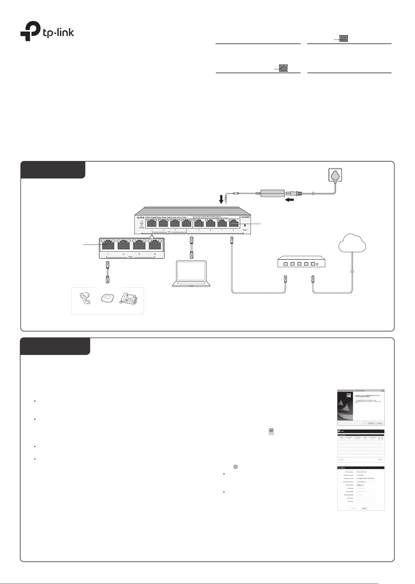
Connection
Power
On: Power on
O: Power o
Link/Act; Uplink 1, Uplink 2
Green On:
Running at 1000 Mbps, but no activity.
Green Flashing:
Running at 1000 Mbps and is transmitting or
receiving data.
Yellow On:
Running at 10/100 Mbps, but no activity.
Yellow Flashing:
Running at 10/100 Mbps and is transmitting
or receiving data.
O:
No device is linked to the corresponding port.
DC Power Adapter
PoE Status
On: Providing PoE power
Flashing: PoE fault
O: Not providing PoE power
PoE MAX
For TL-SG105PE:
On: 58 W≤Total power supply < 65 W
Flashing: Total power supply ≥ 65 W
O: Total power supply < 58 W
For TL-SG108PE:
On: 57 W≤Total power supply < 64 W
Flashing: Total power supply ≥ 64 W
O: Total power supply < 57 W
For TL-SG1210MPE:
On: 116 W≤Total power supply < 123 W
Flashing: Total power supply ≥ 123 W
O: Total power supply < 116 W
AC Power Cord
PoE Port (1–4)
PoE Devices
PC
Note:
IP Camera AP IP Phone
Conguration
The switch is plug and play. To congure the switch, you can use the Web-based
GUI or the conguration utility.
The utility is only supported on Windows now.
Using the Web-based GUI
1. Find out the IP address of the switch.
By default, the switch receives an IP addess from a DHCP server (typically a
router with DHCP function enabled) in your network. You can nd out this IP
address on the DHCP server.
If the switch cannot receive an IP address from a DHCP server, it uses the
static IP address of 192.168.0.1, with a subnet mask of 255.255.255.0.
2. Congure IP address on your PC to make sure the switch and PC are in the
same subnet.
If the switch uses an IP address assigned by a DHCP server, set your PC to
obtain an IP address automatically from the DHCP server.
If the switch uses 192.168.0.1 as the IP address, congure your PC’s IP
address as 192.168.0.x (”x” ranges from 2 to 254), and subnet mask as
255.255.255.0.
Launch a web browser on your PC, enter the IP address of the switch in the
3.
address bar and press Enter. Log in with admin as both user name and
password.
Now you can congure the switch using the Web-based GUI. For further
information, refer to the User Guide.
Go to https://www.tp-link.com/support, search the model number of your switch,
and you can nd this guide on the product Support web page.
Note:
1.
For certain devices, you may need to change the password the rst time
you log in, which will better protect your network and devices.
If the switch gets a new IP address from the DHCP server, your
2.
connection to the switch will be lost. Enter the new IP address in your
browser to access the switch again
.
Ethernet Ports (1-8)
Internet
Router
LAN Port
1. TL-SG1210MPE has two uplink ports, which typically connect to uplink devices like routers.
Uplink 1 is an SFP port and works with a 1000 Mbps SFP module. Uplink 2 is an RJ45 port.
2. PoE ports can also connect to non-PoE devices, but only transmit data.
3. For TL-SG105PE, maximum PoE power is 30 W for each PoE port and 65 W for all PoE ports in total.
For TL-SG108PE, maximum PoE power is 30 W for each PoE port and 64 W for all PoE ports in total.
For TL-SG1210MPE, maximum PoE power is 30 W for each PoE port and 123 W for all PoE ports in total.
WAN Port
Using the Conguration Utility
1. Go to https://www.tp-link.com/support and search the model number of your
switch. Download the Easy Smart Conguration Utility from the product
Support web page on your PC.
2. Decompress the downloaded le, run the
installation wizard and follow the prompts to install
the Easy Smart Conguration Utility.
Double click the icon on the desktop, and the
3.
utility Home page will display a list of TP-Link
switches on the local network.
Click to nd out IP parameters of the switch.
4.
If the switch uses an IP address assigned by a
DHCP server, set your PC to obtain an IP
address automatically from the DHCP server.
If the switch uses 192.168.0.1 as the IP address,
congure your PC’s IP address as 192.168.0.x
(”x” ranges from 2 to 254), and subnet mask as
255.255.255.0.
Double click the switch that you want to congure. Log in with admin as both
5.
user name and password.
Now you can congure the switch using the conguration utility. For further
information, refer to the Easy Smart Conguration Utility User Guide.
Go to https://www.tp-link.com/support, search the model number of your switch,
and you can nd this guide on the product Support web page.
Page 2
Specications
Frequently Asked Questions (FAQ)
General Specications
IEEE802.3i, IEEE802.3u, IEEE802.3ab,
Standard
Interface
Data Transfer Rate
Network Media (Cable)
Power Supply
Switching Capacity
MAC Address Table
Wall Mountable
Distance Between
Mounting Holes
IEEE802.3af, IEEE 802.3at, IEEE802.3x,
IEEE802.1p, IEEE802.1q
For TL-SG1210MPE: IEEE802.3z
For TL-SG105PE/TL-SG108PE:
5/8 10/100/1000 Mbps RJ45 Ports
Auto-Negotiation, Auto MDI/MDIX
PoE Ports: Port 1– Port 4
For TL-SG1210MPE:
9 10/100/1000 Mbps RJ45 Ports
Auto-Negotiation, Auto MDI/MDIX
1 1000 Mbps SFP port
PoE Ports: Port 1-Port 8
Ethernet: 10 Mbps (Half Duplex), 20 Mbps (Full Duplex)
Fast Ethernet: 100 Mbps (Half Duplex), 200 Mbps (Full
Duplex)
Gigabit Ethernet: 2000 Mbps (Full Duplex)
10Base-T: UTP category 3, 4, 5 cable (maximum 100 m)
EIA/TIA-568 100 Ω STP (maximum 100 m)
100Base-TX: UTP category 5, 5e cable (maximum 100
m) EIA/TIA-568 100 Ω STP (maximum 100 m)
1000Base-T: UTP category 5e cable or above (maximum
100 m) EIA/TIA-568 100 Ω STP (maximum 100 m)
1000BASE-SX/LX/LX10/BX10: MMF, SMF (Only for
TL-SG1210MPE)
External Power Adapter
Input: 100-240 V AC, 50/60 Hz
Output: 53.5 V DC/2.43 A (For TL-SG1210MPE)
53.5 V DC/1.31 A (For TL-SG105PE/TL-SG108PE)
TL-SG105PE: 10 Gbps
TL-SG108PE: 16 Gbps
TL-SG1210MPE: 20 Gbps
TL-SG105PE:
2K, automatically learning, automatically aging
TL-SG108PE/TL-SG1210MPE:
4K, automatically learning, automatically aging
Yes
TL-SG105PE: 39 mm
TL-SG108PE: 94 mm
TL-SG1210MPE: 150 mm
Q1. Why is the Power LED not lit?
The Power LED should be lit when the power system is working normally. If the Power
LED is not lit, please try the following:
A1: Make sure the power adapter is connected to the switch with power source
properly.
A2: Make sure the voltage of the power supply meets the requirements of the input
voltage of the switch.
A3: Make sure the power source is ON.
A4: On the LED On/O conguration page, check whether the LED status is on. By
default, the LED status is on.
Q2. Why is the Link/Act LED not lit while a device is connected to
the corresponding port?
Please try the following:
A1: Make sure that the cable connectors are rmly plugged into the switch and the
device.
A2: Make sure the connected device is turned on and works normally.
A3: The cable must be less than 100 meters long (328 feet). If Extend Mode is
enabled, it should be less than 250 meters (820 feet).
A4: On the LED On/O conguration page, check whether the LED status is on. By
default, the LED status is on.
Q3. Why is PoE/PoE+ Port not supplying power for PoE devices?
When the total power consumption of connected PoE devices exceeds the
maximum, the PoE port with a smaller port number has higher priority. The system will
cut o power to the ports with larger port numbers to ensure supplying to other ports.
Take TL-SG108PE as an example. Port 1, 2 and 4 are consuming 15.4 W respectively.
If an additional PoE device with 18 W is inserted to port 3, the system will cut o the
power of port 4 to compensate for the overload.
Environmental and Physical Specications
Certication
Operating Temperature
Storage Temperature
Operating Humidity
Storage Humidity
PoE Disclaimer
The speed of the ports in extend mode will downgrade to 10 Mbps. The actual transmission
distance may vary due to power consumption of PoE-powered devices or the cable quality and type.
PoE budget calculations are based on laboratory testing. Actual PoE power budget is not guaranteed
and will vary as a result of client limitations and environmental factors.
EU Declaration of Conformity
TP-Link hereby declares that the device is in compliance with the essential requirements and
other relevant provisions of directives 2014/30/EU, 2014/35/EU, 2009/125/EC, 2011/65/EU and
(EU)2015/863.
The original EU declaration of conformity may be found at https://www.tp-link.com/en/ce
FCC, CE, RoHS
0 ˚C to 40 ˚C (32 ˚F to 104 ˚F)
-40 ˚C to 70 ˚C (-40 ˚F to 158 ˚F)
10% to 90%RH non-condensing
5% to 90%RH non-condensing
To ask questions, find answers, and communicate with TP-Link
users or engineers, please visit https://community.tp-link.com
to join TP-Link Community.
For technical support, the user guide and other information,
please visit https://www.tp-link.com/support, or simply scan the
QR code.
If you have any suggestions or needs on the product guides,
welcome to email techwriter@tp-link.com.cn.
Some models featured in this guide may be unavailable in your country or region. For
local sales information, visit https://www.tp-link.com.
Safety Information
Keep the device away from water, re, humidity or hot environments.
Do not attempt to disassemble, repair, or modify the device. If you need service, please contact us.
Do not use damaged charger or USB cable to charge the device.
Do not use any other chargers than those recommended.
Adapter shall be installed near the equipment and shall be easily accessible.
Place the device with its bottom surface downward.
 Loading...