


TL-PA551
AV500+ Powerline Adapter with AC Pass Through
Rev: 1.0.0
1910010649

COPYRIGHT & TRADEMARKS
Specifications are subject to change without notice.  is a registered trademark of TP-LINK TECHNOLOGIES CO., LTD. Other brands and product names are trademarks or registered trademarks of their respective holders.
No part of the specifications may be reproduced in any form or by any means or used to make any derivative such as translation, transformation, or adaptation without permission from TP-LINK TECHNOLOGIES CO., LTD. Copyright © 2012 TP-LINK TECHNOLOGIES CO., LTD. All rights reserved.
http://www.tp-link.com
CE Mark Warning
This is a class B product. In a domestic environment, this product may cause radio interference, in which case the user may be required to take adequate measures.
Продукт сертифіковано згідно с правилами системи УкрСЕПРО на відповідність вимогам нормативних документів та вимогам, що передбачені чинними законодавчими актами України.

 TP-LINK TECHNOLOGIES CO., LTD
DECLARATION OF CONFORMITY
For the following equipment:
Product Description: AV500+ Powerline Adapter with AC Pass Through
Model No.: TL-PA551
Trademark: TP-LINK
We declare under our own responsibility that the above products satisfy all the technical regulations applicable to the product within the scope of Council Directives:
Directives 2004 / 108 / EC, Directives 2006 / 95 / EC, Directives 2011/65/EU
The above product is in conformity with the following standards or other normative documents
EN 55022:2010
EN 55024:2010
EN 61000-3-2:2006+A1:2009+A2:2009
EN 61000-3-3:2008
EN 50412-2-1:2005
EN 60950-1:2006+A11:2009+A1:2010
The product carries the CE Mark
Person is responsible for marking this declaration:
Yang Hongliang
Product Manager of International Business
Date of issue: 2012
TP-LINK TECHNOLOGIES CO., LTD.
Building 24 (floors 1, 3, 4, 5), and 28 (floors 1-4) Central Science and Technology Park, Shennan
Rd, Nanshan, Shenzhen, China
|
CONTENTS |
|
Package Contents......................................................................................... |
1 |
|
Conventions .................................................................................................. |
1 |
|
Chapter 1 Introduction ................................................................................. |
2 |
|
1.1 |
System Requirement.......................................................................... |
2 |
1.2 |
Important Safety Instructions ............................................................. |
2 |
1.3 |
LED Indicator ..................................................................................... |
3 |
1.4 |
Physical Interface............................................................................... |
4 |
Chapter 2 Connecting Mechanism .............................................................. |
6 |
|
2.1 |
Introduction ........................................................................................ |
6 |
2.2 |
Connection Instruction ....................................................................... |
6 |
2.3 |
Hardware Connection – Computer..................................................... |
7 |
2.4 |
Hardware Connection – Internet ........................................................ |
7 |
Chapter 3 Installing Management Utility..................................................... |
9 |
|
Chapter 4 Using the Management Utility .................................................. |
13 |
|
4.1 |
Status ............................................................................................... |
13 |
|
4.1.1 Set Local Device’s Network Name ......................................... |
14 |
4.2 |
Network............................................................................................ |
14 |
|
4.2.1 Rename the Remote Device/Enter Password........................ |
15 |
|
4.2.2 Add Device ............................................................................. |
16 |
4.3 Advanced ......................................................................................... |
17 |
|
4.4 |
System ............................................................................................. |
17 |
|
4.4.1 Upgrade Firmware ................................................................. |
18 |
|
4.4.2 Reset Device.......................................................................... |
19 |
|
4.4.3 Set All Devices’ Network Name.............................................. |
19 |
Chapter 5 Advanced Feature: How to Use the Pair Buttons ................... |
20 |
|
5.1 |
Pair (Secure with 128 bits-AES)....................................................... |
20 |
5.2 |
Set Up a Secured Powerline AV Network with the Pair Button ........ |
20 |
Appendix A: Troubleshooting.................................................................... |
22 |
|
Appendix B: Specifications........................................................................ |
23 |
|

TL-PA551 AV500+ Powerline Adapter with AC Pass Through
Package Contents
The AV500+ Powerline Adapter with AC Pass Through package contains the following items:
¾One AV500+ Powerline Adapter with AC Pass Through (There are two powerline adapters in Starter Kit)
¾One RJ-45 Cable (There are two RJ-45 Cables in Starter Kit)
¾One Quick Installation Guide
¾One Resource CD (Management Utility and User Guide)
) Note:
Make sure that the package contains the above items. If any of the above items are damaged or missing, please contact your dealer immediately.
Conventions
The powerline adapter or AV500+ Powerline Adapter with AC Pass Through mentioned in this guide stands for TL-PA551 AV500+ Powerline Adapter with AC Pass Through without any explanation.
1

TL-PA551 AV500+ Powerline Adapter with AC Pass Through
Chapter 1 Introduction
This device is an AV500+ Powerline Adapter with AC Pass Through which transforms your house’s existing electrical wiring into a ubiquitous networking infrastructure. Simply plug this AV500+ Powerline Adapter with AC Pass Through into an ordinary AC power outlet which will easily extend your Cable/xDSL broadband connection or existing Ethernet (LAN) network to any other electrical outlet in any room of a house without the need of any new cabling.
This Powerline Adapter supports up to 500Mbps data rate over the existing household power circuit. With data rates of 500Mbps, full multimedia application can easily be supported throughout the whole house in addition to Internet access. This Mini Powerline Adapter uses the existing power lines installed in a home as a path to transmit digital data, voice, audio and video between devices.
To ensure data communication’s security and multimedia applications, this Mini Powerline Adapter support built-in 128-bit AES encryption.
The new Powerline Adapter TL-PA551 from TP-LINK provides extra convenience and better performance for your home network with its integrated electrical socket and mains filer. The common problem of wasting an electrical outlet is solved and additional terminal devices or multiple sockets can be connected to the adapter just like to a normal wall socket. What’s more, the data transmission in the network can be significantly improved by the integrated mains filter.With minimum setup, you can install and use this Mini Powerline Adapter within minutes. The adapter adds two useful functions.
1 Existing connection with a new unassociated device added via the Pair Button.
2 Reset to default setting via the Management Utility.
1.1 System Requirement
a)At least two AC 100V ~ 240V (50~60Hz) power outlets with standard home power wiring
b)A computer with the following:
¾Operating System with TCP/IP installed
¾Pentium III compatible processor and above
¾Ethernet LAN card installed with TCP/IP protocol
¾64 MB RAM or more
¾50 MB of free disk space (Minimum)
¾CD-ROM Drive
1.2 Important Safety Instructions
1.Do not open this product or attempt to service it; it may expose you to dangerous high voltage or other risks.
2.Do not operate this product near water.
3.Do not place or operate this product near a radiator or a heat register.
4.Do not expose this product to dampness, dust or corrosive liquids.
5.Do not connect this product or disconnect it from a wall socket during a lightning or a thunderstorm
6.Do not block the ventilation slots of this product, for insufficient airflow may harm it.
7.Do not put anything on this product.
8.Plug this product directly into a wall socket (100V~240V, 50~60Hz). Do not use an extension cord
2

TL-PA551 AV500+ Powerline Adapter with AC Pass Through
between this product and the AC power source.
9.When plugging this product into a wall socket, make sure that the electrical socket is not damaged, and that there is no gas leakage.
10.Place the connecting cables properly so that people won’t stumble or walk on it.
11.This product should be operated from the type of power indicated on the marking label. If you are not sure of the type of power available, consult the qualified technician.
12.Unplug this product from the mains and refer the product to qualified service personnel for the following conditions:
¾If liquid has been spilled on the product
¾If the product has been exposed to rain or water
13.Unplug this product from the wall socket before cleaning. Use a damp cloth for cleaning. Do not use liquid cleaners or aerosol cleaners.
14.The specification of the fuse is T2.5AL250V. To avoid damage, please do not change the fuse.
15.The Operating temperature is 0 ~40 (32 ~104 ).
16.The Storage temperature is -40 ~70 (-40 ~158 ).
1.3 LED Indicator
The LED indicator displays information about the device’s status.
3
TL-PA551 AV500+ Powerline Adapter with AC Pass Through
|
Item |
|
Status |
|
Indication |
|
|
|
On |
|
The adapter is on. |
|
|
|
Blinking |
|
The adapter is in power-saving mode or in pairing |
|
Power LED |
|
|
procedure. |
|
|
|
|
|
||
|
|
|
Off |
The adapter is off. |
|
|
|
|
Green |
|
Data rate is more than or equal to 80Mbps. |
|
|
|
Orange |
|
Data rate is between 48Mbps and 80Mbps. |
|
Powerline LED |
|
Red |
|
Data rate is less than or equal to 48Mbps. |
|
|
|
Off |
|
The adapter isn’t connected to any powerline network or |
|
|
|
|
is in power-saving mode. |
|
|
|
|
|
|
|
|
|
|
On |
|
The Ethernet port is connected, but there is no data |
|
|
|
|
being transferred. |
|
|
|
|
|
|
|
|
Ethernet LED |
|
Blinking |
The Ethernet port is transferring data. |
|
|
|
|
Off |
The Ethernet port isn’t connected. |
|
) Note:
5 minutes after the device connected to the adapter is turned off, the adapter will automatically switch to the power-saving Mode.
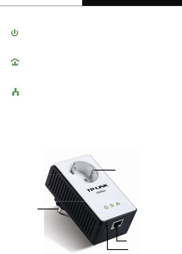
1.4 Physical Interface
There are four physical interfaces on this Mini Powerline Adapter.
Integrated Electrical Socket
Power Plug
Ethernet Port
Pair Button
4

TL-PA551 AV500+ Powerline Adapter with AC Pass Through
Interface |
Description |
|
Ethernet Port |
It is a 10/100Mbps Ethernet port on the AV adapter for connecting it |
|
to the PC or the broadband device with the network cable. |
||
|
||
Power Plug* |
A Power Plug connected to any 100V ~ 240V AC (50~60Hz) power |
|
socket |
||
|
||
|
Pair buttons are used to secure a powerline network. To secure |
|
|
your network, please follow the steps below. Firstly, plug in a new |
|
Pair Button |
adapter, and press its pair button for 1 second; then plug in another |
|
adapter and press its pair button for 1 second as well. The two |
||
|
buttons should be pressed within 2 minutes of each other. After |
|
|
that, wait about 60 seconds so that the two adapters can finish |
|
|
connecting. |
|
Integrated Electrical |
The integrated electrical socket allows additional devices or |
|
multiple sockets to be connected to the adapter just like to a normal |
||
Socket |
||
wall socket. No electrical socket is lost. |
||
|
* The provided power plug may differ from the picture due to different regional power specifications. Here we take the EU version as an example.
) Note:
1.If you press the pair button for more than 10 seconds, the powerline adapter will leave the network which it has joined and its new network name assumes a random value. The Power LED turns off when it disconnects from the powerline network.
2.For detailed information about the pair button, please refer to Charpter 5 Advanced Feature: How to Use the Pair Buttons.
5
 Loading...