


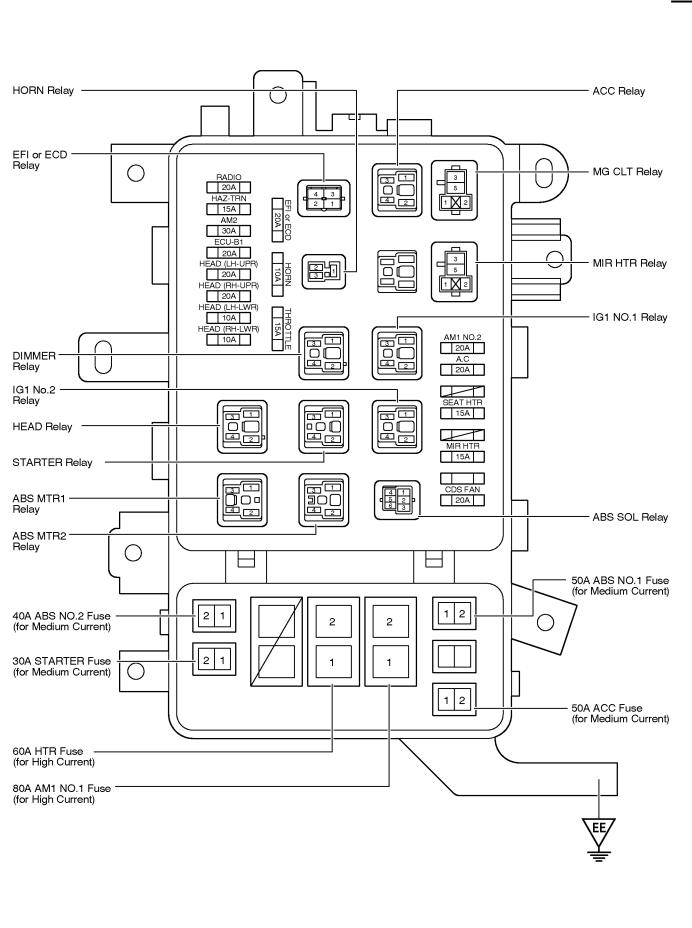
F RELAY LOCATIONS
[Engine Compartment]
[Instrument Panel]
20
F
[Body]
21
F RELAY LOCATIONS
: Engine Room J/B |
Engine Compartment Left (See Page 20) |
22
F
23
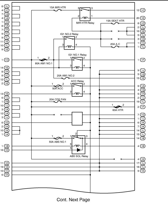
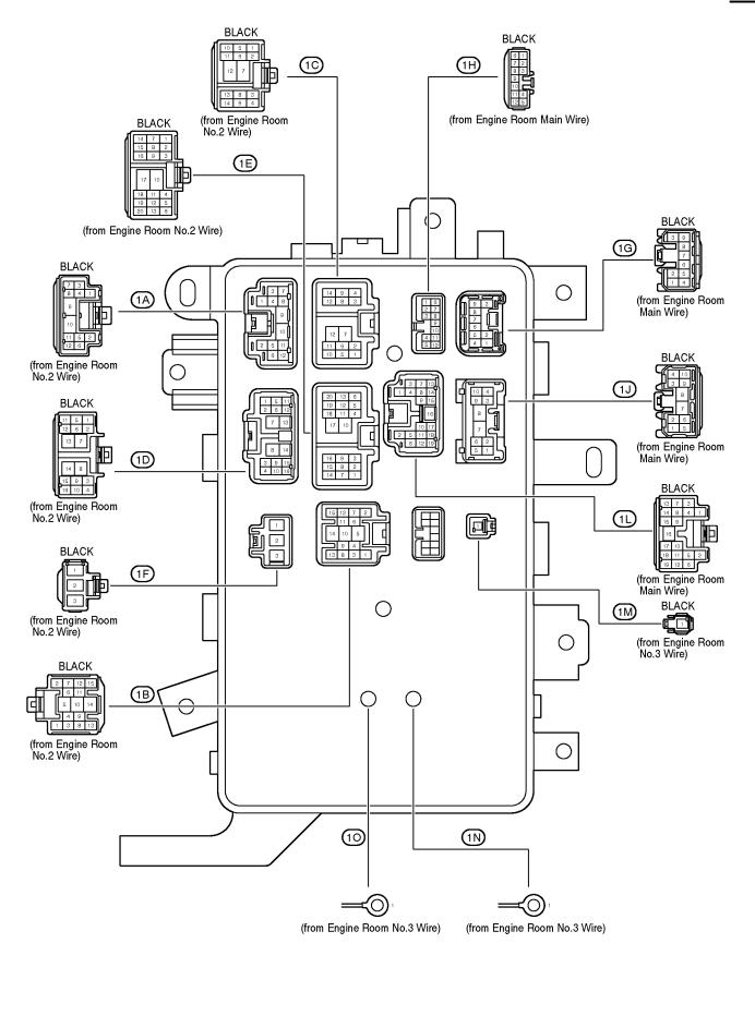
F RELAY LOCATIONS
[Engine Room J/B Inner Circuit]
24
F
25

F RELAY LOCATIONS
: Cowl Side J/B LH |
Left Kick Panel (See Page 20) |
26
F
27
F RELAY LOCATIONS
: Cowl Side J/B LH |
Left Kick Panel (See Page 20) |
28
F
[Cowl Side J/B LH Inner Circuit]
29
F RELAY LOCATIONS
[Cowl Side J/B LH Inner Circuit]
30
F
31
F RELAY LOCATIONS
: Cowl Side J/B RH |
Right Kick Penel (See Page 20) |
32
F
33
F RELAY LOCATIONS
[Cowl Side J/B RH Inner Circuit]
34
F
35
F RELAY LOCATIONS
Fusible Link Block |
Near the Battery (See Page 20) |
36

MEMO
37

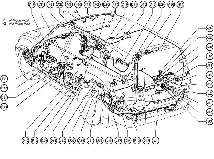
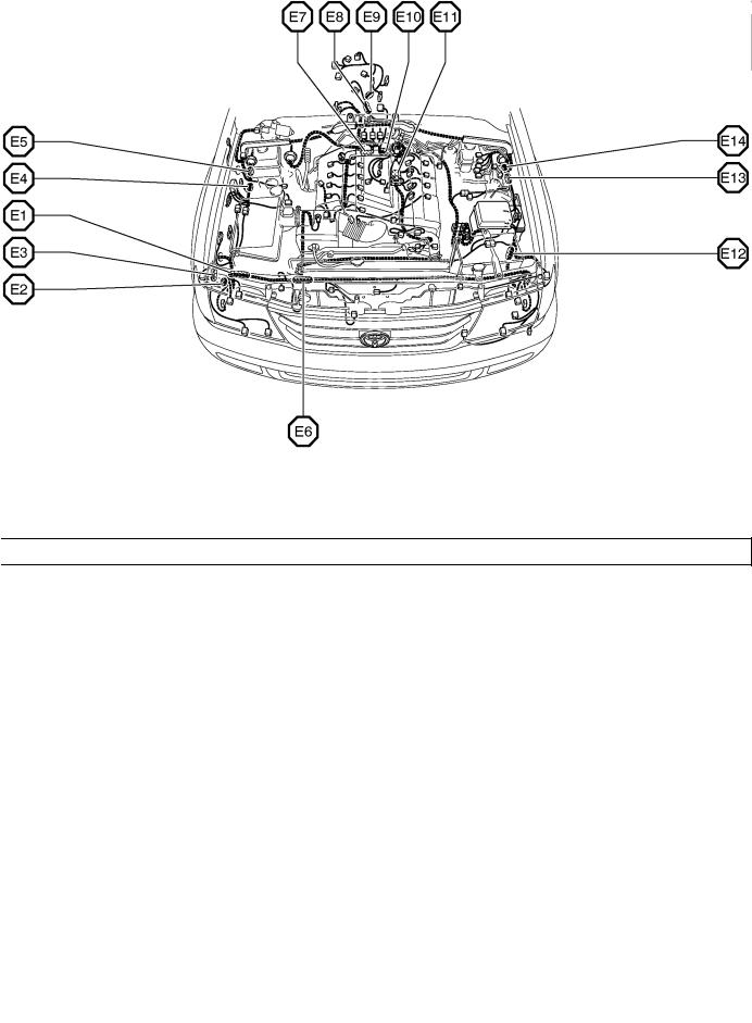
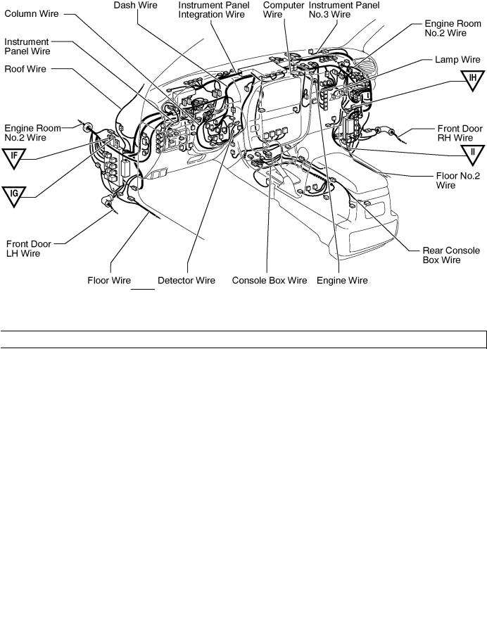
G ELECTRICAL WIRING ROUTING
Position of Parts in Engine Compartment
A |
1 |
A/C Ambient Temp. Sensor |
D |
1 |
Data Link Connector 1 |
A |
2 |
A/C Condenser Fan Motor |
D |
2 |
Daytime Running Light Relay No.3 |
A |
3 |
A/C Condenser Fan Relay |
D |
3 |
Daytime Running Light Relay No.3 |
A |
4 |
A/C Dual Pressure SW |
D |
4 |
Detection SW (Center Diff. Lock) |
A |
5 |
A/C Magnetic Clutch and Lock Sensor |
D |
5 |
Detection SW (Transfer L Position) |
A |
6 |
A/C Triple Pressure SW |
D |
6 |
Detection SW (Transfer Neutral Position) |
|
|
(A/C Dual and Single Pressure SW) |
|
|
|
A |
7 |
A/T Oil Temp. Sensor |
E |
1 |
Electronically Controlled Transmission Solenoid |
A |
8 |
ABS Actuator |
E |
2 |
Engine Coolant Temp. Sensor |
A |
9 |
ABS Actuator |
E |
3 |
Engine Hood Courtesy SW |
A10 |
ABS Actuator |
|
|
|
|
A 11 |
ABS Actuator |
F |
1 |
Front Fog Light LH |
|
A12 |
ABS Speed Sensor Front LH |
F |
2 |
Front Fog Light RH |
|
A13 |
ABS Speed Sensor Front RH |
F |
3 |
Front Turn Signal and Side Marker Light LH |
|
A14 |
Accel Position Sensor |
F |
4 |
Front Turn Signal and Side Marker Light RH |
|
A15 |
Airbag Sensor Front LH |
F |
5 |
Front Wiper Motor |
|
A16 |
Airbag Sensor Front RH |
F |
6 |
Fusible Link Block |
|
A17 |
Auto Antenna Motor |
|
|
|
|
A37 |
ABS & BA & TRAC & VSC Actuator |
G |
1 |
Generator |
|
A38 |
ABS & BA & TRAC & VSC Actuator |
G |
2 |
Generator |
|
A39 |
ABS & BA & TRAC & VSC Actuator |
|
|
|
|
A40 |
ABS & BA & TRAC & VSC Actuator |
|
|
|
|
C |
1 |
Camshaft Position Sensor |
|
|
|
C |
2 |
Center Diff. Lock Control Motor |
|
|
|
C |
3 |
Crankshaft Position Sensor |
|
|
|
38
G
Position of Parts in Engine Compartment
H |
1 |
Headlight LH (High) |
M 1 |
Mass Air Flow Meter |
|
H |
2 |
Headlight LH (Low) |
M 4 |
Master Cylinder Pressure Sensor |
|
H |
3 |
Headlight RH (High) |
N |
1 |
Noise Filter (Ignition) |
H |
4 |
Headlight RH (Low) |
|||
H |
5 |
Heated Oxygen Sensor (Bank 1 Sensor 1) |
O 1 |
O/D Direct Clutch Speed Sensor |
|
H |
6 |
Heated Oxygen Sensor (Bank 1 Sensor 2) |
|||
H |
7 |
Heated Oxygen Sensor (Bank 2 Sensor 1) |
O |
2 |
Oil Pressure Sender |
H |
8 |
Heated Oxygen Sensor (Bank 2 Sensor 2) |
P |
1 |
Park/Neutral Position SW,A/T Indicator Light SW and |
H |
9 |
Horn LH |
|||
H10 |
Horn RH |
|
|
Back-Up Light SW |
|
|
|
|
P |
2 |
Parking Light LH |
I |
1 |
Ignition Coil and Igniter No.1 |
P |
3 |
Parking Light RH |
I |
2 |
Ignition Coil and Igniter No.2 |
S |
1 |
Starter |
I |
3 |
Ignition Coil and Igniter No.3 |
|||
I |
4 |
Ignition Coil and Igniter No.4 |
S |
2 |
Starter |
I |
5 |
Ignition Coil and Igniter No.5 |
T |
1 |
Theft Deterrent Horn |
I |
6 |
Ignition Coil and Igniter No.6 |
|||
I |
7 |
Ignition Coil and Igniter No.7 |
T |
2 |
Throttle Control Motor |
I |
8 |
Ignition Coil and Igniter No.8 |
T |
3 |
Throttle Position Sensor |
I |
9 |
Injector No.1 |
V |
1 |
Vapor Pressure Sensor |
I 10 |
Injector No.2 |
||||
I |
11 |
Injector No.3 |
V |
2 |
Vehicle Speed Sensor (Combination Meter) |
I 12 |
Injector No.4 |
V |
3 |
Vehicle Speed Sensor |
|
I |
13 |
Injector No.5 |
|
|
(Electronically Controlled Transmission) |
I 14 |
Injector No.6 |
V |
4 |
VSV (EVAP) |
|
I 15 |
Injector No.7 |
V |
5 |
VSV (Vapor Pressure Sensor) |
|
I |
16 |
Injector No.8 |
W 1 |
Washer Motor |
|
|
|
|
|||
K |
1 |
Knock Sensor 1 |
W 2 |
Water Temp. Sender |
|
K |
2 |
Knock Sensor 2 |
|
|
|
39
G ELECTRICAL WIRING ROUTING
Position of Parts in Instrument Panel
A18 |
A/C Solar Sensor |
C14 |
Combination Meter |
|||
A19 |
A/C Thermistor |
C15 |
Combination Meter |
|||
A21 |
ABS ECU |
C16 |
Combination SW |
|||
A22 |
ABS ECU |
C17 |
Combination SW |
|||
A23 |
ABS ECU |
C18 |
Combination SW |
|||
A24 |
Air Inlet Control Servo Motor |
C19 |
Combination SW |
|||
A25 |
Air Mix Control Servo Motor |
D |
7 |
Data Link Connector 3 |
||
A26 |
Air Vent Mode Control Servo Motor |
|||||
A27 |
Airbag Squib (Front Passenger Airbag Assembly) |
D |
8 |
Daytime Running Light Relay (Main) |
||
A28 |
Airbag Squib (Steering Wheel Pad) |
D25 |
Deceleration Sensor |
|||
A29 |
Ashtray Illumination |
E |
4 |
Electronically Controlled Transmission Pattern |
||
A30 |
Auto Antenna Control Relay |
|||||
A31 |
Automatic Light Control Sensor |
|
|
Select SW |
||
A41 |
ABS & BA & TRAC & VSC ECU |
E |
5 |
Engine Control Module |
||
A42 |
ABS & BA & TRAC & VSC ECU |
E |
6 |
Engine Control Module |
||
A43 |
ABS & BA & TRAC & VSC ECU |
E |
7 |
Engine Control Module |
||
A44 |
ABS & BA & TRAC & VSC ECU |
E |
8 |
Engine Control Module |
||
B |
1 |
Blower Motor Controller |
E |
9 |
Engine Control Module |
|
F |
7 |
Fuel Control SW |
||||
C |
4 |
Center Airbag Sensor Assembly |
||||
G |
3 |
Glove Box Light |
||||
C |
5 |
Center Diff. Lock Control Relay |
||||
C 6 Center ECU |
I 17 |
Ignition Key Cylinder Light |
||||
C |
7 |
Center ECU |
||||
C |
8 |
Center ECU |
I 18 |
Ignition SW |
||
C |
9 |
Center ECU |
I 19 |
Instrument ECU |
||
C10 |
Cigarette Lighter |
I 20 |
Instrument ECU |
|||
C 11 |
Cigarette Lighter Illumination |
I 21 |
Instrument ECU |
|||
C12 |
Combination Meter |
|
|
|
||
C13 |
Combination Meter |
|
|
|
||
40
G
Position of Parts in Instrument Panel
J |
1 |
Junction Connector |
P |
4 |
Power Outlet (Front) |
|
J |
2 |
Junction Connector |
P |
5 |
Power Outlet (Rear Console Box) |
|
J |
3 |
Junction Connector |
P |
6 |
Power Quarter Window SW LH |
|
J |
4 |
Junction Connector |
P |
7 |
Power Quarter Window SW RH |
|
J |
7 |
Junction Connector |
|
|
|
|
J |
9 |
Junction Connector |
R |
1 |
Radio and Player |
|
J 10 |
Junction Connector |
R |
2 |
Rear Diff. Lock Control ECU |
||
J 11 |
Junction Connector |
R |
3 |
Rear Diff. Lock SW |
||
J 12 |
Junction Connector |
R |
4 |
Rear Heater SW |
||
J 13 |
Junction Connector |
R |
5 |
Remote Control Mirror SW |
||
J 14 |
Junction Connector |
R |
6 |
Rheostat |
||
J 15 |
Junction Connector |
R |
7 |
Room Temp. Sensor (Front) |
||
J 16 |
Junction Connector |
|
|
|
||
J 17 |
Junction Connector |
S |
3 |
Seat Heater SW (Driver's Seat) |
||
J 18 |
Junction Connector |
S |
4 |
Seat Heater SW (Front Passenger's Seat) |
||
J 19 |
Junction Connector |
S |
5 |
Stop Light SW |
||
J 20 |
Junction Connector |
|
|
|
||
J 21 |
Junction Connector |
T |
4 |
Telescopic Motor |
||
J 22 |
Junction Connector |
T |
5 |
Theft Deterrent ECU |
||
J 23 |
Junction Connector |
T |
6 |
Theft Deterrent ECU |
||
J 24 |
Junction Connector |
T |
7 |
Tilt and Telescopic ECU |
||
J 25 |
Junction Connector |
T |
8 |
Tilt and Telescopic ECU |
||
J 26 |
Junction Connector |
T |
9 |
Tilt Motor |
||
J 27 |
Junction Connector |
T 10 |
Transponder Key Amplifier |
|||
J 28 |
Junction Connector |
T 11 |
Turn Signal Flasher |
|||
J 29 |
Junction Connector |
|
|
|
||
J 30 |
Junction Connector |
U |
1 |
Unlock Warning SW |
||
J 42 |
Junction Connector |
|
|
|
||
J 43 |
Junction Connector |
V |
8 |
VSC Warning Buzzer |
||
J 44 |
Junction Connector |
W 3 |
Wireless Door Lock ECU |
|||
K |
3 |
Key Interlock Solenoid |
||||
Y |
1 |
Yaw Rate Sensor |
||||
O 3 |
O/D Main SW and Shift Lock Control ECU |
|||||
|
|
|
||||
41
G ELECTRICAL WIRING ROUTING
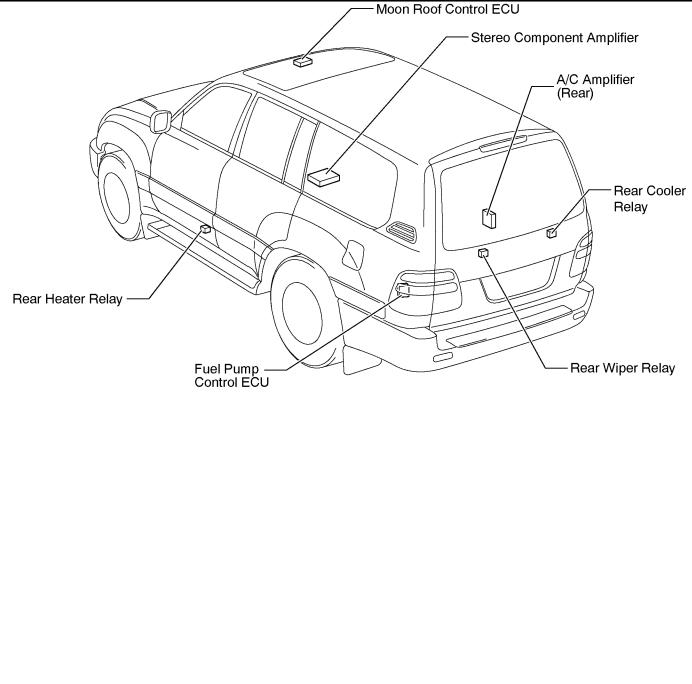
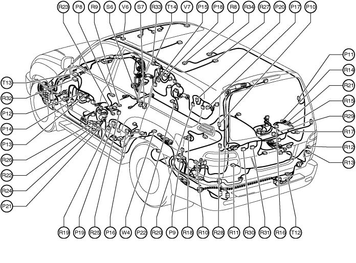
Position of Parts in Body
A32 |
A/C Amplifier (Rear) |
F |
8 |
Front Door Speaker LH |
||
A33 |
A/C Amplifier (Rear) |
F |
9 |
Front Door Speaker RH |
||
A34 |
A/C Amplifier (Rear) |
F 10 |
Front Interior Light and Rear Personal Light |
|||
A35 |
ABS Speed Sensor Rear LH |
F 11 |
Front Personal Light |
|||
A36 |
ABS Speed Sensor Rear RH |
F 12 |
Fuel Pump and Sender |
|||
B |
2 |
Back Door Courtesy SW |
F 13 |
Fuel Pump Control ECU |
||
H 11 |
High Mounted Stop Light |
|||||
B |
3 |
Back Door Key Lock and Unlock SW |
||||
B |
4 |
Back Door Lock Motor and |
J 31 |
Junction Connector |
||
|
|
Back DoorUnlock Detection SW |
||||
|
|
|
J 32 |
Junction Connector |
||
D |
9 |
Detection SW (Rear Diff. Lock) |
J 33 |
Junction Connector |
||
D10 |
Door Courtesy Light Front LH |
J 34 |
Junction Connector |
|||
D 11 |
Door Courtesy Light Front RH |
J 35 |
Junction Connector |
|||
D12 |
Door Courtesy Light Rear LH |
J 36 |
Junction Connector |
|||
D13 |
Door Courtesy Light Rear RH |
J 37 |
Junction Connector |
|||
D14 |
Door Courtesy SW Front LH |
J 38 |
Junction Connector |
|||
D15 |
Door Courtesy SW Front RH |
J 39 |
Junction Connector |
|||
D16 |
Door Courtesy SW Rear LH |
J 40 |
Junction Connector |
|||
D17 |
Door Courtesy SW Rear RH |
J 41 |
Junction Connector |
|||
D18 |
Door Key Lock and Unlock SW LH |
L |
1 |
License Plate Light LH |
||
D19 |
Door Key Lock and Unlock SW RH |
|||||
D20 |
Door Lock Control SW RH |
L |
2 |
License Plate Light RH |
||
D21 |
Door Lock Motor and Door Unlock Detection SW |
M 2 |
Moon Roof Control ECU |
|||
|
|
Front LH |
||||
D22 |
Door Lock Motor and Door Unlock Detection SW |
M 3 |
Moon Roof Control SW |
|||
|
|
Front RH |
|
|
|
|
D23 |
Door Lock Motor and Door Unlock Detection SW |
|
|
|
||
|
|
Rear LH |
|
|
|
|
D24 |
Door Lock Motor and Door Unlock Detection SW |
|
|
|
||
|
|
Rear RH |
|
|
|
|
42
G
Position of Parts in Body
P |
8 |
Parking Brake SW |
R20 |
Rear Door Speaker RH |
|
P |
9 |
Power Outlet (Luggage Compartment) |
R21 |
Rear Evaporator Temp. Sensor |
|
P10 |
Power Vent Window Motor LH |
R22 |
Rear Heater Blower Motor |
||
P 11 |
Power Vent Window Motor RH |
R23 |
Rear Heater Blower Resistor |
||
P12 |
Power Window Master SW |
R24 |
Rear Heater Fan Relay |
||
P13 |
Power Window Master SW |
R25 |
Rear Heater Power Transistor |
||
P14 |
Power Window Motor Front LH |
R26 |
Rear Inlet Air Temp. Sensor |
||
P15 |
Power Window Motor Front RH |
R27 |
Rear Interior Light |
||
P16 |
Power Window Motor Rear LH |
R28 |
Rear Window Defogger |
||
P17 |
Power Window Motor Rear RH |
R29 |
Rear Window Defogger |
||
P18 |
Power Window SW Front RH |
R30 |
Rear Wiper Motor |
||
P19 |
Power Window SW Rear LH |
R31 |
Rear Wiper Relay |
||
P20 |
Power Window SW Rear RH |
R32 |
Remote Control Mirror LH |
||
P21 |
Pretensioner LH |
R33 |
Remote Control Mirror RH |
||
P22 |
Pretensioner RH |
R34 |
Room Temp. Sensor (Rear) |
||
R |
8 |
Rear A/C Control SW |
S |
6 |
Stereo Component Amplifier |
R |
9 |
Rear Air Mix Control Servo Motor |
S |
7 |
Stereo Component Amplifier |
R10 |
Rear Combination Light LH |
|
|
|
|
R 11 |
Rear Combination Light LH |
T 12 |
Trailer Socket |
||
R12 |
Rear Combination Light RH |
T 13 |
Tweeter LH |
||
R13 |
Rear Combination Light RH |
T 14 |
Tweeter RH |
||
R14 |
Rear Cooler Blower Motor |
|
|
|
|
R15 |
Rear Cooler Magnetic Valve |
V |
6 |
Vanity Light LH |
|
R16 |
Rear Cooler Power Transistor |
V |
7 |
Vanity Light RH |
|
R17 |
Rear Cooler Relay |
|
|
|
|
R18 |
Rear Diff. Lock Motor |
W 4 |
Woofer (Speaker) |
||
R19 |
Rear Door Speaker LH |
|
|
|
|
43
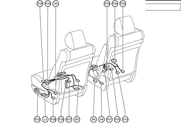
G ELECTRICAL WIRING ROUTING
Position of Parts in Seat
B |
5 |
Buckle SW LH |
P29 |
Power Seat Motor |
|
B |
6 |
Buckle SW RH |
|
|
(Driver's Seat Slide Control) |
|
|
|
P30 |
Power Seat Motor |
|
L |
3 |
Lumbar Support Control SW (Driver's Seat) |
|
|
(Front Passenger's Seat Front Vertical Control) |
|
|
|
P31 |
Power Seat Motor |
|
P23 |
Power Seat Control SW (Driver's Seat) |
|
|
(Front Passenger's Seat Rear Vertical Control) |
|
P24 |
Power Seat Control SW (Front Passenger's Seat) |
P32 |
Power Seat Motor |
||
P25 |
Power Seat Motor |
|
|
(Front Passenger's Seat Reclining Control) |
|
|
|
(Driver's Seat Front Vertical Control) |
P33 |
Power Seat Motor |
|
P26 |
Power Seat Motor |
|
|
(Front Passenger's Seat Slide Control) |
|
|
|
(Driver's Seat Lumbar Support Control) |
|
|
|
P27 |
Power Seat Motor |
S |
8 |
Seat Belt Warning Occupant Detection Sensor |
|
|
|
(Driver's Seat Rear Vertical Control) |
S |
9 |
Seat Heater (Driver's Seat) |
P28 |
Power Seat Motor |
S10 |
Seat Heater (Front Passenger's Seat) |
||
|
|
(Driver's Seat Reclining Control) |
|
|
|
44

MEMO
45
G ELECTRICAL WIRING ROUTING

 : Location of Connector Joining Wire Harness and Wire Harness
 : Location of Ground Points

 : Location of Splice Points
46
G
Connector Joining Wire Harness and Wire Harness
EA1 |
YELLOW |
EA2 |
GRAY |
EB1 |
GRAY |
1 |
2 |
1 |
1 |
2 |
3 |
3 |
2 |
1 |
1 |
2 |
3 |
4 |
4 |
3 |
2 |
1 |
2 |
|
4 |
5 |
6 |
6 |
5 |
4 |
|||||||||
|
|
|
5 |
6 |
7 |
8 |
8 |
7 |
6 |
5 |
||||||
|
|
|
|
|
|
|||||||||||
|
|
|
|
|
|
|
|
|
||||||||
|
|
|
|
|
|
|
|
|
9 |
10 11 12 |
12 11 10 |
9 |
||||
|
|
|
|
|
|
|
|
|
|
|
|
|
||||
EB2 |
BLACK |
EB3 |
DARK GRAY |
1 |
|
3 |
3 |
1 |
1 |
2 |
3 |
3 |
2 |
1 |
2 |
4 |
6 |
5 |
5 |
6 |
4 |
||||
4 |
5 |
6 |
6 |
2 |
7 |
8 |
8 |
7 |
||
7 |
8 |
4 |
|
|
||||||
|
|
5 |
9 |
|
11 |
11 |
|
9 |
||
9 |
10 |
11 |
8 |
7 |
10 |
10 |
||||
|
|
|
11 |
10 |
|
|
|
|
|
|
|
|
|
9 |
|
|
|
|
|
|
|
EC1 |
BLACK |
ED1 |
GRAY |
EE1 |
BLACK |
|
|
|
|
|
|
|
|
|
|
|
|
|
|
|
|
|
|
1 |
|
1 |
1 |
1 |
|
2 |
1 |
|
|
1 |
2 |
|||||
|
|
|
||||||
|
|
|
|
|
|
3 |
||
2 |
3 |
3 |
|
2 |
|
3 |
|
|
|
|
|
|
EF1 |
YELLOW |
|
|
|
|
EG1 |
|
|
|
|
||||
|
|
|
|
|
|
|
|
|
|
|
|
|
|
|
|
|
|
|
|
|
|
|
|
|
|
|
|
|
|
|
|
|
|
|
|
|
|
|
|
|
|
|
|
|
1 |
2 |
2 |
1 |
|
|
|
|
|
|||
|
|
|
1 |
1 |
|
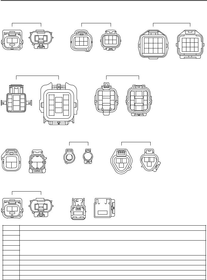
Code |
Joining Wire Harness and Wire Harness (Connector Location) |
||||
EA1 |
Engine Room Main Wire and Engine Room No.2 Wire (Engine Compartment Right) |
||||
EA2 |
|||||
|
|
|
|||
EB1 |
|
|
|
||
EB2 |
Engine Wire and Transmission Wire (On the Transmission) |
||||
EB3 |
|
|
|
||
EC1 |
Engine No.2 Wire and Engine Wire (On the Transmission) |
|
|||
ED1 |
Engine No.2 Wire and Engine Room No.2 Wire (Near the Engine Room J/B) |
||||
EE1 |
Engine Room Main Wire and Alternator Wire (Near the Battery) |
||||
EF1 |
Engine Room No.2 Wire and Engine Room Main Wire (Under the Engine Room J/B) |
||||
EG1 |
Engine Room No.2 Wire and Engine Room No.3 Wire (Under the Engine Room J/B) |
||||
47
G ELECTRICAL WIRING ROUTING


 : Location of Connector Joining Wire Harness and Wire Harness

 : Location of Ground Points
48
G
Connector Joining Wire Harness and Wire Harness
|
IA1 |
|
|
IB1 |
YELLOW |
IC1 |
ORANGE |
|
|
|
|
|
|
|
|
|
|
|
|
|
|
|
|
1 2 |
3 |
3 |
2 1 |
|
2 |
1 |
|
|
|
|
|
|
|
|
|
|
|
|
|
|
|
|
|
|
|
|
|
|
|
|
|
||||
4 5 6 7 8 |
8 7 6 5 4 |
1 |
2 |
1 |
2 |
|
|
3 |
4 |
4 |
3 |
|
|
2 |
1 |
||
|
|
|
|
|
|
|
|
|
|
|
|
|
|
||||
|
|
|
|
|
|
5 |
6 |
7 |
8 |
9 |
10 |
10 |
9 |
8 |
7 |
6 |
5 |
|
|
|
|
|
|
|
|
|
|
|
|
||||||
|
|
|
|
|
|
11 |
12 |
13 |
14 |
15 |
16 |
16 |
15 |
14 |
13 |
12 |
11 |
|
|
|
|
|
|
|
|
|
|
|
|
||||||
ID1 |
|
ID2 |
YELLOW |
IE1 |
|
|
|
|
|
|
4 |
3 |
|
|
2 |
1 |
2 |
2 |
1 |
1 |
2 |
2 1 |
1 |
2 |
|
|
3 |
4 |
|
|
1 |
|
|
|
|
|
|
|||
|
|
|
|
|
|
|
|
|
|
|
|
|
|
||||
5 |
6 |
7 |
8 |
9 |
10 |
10 9 |
8 |
7 |
6 |
5 |
|
|
|
|
|
|
|
|
|
|
|
|
|
|
|
|
|
|
|
||||||
11 12 |
|
|
13 14 |
14 13 |
|
|
12 11 |
|
|
|
|
|
|
||||
|
|
|
|
|
|
|
|
|
|
|
|
|
|
||||
15 16 |
17 |
18 19 20 |
20 19 18 |
17 16 15 |
|
|
|
|
|
|
|||||||
|
|
|
|
|
|
|
|
|
|
|
|
||||||
IF1
9 |
8 |
7 |
6 |
5 |
4 |
3 |
2 |
1 |
1 2 3 4 5 6 7 8 9 |
|
|
|
|
|
|
|
|
18 17 16 15 14 13 12 11 10 |
||||||||
101112131415161718 |
|
|
|
|
|
|
|
|
IF2 GRAY
|
11 10 9 |
8 |
7 |
6 |
5 |
4 |
3 |
2 |
1 |
|
1 2 3 4 5 6 7 8 9 1011 |
|
|
|
|
|
|
|
|
||
|
22 21 20 19 18 17 16 15 14 13 12 |
|||||||||
1213141516171819202122 |
|
|
|
|
|
|
|
|
||
|
|
|||||||||
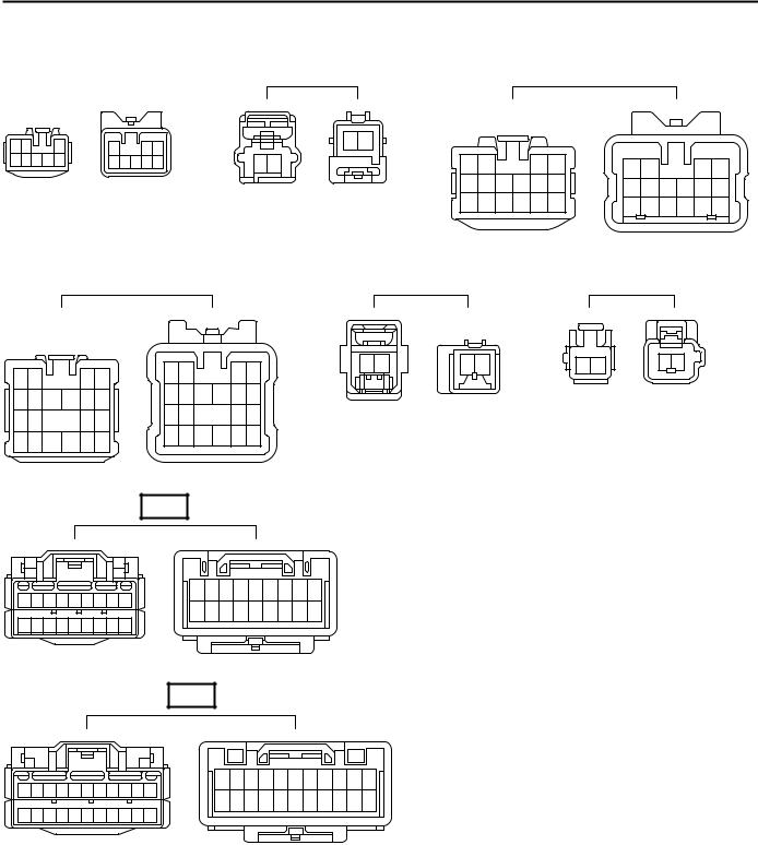
Code |
Joining Wire Harness and Wire Harness (Connector Location) |
|||||||||
|
|
|
||||||||
IA1 |
Floor Wire and Engine Room No.2 Wire (Left Kick Panel) |
|
||||||||
|
|
|
||||||||
IB1 |
Engine Room No.2 Wire and Dash Wire (Left Kick Panel) |
|
||||||||
|
|
|
|
|||||||
IC1 |
Front Door LH Wire and Dash Wire (Left Kick Panel) |
|
|
|||||||
|
|
|
|
|
|
|
|
|
|
|
ID1 |
Dash Wire and Floor Wire (Left Kick Panel) |
|
|
|
|
|
||||
|
|
|
|
|
|
|||||
ID2 |
|
|
|
|
|
|||||
|
|
|
|
|
|
|
|
|
||
|
|
|
|
|
|
|
||||
IE1 |
Dash Wire and Roof Wire (Left Kick Panel) |
|
|
|
|
|
||||
|
|
|
|
|
|
|
|
|
|
|
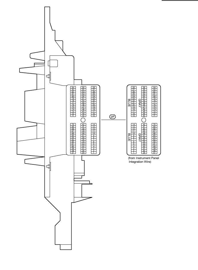
IF1 |
Instrument Panel Integration Wire and Instrument Panel Wire (Left Side of Instrument Panel) |
|||||||||
|
||||||||||
IF2 |
||||||||||
|
|
|
|
|
|
|
|
|
||
|
|
|
|
|
|
|
|
|
|
|
49
 Loading...