


Diesel Injection Pump
SERVICE MANUAL
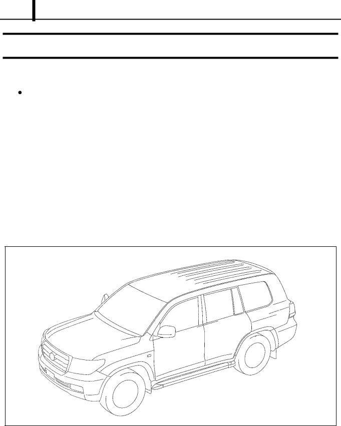
TOYOTA LAND CRUISER (200 SERIES)
1VD-FTV ENGINE
COMMON RAIL SYSTEM (CRS)
OPERATION
September, 2007
00400609E
© 2007 DENSO CORPORATION
All Rrights Reserved. This book may not be reproduced or copied, in whole or in part, without the written permission of the publisher.
Table of Contents
Operation Section
1. APPLICABLE VEHICLE AND PRODUCT INFORMATION
1.1 Introduction . . . . . . . . . . . . . . . . . . . . . . . . . . . . . . . . . . . . . . . . . . . . . . . . . . . . . . . . . . . . . . . . . . . . . . . . . . . . 1-1
1.2 Applicable Vehicle . . . . . . . . . . . . . . . . . . . . . . . . . . . . . . . . . . . . . . . . . . . . . . . . . . . . . . . . . . . . . . . . . . . . . . . 1-1
1.3 Layout of Main Components . . . . . . . . . . . . . . . . . . . . . . . . . . . . . . . . . . . . . . . . . . . . . . . . . . . . . . . . . . . . . . . 1-2
1.4 Applicable Product List . . . . . . . . . . . . . . . . . . . . . . . . . . . . . . . . . . . . . . . . . . . . . . . . . . . . . . . . . . . . . . . . . . . 1-3
1.5 CRS Construction . . . . . . . . . . . . . . . . . . . . . . . . . . . . . . . . . . . . . . . . . . . . . . . . . . . . . . . . . . . . . . . . . . . . . . . 1-4
2. SUPPLY PUMP
2.1 Outline . . . . . . . . . . . . . . . . . . . . . . . . . . . . . . . . . . . . . . . . . . . . . . . . . . . . . . . . . . . . . . . . . . . . . . . . . . . . . . . . 1-5
2.2 Suction Control Valve (SCV) . . . . . . . . . . . . . . . . . . . . . . . . . . . . . . . . . . . . . . . . . . . . . . . . . . . . . . . . . . . . . . . 1-6
3. RAIL
3.1 Outline . . . . . . . . . . . . . . . . . . . . . . . . . . . . . . . . . . . . . . . . . . . . . . . . . . . . . . . . . . . . . . . . . . . . . . . . . . . . . . . . 1-7
4. INJECTOR
4.1 Outline . . . . . . . . . . . . . . . . . . . . . . . . . . . . . . . . . . . . . . . . . . . . . . . . . . . . . . . . . . . . . . . . . . . . . . . . . . . . . . . . 1-8
5. CONTROL SYSTEM
5.1 |
Control System Diagram . . . . . . . . . . . . . . . . . . . . . . . . . . . . . . . . . . . . . . . . . . . . . . . . . . . . . . . . . . . . . . . . . |
. 1-9 |
5.2 |
Engine Electronic Control Unit (ECU) . . . . . . . . . . . . . . . . . . . . . . . . . . . . . . . . . . . . . . . . . . . . . . . . . . . . . . . |
1-10 |
5.3 |
EDU . . . . . . . . . . . . . . . . . . . . . . . . . . . . . . . . . . . . . . . . . . . . . . . . . . . . . . . . . . . . . . . . . . . . . . . . . . . . . . . . . |
1-10 |
5.4 |
Sensors . . . . . . . . . . . . . . . . . . . . . . . . . . . . . . . . . . . . . . . . . . . . . . . . . . . . . . . . . . . . . . . . . . . . . . . . . . . . . . |
1-11 |
5.5 |
Exhaust Gas Recirculation (EGR) Valve . . . . . . . . . . . . . . . . . . . . . . . . . . . . . . . . . . . . . . . . . . . . . . . . . . . . . |
1-13 |
6. FUEL INJECTION CONTROL
6.1 |
Outline . . . . . . . . . . . . . . . . . . . . . . . . . . . . . . . . . . . . . . . . . . . . . . . . . . . . . . . . . . . . . . . . . . . . . . . . . . . . . . . |
1-14 |
6.2 |
Injection Pattern. . . . . . . . . . . . . . . . . . . . . . . . . . . . . . . . . . . . . . . . . . . . . . . . . . . . . . . . . . . . . . . . . . . . . . . . |
1-14 |
7. ENGINE ECU DIAGNOSTIC TROUBLE CODES (DTC)
7.1 DTC Table . . . . . . . . . . . . . . . . . . . . . . . . . . . . . . . . . . . . . . . . . . . . . . . . . . . . . . . . . . . . . . . . . . . . . . . . . . . . 1-15
8. ATTACHED MATERIALS
8.1 Engine ECU External Wiring Diagram. . . . . . . . . . . . . . . . . . . . . . . . . . . . . . . . . . . . . . . . . . . . . . . . . . . . . . . 1-18
8.2 Connector Terminal Layout . . . . . . . . . . . . . . . . . . . . . . . . . . . . . . . . . . . . . . . . . . . . . . . . . . . . . . . . . . . . . . . 1-20
Operation Section
1 1
1. APPLICABLE VEHICLE AND PRODUCT INFORMATION
1.1 Introduction
As a result of a model change, TOYOTA's first V-8 engine, the "1VD-FTV" has been installed in the TOYOTA LAND CRUISER (200 series). This manual describes the Common Rail System (CRS) installed on the LAND CRUISER (200 series) 1VD-FTV engine.
For common information to all CRSs, refer to the previously published CRS general addition manual (Doc ID: 00400076E).
[Items common to all CRSs: CRS development process, system control, construction and operation of main components (supply pump, rail, injectors), sensors and actuators.]
1.2 Applicable Vehicle
Vehicle Name |
Vehicle |
Engine |
Engine |
Destination |
Release Date |
|
Model |
Model |
Displacement |
||||
|
|
|
||||
|
|
|
|
|
|
|
LAND CRUISER |
VDJ200 |
1VD-FTV |
4.5L |
Europe, Australia, Russia, Mid- |
August. 2007 |
|
(200 Series) |
dle East, General |
|||||
|
|
|
|
|||
|
|
|
|
|
|
Operation Section
1 2
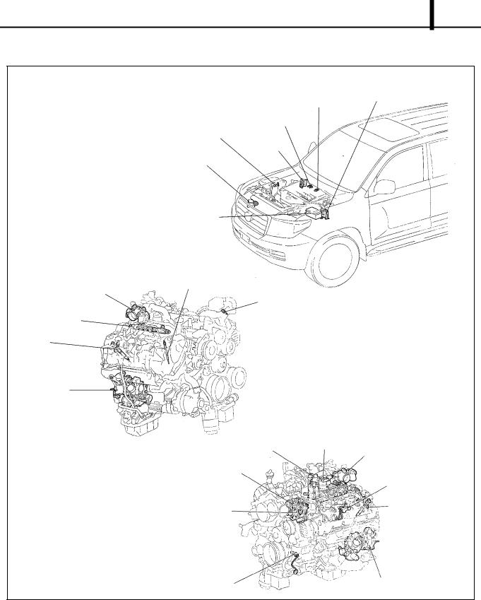
1.3 Layout of Main Components
|
|
|
|
|
|
||
|
|||
|
|
||
|
|
|
|
|
|
|
|
|
|
|
|
|
|
|
|
|
|
|
|
|
|
||
|

Operation Section
1 3
1.4 Applicable Product List
Parts Name |
DENSO Part Number |
Manufacturer Part Number |
Remarks |
|
|
|
|
|
|
Supply Pump |
294050-023# |
22100-51030 |
HP4 |
|
|
|
|||
294050-024# |
22100-51040 |
|||
|
|
|||
|
|
|
|
|
Injector |
095000-673# |
23670-51020 |
8 injectors |
|
|
|
|
|
|
Rail |
HU095440-100# |
23810-0W010 |
RH |
|
|
|
|
||
HU095440-104# |
23820-0W010 |
LH |
||
|
||||
|
|
|
|
|
|
275900-002# |
89661-60F60 |
AT, Europe |
|
|
|
|
|
|
|
275900-003# |
89661-60F70 |
AT, Australia, Russia |
|
|
|
|
|
|
|
275900-004# |
89661-60F80 |
AT, General, Middle East |
|
|
|
|
|
|
Engine ECU |
275900-005# |
89661-60F90 |
AT, General |
|
|
|
|
||
275900-006# |
89661-60G00 |
AT, EGR, General |
||
|
||||
|
|
|
|
|
|
275900-007# |
89661-60G10 |
AT, General, Middle East |
|
|
|
|
|
|
|
275900-008# |
89661-60G20 |
MT, General |
|
|
|
|
|
|
|
275900-009# |
89661-60G30 |
MT, EGR, General |
|
|
|
|
|
|
EDU |
101310-578# |
89870-60070 |
2 EDUs |
|
|
|
|
|
|
Crankshaft Position Sensor |
029600-074# |
90919-05029 |
|
|
|
|
|
|
|
Cylinder Recognition Sensor |
029600-149# |
90919-05072 |
|
|
|
|
|
|
|
Coolant Temperature Sensor |
071560-005# |
89422-16010 |
|
|
|
|
|
|
|
Accelerator Pedal Module |
198800-359# |
78120-60410 |
|
|
|
|
|
|
|
EGR Valve No.1 |
135000-727# |
23620-51010 |
RH |
|
|
|
|
|
|
EGR Valve No.2 |
135000-728# |
25630-51010 |
LH |
|
|
|
|
|
Operation Section
1 4
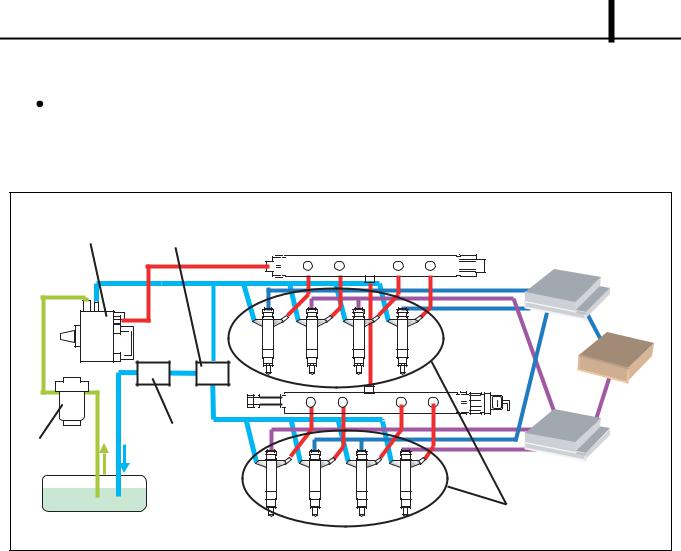
1.5 CRS Construction
The illustration below is an outline of the CRS. The primary feature of this system is the use of two rails and two EDUs in order to comply with the V-8 engine. When looking into the engine compartment from the driver's seat, the two rails are positioned above the right and left banks (hereafter: right bank rail = "rail RH", left bank rail = "rail LH"). EDU No.1 and No.2 each control four injectors.
|
|
|
|
|
|
|
|
|
|
|
|
|
|
|
|
|
|
|
||
|
|
|
|
|
|
|
|
|
|
|
|
|
|
|
|
|
|
|
|
|
|
|
|
|
|
|
|
|
|
|
|
|
|
|
|
|
|
|
|
|
|
|
|
|
|
|
|
|
|
|
|
|
|
|
|
|
|
|
|
|
|
|
|
|
|
|
|
|
|
|
|
|
|
|
|
|
|
|
|
|
|
|
|
|
|
|
|
|
|
|
Operation Section
1 5
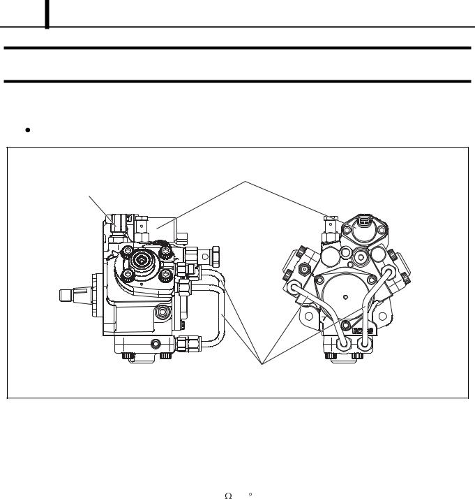
2. SUPPLY PUMP
2.1 Outline
The CRS used in the TOYOTA LANDCRUISER (200 Series) is equipped with an HP4 supply pump.
Supply Pump Specifications
|
Item |
Content |
|
|
|
Plunger Diameter |
Ø8.5 × 3 |
|
|
|
|
Cam Lift |
|
8.8 mm |
|
|
|
Rotation |
|
Clockwise viewed from drive side |
|
|
|
|
Terminal Resistance |
2.10 ± 0.15 (20 C) |
SCV |
(Rated Voltage) |
12 V |
|
Control Type |
Normally closed |
|
|
|

Operation Section
1 6
2.2 Suction Control Valve (SCV)
A conventional normally closed type SCV has been adopted for use with the 1VD-FTV engine.
|
|
|
Operation Concept Diagram
|
|
|
|
Operation |
|
|
|
|
|
|
|
|
|
|
|
 Loading...