


 Loading...
Toshiba Personal Computer
Satellite T110/Satellite ProT110/PORTEGE T110
Maintenance Manual
TOSHIBA CORPORATION
File Number 960-Q08
Satellite T110 / Satellite Pro T110 / PORTEGE T110 Maintenance Manual (960-Q08)

Copyright
© 2009 by Toshiba Corporation. All rights reserved. Under the copyright laws, this manual cannot be reproduced in any form without the prior written permission of Toshiba. No patent liability is assumed with respect to the use of the information contained herein.
Toshiba Personal Computer Satellite T110, Satellite Pro T110, PORTEGE T110 Maintenance Manual
First edition Sept. 2009
Disclaimer
The information presented in this manual has been reviewed and validated for accuracy. The included set of instructions and descriptions are accurate for the Satellite T110, Satellite Pro T110, and PORTEGE T110 Series at the time of this manual's production. However, succeeding computers and manuals are subject to change without notice. Therefore, Toshiba assumes no liability for damages incurred directly or indirectly from errors, omissions, or discrepancies between any succeeding product and this manual.
Trademarks
Intel, Intel SpeedStep, Intel Core, Pentium and Celeron are trademarks or registered trademarks of Intel Corporation or its subsidiaries in the United States and other countries/regions.
Windows and Microsoft are registered trademarks of Microsoft Corporation.
Other trademarks and registered trademarks not listed above may be used in this manual.
Satellite T110 / Satellite Pro T110 / PORTEGE T110 Maintenance Manual (960-Q08)

Preface
This maintenance manual describes how to perform hardware service maintenance for the Toshiba Personal Computer Satellite T110, Satellite Pro T110, and PORTEGE T110 Series.
The procedures described in this manual are intended to help service technicians isolate faulty Field Replaceable Units (FRUs) and replace them in the field.
SAFETY PRECAUTIONS
Four types of messages are used in this manual to bring important information to your attention. Each of these messages will be italicized and identified as shown below.
DANGER: “Danger” indicates the existence of a hazard that could result in death or serious bodily injury, if the safety instruction is not observed.
WARNING: “Warning” indicates the existence of a hazard that could result in bodily injury, if the safety instruction is not observed.
CAUTION: “Caution” indicates the existence of a hazard that could result in property damage, if the safety instruction is not observed.
NOTE: “Note” contains general information that relates to your safe maintenance service.
Improper repair of the computer may result in safety hazards. Toshiba requires service technicians and authorized dealers or service providers to ensure the following safety precautions are adhered to strictly.
Be sure to fasten screws securely with the right screwdriver. If a screw is not fully fastened, it could come loose, creating a danger of a short circuit, which could cause overheating, smoke or fire.
If you replace the battery pack or RTC battery, be sure to use only the same model battery or an equivalent battery recommended by Toshiba. Installation of the wrong battery can cause the battery to explode.
Satellite T110 / Satellite Pro T110 / PORTEGE T110 Maintenance Manual (960-Q08)

The manual is divided into the following parts:
Chapter 1 Hardware Overview describes the Satellite T110, Satellite Pro T110, PORTEGE T110 system unit and each FRU.
Chapter 2 Troubleshooting Procedures explains how to diagnose and resolve FRU problems.
Chapter 3 Test and Diagnostics describes how to perform test and diagnostic operations for maintenance service.
Chapter 4 Replacement Procedures describes the removal and replacement of the FRUs.
Appendices The appendices describe the following:
Handling the LCD Module
Board layout
Pin assignments
Keyboard scan/character codes
Key layout
Wiring diagrams
Satellite T110 / Satellite Pro T110 / PORTEGE T110 Maintenance Manual (960-Q08)

Conventions
This manual uses the following formats to describe, identify, and highlight terms and operating procedures.
Acronyms
On the first appearance and whenever necessary for clarification acronyms are enclosed in parentheses following their definition. For example:
Read Only Memory (ROM)
Keys
Keys are used in the text to describe many operations. The key top symbol as it appears on the keyboard is printed in boldface type.
Key operation
Some operations require you to simultaneously use two or more keys. We identify such operations by the key top symbols separated by a plus (+) sign. For example, Ctrl + Pause (Break) means you must hold down Ctrl and at the same time press Pause (Break). If three keys are used, hold down the first two and at the same time press the third.
User input
Text that you are instructed to type in is shown in the boldface type below:
DISKCOPY A: B:
The display
Text generated by the computer that appears on its display is presented in the typeface below:
Format complete
System transferred
Satellite T110 / Satellite Pro T110 / PORTEGE T110 Maintenance Manual (960-Q08)

Table of Contents |
|
|
Chapter 1 Hardware Overview |
|
|
1.1 |
Features.......................................................................................................................... |
1 |
1.2 |
System Block Diagram .................................................................................................. |
6 |
1.3 |
2.5-inch Hard Disk Drive............................................................................................... |
9 |
1.4 |
Keyboard...................................................................................................................... |
12 |
1.5 |
TFT Color Display....................................................................................................... |
13 |
|
1.5.1 LCD Module with CCFL Backlight ............................................................. |
13 |
1.6 |
Power Rails .................................................................................................................. |
14 |
1.7 |
Batteries ....................................................................................................................... |
15 |
|
1.7.1 Main Battery ................................................................................................. |
15 |
|
1.7.2 Battery Charging Control.............................................................................. |
15 |
|
1.7.3 RTC battery................................................................................................... |
17 |
1.8 |
AC Adapter .................................................................................................................. |
18 |
Satellite T110 / Satellite Pro T110 / PORTEGE T110 Maintenance Manual (960-Q08)

Chapter 2 Troubleshooting Procedures |
|
|
2.1 |
Troubleshooting ............................................................................................................ |
1 |
2.2 |
Troubleshooting Flowchart........................................................................................... |
2 |
2.3 |
Power Supply Troubleshooting..................................................................................... |
6 |
|
Procedure 1 Power Status Check .................................................................................. |
6 |
|
Procedure 2 Connection Check..................................................................................... |
8 |
|
Procedure 3 Charging Check ........................................................................................ |
8 |
|
Procedure 4 Replacement Check ................................................................................ |
10 |
2.4 |
System Board Troubleshooting................................................................................... |
11 |
|
Procedure 1 Message Check ....................................................................................... |
12 |
|
Procedure 2 Debugging Port Check............................................................................ |
13 |
|
Procedure 3Replacement Check ................................................................................. |
13 |
2.5 |
Hard Disk Drive Troubleshooting .............................................................................. |
14 |
|
Procedure 1 Partition Check ....................................................................................... |
14 |
|
Procedure 2 Message Check ....................................................................................... |
15 |
|
Procedure 3 Diagnostic Test Program Execution Check ............................................ |
16 |
|
Procedure 4 Connector Check and Replacement Check............................................. |
17 |
2.6 |
Keyboard Troubleshooting ......................................................................................... |
18 |
|
Procedure 1 Diagnostic Test Program Execution Check ............................................ |
18 |
|
Procedure 2 Connector Check and Replacement Check............................................. |
19 |
2.7 |
Touch pad Troubleshooting ........................................................................................ |
20 |
|
Procedure 1 Diagnostic Test Program Execution Check ............................................ |
20 |
|
Procedure 2 Connector Check and Replacement Check............................................. |
21 |
2.8 |
Display Troubleshooting............................................................................................. |
22 |
|
Procedure 1 External Monitor Check.......................................................................... |
22 |
|
Procedure 2 Diagnostic Test Program Execution Check ............................................ |
22 |
|
Procedure 3 Connector and Cable Check ................................................................... |
23 |
|
Procedure 4 Replacement Check ................................................................................ |
24 |
2.9 |
LAN Troubleshooting................................................................................................. |
25 |
|
Procedure 1 Diagnostic Test Program Execution Check ............................................ |
25 |
Satellite T110 / Satellite Pro T110 / PORTEGE T110 Maintenance Manual (960-Q08)

|
Procedure 2 Connector Check and Replacement Check.............................................. |
25 |
2.10 |
Wireless LAN Troubleshooting................................................................................... |
26 |
|
Procedure 1 Transmitting-Receiving Check ................................................................ |
26 |
|
Procedure 2 Antennas' Connection Check ................................................................... |
27 |
|
Procedure 3 Replacement Check ................................................................................. |
28 |
2.11 |
Sound Troubleshooting................................................................................................ |
29 |
|
Procedure 1 Connector Check...................................................................................... |
29 |
|
Procedure 2 Replacement Check ................................................................................. |
30 |
2.12 |
Bluetooth Troubleshooting .......................................................................................... |
31 |
|
Procedure 1 Connector Check and Replacement Check............................................. |
31 |
2.13 |
HDMI Troubleshooting ............................................................................................... |
32 |
|
Procedure 1 Connector Check and Replacement Check.............................................. |
32 |
|
Procedure 2 External Monitor Check........................................................................... |
32 |
|
Procedure 3Connector and Cable Check ..................................................................... |
33 |
|
Procedure 4Replacement Check .................................................................................. |
34 |
2.14 |
Memory Troubleshooting ............................................................................................ |
35 |
|
Procedure 1 Diagnostic Test Program Execution Check ............................................. |
35 |
|
Procedure 2 Connect Check and Replacement Check ................................................. |
35 |
2.15 |
3G Troubleshooting ..................................................................................................... |
36 |
|
Procedure 1 Connect Check and Replacement Check ................................................. |
36 |
2.16 |
Camera Troubleshooting.............................................................................................. |
37 |
|
Procedure 1 Camera Execution Check......................................................................... |
37 |
|
Procedure 2 Connect Check and Replacement Check ................................................. |
37 |
2.17 |
Microphone Troubleshooting ...................................................................................... |
38 |
|
Procedure 1 Sound Recorder Execution Check ........................................................... |
38 |
|
Procedure 2 Connect Check and Replacement Check ................................................. |
38 |
2.18 |
CRT Troubleshooting .................................................................................................. |
39 |
|
Procedure 1 External Monitor Check........................................................................... |
39 |
|
Procedure 2 Connector and Cable Check .................................................................... |
39 |
|
Procedure 3 Replacement Check ................................................................................. |
39 |
2.19 |
USB Troubleshooting .................................................................................................. |
40 |
Satellite T110 / Satellite Pro T110 / PORTEGE T110 Maintenance Manual (960-Q08)

Procedure 1 |
Diagnostic Test Program Execution Check ............................................ |
40 |
Procedure 2 |
Connect Check and Replacement Check ................................................ |
40 |
2.20 LED Troubleshooting ................................................................................................. |
41 |
|
Procedure 1 |
Each function Execution Check.............................................................. |
41 |
Procedure 2 |
Connect Check and Replacement Check ................................................ |
41 |
Satellite T110 / Satellite Pro T110 / PORTEGE T110 Maintenance Manual (960-Q08)

Chapter 3 Diagnostic Programs |
|
|
3.1 |
Tests and Diagnostics Software Overview |
....................................................................2 |
3.2 |
Executing the Diagnostic Test ....................................................................................... |
3 |
3.3 |
Subtest names................................................................................................................. |
7 |
3.4 |
System Test.................................................................................................................. |
10 |
3.5 |
Memory Test................................................................................................................ |
17 |
3.6 |
Keyboard Test.............................................................................................................. |
21 |
3.7 |
Display Test ................................................................................................................. |
24 |
3.8 |
Hard Disk Test ............................................................................................................. |
39 |
3.9 |
Real Time Clock Test .................................................................................................. |
42 |
3.10 |
Cache Memory Test..................................................................................................... |
44 |
3.11 |
High Resolution Display Test...................................................................................... |
46 |
3.12 |
Multimedia Test........................................................................................................... |
52 |
3.13 |
MEMORY2 Test.......................................................................................................... |
53 |
3.14 |
Error Codes and Error Status Names........................................................................... |
55 |
3.15 |
Running Test................................................................................................................ |
57 |
3.16 |
DMI INFOEMATION ................................................................................................. |
58 |
|
3.16.1 Check DMI Information ................................................................................... |
58 |
|
3.16.2 Write DMI Information..................................................................................... |
58 |
3.17 |
Log Utilities ................................................................................................................. |
60 |
|
3.17.1 Operations......................................................................................................... |
60 |
3.18 |
System Configuration .................................................................................................. |
62 |
3.19 |
Running Test Edit Item................................................................................................ |
63 |
|
3.19.1 Function Description......................................................................................... |
63 |
|
3.19.2 Operation Description....................................................................................... |
63 |
3.20 |
Common Tests and Operation ..................................................................................... |
65 |
|
3.20.1 How to operate a window ................................................................................. |
65 |
|
3.20.2 How to Stop the Test Program.......................................................................... |
65 |
|
3.20.3 Test Status Screen............................................................................................. |
65 |
|
3.20.4 Test Stop Display.............................................................................................. |
66 |
|
3.20.5 How to enter data.............................................................................................. |
66 |
Satellite T110 / Satellite Pro T110 / PORTEGE T110 Maintenance Manual (960-Q08)
Chapter 4 Replacement Procedures |
|
|
4.1 |
Overview....................................................................................................................... |
1 |
|
Safety Precautions......................................................................................................... |
2 |
|
Before You Begin ......................................................................................................... |
3 |
|
Disassembly Procedure ................................................................................................. |
4 |
|
Assembly Procedure...................................................................................................... |
5 |
|
Tools and Equipment .................................................................................................... |
5 |
|
Screw Tightening Torque.............................................................................................. |
6 |
|
Screw Notation ............................................................................................................. |
7 |
4.2 |
Battery pack .................................................................................................................. |
8 |
4.3 |
HDD............................................................................................................................ |
11 |
4.4 |
Memory Module ......................................................................................................... |
14 |
4.5 |
Keyboard..................................................................................................................... |
17 |
4.6 |
Wireless LAN card and BT Module ........................................................................... |
20 |
4.7 |
3G Module card .......................................................................................................... |
22 |
4.8 |
Display Assembly ....................................................................................................... |
23 |
4.9 |
Top Cover Assembly .................................................................................................. |
31 |
4.10 |
Touch pad.................................................................................................................... |
35 |
4.11 |
I/O boards.................................................................................................................... |
38 |
4.12 |
System Board .............................................................................................................. |
39 |
4.13 |
CPU ............................................................................................................................ |
45 |
4.14 |
LCD unit ..................................................................................................................... |
47 |
4.15 |
Web Camera Module .................................................................................................. |
51 |
4.16 |
Application for Thermal grease on CPU and North Bridge ....................................... |
53 |
4.17 |
Speaker Box ................................................................................................................ |
55 |
4.18 |
HDD cable ................................................................................................................ |
57 |
Satellite T110 / Satellite Pro T110 / PORTEGE T110 Maintenance Manual (960-Q08)

Appendix |
|
|
Appendix A |
Handling the LCD Module ................................................................................ |
1 |
Appendix B |
Board Layout ..................................................................................................... |
1 |
Appendix C |
Pin Assignments................................................................................................. |
1 |
Appendix D |
Keyboard Scan/Character Codes ....................................................................... |
1 |
Appendix E |
Key Layout......................................................................................................... |
1 |
Appendix F |
Wiring Diagrams................................................................................................ |
1 |
Satellite T110 / Satellite Pro T110 / PORTEGE T110 Maintenance Manual (960-Q08)

Chapter 1
Hardware Overview
Satellite T110/Satellite ProT110/PROTEGE T110 Maintenance Manual (960-Q08)

Chapter1 Hardware Overview
Chapter 1 |
Contents |
|
|
1.1 |
Features......................................................................................................................... |
|
1 |
1.2 |
System Block Diagram ................................................................................................. |
5 |
|
1.3 |
2.5-inch Hard Disk Drive.............................................................................................. |
8 |
|
1.4 |
Keyboard..................................................................................................................... |
|
11 |
1.5 |
TFT Color Display...................................................................................................... |
12 |
|
1.6 |
Power Rails ................................................................................................................. |
|
13 |
1.7 |
Batteries ...................................................................................................................... |
|
14 |
|
1.7.1 |
Main Battery.......................................................................................... |
14 |
|
1.7.2 |
Battery Charging Control ...................................................................... |
15 |
|
1.7.3 |
RTC battery ........................................................................................... |
16 |
1.8 |
AC Adapter ................................................................................................................. |
|
17 |
Satellite T110/ Satellite Pro T110/PROTEGE T110 Maintenance Manual (960-Q08)

Chapter1 Hardware Overview |
|
|
Figures |
|
|
Figure 1-1-1 |
Left of the computer.......................................................................................... |
3 |
Figure 1-1-2 |
Right of the computer ....................................................................................... |
4 |
Figure 1-2-1 |
System Block Diagram for Intel Platform ........................................................ |
5 |
Figure 1-3-1 |
2.5-inch HDD ................................................................................................... |
9 |
Figure 1-4-1 |
Keyboard for US Style.................................................................................... |
12 |
Figure 1-5-1 LCD Module…………......................... ……………………………………..13 |
||
Tables |
|
|
Table 1-3-2 |
2.5-inch HDD dimensions ................................................................................ |
9 |
Table 1-3-3 |
2.5-inch HDD Specification............................................................................ |
10 |
Table 1-5-2 |
LCD module specifications............................................................................. |
12 |
Table 1-6-1 |
CULV Power supply output rating ................................................................. |
13 |
Table 1-7-1 |
Battery specifications..................................................................................... |
14 |
Table 1-7-2 |
Time required for charges of main battery ..................................................... |
15 |
Table 1-7-3 |
Data preservation time .................................................................................... |
15 |
Table 1-7-4 |
Time required for charges of RTC battery...................................................... |
16 |
Table 1-8-1 |
AC adapter specifications ............................................................................... |
17 |
Satellite T110/ Satellite Pro T110/PROTEGE T110 Maintenance Manual (960-Q08)

Chapter 1 Hardware Overview
1.1 Features
The Satellite T110/Satellite Pro T110/PROTÉGÉ T100 (Intel Platform) features are listed below.
Microprocessor
Microprocessor that is used will be different by the model. It supports processors as follows
Intel® Core™2 Duo ULV CPU
SU2700 1.30GHz
CPU(956P)743 1.3G
Memory
Two DDRIII SO-DIMM (800MHz specification compliant) used and be up to 4GB which can be upgraded through Memory Module Slot. Maximum upgradeable system memory may depend on the model
VRAM
Shared with System RAM for Intel GS40
HDD
5400RPM: 250GB, 320GB, 500GB, internal drives. 2.5 inch x 9.5mm height.
Display LCD
11-inch, 256.125(H) X 144.0(V) WXGA+ 262,144 colors + LED, High-brightness, amorphous silicon TFT color display.
CRT
Supported via a RGB connector.
Satellite T110 / Satellite Pro T110 /PROTEGE110 Maintenance Manual (960-Q08) |
1 |

Chapter 1 Hardware Overview
Keyboard
Keyboard module has 85 or 86 keys and support optional Windows and application Keys
Battery
The RTC battery is equipped inside the computer. The main battery is a detachable lithium ion battery. 6 cell Li-Ion 10.8v/4800mAh
USB (Universal Serial Bus)
3 USB ports are provided. The ports comply with the USB2.0 standard. USB Sleep and Charge function can be supported by only one port of the left side. (Mode 1-4).If USB Sleep and Charge function is enabled, the computer’s battery will discharge during hibernation or when the computer is turned off. It is recommended that user connect the AC adaptor to the computer when enabling the USB Sleep and Charge function.
Sound system
Internal stereo speaker, Internal MIC (Option) external monaural microphone connector, stereo headphone connector.
Wireless LAN
Some computers in this series are equipped with a Wireless LAN card. LAN
The computer has built-in support for Ethernet LAN (10 megabits per second, 10BASE-T) and Fast Ethernet LAN (100 megabits per second, 100 BASE-TX)
Bridge Media Slot
SD/SDHC/MS/MS pro/xD/MMC are supported.
Bluetooth
Some computers in this series offer Bluetooth wireless communication functionality. This module is Version 2.1+EDR.
Satellite T110 / Satellite Pro T110 /PROTEGE110 Maintenance Manual (960-Q08) |
2 |

Chapter 1 Hardware Overview
Security Kensington Lock,
Hard Disk Drive Password
3D Accelerometer for Hard Disk Drive
1. |
Extend Monitor connector |
2. FAN HOLE |
3. |
Bridge Media Slot |
4. HDMI out port |
5. USB port (USB Sleep and Charge function is supported by this port only.)
6. |
Web Camera |
7. Microphone |
8. |
Display Screen |
9. Keyboard |
10.Touch Pad
11.Touch Pad Control Right Buttons
12.Touch Pad Control Light Buttons
13.LED light indicator
14.Power Button
Figure 1-1-1 Left of the computer
Satellite T110 / Satellite Pro T110 /PROTEGE110 Maintenance Manual (960-Q08) |
3 |

Chapter 1 Hardware Overview
1.Headphone Jack
2.Microphone jack
3.USB port
4.LAN jack
5.DC-IN jack
Figure 1-1-2 Right of the computer
Satellite T110 / Satellite Pro T110 /PROTEGE110 Maintenance Manual (960-Q08) |
4 |

Chapter 1 Hardware Overview
1.2 System Block Diagram
Figure 1-2-1 shows the system block diagram.
Figure 1-2-1 System block diagram for Intel Platform
Satellite T110 / Satellite Pro T110 /PROTEGE110 Maintenance Manual (960-Q08) |
5 |
Chapter 1 Hardware Overview
The PC contains the following components.
CPU
Intel® Core™2 Duo ULV CPU
SU2700 1.30GHz
CPU(956P)743 1.3G
Memory
Two memory slots capable of accepting DDRIII-SDRAM 1GB, 2GB or 4GB memory modules for a maximum of 4GB.
204-pin SO-DIMM
1.5V operation
BIOS ROM (Flash memory)
16Mbit
Chipset
This gate array has the following elements and functions.
North Bridge (Intel GS40)
Penryn processor System Bus support
DRAM Controller: DDR3-1333/1066/800 support
*1333/1066 memory module runs at 800MHz
DMI
1365-ball 27 x 25mm Micro FC-BGA Package
South Bridge (ICH9M-E SFF)
Direct Media Interface (DMI)
PCI Express
Serial ATA (SATA) Controller
PCI Interface
Low Pin count (LPC) interface
Serial Peripheral Interface (SPI)
DMA controller
Advanced Programmable Interrupt Controller (APIC)
USB Controllers
Satellite T110 / Satellite Pro T110 /PROTEGE110 Maintenance Manual (960-Q08) |
6 |

Chapter 1 Hardware Overview
USB Controllers
RTC
GPIO
Enhanced Power Management
SMBus 2.0
High Definition Audio Controller
569-pin 16mmx16mm mBGA Package
Other main system chips
• Clock Generator (CULV Platform: ICS9LPRS365BKLFT)
• EC/KBC –[W/CIR(Winbond WPCE775CA0DG)]
• HD Audio (CONEXANT CX20582-11Z)
• Card Reader controller (REALTEAK RTS5159 )
• 10/100 LAN controller (Atheros AR8132M)
Mini Card
Wireless LAN (BTO)
IEEE802.11b/g or IEEE802.11b/g/n
Wireless WAN (BTO)
HSPA
Blue tooth
Bluetooth V2.1+EDR. (BTO)
Satellite T110 / Satellite Pro T110 /PROTEGE110 Maintenance Manual (960-Q08) |
7 |

Chapter 1 Hardware Overview
1.3 2.5-inch Hard Disk Drive
A compact, high-capacity HDD with a height of 9.5mm contains 2.5-inch magnetic disks and magnetic heads.
Figure 1-3-1 shows a view of the 2.5-inch HDD and Tables 1-3-2 and 1-3-3 list the specifications.
Figure 1-3-1 2.5-inch HDD
Parameter |
|
Standard value |
|
||
|
|
|
|||
TOS MK2555GSX |
TOS MK3255GSX |
TOS MK5055GSX |
|||
|
|
||||
|
|
|
|
|
|
Outline |
Width (mm) |
|
69.85 |
|
|
Height (mm) |
|
9.5 |
|
||
|
|
|
|||
dimensions |
Depth (mm) |
|
100 |
|
|
|
Weight (g) |
|
97/98/101/102 |
|
|
Parameter |
|
Standard value |
|
||
|
|
|
|||
HTS545025B9A300 |
HTS545032B9A300 |
HTS545050B9A300 |
|||
|
|
||||
|
|
|
|
|
|
|
Width (mm) |
|
69.85 |
|
|
Outline |
Height(mm) |
|
9.5 |
|
|
dimensions |
Depth (mm) |
|
100 |
|
|
|
Weight (g) |
|
101(Max) |
|
|
Satellite T110 / Satellite Pro T110 /PROTEGE110 Maintenance Manual (960-Q08) |
8 |

Chapter 1 Hardware Overview
Parameter |
Standard value |
|||
WD2500BEVT-26ZCT0 |
|
WD3200BEVT-26ZCT0 |
||
|
|
|
||
|
Width (mm) |
|
69.85 |
|
Outline |
Height (mm) |
|
9.5 |
|
dimensions |
|
|
|
|
Length (mm) |
|
100.0 |
||
|
|
|
99(Max) |
|
|
Weight (g) |
|
||
|
|
|
|
|
|
|
|
|
|
Table 1-3-2 2.5-inch HDD dimensions
Parameter |
|
Specification |
|
|
TOS MK2555GSX |
TOS MK3255GSX |
TOS MK5055GSX |
||
|
||||
|
|
|
|
|
Storagesize |
250GB |
320GB |
500GB |
|
(formatted) |
||||
|
|
|
||
Speed (RPM) |
|
5400 |
|
|
|
|
|
|
|
Data transfer Rate |
|
|
|
|
- To/From Media |
|
363~952MB/S |
|
|
- To/From Host |
|
3GB/S |
|
|
Bus Transfer Rate |
|
3GB/S |
|
|
Average random seek |
|
12 |
|
|
time (read) (ms) |
|
|
||
|
|
|
||
Power-on-to-ready |
|
3.5(typ)/9.5(Max) |
|
|
(sec) |
|
|
||
|
|
|
Parameter |
|
|
Specification |
|
||
HTS545025B9A300 |
HTS545032B9A300 |
HTS545050B9A300 |
||||
|
||||||
|
|
|
|
|
|
|
Storage size |
250GB |
|
320GB |
500GB |
||
(formatted) |
|
|||||
|
|
|
|
|
||
Speed (RPM) |
|
5400 |
|
|
||
|
|
|
|
|
|
|
Data transfer Rate |
|
|
|
|
|
|
- To/From Media |
|
363~952MB/S |
|
|||
- T0/From Host |
|
|
3GB/S |
|
||
Bus Transfer Rate |
|
|
3GB/S |
|
||
Average random |
|
12 |
|
|
||
seek time (read) (ms) |
|
|
|
|||
|
|
|
|
|
||
Power-on-to-ready |
|
3.5 |
|
|
||
(sec) |
|
|
|
|||
|
|
|
|
|
||
Satellite T110 / Satellite Pro T110 /PROTEGE110 Maintenance Manual (960-Q08) |
9 |

Chapter 1 Hardware Overview
Parameter |
|
|
Specification |
|
|
WD2500BEVT-26ZCT0 |
|
WD3200BEVT-26ZCT0 |
|
|
|
|
||
Storage |
size |
250GB |
|
320GB |
(formatted) |
|
|
||
|
|
|
|
|
Speed (RPM) |
|
|
5,400 |
|
|
|
|
|
|
Data transfer Rate |
|
|
|
|
- To/From Media |
|
|
933MB/s Max. |
|
- T0/From Host |
|
|
3Gb/s |
|
bus transfer rate |
|
|
3Gb/s |
|
Average random seek |
|
12.0ms/13.0ms |
||
time (read) (ms) |
|
|
||
|
|
|
|
|
Power-on-to-ready |
|
|
4.0 (typ) |
|
(sec) |
|
|
||
|
|
|
|
|
Table 1-3-3 2.5-inch HDD Specification
Satellite T110 / Satellite Pro T110 /PROTEGE110 Maintenance Manual (960-Q08) |
10 |
Chapter 1 Hardware Overview
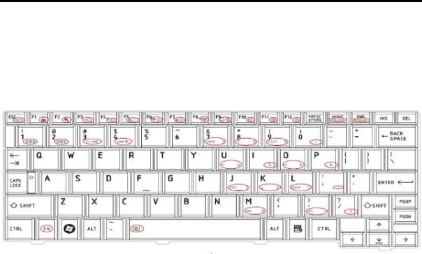
1.4 Keyboard
The Satellite T110, Satellite Pro T110, and PORTEGE T110 keyboard is for US style Figure 1-4-1 is a view of the keyboard for US style
Figure 1-4-1 Keyboard for US style
See Appendix E for details of the keyboard layout
Satellite T110 / Satellite Pro T110 /PROTEGE110 Maintenance Manual (960-Q08) |
11 |
Chapter 1 Hardware Overview
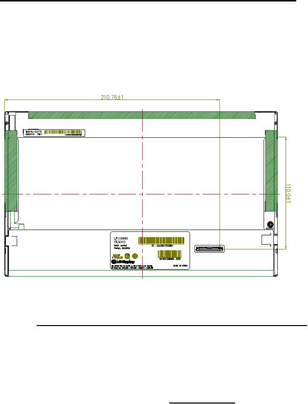
1.5 TFT Color Display
The Satellite T110 use LED to control backlight.
LCD Module
Figure 1-5-1 shows a view of the LCD module and Table 1-5-2 lists the specifications.
Figure 1-5-1 LCD Module
Item |
|
Specifications(WXGA+) |
|
||
SAMSUNGA |
CHI MEI |
|
LG |
AUO |
|
|
LTN116AT01-T01 |
N116B6-L02 |
|
LP116WH1-TLA1 |
B116XW02 V0 |
Number of |
1,366 x 3(R,G,B) x |
1,366 x 3(R,G,B) x |
|
1,366 x 3(R,G,B) x |
1,366 x 3(R,G,B) x |
Dots |
768 |
768 |
768 |
768 |
|
Dot spacing |
0.2265(H)× |
0.1875(H)× |
|
0.1875(H)× |
0.1875(H)× |
(mm) |
0.2265(V) |
0.1875(V) |
|
0.1875(V) |
0.1875(V) |
Display |
262,144 colors |
262,144 colors |
|
262,144 colors |
262,144 colors |
Colors |
|
||||
|
|
|
|
|
|
Table 1-5-2 LCD module specifications
Satellite T110 / Satellite Pro T110 /PROTEGE110 Maintenance Manual (960-Q08) |
12 |

Chapter 1 Hardware Overview
1.6 Power Rails
Table 1-6-1 lists the power rail output specifications of CULV platform.
Name |
|
Power supply Yes/No |
|
||
|
|
|
|
||
Voltage [V] |
Power OFF |
Power OFF |
No Battery |
||
|
|||||
|
Suspend mode |
Boot mode |
|||
|
|
|
|||
|
|
|
|
|
|
+5VPCU |
5 |
Yes |
Yes |
No |
|
|
|
|
|
|
|
+5V |
5 |
No |
No |
No |
|
|
|
|
|
|
|
+3VPCU |
3.3 |
Yes |
Yes |
No |
|
|
|
|
|
|
|
+3V_S5 |
3.3 |
Yes |
No |
No |
|
|
|
|
|
|
|
+3VSUS |
3.3 |
Yes |
No |
No |
|
|
|
|
|
|
|
+3V |
3.3 |
No |
No |
No |
|
|
|
|
|
|
|
+1.8VSUS |
1.8 |
Yes |
No |
No |
|
|
|
|
|
|
|
+SMDDR_VTERM |
1.8 |
Yes |
No |
No |
|
|
|
|
|
|
|
+SMDDR_VREF |
1.8 |
Yes |
No |
No |
|
|
|
|
|
|
|
+1.8V |
1.8 |
No |
No |
No |
|
|
|
|
|
|
|
+1.5V |
1.5 |
No |
No |
No |
|
|
|
|
|
|
|
+1.2V |
1.25 |
No |
No |
No |
|
|
|
|
|
|
|
+1.05v |
1.05 |
No |
No |
No |
|
|
|
|
|
|
|
+NB_CORE |
1.0~1.2 |
No |
No |
No |
|
|
|
|
|
|
|
VCC_CORE |
0.7~1.2 |
No |
No |
No |
|
Table 1-6-1 CULV Power supply output rating
Satellite T110 / Satellite Pro T110 /PROTEGE110 Maintenance Manual (960-Q08) |
13 |

Chapter 1 Hardware Overview
1.7 Batteries
The PC has the following two batteries.
Main battery
Real time clock (RTC) battery
Table 1-7-1 lists the specifications for these two batteries.
Battery Name |
Battery Element Output Voltage |
Main battery |
6 Cells |
Lithium ion |
10.8 V |
|
|
|
|
Real time clock |
COIN Type |
Lithium ion |
3V |
(RTC) battery |
Table 1-7-1 Battery specifications
1.7.1 Main Battery
The main battery is the primary power supply for the computer when the AC adapter is not connected. In Standby, the main battery maintains the current status of the computer.
Satellite T110 / Satellite Pro T110 /PROTEGE110 Maintenance Manual (960-Q08) |
14 |
Chapter 1 Hardware Overview
1.7.2 Battery Charging Control
Battery charging is controlled by a power supply microprocessor. The power supply microprocessor controls power supply and detects a full charge when the AC adaptor and battery are connected to the computer.
Battery Charge
When the AC adapter is connected, normal charging is used while the system is turned on and quick charge is used while the system is turned off. Refer to the following Table 1-7-2.
|
|
Power ON |
Power OFF |
|
|
|
|
|
6 cell |
5 ~ 10 hours |
about 5 hours |
|
|
|
|
|
Table 1-7 |
-2 Time required for charges of main battery |
|
Charge is stopped in the following cases. |
|
||
1.The main battery is fully charged
2.The main battery is removed
3.Main battery or AC adapter voltage is abnormal
4.Charging current is abnormal
Data preservation time
When turning off the power in being charged fully, the preservation time is as following Table 1-7-3.
|
Sleep |
|
Shut down |
6 cell |
About 3 days |
About 30 days |
|
|
Table |
1-7-3 Data preservation time |
|
Satellite T110 / Satellite Pro T110 /PROTEGE110 Maintenance Manual (960-Q08) |
15 |
Loading...