

Page 1

TX Platform
For TX Compact Utility Loaders
Model No. 22475 —Serial No. 270000001 and Up
Model No. 22476 —Serial No. 270000001 and Up
Form No. 3356-522 Rev A
Installation Instructions
Safety
General Operation
• Do not modify the platfor m or use it on
non–appro v ed mac hines .
• Ensure that the platfor m is properly attac hed
to the mac hine and is in g ood w orking order
prior to use .
• Allo w only the mac hine operator on the
platfor m.
• Do not allo w use of the platfor m b y untrained
operators .
• Use appropriate personal protecti v e apparatus
for eyes , feet, hands , and head.
• Look behind and do wn before bac king up to
be sure of a clear path. Use extra care when
operating in rev erse .
• Dismount and latc h the platfor m in the
transpor t position when loading and unloading
the mac hine .
• Do not place y our feet under the platfor m.
• Slo w do wn before tur ning . Shar p tur ns on any
ter rain ma y cause loss of control.
• Do not ste p off of the platfor m with the load
raised.
the unit in areas where there is sufficient
clearance for the operator to safely maneuv er
the platfor m.
• Ensure that the area is clear of other people
before operating the traction unit with the
platfor m. Stop the traction unit if any one
enters the area.
• Do not ex ceed the rated operating capacity , as
the traction unit with the platfor m ma y become
unstable whic h ma y result in loss of control.
Service
• Stop the engine before perfor ming any ser vice ,
re pairs , maintenance , or adjustments .
• K ee p n uts and bolts tight. K ee p equipment
clean and in g ood condition.
• Nev er tamper with safety devices . Chec k safety
systems for proper operation before eac h use .
• Stop and inspect the equipment if y ou strik e
an object. Mak e any necessar y re pairs before
restar ting .
• Use only g en uine re placement par ts to ensure
that original standards are maintained.
• K ee p y our hands , feet, hair , and loose clothing
a w a y from any mo ving par ts .
• Do not tr y to stabilize the traction unit b y
putting y our foot on the g round.
• Do not operate platfor m on rough and unev en
ter rain.
• Ensure that y ou operate the platfor m in areas
where there are no obstacles in close pro ximity
to the operator . F ailure to maintain adequate
distance from trees , w alls , and other bar riers
ma y result in injur y as the platfor m bac ks up
or tur ns during operation if the operator is not
attenti v e to the sur roundings . Only operate
© 2006—The Toro® Company
8111 Lyndale Avenue South
Bloomington, MN 55420
Register at www.Toro.com. Original Instructions (EN)
Printed in the USA.
All Rights Reserved
Page 2
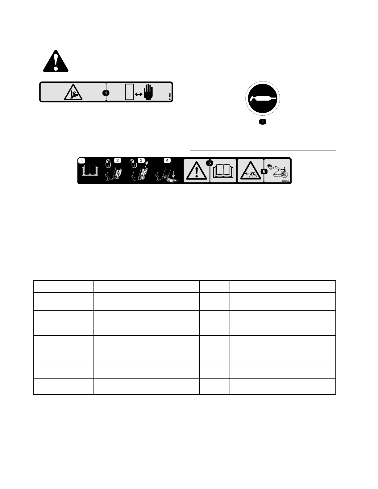
Safety and Instructional Decals
Safety decals and instr uctions are easily visible to the operator and are located near any
area of potential dang er . R e place any decal that is damag ed or lost.
94-3353
1. Crushing hazard of hand—keep your hands a safe distance
away.
112-2744
1. Read the Operator’s Manual.
2. Platform locked in storage position. 4. Lower the platform from the unlocked
3. Lift the platform up to unlock.
position to use.
58-6520
1. Grease
5. Warning—read the Operator’s Manual.
6. Tipping hazard—do not step off the
platform with a raised load.
Installation
Loose Parts
Use the chart below to verify that all parts have been shipped.
Step
1
2
3
4
5
No parts required
Platform assembly
Bolt (1/2 x 1-1/2 inches)
Flange-head nut (1/2 inch)
Counterweight
Bolt (1/2 x 1-1/4 inches)
Washer
Decal 112-2744
Handle
Flange-head bolts (5/16 x 3/4 inch)
Description
Qty.
–
1
4
4
1
4
4
1
1
2
Prepare the traction unit.
Install the platform.
Install the counter weight (TX 500
series traction units only).
Install the decal.
Install the handle.
Use
2
Page 3
Step
Step
1
Preparing the Traction Unit
No Parts Required
Procedure
1. Stop the engine , lo w er the loader ar ms , set the
parking brak e , and remo v e the k ey .
2. W ash all dir t and debris from the traction unit.
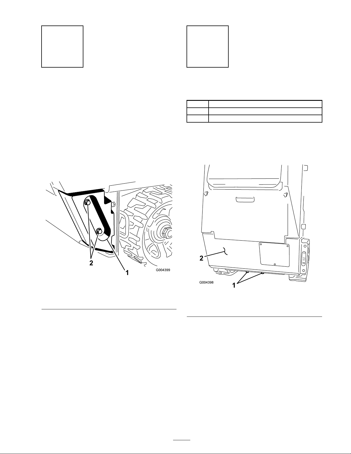
3. If y ou are installing this kit on a TX 400 series
traction unit, remo v e the counterw eights and
their fasteners from the rear of the traction
unit and store them in a safe location ( Figure 1 )
2
Installing the Platform
Parts needed for this step:
1
Platform assembly
4
Bolt (1/2 x 1-1/2 inches)
4
Flange-head nut (1/2 inch)
Procedure
1. Chec k and tighten the bottom 2 bolts securing
the lo w er rear panel to the frame ( Figure 2 ).
Figure 1
Left counterweight not shown
1. Counterweight
2. Fasteners
1. Bolts
2. Rear panel ( do not remove )
2. One at a time , remo v e and discard the 4 bolts
and n uts securing sides of the lo w er rear panel
to the frame , re placing eac h with a new bolt
(1/2 x 1-1/2 inc hes) installed from the front to
hold the space as pressure is released on the
rear panel ( Figure 3 ).
Important: Do not r emo v e the r ear
panel ( Figur e 2 ).
3
Figure 2
Page 4
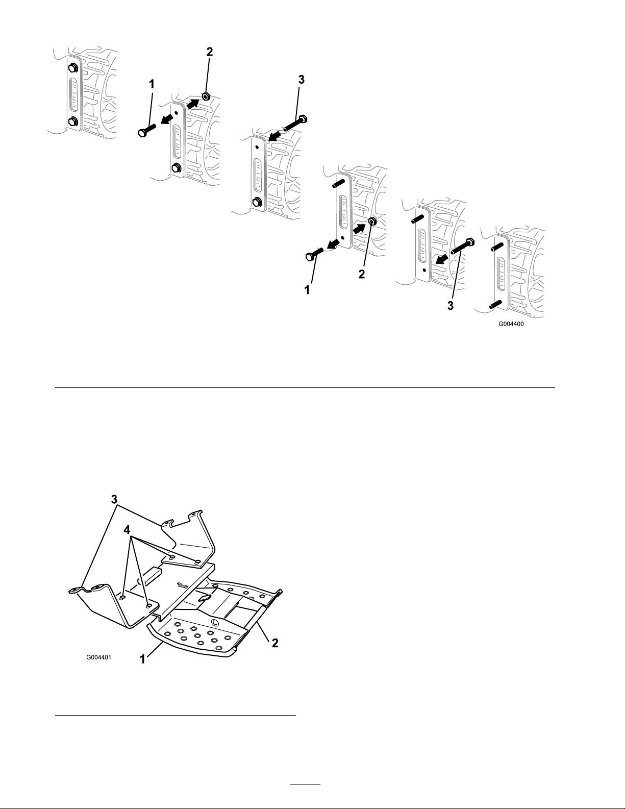
Figure 3
Left side not shown
1. Bolt (2 on each side) 2. Flange-head nut (2 on each side) 3. Bolt (1/2 x 1-1/2 inches)
Note: Figure 3 sho ws a TX 500 series
traction unit. If y ou ha v e a TX 400 series
traction unit it will look slightly different, but it
is configured similarly .
3. Grab the platfor m handle and pull up on it to
extend the platfor m ( Figure 4 ).
Figure 4
1. Platform assembly 3. Mounting bracket
2. Handle 4. Loosen these bolts
4. By hand, loosen, but do not remo v e , the 4
bolts and n uts securing the platfor m assembly
to the mounting brac k ets ( Figure 4 ).
5. Install the mounting brac k ets onto the 4 bolts
(1/2 x 1-1/2 inc hes) y ou inser ted earlier and
secure then with 4 flang e-head n uts (1/2 inc h)
( Figure 5 ).
4
Page 5

1. Flange-head nut (1/2 inch)
6. T or que the flang e-n uts to 67 to 83 ft-lb (91 to
113 N ⋅ m).
7. Align the platfor m so that it is centered on
the mac hine , then tor que the 4 bolts and
n uts securing the platfor m assembly to the
mounting brac k ets to 67 to 83 ft-lb (91 to 113
N ⋅ m) ( Figure 4 ).
Figure 5
2. Platform
5
Page 6

Step
Step
3
Installing the
Counterweight (TX 500
Series Traction Units Only)
Parts needed for this step:
1
Counterweight
4
Bolt (1/2 x 1-1/4 inches)
4
Washer
Procedure
If y ou are installing this kit on a TX 500 series
traction unit, install the counterw eight to the front
of the traction unit using 4 bolts (1/2 x 1-1/4
inc hes) and w ashers ( Figure 6 ). Apply a loc king
compound to the threads of the bolts before
installing them. T or que the bolts to 54 to 66 ft-lb
(73 to 89 N ⋅ m).
4
Installing the Decal
Parts needed for this step:
1
Decal 112-2744
Procedure
1. Clean the area behind the traction control
( Figure 7 ) so that there is not dir t or g rease
on it.
Figure 6
1. Bolt (1/2 x 1-1/4 inches)
2. Washer 4. Mounting holes
3. Counterweight
Figure 7
1. Decal position
2. R emo v e the bac king from the decal and secure
it in place ( Figure 7 ).
Note: T o k ee p from g etting bubbles under
the decal, press it do wn in the center first and
r ub it outw ard to w ard the edg es .
6
Page 7

Step
5
Installing the Handle
Parts needed for this step:
1
Handle
2
Flange-head bolts (5/16 x 3/4 inch)
Procedure
1. R emo v e the rear access co v er; refer to y ou
traction unit Operator’ s Manual for instr uctions .
2. Locate and drill 2 holes (3/8 inc h diameter) on
the control panel belo w the loader ar m lev er ,
as sho wn in Figure 8 .
Note: If the holes already exist, skip this ste p .
Figure 9
1. Handle
2. Control panel
3. Flange-head bolt (5/16 x
4. Install the rear access co v er .
3/4 inch)
Figure 8
1. 55/64 inch 3. 2 inches
2. 5-3/4 inches 4. Drill 3/8 inch diameter
holes
3. Secure the handle to the control panel using 2
flang e-head bolts (5/16 x 3/4 inc h) installed
from the inside ( Figure 9 ).
7
Page 8

Operation
If y ou step of f of the platf or m with a hea vy
load raised, the machine could tip f orw ard
quickl y , injuring y our and/or pinning
bystander s.
Do not step of f of the platf or m with the load
raised.
Unless y ou ar e car r ying hea vy loads or
attachments, the platf or m with an operator
will mak e the r ear of the machine the hea vy
end.
Al w ays k eep the hea vy end of the machine
uphill when operating on slopes.
Figure 10
T o unfold the platfor m, pull up on it until the latc h
releases and then swing it out and do wn ( Figure
11 ).
Y ou could f all of f of the platf or m and be
seriousl y injur ed during operation.
Do not mo v e the contr ols unless y ou ar e
standing with both feet on the platf or m and
y our hands ar e holding the handles.
Folding/Unfolding the
Platform
T o fold the platfor m, lift up on the bac k of it
and swing it to w ards the traction unit ( Figure 10 ).
W hen the latc h contacts the mounting plate , the
platfor m will slide do wn into the tube and will
loc k in place .
Figure 11
Using the Platform
T o use the platfor m, ste p onto it before star ting
the mac hine . Fully stop the mac hine and apply the
parking brak e before g etting off of the platfor m.
Use the reference bar and handle to stabilize
y ourself while riding on the platfor m.
8
Page 9

Maintenance
Greasing the Platform
Grease all pi v ot joints ev er y 8 operating hours and
immediately after ev er y w ashing .
Grease T ype: General-pur pose g rease .
1. Lo w er the loader ar ms and stop the engine .
R emo v e the k ey .
2. Clean the g rease fittings with a rag .
3. Connect a g rease gun to eac h fitting ( Figure
12 ).
Checking the Shear Bolt
Chec k the shear bolt ( Figure 13 ) for w ear , crac ks ,
or damag e ev er y 8 operating hours . R e place it if
it is damag ed.
Important: Use onl y a gen uine T or o
r eplacement shear bolt and n ut. Other bolts
will not function cor r ectl y and may lead to an
unsafe condition.
Figure 13
1. Shear bolt
Figure 12
4. Pump g rease into the fittings until g rease
begins to ooze out (appro ximately 3 pumps).
5. Wipe up any ex cess g rease .
9
Page 10

Page 11

Page 12

The Toro Compact Utility Loader Product
Line Warranty
A One-Year Limited Warranty
Conditions and Products Covered
The Toro® Company and its afliate, Toro Warranty Company, pursuant
to an agreement between them, jointly warrant your Toro Dingo Product
(“Product”) to be free from defects in materials or workmanship. The
following time periods apply from the date the Product is delivered to
the original retail purchaser:
Products Warranty Period
All traction units and
attachments
All engines
Where a warrantable condition exists, we will repair the Product at no
cost to you including diagnosis, labor, and parts.
1 year or 1000 operational hours,
whichever occurs rst
2 years
Instructions for Obtaining Warranty Service
If you think that your Toro Product contains a defect in materials or
workmanship, follow this procedure:
1. Contact any Authorized Dingo Service Dealer to arrange service
at their dealership. To locate a dealer convenient to you, access
our website at www.Toro.com. U.S. Customers may also call
800-348-2424.
2. Bring the product and your proof of purchase (sales receipt) to the
Service Dealer.
If for any reason you are dissatised with the Service Dealer’s analysis or
with the assistance provided, contact us at:
LCB Customer Service Department
Toro Warranty Company
8111 Lyndale Avenue South
Bloomington, MN 55420-1196
Toll Free: 888-577-7466 (U.S. customers)
Toll Free: 877-484-9255 (Canada customers)
Owner Responsibilities
You must maintain your Toro Product by following the maintenance
procedures described in the Operator’s Manual . Such routine
maintenance, whether performed by a dealer or by you, is at your
expense. Parts scheduled for replacement as required maintenance
(“Maintenance Parts”), are warranted for the period of time up to the
scheduled replacement time for that part. Failure to perform required
maintenance and adjustments can be grounds for disallowing a warranty
claim.
Items and Conditions Not Covered
Not all product failures or malfunctions that occur during the warranty
period are defects in materials or workmanship. This express warranty
does not cover the following:
• Product failures which result from the use of non-Toro replacement
parts, or from installation and use of add-on, modied, or
unapproved accessories
• Product failures which result from failure to perform required
maintenance and/or adjustments
• Product failures which result from operating the Product in an
abusive, negligent or reckless manner
• Parts subject to consumption through use unless found to be
defective. Examples of parts which are consumed, or used up, during
normal Product operation include, but are not limited to, digging
teeth, tines, spark plugs, tires, tracks, lters, chains, etc.
• Failures caused by outside inuence. Items considered to be outside
inuence include, but are not limited to, weather, storage practices,
contamination, use of unapproved coolants, lubricants, additives, or
chemicals, etc.
• Normal “wear and tear” items. Normal “wear and tear” includes,
but is not limited to, worn painted surfaces, scratched decals or
windows, etc.
• Any component covered by a separate manufacturer’s warranty
• Pickup and delivery charges
General Conditions
Repair by an Authorized Toro Service Dealer is your sole remedy under
this warranty.
Neither The Toro® Company nor Toro Warranty Company is liable for
indirect, incidental or consequential damages in connection with the
use of the Toro Products covered by this warranty, including any cost or
expense of providing substitute equipment or service during reasonable
periods of malfunction or non-use pending completion of repairs under
this warranty.
Some states do not allow exclusions of incidental or consequential
damages, or limitations on how long an implied warranty lasts, so the
above exclusions and limitations may not apply to you.
This warranty gives you specic legal rights, and you may also have other
rights which vary from state to state.
Except for the Emissions warranty referenced below, if applicable, there is
no other express warranty. All implied warranties of merchantability and
tness for use are limited to the duration of this express warranty.
Note to California residents: The Emissions Control System on your
Product may be covered by a separate warranty meeting requirements
established by the U.S. Environmental Protection Agency (EPA) or the
California Air Resources Board (CARB). The hour limitations set forth above
do not apply to the Emissions Control System Warranty. Refer to the
California Emission Control Warranty Statement printed in you operator’s
manual or contained in the engine manufacturer’s documentation for
details.
Countries Other than the United States or Canada
Customers who have purchased Toro products exported from the United States or Canada should contact their Toro Distributor (Dealer) to obtain
guarantee policies for your country, province, or state. If for any reason you are dissatised with your Distributor’s service or have difculty obtaining
guarantee information, contact the Toro importer. If all other remedies fail, you may contact us at Toro Warranty Company.
Rev
 Loading...