

Page 1

Pick-UpBroomGutterBrush
TXL2000ToolCarrier
ModelNo.22544
Installation
LooseParts
Usethechartbelowtoverifythatallpartshavebeenshipped.
FormNo.3426-135RevC
InstallationInstructions
Description
Nopartsrequired
Gutterbrushmanifold
Gutterbrusharm
Brushhead1
Bolt(7/16x1inch)
Lockwasher1
Flatwasher1
Hitchpin1
Hitchclip1
Shorthoses
Elbowtting
Narrowhoses2
Nopartsrequired
PreparingtheMachine
Important:Thiskitinstallstothepick-upbroom;
acquirethepick-upbroombeforeinstallation.
Note:Thegutterbrushcanbeinstalledontheright
orleftsideofthepickupbroom;thismanualshows
theinstallationtotherightside.
Qty.
Use
–
1
1
3
2
1
–
Preparethemachine.
Installthegutterbrush.
Installthehoses.
Completetheinstallation.
Note:Determinetheleftandrightsidesofthe
machinefromthenormaloperatingposition.
1.Parkthetractionunitonalevelsurface.
2.Disengagetheauxiliaryhydraulics.
3.Loweranyequippedattachments;refertoyour
Operator’sManual.
4.Engagethetractionunitparkingbrake.
5.Shutoffthetractionunitengineandremovethe
key.
6.Disconnectthetractionunitbattery;refertoyour
Operator’sManual.
©2019—TheToro®Company
8111LyndaleAvenueSouth
Bloomington,MN55420
Registeratwww.T oro.com.
OriginalInstructions(EN)
PrintedintheUSA
AllRightsReserved
*3426-135*C
Page 2

InstallingtheGutterBrush
Important:Youmaydiscardallremovedparts
unlessotherwisenoted.
WARNING
Seekimmediatemedicalattentionifuidis
injectedintoskin.Injecteduidmustbe
surgicallyremovedwithinafewhoursbya
doctor.
•Ensurethatallhydraulic-uidhoses
andlinesareingoodconditionandall
hydraulicconnectionsandttingsaretight
beforeapplyingpressuretothehydraulic
system.
•Keepyourbodyandhandsawayfrom
pinholeleaksornozzlesthateject
high-pressurehydraulicuid.
•Usecardboardorpapertondhydraulic
leaks.
•Safelyrelieveallpressureinthehydraulic
systembeforeperforminganyworkonthe
hydraulicsystem.
4.Installthebrushheadtothegutterbrushusing
thebolt,lockwasherandretainingwasher
(Figure2).
g284029
Figure2
1.Removethenutandboltsecuringthehose
clamptothemanifoldmountingbracketonthe
leftsideofthemachineandremovetheclamp.
2.Installthegutterbrushmanifoldtothemanifold
mountingbracketwiththe3bolts(7/16x1inch),
lockwashers,andatwashers(Figure1).
Figure1
1.Bolt(7/16x1inch)
2.Lockwasher
3.Flatwasher
4.Gutterbrushmanifold
3.Removethebolt,lockwasher,andretaining
washerfromthebottomofthegutter-brush
broommotor.
1.Gutterbrushmotorshaft
2.Retainingwasher4.Bolt
3.Lockwasher
5.Positionthegutterbrushonthedesiredside
ofthepick-upbroomandinstallthehitchpin
throughthemountholes(Figure3).
g269186
g269239
Figure3
1.Hitchpin3.Hitchclip
2.Gutterbrushmount(left
side)
4.Gutterbrushmount(right
side)
2
Page 3

6.Securethegutterbrushtothecornerofthe
pick-upbroomwiththeadjustmentchain;refer
toAdjustingtheGutterBrushHeight(page5).
7.Markwhichhoseisinwhichportonthepick-up
broommotoranddisconnectthehoses;plug
thehoseendsandsetthemasideforlater
installation.
8.Supportthepick-upbroombrushandbroom
shaftsothatthebroomwillnotfallwhen
removingthepick-upbroomhydraulicmotor.
9.Removethenuts(1/2inch)andboltssecuring
thepick-upbroomhydraulicmotorandmount
bracket,rotatetheassemblyclockwise90°,and
installtherotatedassemblywiththeremoved
hardware(Figure4).
10.RemovethestraightttingsinstalledintheA
andBportsofthemotormanifold.
Note:Youmayneedtoremove1ofthe
socket-headcapscrewstoaccomplishthis.
InstallingtheHoses
1.Installtheshorthosestothemotormanifold
ports;connectthehoseinpick-upbroommotor
port“B”tothegutterbrushmanifoldport“M1”
andthehoseinpick-upbroommotorport“A”to
gutterbrushmanifoldport“M2”.
2.Connectthehosethatwasconnectedtopick-up
broommotorport“A”toport“P2”onthegutter
brushmanifold.
3.Connectthehosethatwasconnectedtopick-up
broommotorport“B”toport“P1”onthegutter
brushmanifold.
Figure4
1.Routethecasedrainhose
throughhere.
2.Elbowtting
3.Casedrainplughole
6.Installthenarrowhosesfromthegutterbrush
manifoldtothegutterbrushmotoraccordingto
theinstructionsbelow:
•Ifthegutterbrushismountedontheright
sideofthepick-upbroom,routethehoses
throughbothhoseguides,connectthehose
fromport“A”onthegutterbrushmotorto
port“M3”onthegutterbrushmanifold,and
connectthehosefromport“B”toport“M4”
(Figure5).
•Ifthegutterbrushismountedontheleft
sideofthepick-upbroom,routethehoses
throughthecenterhoseguide,connectthe
gutterbrushhosefromport“A”onthegutter
brushmotortoport“M4”onthegutterbrush
manifold,andconnectthehosefromport“B”
toport“M3”.
g269295
4.Removethecasedrainplugonthepick-up
broomhydraulicmotor(locatedontheopposite
sideofthemotorfromthehoseports).
5.Installtheelbowttingorientedsothatthetting
pointstowardtheholeinthemotorguard.
3
Page 4
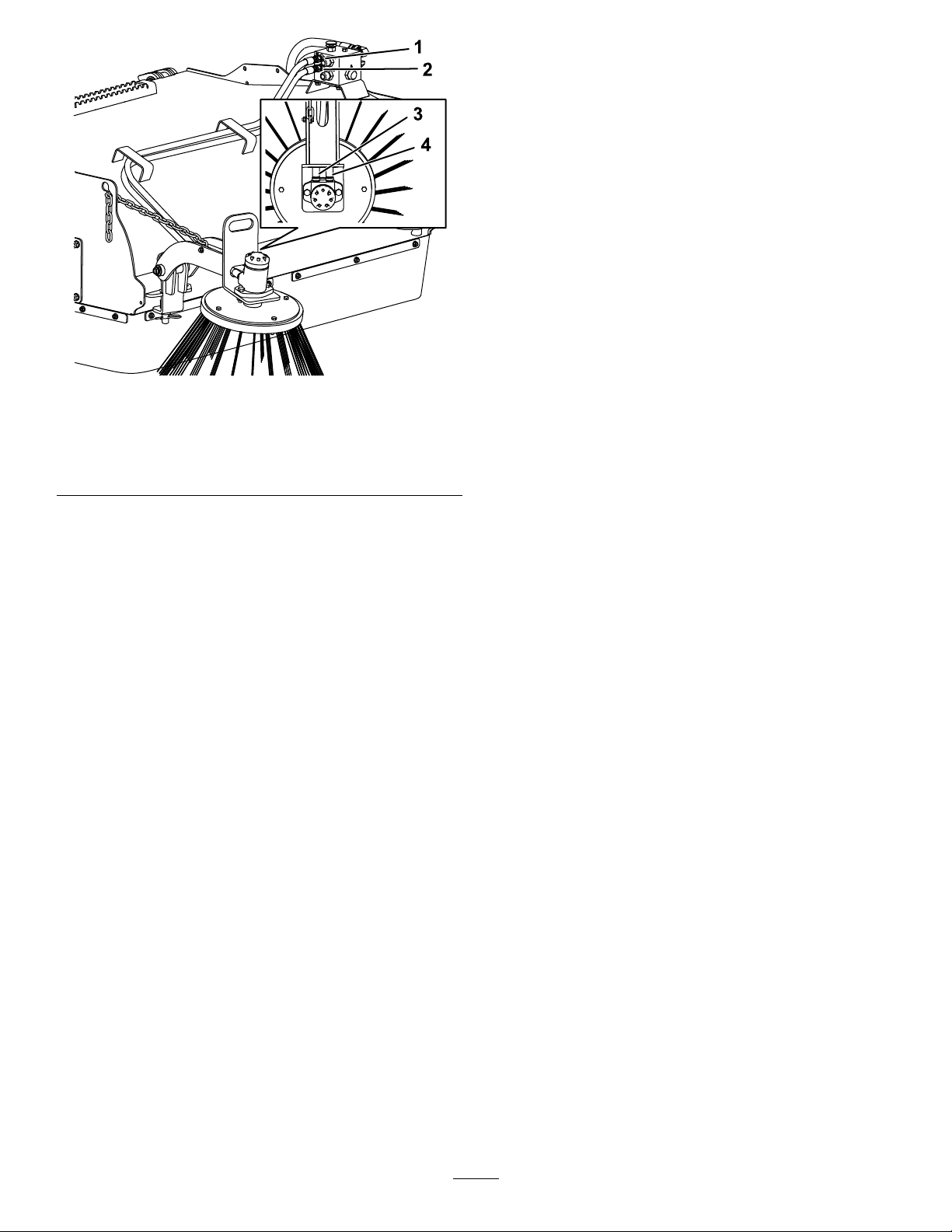
Figure5
Rightsidemountshown
1.Port“M3”3.Port“A”
2.Port“M4”
4.Port”B”
CompletingtheInstallation
1.Tightenallthehoseconnections.
2.Connectthetractionunitbattery;refertoyour
Operator’sManual.
3.Turnonthetractionunitandtestthegutterbrush
operation;withthepick-upbroomspinning
forward(clockwisewhenlookingfromthemotor
end),thegutterbrushshouldthrowmaterialin
frontofthepick-upbroom.
4.Ifthegutterbrushdoesnotspinwiththepick-up
broomspinningforward,runthebroominthe
reversedirection;ifthegutterbrushspins,the
narrowhosesareinstalledincorrectly.
Note:Wheninstalledcorrectly,thegutterbrush
g269332
doesnotoperatewhenthepick-upbroomis
spinningbackward.
5.Ifanyhydraulicuidwasspilled,ensurethatthe
tractionunithydraulicuidisatthecorrectlevel;
refertoyourtractionunitOperator’sManual.
7.Connectthecasedrainhosetothegutterbrush
manifoldandtotheelbowttingofthepick-up
broomandsecurethecasedrainhosetothe
motorhoseswithzipties.
4
Page 5
Operation
AdjustingtheGutterBrush
Speed
Thegutterbrushisequippedwithavariable-speed
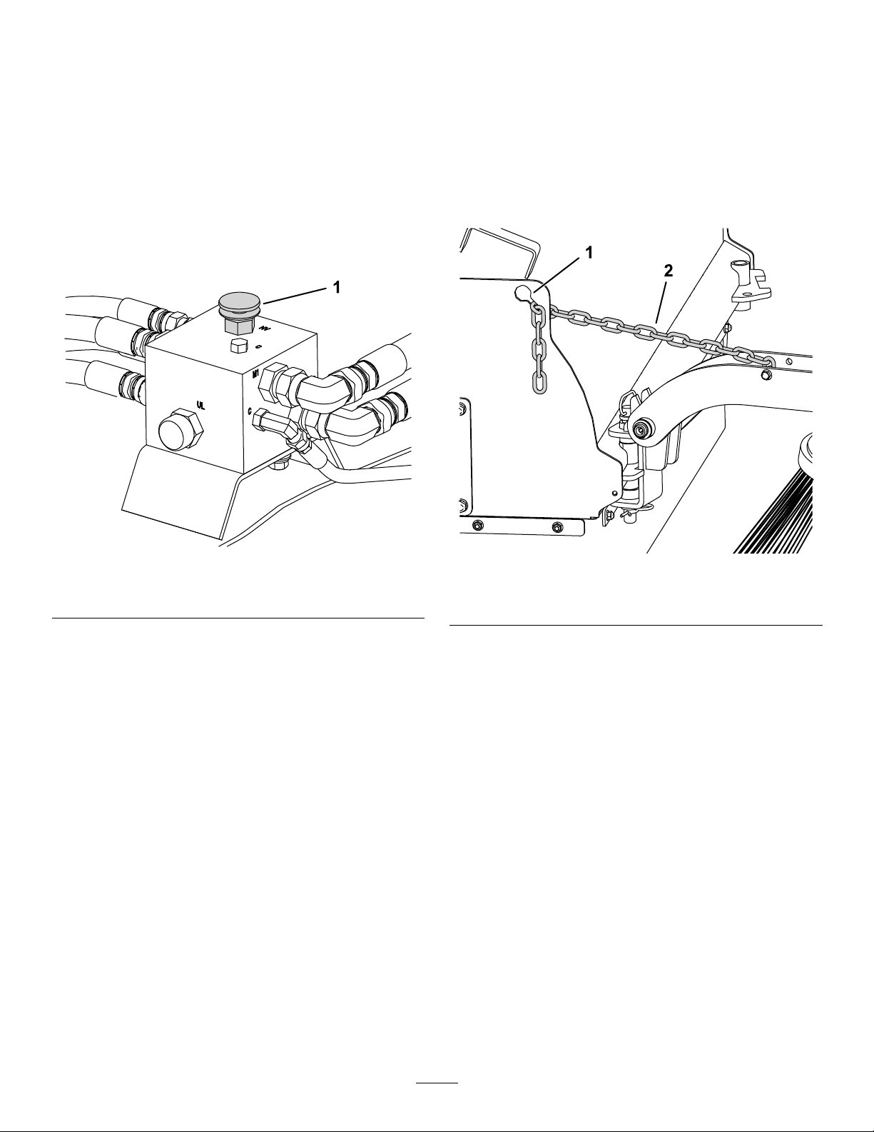
knobontopofthegutterbrushmanifold(Figure6).
Turnthisknobcounterclockwisetolowerthespeed,
andturnitclockwisetoincreasethespeedof
thegutterbrush.Turningtheknoballtheway
counterclockwiseturnsoffthegutterbrush.
AdjustingtheGutterBrush
Height
Adjustthepositionoftheadjustmentchaintoraise
orlowerthegutterbrush.Liftuponthebrushand
placetheadjustmentchainintheslotforthedesired
brushheight(Figure7).
Whenthegutterbrushisnotinuse,pullthechainback
asfaraspossibletoraiseitintothestorageposition.
1.Variable-speedknob
Figure6
g269343
Figure7
1.Chainslot
2.Adjustmentchain
g269252
5
Page 6
Maintenance
LubricatingtheBrush
Cutter
1.Parkthetractionunitonalevelsurface,engage
theparkingbrake,andlowertheloaderarms.
2.Shutoffthetractionunitengineandremovethe
key.
3.Cleanthegreasettingswitharag.
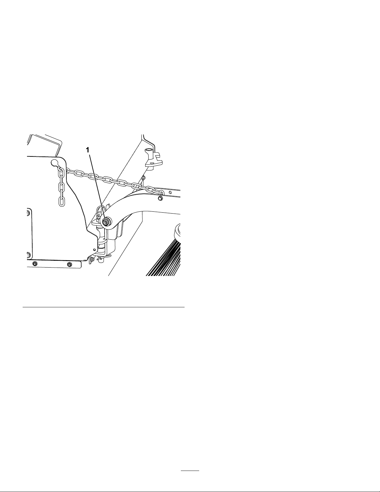
4.Connectagreaseguntothebrushcutterhinge
pingreasetting(Figure8).
MiscellaneousMaintenance
•Checkforwearonbrushhead;ifthewirelengthof
thegutterbrushislessthan15.25cmor6inches
(abouthalftheoriginallength),thebrushhead
needstobereplaced.
•Checkforloose,worn,ormissingparts,repairor
replaceasneeded.
•Removeanyforeigndebrissuchasstring,wire,
etc.thatmayhavewrappedaroundthebrush
head.
•Inspectthegutterbrushmotor,manifold,hydraulic
ttingsandhosesforleaksanddamage.Replace
asneeded.Ensurethatthemachineisshutoff
andhydraulicpressureisrelievedbeforechecking
forleaks.Neveruseyourhandstocheckfor
high-pressurehydraulicleaks.
•ContactyourAuthorizedServiceDealerforany
requiredreplacementparts.
Figure8
1.Greasetting
5.Pumpgreaseintothettingsuntilgreasebegins
tooozeoutofthebearings.
6.Wipeupanyexcessgrease.
g269344
6
Page 7

Notes:
Page 8

 Loading...