

Page 1
]
2
]
2
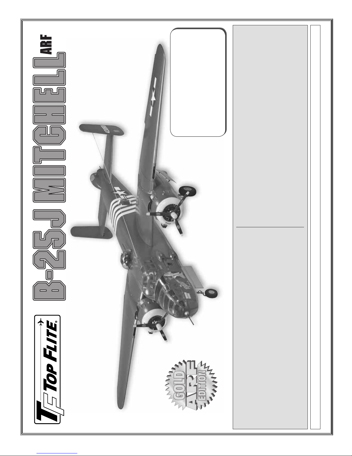
Wingspan: 88.5 in [2255mm]
Wing Area: 1036 sq in [66.8 dm
Weight: 17- 19 lbs [7710 – 8620g]
Wing Loading: 38 – 42 oz/sq ft [115 – 129g/dm
Length: 71 in [1795mm]
Scale: 1/9th (11%)
Radio: 8-channel, 13 servos
Hobby Services
3002 N. Apollo Dr. Suite 1
Champaign IL 61822 USA
.46 – .50 cu in [7.5 – 8.0cc] two-strokes
Engine: .70 cu in [11.5cc] four-strokes,
If the buyer is not prepared to accept the liability associated with the use of this
product, the buyer is advised to return this kit immediately in new and unused
condition to the place of purchase.
To make a warranty claim send the defective
part or item to Hobby Services at the address:
Include a letter stating your name, return shipping address, as much contact information
as possible (daytime telephone number, fax number, e-mail address), a detailed
description of the problem and a photocopy of the purchase receipt. Upon receipt of
the package the problem will be evaluated as quickly as possible.
WARRANTY.....Top Flite Models guarantees this kit to be free
from defects in both material and workmanship at the date of purchase. This warranty
does not cover any component parts damaged by use or modifi cation. In no case shall
Top Flite’s liability exceed the original cost of the purchased kit. Further, Top Flite
reserves the right to change or modify this warranty without notice.
In that Top Flite has no control over the fi nal assembly or material used for fi nal
assembly, no liability shall be assumed nor accepted for any damage resulting from
the use by the user of the fi nal user-assembled product. By the act of using the user-
assembled product, the user accepts all resulting liability.
READ THROUGH THIS MANUAL BEFORE STARTING CONSTRUCTION. IT CONTAINS IMPORTANT INSTRUCTIONS AND WARNINGS CONCERNING THE ASSEMBLY AND USE OF THIS MODEL.
Top Flite Models Champaign, IL Telephone (217) 398-8970, Ext. 5 airsupport@top-fl ite.com
Entire Contents © Copyright 2007 TOPZ0980 for TOPA0980 V1.0
Page 2

doors on the full-size B-25 close both after the gear
has retracted and after it has extended (look at photos
of a B-25 sitting on the tarmac—notice that the gear
doors are closed!). But rather than duplicating the
full-size confi guration (which would require a larger
radio with additional channels, air control valves on
every door, additional pushrods, linkages, air lines,
sequencers and considerable time, expense and
skill), and rather than abandoning functioning doors
altogether, we did it the “hard way” back in the shop by
taking time to fi gure out how to incorporate operating,
scale-appearing landing gear doors that the average
SCALE FEATURES .......................................... 3535
Mount the Nose-Gunner Canopy ........................ 37
Install the Nose-Gunner Cabin ........................... 38
Mount the Top Turret & Machine Guns................ 38
Finish the Tail-Gunner Cabin ..............................39
Mount Side Gun Packs & Waist Gun Windows ...40
Mount the ADF “Football” Antenna ..................... 41
Mount the Propeller Hubs ................................... 41
Apply the Decals ................................................. 41
GET THE MODEL READY TO FLY ....................... 41
Balance the Model (C.G.) ................................... 42
Balance the Model Laterally ............................... 42
ARF builder could both afford and assemble. The
Top Flite B-25 ARF features operating, spring-loaded
doors that use mechanical levers to open and close,
PREFLIGHT .......................................................... 42
Check the Control Directions .............................. 43
Set the Control Throws ....................................... 43
thus eliminating all the aforementioned paraphernalia
that would be required.
And while other scale details including the nose-
gunner interior, cockpit interior, tail-gunner canopy
Identify Your Model ............................................. 43
Charge the Batteries ........................................... 43
Balance Propellers ............................................. 43
Ground Check ..................................................... 43
Range Check ...................................................... 44
and machine guns are not exact replicas, these scale
features still “get the point across” with their presence
and stand-off accuracy. With all this detail also comes
the time commitment to put it all together, but in the
end we know it will all be worthwhile when you’re
executing slow fl y-bys straight down the runway with
the fl aps and gear extended and everybody else at
the fi eld standing by watching.
ENGINE SAFETY PRECAUTIONS .......................44
AMA SAFETY CODE (Excerpts) ......................... 44
CHECK LIST ......................................................... 45
FLYING .................................................................. 45
Mount the Wings ................................................. 45
Takeoff ................................................................ 46
Flight ................................................................... 46
B-25 Engine-Out Flying Procedures ................... 46
Single Engine-Out Procedures ........................... 46
The “Gold” B-25 is also a user-friendly model for breaking
Landing ............................................................... 47
down for transport and set up. Most modelers will simply
SERVO EXTENSION CHARTS .............................48
remove the outboard wing panels allowing the model to
ENGINE MOUNT TEMPLATES ............................ 51
fi t easily into a mini van. If it’s still too big, the inboard
wing panels and vertical and horizontal stabilizers can
also be easily removed with the sturdy building stand
supporting the model during the process.
INTRODUCTION
For the latest technical updates or manual corrections
to this model visit the Top Flite web site at www.top-
fl ite.com. Open the “GOLD EDITION ARFS” link on
the left side of the page and click on image of the B-25
that appears. If there is new technical information or
changes there will be an “Important! TECH NOTICE”
-scale B-25J Mitchell ARF. While no ARF model
th
Thank you for purchasing the Top Flite Gold Edition
1/9
will provide the level of detail necessary to take
“high-static” at premier scale competitions, you’ll still
be amazed at the level of detail and the number of
scale features included with this model! And we’ve
done our best to balance the level of authenticity and
box on the upper left corner of the page. Click on the
Tech Notice box to read the info.
2
detail with the requirements for simplicity that an ARF
modeler expects. For example, the main landing gear
TABLE OF CONTENTS
INTRODUCTION ..................................................... 2
Scale Competition ................................................3
Academy of Model Aeronautics ............................ 3
IMAA ..................................................................... 3
SAFETY PRECAUTIONS .......................................3
DECISIONS YOU MUST MAKE .............................. 4
Engine Recommendations ...................................4
Retractable Landing Gear .....................................4
Radio Equipment .................................................. 4
ADDITIONAL ITEMS REQUIRED ..........................5
Hardware and Accessories ................................... 5
Adhesives and Building Supplies ..........................5
Optional Supplies and Tools .................................5
Covering Tools ...................................................... 5
KIT INSPECTION .................................................... 6
ORDERING REPLACEMENT PARTS .................... 6
PREPARATION ....................................................... 9
ASSEMBLE THE WING PANELS ........................... 9
Hinge the Flaps and Ailerons ...............................9
Mount the Engines .............................................. 10
Hook Up the Throttle and Install the Fuel Tank ... 11
Mount the Main Landing Gear ............................ 12
Retract Installation ........................................... 12
Fixed Gear Installation .....................................13
Mount the Fiberglass Nacelle Covers ................. 13
Mount the Main Landing Gear Doors
(Retracts Only) ................................................14
Hook Up the Main Landing Gear Doors .............16
Mount the Cowl ................................................... 19
Mount the Replica Engines ................................. 22
Hook Up the Flaps and Ailerons ......................... 23
ASSEMBLE THE TAIL .......................................... 24
Hinge the Elevators and Rudders ....................... 24
Hook Up the Rudders and Elevators .................. 25
Mount the Nose Gear ......................................... 26
Hook Up the Nose Gear Door
(Retract Only) .................................................. 29
FINAL ASSEMBLY ............................................... 30
Assemble the Cockpit ......................................... 30
Hook Up the Air System ..................................... 31
Complete the Radio Installation .......................... 32
Mount the Inboard Wing Panels .......................... 33
Mount the Outboard Wing Panels .......................34
Page 3
PROTECT YOUR MODEL, YOURSELF AND
OTHERS. FOLLOW THESE IMPORTANT
SAFETY PRECAUTIONS
1. Your Top Flite B-25J Mitchell ARF should not be
considered a toy, but rather a sophisticated, working
model that functions very much like a full-size
airplane. Because of its performance capabilities, the
B-25 ARF, if not assembled and operated correctly,
could possibly cause injury to yourself or spectators
and damage to property.
2. You must assemble the model according to the
instructions. Do not alter or modify the model, as
doing so may result in an unsafe or unfl yable model.
In a few cases the instructions may differ slightly from
the photos. In those instances the written instructions
should be considered as correct.
3. You must take time to build straight, true
and strong.
4. You must use an R/C radio system that is in good
condition and correctly sized engine and components
as specifi ed in this instruction manual. All components
must be correctly installed so that the model operates
correctly on the ground and in the air. You must check
the operation of the model and all components before
every fl ight.
5. If you are not an experienced pilot or have not
fl own this type of model before, we recommend that
you get the assistance of an experienced pilot in your
R/C club for your fi rst fl ights. If you’re not a member
of a club, your local hobby shop has information
about clubs in your area whose membership includes
experienced pilots.
6. While this kit has been fl ight tested to exceed
normal use, if the plane will be used for extremely
high stress fl ying, or if engines larger than ones in
the recommended range are used, the modeler is
responsible for taking steps to reinforce the high
stress points and/or substituting hardware more
suitable for the increased stress.
Fax (765) 741-0057
Tele. (800) 435-9262
Muncie, IN 47302-9252
5151 East Memorial Drive
Academy of Model Aeronautics
ACADEMY OF MODEL AERONAUTICS
If you are not already a member of the AMA, please
join! The AMA is the governing body of model
aviation and membership provides liability insurance
coverage, protects modelers’ rights and interests and
is required to fl y at most R/C sites.
(or 11%). These
th
Or via the Internet at: http://www.modelaircraft.org
IMPORTANT!!! Two of the most important things you
3
IMAA
(913) 823-5569
Salina, KS 67401
205 S. Hilldale Road
can do to preserve the radio controlled aircraft hobby
are to avoid fl ying near full-scale aircraft and avoid
fl ying near or over groups of people.
IMAA
The Top Flite B-25 ARF qualifi es as a “giant-scale” model
and is therefore eligible to fl y in IMAA (International
Miniature Aircraft Association) events. The IMAA is an
organization that promotes non-competitive fl ying of
giant-scale model aircraft. If you plan on attending an
IMAA event refer to the IMAA Safety Code at www.
fl y-imaa.org under the “Sanctions” heading in their
site index. IMAA contact information is also available
in Model Aviation, the monthly newsletter magazine
from the AMA. The IMAA can also be contacted at the
address or telephone number below:
3114 Yukon Ave
Fax: (714) 979-7279
Costa Mesa, CA 92626
Bob’s Aircraft Documentation
Telephone: (714) 979-8058
e-mail: www.bobsairdoc.com
SCALE COMPETITION
The scale of this model is 1/9
fi gures were derived from comparing the wing span
and fuselage length of this model to the wingspan and
fuselage length of the full-size. Though the Top Flite
B-25J Mitchell is an ARF and may not have the same
level of detail as an “all-out” scratch-built competition
model, it is a scale model nonetheless and is therefore
eligible to compete in the Fun Scale class in AMA
competition (we receive many favorable reports of
our ARFs in scale competition!). In Fun Scale, the
“builder of the model” rule does not apply. To receive
the fi ve points for scale documentation, the only proof
required that a full size aircraft of this type in this paint/
markings scheme did exist is a single sheet such as a
kit box cover from a plastic model, a photo, or a profi le
painting, etc. If a black-and-white photo is used, other
written documentation of color must be provided.
Contact the AMA for a rule book with full details. See
below for the AMA contact information.
If you would like photos of the full-size B-25J for
scale documentation, or if you would like to study the
photos to add more scale details, photo packs are
available from:
Page 4
bicycle air compressor. The power cord may have to
be converted from a cigarette lighter connector to
alligator clips or something that can be connected
to your 12V battery. Connect Robart’s air fi ller to the
RETRACTABLE LANDING GEAR
compressor with a length of Robart air line.
Your B-25J Mitchell ARF may be assembled with the
included fi xed landing gear or retractable landing
gear. If fi xed landing gear is used, no additional items
will be needed to install the gear. If installing retracts,
RADIO EQUIPMENT
If fl ying the B-25 with fi xed landing gear seven
channels will be required; one channel for the
ailerons, one for elevator, one for each engine, one
for the rudder, one for the fl aps and one channel for
the nose steering servo. The engines could be linked
with a Y-harness, but it is recommended to link the
throttles electronically via mixing in the transmitter.
retractable main landing gear (ROBQ1624)
Kit—includes pressure vessel, air line tubing,
variable-rate air valve, T-fi ttings (ROBQ2305)
this model is designed for Robart pneumatic retracts.
Following is the complete list of items required to
install the Robart retracts:
❏ Robart #TFB25 Top Flite B-25J ARF pneumatic
❏ Robart #157VRX Large-Scale Deluxe Air Control
❏ #190 Air Line Quick Disconnects (ROBQ2395)
❏ Standard size servo to operate air control valve
Then, the throttles can be “decoupled” using a switch
on the transmitter for starting and tuning the engines
individually. It is also recommended to link the rudder
servos and nose steering servo electronically through
mixing in your transmitter so the nose steering servo
can be trimmed separately from the rudders.
If installing retractable landing gear eight channels
will be required, with an additional standard servo to
operate the air control valve.
(HCAR5500) will be helpful
™
Additionally, a hobby can of compressed air such
as Hobbico Duster
for cycling the retracts during assembly and setup
without having to connect the gear to the air control
valve, fi ller and air tank before it is ready.
Regarding servos, the ailerons, fl aps, nose steering
and air control valve may all be operated with standard
servos (such as Futaba S3003—FUTM0031). A
stronger ball bearing servo with no less than 50 oz.
in. of torque (such as the Futaba 9001—FUTM0075)
should be used on the elevator. Two mini servos with
a torque rating of at least 35 oz.-in. (such as Futaba
S3115—FUTM0415) are required on the rudders.
Note: Keep in mind that the standard servo
recommendations for the fl aps and ailerons are the
minimums. Higher-torque, ball bearing servos could
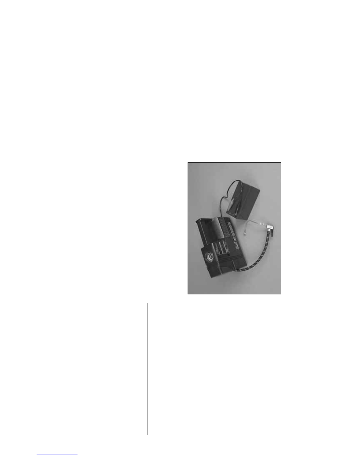
An air pump will also be required for fi lling the on-
board air tank when you get to the fi eld and it’s time
be used for more fl ight precision.
The following servo extensions and Y-harnesses were
also used in this model. See the diagrams on pages
to fl y. The Robart Hand Pump & Gauge (ROBQ2363)
could be used, but will require considerable time (and
effort!) to fi ll the tank. Instead, we recommend an
electric hobby air compressor (with a pressure gauge).
48-49 that shows where all the extensions are used.
4
What we use in our R&D shop is simply a small 12V
We, as the kit manufacturer, provide you with a top
quality, thoroughly tested kit and instructions, but
ultimately the quality and fl yability of your fi nished
9. WARNING: Some of the parts in this kit are made
of fi berglass, the fi bers of which may cause eye,
skin and respiratory tract irritation. Never blow into
one of these parts to remove fi berglass dust, as
the dust will blow back into your eyes. Always wear
safety goggles, a particle mask and rubber gloves
when grinding, drilling and sanding fi berglass parts.
Vacuum the parts and the work area thoroughly after
working with fi berglass parts.
model depends on how you build it; therefore, we
DECISIONS YOU MUST MAKE
cannot in any way guarantee the performance of
your completed model, and no representations
are expressed or implied as to the performance or
safety of your completed model.
Remember: Take your time and follow the
instructions to end up with a well-built model that
is straight and true.
This is a partial list of items required to fi nish this
model that may require planning or decision making
before starting assembly. Order numbers are provided
in parentheses.
ENGINE RECOMMENDATIONS
As specifi ed on the front cover of this instruction manual,
the Top Flite B-25J ARF is intended for twin .70 four-
strokes or .46-.50 two-strokes. There isn’t much more
that can be said other than it is unnecessary (as well
as inadvisable) to overpower this model with larger
engines. Engines in the specifi ed range will provide
more than enough thrust to fl y this model in a scale-like
manner with plenty of extra power to perform evasive
maneuvers if the situation arises. Bottom line is with
two-stroke .46’s or four-stroke .70’s you’ll fi nd yourself
cruising around at half-throttle most of the time.
Page 5

parts (HCAR0667)
K&S #801 Kevlar thread or fi shing Kevlar thread)
(See page 22)
❏ Curved-Tip Canopy Scissors for trimming plastic
❏ Non-Elastic String for stab alignment (such as
❏ 9/32" [7mm] O.D. K+S brass tube for fueling line
❏ Masking tape (TOPR8018)
❏ 3M 77 Spray Adhesive (MMMR1990)
❏ AccuThrow Defl ection Gauge (GPMR2405)
(GPMR2400)
™
❏ CG Machine
❏ Laser Incidence Meter (GPMR4020)
❏ Precision Magnetic Prop Balancer (TOPQ5700)
COVERING TOOLS
A covering iron will be required for tightening the
covering on the model after it is removed from the
Sealing Iron (COVR2700)
®
Century
ST
box. Following are the covering tools recommended:
❏ 21
Century Iron Cover (COVR2702)
Century Trim Seal Iron (COVR2750)
ST
ST
❏ 21
❏ 21
Micro Torch II
™
The Top Flite B-25 ARF is factory covered with
Top Flite MonoKote fi lm. Should repairs ever
be required, following is a list of colors used on
this model and order numbers for 6' [1.8m] rolls.
(At some hobby shops MonoKote can also be
purchased by the foot.)
Flat Olive Drab (TOPQ0510)
Flat Dove Gray (TOPQ0511)
Flat Black (TOPQ0508)
Panel Line Pen—
®
White (TOPQ0204)
Note: The stabilizer and wing incidences and engine
thrust angles have been factory-built into the B-25.
However, some technically-minded modelers may
wish to check these measurements anyway. To view
this information, visit the web site at www.top-fl ite.com
and click on “Technical Data.” Due to manufacturing
tolerances which will have little or no effect on the
way the model will fl y, there may be slight deviations
between your model and the published values.
Engine Mount Hole Locator
™
5
or 4 oz. [113g] Aerosol (GPMR634)
❏ 1 oz. [30g] Thin Pro CA (GPMR6002)
❏ 1 oz. [30g] Medium Pro CA+ (GPMR6008)
❏ CA Applicator Tips (HCAR3780)
assembling this model. These are long-handle Allen
wrenches that will be invaluable for mounting the
cowls and other the scale details.
❏ (4) 6" [150mm] extensions (HCAM2701 for Futaba)
❏ (2) 12" [300mm] extensions (HCAM2711 for Futaba)
❏ (5) 24" [600mm] extensions (HCAM2721 for Futaba)
❏ (1) 36" [910mm] extension (HCAM2726 for Futaba)
❏ (5) Y-harnesses (HCAM2751 for Futaba)
❏ CA Activator 2 oz. [57g] Spray Bottle (GPMR6035),
A minimum 2,000mAh receiver battery could be
used, but you will have to closely monitor the battery’s
capacity and voltage to avoid draining the battery
(TOPR1090)
❏ Pro 30-Minute Epoxy (GPMR6047)
❏ Milled Fiberglass (GPMR6165) -OR- Microballoons
❏ Threadlocker Thread Locking Cement (GPMR6060)
❏ #1 Hobby Knife (HCAR0105)
Ultra 4.8V 4,200 mAh sub C NiMH
™
charges. Following are two suitable battery packs:
❏ HydriMax
too far. A battery larger than 2,000mAh would be
more suitable and provide more fl ight time between
7/64" [2.8mm], 1/8" [3.2mm], 5/32" [4mm], #29 Drill
and 4-40 Tap (or Great Planes 4-40 Tap and Drill
Set (GPMR8101)
❏ #11 Blades (5-pack, HCAR0211)
❏ #11 Blades (100-pack, HCAR0311)
❏ Drill Bits: 1/16" [1.6mm], 5/64" [2mm], 3/32" [2.4mm],
battery w/Futaba connector (HCAM6321)
receiver battery w/Futaba connector (HCAM6335)
ADDITIONAL ITEMS REQUIRED
❏ HydriMax Ultra 4.8V 2,000 mAh AA NiMH receiver
(HCAR0755)
❏ Tap handle (GPMR8120)
❏ Soldering Iron or Hobby Heat
❏ Silver Solder w/Flux (GPMR8070)
❏ Denatured Alcohol for Epoxy Cleanup
❏ Plastic-Compatible Oil for Hinge Pins
❏ Rotary Tool and Cutting Bits (See Page 20)
HARDWARE AND ACCESSORIES
In addition to the items listed in the “Decisions You
Must Make” section, following is the list of hardware
and accessories required to fi nish the B-25. Order
numbers are provided in parentheses.
TOPQ2510)
❏ Rotary Tool Reinforced Cut-Off Wheel (GPMR8200)
❏ Fine-point felt-tip pen (Top Flite
❏ Black Paint for Cockpit Interior
❏ Medium-Grit (220 – 320-Grit) Sandpaper
Tubing (GPMQ4131)
❏ 1/4" R/C Foam Rubber (HCAQ1000)
❏ 3' [900mm] Standard Silicone Fuel
❏ Ernst #124 Charge Receptacle
OPTIONAL SUPPLIES AND TOOLS
Here is a list of optional tools that are also mentioned
❏ Stick-on Segmented Lead Weights (GPMQ4485)
❏ Propellers (and spares) suitable for your engines
ADHESIVES AND BUILDING SUPPLIES
(GPMR8130)
in the manual.
❏ Epoxy Brushes (6, GPMR8060)
❏ Mixing Sticks (50, GPMR8055)
❏ Mixing Cups (GPMR8056)
❏ CA Debonder (GPMR6039)
❏ Dead Center
CA and Epoxy glue are recommended.
™
In addition to common hobby tools and household
tools, this is the “short list” of the most important
items required to build the B-25 ARF. Great Planes
Pro
Foremost, a Great Planes Standard 3/32" Ball Wrench
(GPMR8002) and a Great Planes Standard .050"
Ball Wrench (GPMR8000) are virtual necessities for
Page 6
10
31
7
30
18
3
36
8
34
33
5
13
12
6
2
35
11
32
32
9
26
25
28
24
1
2
27
14
16
25
15
23
22
21
29
20
9
17
19
6
10
7
4
38
11
35
37
34
33
5
8
6
31
3
36
Page 7

REPLACEMENT PARTS LIST
Order Number Description How to purchase
Missing Pieces .................. Contact Product Support
Instruction Manual ............ Contact Product Support
Full-Size Plans ..................................... Not Available
Contact your hobby supplier to purchase these items:
TOPA1700 Wing Set
gun, 2-top turret, 4-external gun packs, (2) 4-7/8"
[125mm] waist machine gun barrels, (2) 4-7/8"
[125mm] tail-gunner machine gun barrels w/4-40
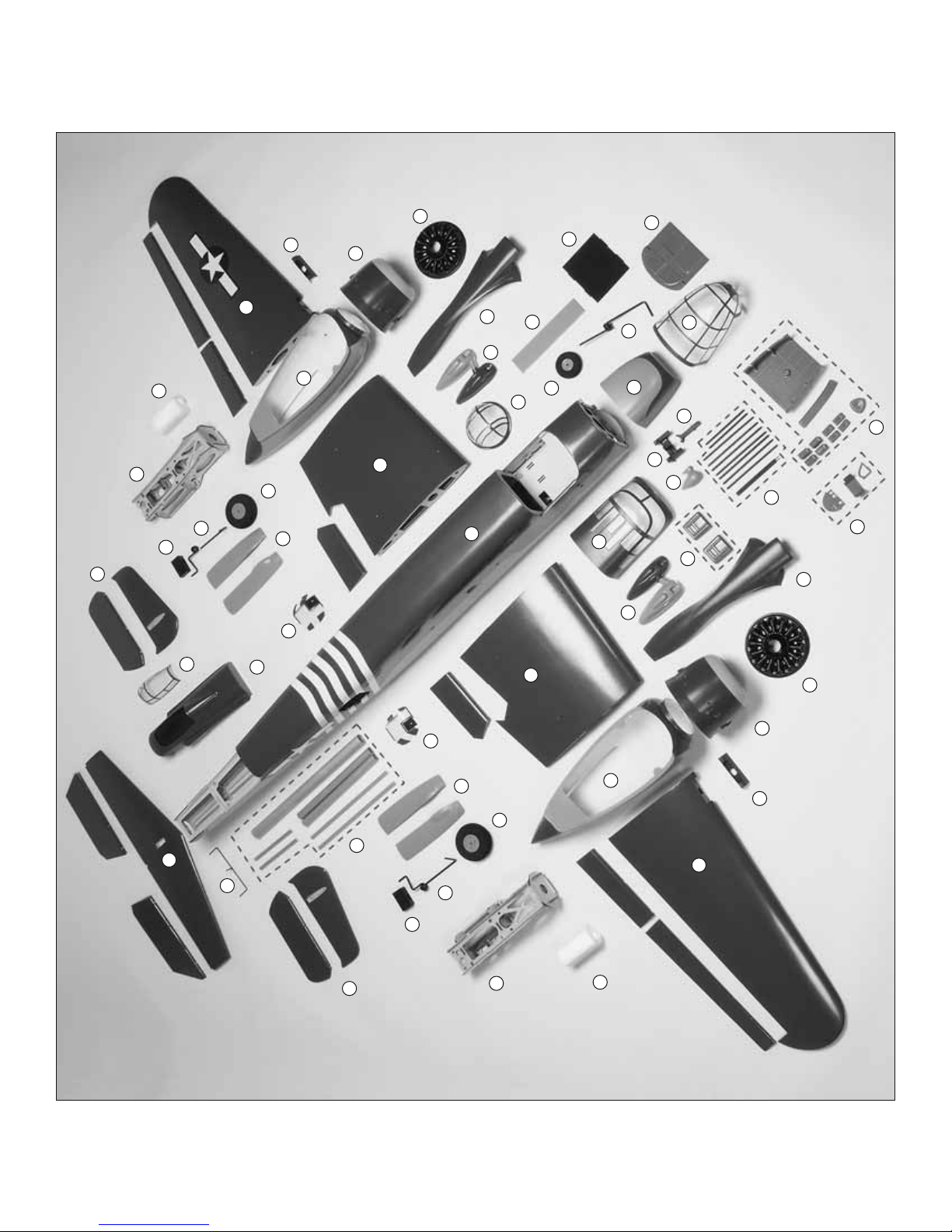
22. Top turret tandem machine guns
23. Nose-gunner machine gun
24. Top machine gun turret canopy
25. R&L side gun packs
26. Nose gear door
27. Nose gear wire
28. 2-5/8" [68mm] nose wheel
29. (7) 6-1/8" [155mm] machine gun barrels (1-nose
TOPA1701 Fuselage Set
TOPA1702 Tail Set (Fins and Stabilizers)
TOPA1703 Left Engine Nacelle Assembly
TOPA1704 Right Engine Nacelle Assembly
TOPA1706 Cowl
threaded inserts
30. Cockpit fl oor (painted fl at black)
31. R&L oil cooler air scoops
32. R&L waist gun windows
TOPA1707 Dummy Engine
TOPA1708 Tail-gunner Cabin
TOPA1709 Gunner Windows
TOPA1710 Wing Tubes
TOPA1711 Landing Gear Set
TOPA1712 Landing Gear Doors (All)
TOPA1713 Cockpit Windscreen
TOPA1714 Cockpit Interior
TOPA1715 Nose-Gunner Window Assembly
TOPA1716 Nose-Gunner Cabin
305mm forward and aft main wing tubes (2, one
end threaded w/nylon inserts), 22 x 295mm outer
panel wing tubes (2), 10 x 150mm outer panel
wing tubes (2, one end threaded w/nylon inserts)
33. Molded plastic fi xed main landing gear blocks
34. R & L main landing gear wires
35. (2) 3-7/8" [98mm] main wheels
36. (2) 420cc Fuel tanks w/hardware
37. 30 x 440mm center main wing tube (1), 10 x
38. Elevator joiner wire
TOPA1717 Machine Gun Set (All)
TOPA1718 Fuel Tank
TOPA1719 Propeller Hub
TOPA1720 Decal Set
TOPA1721 Building Stand
ORDERING REPLACEMENT PARTS
To order replacement parts for the Top Flite
B-25J Mitchell ARF, use the order numbers in the
Replacement Parts List that follows. Replacement
parts are available only as listed. Not all parts are
available separately (an aileron cannot be purchased
separately, but is only available with the wing kit).
Replacement parts are not available from Product
Support, but can be purchased from hobby shops
or mail order/Internet order fi rms. Hardware items
(screws, nuts, bolts) are also available from these
outlets. If you need assistance locating a dealer to
purchase parts, visit www.top-fl ite.com and click
on “Where to Buy.” If this kit is missing parts, contact
Product Support.
7
KIT INSPECTION
Before starting to build, inspect the parts to make
sure they are of acceptable quality. If any parts are
missing or are not of acceptable quality, or if you
need assistance with assembly, contact Product
Support. When reporting defective or missing parts,
use the part names exactly as they are written in the
Kit Contents list on this page.
Champaign, IL 61822
Top Flite Product Support:
Telephone: (217) 398-8970
3002 N Apollo Drive Suite 1
Fax: (217) 398-7721
E-mail: airsupport@top-fl ite.com
KIT CONTENTS
servo hatches
1. Fuselage
2. R&L inboard wing panels, inboard fl aps, fl ap
fl ap and aileron servo hatches
3. R&L outboard wing panels, outboard fl aps, ailerons,
4. Horizontal stabilizer, elevators, rudder servo hatches
5. R&L vertical stabilizer, rudders
6. R&L fi berglass nacelle covers
7. Fiberglass engine cowls
8. R&L ply/balsa/hardwood nacelle assembly
9. R&L carburetor intakes
10. Replica engines
11. Main landing gear doors
pad, ammo boxes and tops (4)
12. Fiberglass tail-gunner cabin
13. Tail-gunner canopy
14. Nose-gunner canopy bottom
15. Nose-gunner window
16. Cockpit canopy
17. Nose-gunner cabin fl oor, ammo tray, kneeling
mounting bracket
18. Nose-gunner cabin back
19. Tail-gunner cabin bulkhead, armor plate,
20. Pilot/co-pilot seat backs
21. Fiberglass ADF “football” antenna w/magnets
Page 8
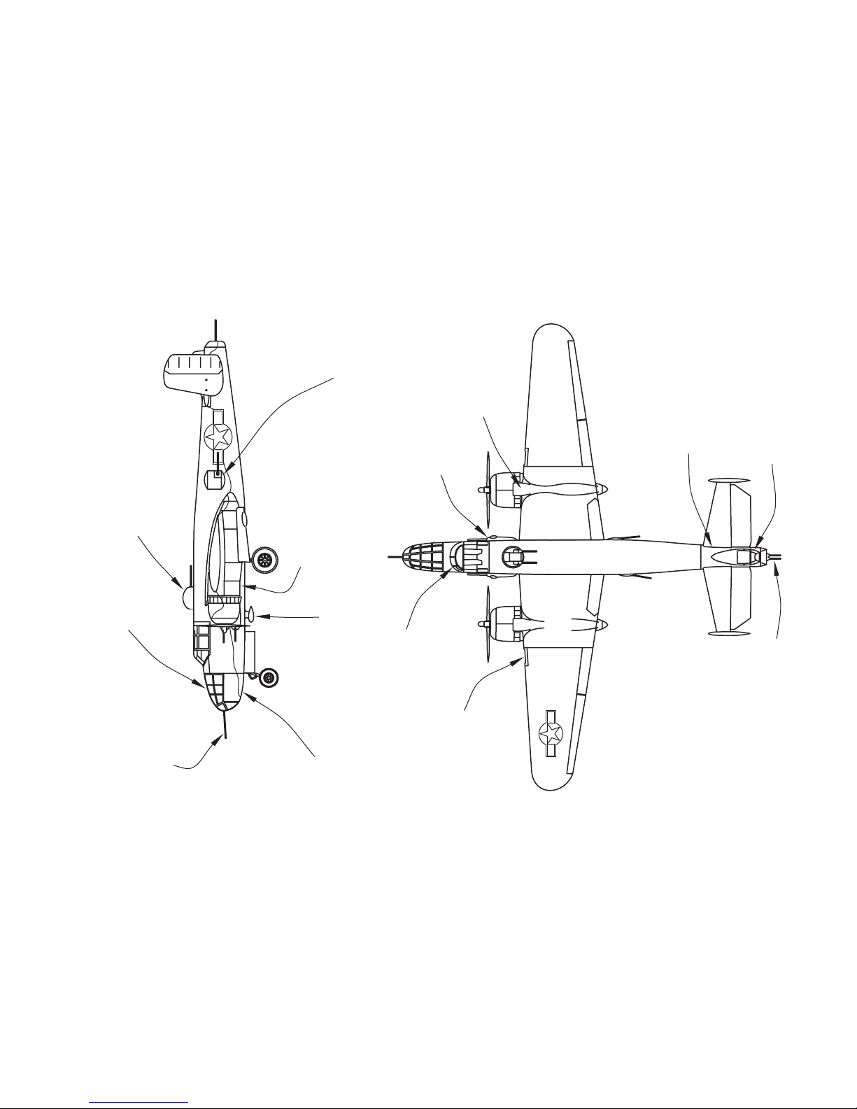
TOP TURRET
WAIST GUN WINDOW/WAIST GUN
SIDE GUN PACKS
CARBURETOR INTAKE
OUTBOARD
WING PANEL
TAIL-GUNNER CABIN
TAIL-GUNNER CANOPY
NOSE-GUNNER CANOPY
THESE ARE THE NAMES OF SOME OF THE SCALE PARTS
NOSE MACHINE GUN
NACELLE COVER
ADF
“FOOTBALL” ANTENNA
NOSE-GUNNER
CANOPY BOTTOM
AIR SCOOP
COCKPIT/COCKPIT CANOPY
OIL COOLER
INBOARD
8
WING PANEL
TAIL GUNS
Page 9
❏ 2. Take out the hinges. Add a small drop of plastic-
compatible oil or a small dab of petroleum jelly to the
pivot point of each hinge. Work the oil into each hinge
by pivoting it back and forth a few times.
epoxy. Use a piece of wire to apply epoxy into the hinge
holes in both inboard wing panels and inboard fl aps.
❏ 3. Mix approximately 1/4 oz. [5cc] of 30-minute
❏ 4. Wipe off any excess epoxy from the outside of
all the hinge holes (using your paper towel squares).
One at a time, apply a thin coating of epoxy to one
9
ASSEMBLE THE WING PANELS
HINGE THE FLAPS AND AILERONS
PREPARATION
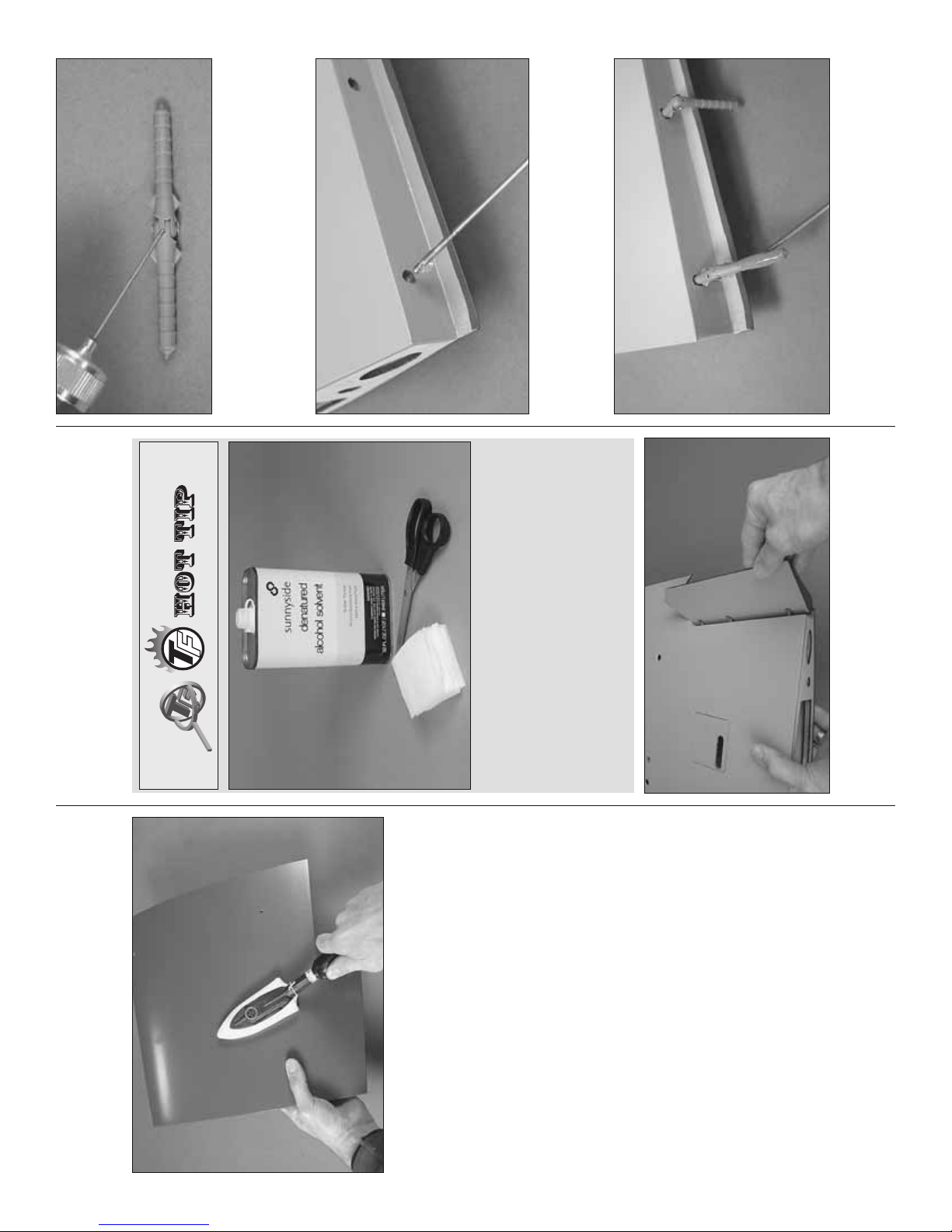
PREPARE THE COVERING
During construction there will be several occasions
where epoxy cleanup will be necessary. Instead
to the airframe. Areas of covering that aren’t bonded
to the wood underneath—even if you don’t see any
wrinkles now—may loosen and form wrinkles later.
The best way to seal down and tighten all the covering
is to use a covering iron with a protective covering
❏ Take time now to thoroughly seal the covering
sock to go over the entire model. Push down on the
of wasting whole paper towels, stack three or four
paper towels on top of each other and cut them
into small squares. This will conserve paper towels
and the little squares are easier to use than whole
paper towels. For epoxy clean up dampen the
squares with denatured alcohol.
iron to bond the covering to the wood. If the covering
bubbles you may be using too much heat or leaving
the iron in one position too long. In some areas,
where the sheeting is soft and there is no supporting
structure underneath, the sheeting may bend inward
making it diffi cult to remove the wrinkles in those
areas. If this happens, use less pressure on the iron
or don’t press down at all. Note: This procedure takes
time. If you don’t feel like going over the entire model
all at once, start with the inboard wing panels fi rst
and do the rest of the parts as you need them.
❏ 1. Test fi t both inboard fl aps to the inboard wing
panels with the large pivot point hinges. Make sure
the fl aps fi t well and pivot smoothly.
Page 10
Note: The four-stroke template is for the O.S. Max .70
Surpass and the two-stroke template is for an O.S.
Max .40 or .50 two-stroke. Since the engine mounts
are adjustable, they should fi t other engines in the
size range, but if you are using engines different than
O.S. the positioning of the mounts may have to be
rotated slightly to align the muffl er with the muffl er
cutout in the fi berglass nacelle cover. If this is the
case, you’ll have to mount your engine to the mount
❏ ❏ 2. After the epoxy from the previous step has
hardened, use four 1/4-20 x 2" [50mm] nylon bolts
(indicated by the arrows in the photo) to mount the
left engine nacelle to the bottom of the left inboard
wing panel.
before marking the holes in the fi rewall. Then, place
the nacelle cover over the nacelle on the wing panel
and position the mount (with the engine) so the
muffl er fi ts in the muffl er cutout.
❏ ❏ 4. Once the engine mount holes have been
marked, drill 5/32" [4mm] holes through the fi rewall
at each mark. Remove the template. Push 4-40 blind
nuts into the holes in the back of the fi rewall—if
necessary, trim away any plywood that interferes with
the blind nuts.
❏ ❏ 3. Read the note following this step. Then, cut
out the left Engine Mounting Template (since we’re
doing the left nacelle fi rst) from the back of the manual
for the type of engine you will be using—two-stroke
10
or four-stroke. Use tape or spray adhesive to hold the
template to the fi rewall. Then use a sharpened piece
of wire or a large T-pin to mark the center of the holes
in the template into the fi rewall.
side of each hinge. Then, insert the hinges into the
wing. When all the hinges are in, working quickly,
coat the other end of the hinges with epoxy. Then,
join both fl aps. Do your best to wipe away any excess
epoxy. Move the fl aps up and down several times to
align all the hinges. Set the wing panels aside and
allow the epoxy to harden.
❏ 6. Join the outboard fl aps and ailerons to the outboard
wing panels the same way using fresh batches of
epoxy. Note that the ailerons use small hinges.
❏ 7. After the epoxy on all the hinges has hardened,
move the fl aps and ailerons up and down several
times to get them moving smoothly and easily.
We’ll install the servos and hook up the fl aps and
ailerons later.
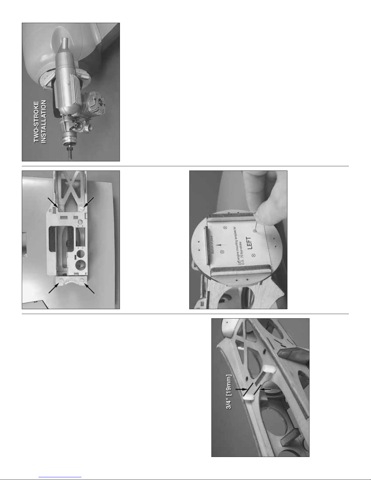
MOUNT THE ENGINES
❏ 1. Use medium CA or epoxy to glue two 8 x 30mm
grooved nylon alignment pegs into the holes in
each engine nacelle. Be certain the peg indicated
protrudes above the base of the nacelle approximately
3/4" [19mm].
Page 11
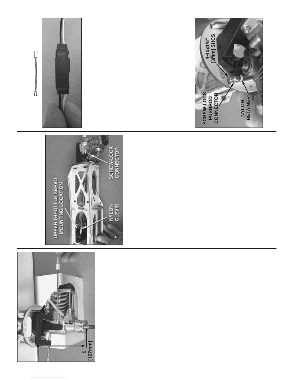
6" [150 mm]
SERVO EXTENSION
❏ ❏ 2. Connect a 6" [150mm] servo extension to the
throttle servo. (There are diagrams on pages 48-49
that show all the servo extensions that were used.) Cut
a piece of the 3/8" x 3" [10 x 75mm] black heat shrink
tubing in half and fi t it over the connection between
the servo wire and the extension. Carefully shrink the
tubing with heat from a heat gun or a lighter.
❏ ❏ 3. Place the throttle servo in the mounting
location you will be using—if using the upper throttle
servo mounting location shown, the nacelle will have
to be removed from the wing. Use the mounting holes
in the servo as a guide to drill 1/16" [1.6mm] holes for
the servo mounting screws that came with the servo.
Temporarily mount the servo with the screws. Then,
remove the screws and servo. Add a few drops of
thin CA to each screw hole, allow to harden, and then
remount the servo.
❏ ❏ 4. Hook up throttle using a 2-56 x 17-1/2"
[445mm] pushrod and a nylon clevis on the servo
11
HOOK UP THE THROTTLE AND
INSTALL THE FUEL TANK
Refer to this photo while hooking up the throttle.
The throttle servo may be mounted in either of two
locations depending on the location of the carburetor
arm on your engine. For most two-stroke engines, it
will be easiest to mount the throttle servo in the lower
location (the location in the bottom of the nacelle next
to the landing gear mount). For some four-stroke
engines (such as the O.S. Max .70 illustrated in this
manual), it will be easiest to mount the throttle in
the upper location (as shown in the photo). If using
the O.S. Max .70, the carburetor will also have to be
reversed to position the carburetor arm on the top.
If using the O.S. .70, remove the engine, reverse
the carburetor and carb arm, and then remount the
engine. However you decide to hook up the throttle,
make certain the pushrod will not interfere with the fuel
tank when it is in position later (you could temporarily
fi t the fuel tank while working on the throttle).
™
❏ ❏ 5. Loosely mount the engine mount to the fi rewall
with 4-40 x 3/4" [19mm] socket-head cap screws
(SHCS) and #4 fl at washers. Adjust the mount to fi t
your engine. Tighten the screws to pull the blind nuts all
the way into the back of the fi rewall. Temporarily clamp
Engine Mount Hole Locator (GPMR8130) or another
method to mark the holes in the mount for the engine
mounting screws. NOTE: The 3/4" [19mm] screws
the engine to the mount so the front of the drive washer
will be 5" [127mm] from fi rewall. Use a Dead Center
holding the mount to the fi rewall are intentionally short
so they do not cut into the front of the fuel tank. Later,
when mounting the engine for the fi nal time, you will
be instructed to add threadlocker to the threads of the
screws so they do not come loose.
❏ ❏ 6. Remove the engine from the mount and take
the mount off the fi rewall. Add a few drops of thin
CA to the edges of the blind nuts in the back of the
❏ ❏ 7. Drill #29 holes at the marks you made in the
engine mount halves for mounting the engine. Tap 4-
fi rewall so they won’t come out.
40 threads into the holes. Remount the mount to the
❏ ❏ 1. Center the throttle servo by temporarily
connecting it to the receiver with a battery and turning
on the radio with the throttle trim on the transmitter
fi rewall and mount the engine to the mount with four
4-40 x 3/4" [19mm] SHCS, #4 lock washers and #4
❏ 8. Mount the other engine to the right nacelle the
fl at washers.
centered. Cut off the unused servo arms so there is
one arm remaining.
same way. Make sure you use the right engine mounting
template for marking the holes in the fi rewall.
Page 12
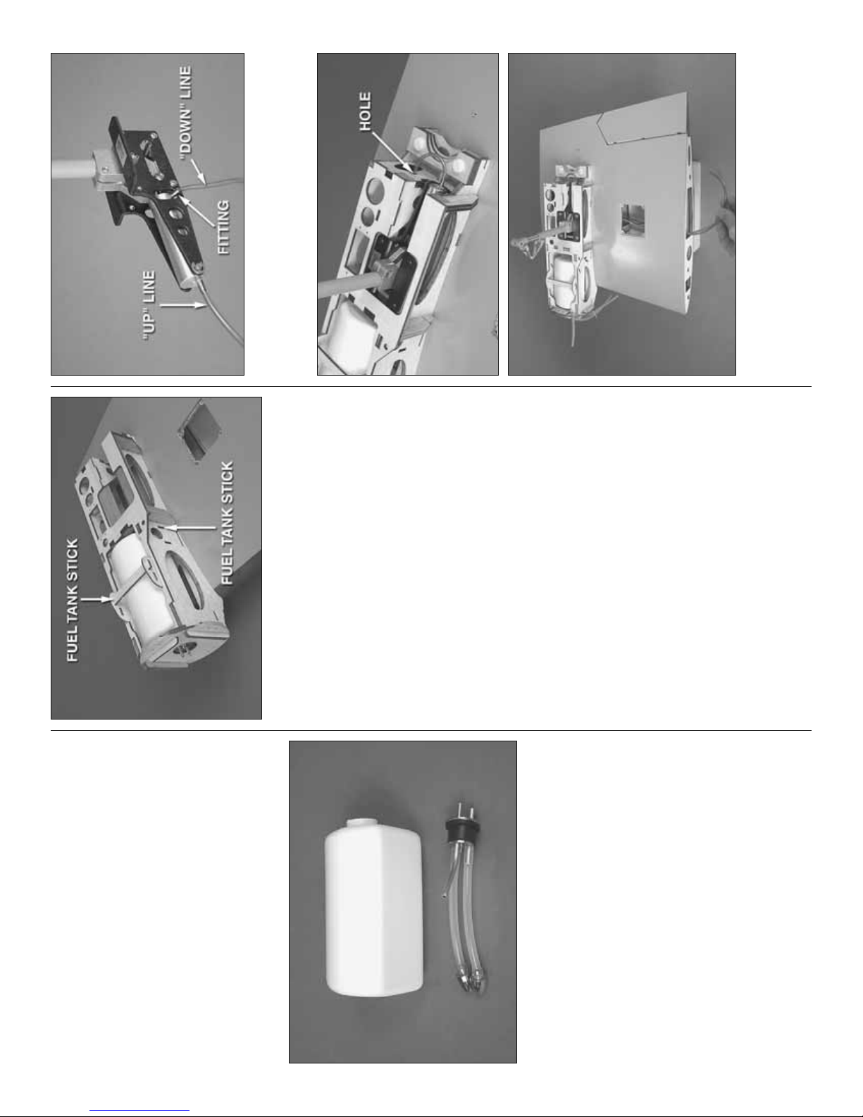
❏ ❏ 2. Connect the lines to the air cylinder. Rotate
the fi tting on the down line as shown so it will be
easier to fi t the gear between the rails.
❏ ❏ 8. Mount the left nacelle to the wing with the nylon
bolts. Fit the fuel tank into the nacelle. Then, install and
glue two 3/8" x 3-1/16" [10 x 78mm] plywood fuel tank
sticks from the laser-cut plywood sheet into the slots
❏ ❏ 3. Install the retract and guide the air lines through
the hole in the bottom of the panel, past the fl ap servo
hatch and out root end of the panel—note that the up line
goes through the hole in the back of the nacelle fi rst.
12
to hold the fuel tank in position. Note: Even though fuel
lines appear in a few of the following photos, there’s
no need to connect them until later after the cowl has
been mounted—the manual will instruct you later.
❏ 9. Return to step 1 and mount the engine, hook up
the throttle and install the fuel tank in the right nacelle
the same way.
MOUNT THE MAIN LANDING GEAR
RETRACT INSTALLATION
(If not mounting retracts, skip to “Fixed Gear
Installation” on the next page.)
Same as we’ve been doing so far, start with the left,
inboard wing panel.
❏ ❏ 1. Determine which color of air line you will be
using for the “up” line and which color you will be
using for the “down” line—the up line connects to the
fi tting on the back end of the air cylinder and the down
line connects to the fi tting on the front of the cylinder
that comes out of the side. Cut the up line to a length
of 21" [530mm] and cut the down line to a length of
18" [460mm].
fi berglass nacelle cover and mounting the landing
gear, it will be easier to have the engine out of the
way. Remove the engine mount from the fi rewall and
end and a brass screw-lock connector with a nylon
retainer and a 4-40 x 1/8" [3mm] socket-head cap
screw (SHCS) on the carburetor arm. Cut a slot in the
fi rewall for the throttle pushrod. Bend the pushrod as
necessary to connect to the carburetor arm.
❏ ❏ 6. For installing the fuel tank, mounting the
set the engine aside.
is recommended—one for the vent/pressure line going
to the muffl er, one for fuel pickup to the carburetor and
a third line for fueling/defueling. This setup will allow
fueling and defueling without having to disconnect
any lines from the carburetor and without having to
turn the model upside-down. To set up the fuel tank
this way, cut two of the aluminum tubes to a length of
1-3/8" [35mm] and leave the other, longer tube as-is.
Assemble the stopper assembly with the aluminum
tubes, bend the longer vent tube upward so it will be
at the top of the tank, and then cut the silicone lines
❏ ❏ 7. Assemble both fuel tanks—a three-line setup
to the correct length so the clunks will not contact the
rear of the tank. Connect the lines to the tubes in the
stopper and fi t the stopper into the tank and tighten
the screw. Make sure the clunks do not contact the
rear of the tank; otherwise, they could get stuck.
Page 13
Engine Mount
™
MOUNT THE FIBERGLASS NACELLE COVERS
Refer to this photo while mounting the landing gear.
❏ ❏ 1. If you haven’t done so already, remove the left
engine from the engine mount so the nacelle cover
will fi t over the nacelle. Place the left fi berglass nacelle
cover over the nacelle on the wing. Use a pushrod
sharpened on the end or a Dead Center
Hole Locator to mark the location of the three mounting
screws for the nacelle cover into the bottom of the wing.
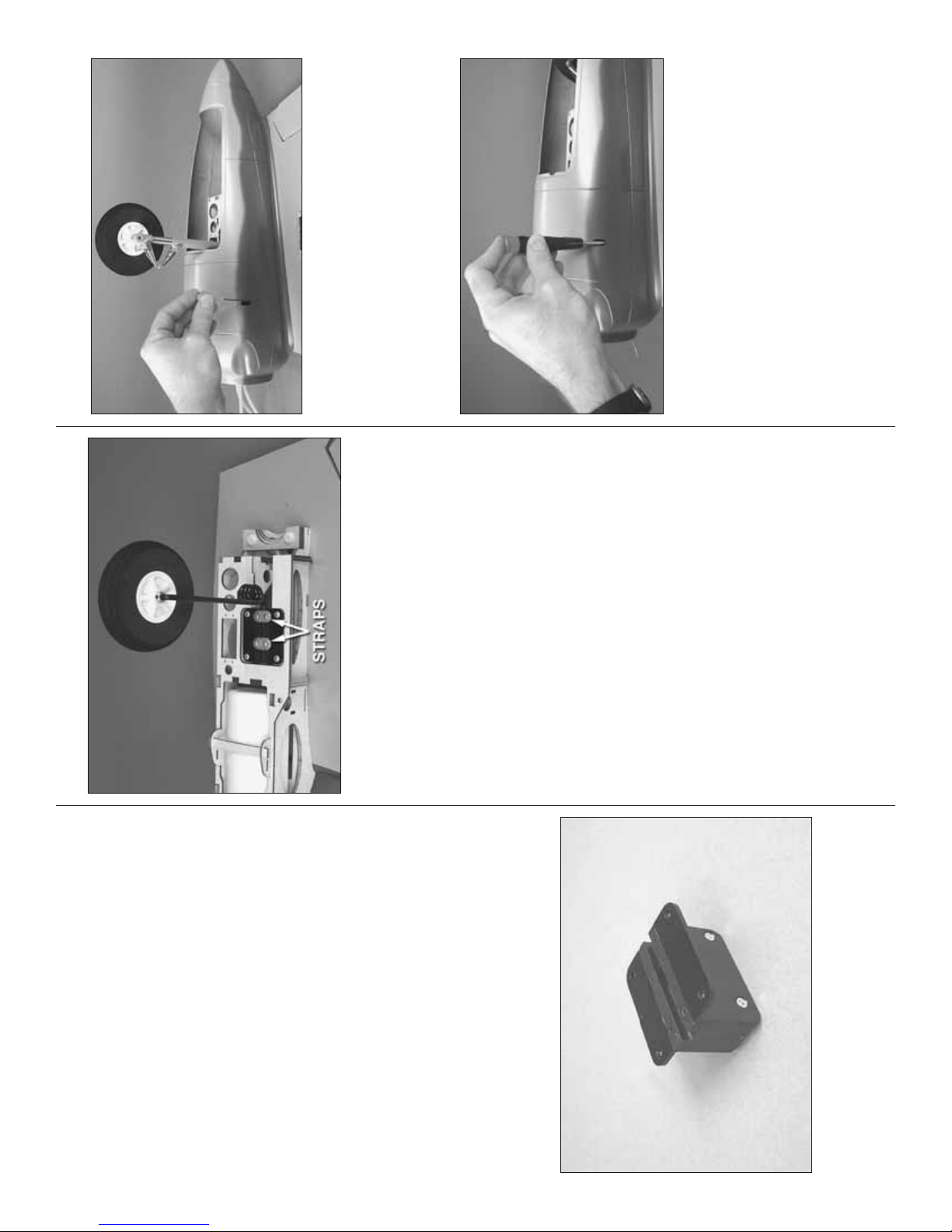
❏ ❏ 2. Center the landing gear mount on the
mounting rails. Then, drill four 7/64" [2.8mm] holes for
the mounting screws. Mount the landing gear mount
with four #6 x 1/2" [13mm] Phillips screws.
❏ ❏ 3. Mount the left, main landing gear wire into the
landing gear mount using two nylon straps and four #4
x 1/2" [13mm] screws. Mount one of the main wheels
to the landing gear wire with two 5mm wheel collars
and 6-32 set screws with threadlocker on the threads.
❏ 4. Mount the other landing gear to the right inboard
❏ ❏ 2. Remove the nacelle cover. Drill 3/32" [2.4mm]
holes into the wing at the marks. Enlarge the holes
in the plywood mounting tabs in the nacelle cover
only with a 1/8" [3.2mm] drill. Use a long #1 Phillips
wing panel the same way. Add a drop of oil to both
sides of the wheels where they contact the collars.
screwdriver to temporarily mount the nacelle cover to
the wing with four #4 x 5/8" [16mm] Phillips screws,
#4 fl at washers and #4 lock washers.
❏ ❏ 3. Remove the nacelle cover. Add a few drops
of thin CA to each of the screw holes for the nacelle
cover mounting screws. Allow the CA to harden before
mounting the nacelle cover back to the wing.
13
❏ ❏ 4. Holding the retract centered in the rails with
the strut retracted so it will be out of the way, drill four
7/64" [2.8mm] holes for the mounting screws. Mount
❏ ❏ 5. Use a rotary tool with a fi ber-reinforced cutoff
the retract with four #6 x 1/2" [13mm] Phillips screws.
wheel to cut the one of the main landing gear axles
that came with the retracts to the correct length. File
a fl at spot on the axle for the set screw that mounts
the axle to the strut. Mount the wheel with a drop of
threadlocker on the set screw. Add a drop of oil to
❏ 6. Mount the other retract to the right inboard wing
both sides of the wheel at the strut and the axle.
panel the same way.
FIXED GEAR INSTALLATION
❏ ❏ 1. Assemble one of the landing gear mounts
by using eight 3 x 12mm fl at-head Phillips screws to
mount an aluminum mounting bracket to each side of
one of the molded plastic main landing gear blocks.
Page 14
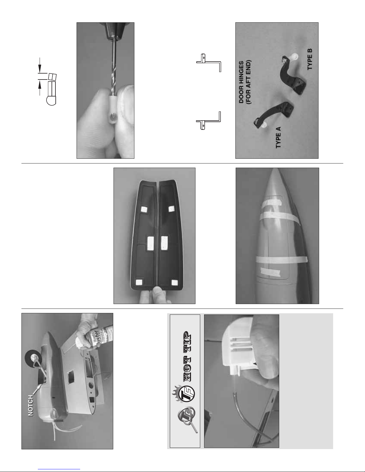
1/8"
[3mm]
BALL LINKS FOR REAR DOOR HINGES
DOOR HINGES
TYPE A TYPE B
(These are the hinges that are glued onto the gear doors.)
❏ ❏ 5. Use a single-edge razor blade to cut 1/8" [3mm]
off two nylon ball links—do your best to cut the ends
square. Drill the holes for the screw in the ball links the
rest of the way through with a 5/64" [2mm] drill bit.
❏ ❏ 6. Mount one of the ball links you just cut off
to a “TYPE A” door hinge and mount the other ball
link you just cut off to a “TYPE B” door hinge with a
14
MOUNT THE MAIN LANDING GEAR DOORS
(FOR RETRACTS ONLY)
If using fi xed landing gear, skip to “Mount the
Cowl” on page 19.
❏ ❏ 1. Remove the nacelle covers from the wing panels.
❏ ❏ 2. Look at the photos on page 15 to see where
the door hinges are mounted. Use coarse sandpaper
to roughen the inside of the left nacelle cover where
the landing gear door hinges will go.
❏ ❏ 4. Re-mount the nacelle cover to the wing.
If you’ve mounted retracts, read the Hot Tip that
follows. Then, cycle the gear a few times to make
sure everything works. (If necessary, use a sanding
drum to enlarge the half-round notch at the front of
❏ ❏ 3. Use a hobby knife to scrape away the black
paint from the recesses inside one set of fi berglass
main landing gear doors so the glue will adhere for
the door hinges.
The landing gear can be easily cycled with a can
of compressed air such as a Hobbico Duster. Cut
two 1" [25mm] pieces from the tube that comes with
the opening in the nacelle cover.)
the can. Fit the tubes into the ends of both air lines
❏ ❏ 4. Place the doors on the left nacelle cover. Use
masking tape to tape the doors together, and then
tape them to the nacelle cover.
coming from the wing that are connected to the
gear. Connect one tube to the Duster to extend the
gear and connect the other tube to retract the gear.
❏ 5. Mount the right nacelle cover the same way.
Page 15

s
NACELLE COVER
GEAR DOOR
As best as you can, get the bases of the hinge
to lay flat on the door and on the nacelle cover.
Make sure the glue press up and fills the holes
of the mounts.
of each hinge base so glue will adhere. Test fi t the hinge
assemblies to the doors and nacelles—each hinge
assembly should be in the location and orientation
shown. If necessary, adjust the length of any of the
ball links by cutting them shorter so the hinges will rest
❏ ❏ 10. Use coarse sandpaper to roughen the bottom
fl at, or nearly fl at, on the doors and nacelle.
❏ ❏ 11. Use epoxy mixed with milled fi berglass or
micro balloons to glue each door hinge to the doors.
After the epoxy has hardened glue each nacelle
hinge to the nacelle.
❏ ❏ 12. After the epoxy on the door hinges has
hardened, remove the masking tape and open
the doors.
❏ 13. Hinge the doors to the other nacelle the
same way.
15
1/16"
[1.5mm]
BALL LINKS FOR FRONT DOOR HINGES
2-56 x 3/8" [9.5mm] screw, #2 lock washer and #2
fl at washer. These hinges will go on the aft end of the
gear doors.
❏ ❏ 7. Cut 1/16" [1.5mm] from two more nylon ball
❏ ❏ 9. Snap the ball link balls of the nacelle hinges
onto the ball links on the door hinges as shown.
links. Mount each ball link to another TYPE A and
TYPE B door hinge. These door hinges will be for the
front of the gear doors.
❏ ❏ 8. Prepare two “TYPE A” nacelle hinges and
two “TYPE B” nacelle hinges by mounting an 0-80
ball link ball in the bottom hole of each hinge with an
0-80 nut and a drop of threadlocker on the threads.
Page 16
3/8"
3/8"
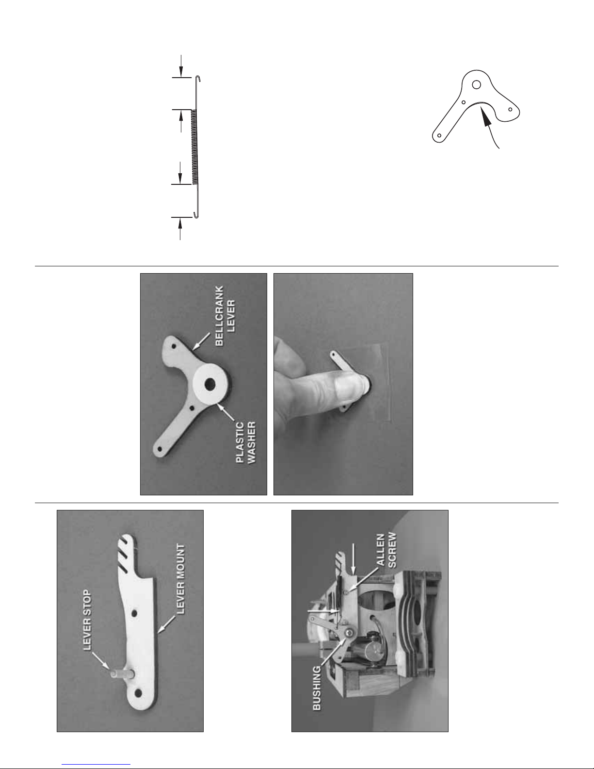
❏ ❏ 6. Remount the lever mount to the nacelle with
the #2 x 3/8" [9.5mm] button-head screw. Fit a brass
bushing into the plywood bellcrank lever as shown.
Mount the bellcrank lever to the lever mount and the
nacelle with the #4 x 5/8" [16mm] screw. Tighten the
screw as much as possible without causing the lever
to bind.
[10mm]
[10mm]
❏ ❏ 7. Bend a hook on each end of the spring where
shown and cut off the excess wire. Connect the spring
to the bellcrank lever and the lever mount as shown—
there should be just enough tension in the spring to
pull the lever to the lever stop. Later, if necessary,
the spring tension can be adjusted by using another
notch in the lever mount. Move the bellcrank up and
down to make sure it moves smoothly with a small
amount of resistance from the spring. Make any
adjustments necessary.
❏ ❏ 8. Mount the nacelle cover with the doors
attached to the wing panel. Note: If the doors ever
require removal for repairs/servicing, do not pop off
the ball links. Instead, unscrew the 2-56 screws from
the ball links.
If necessary, trim
the lever here.
❏ ❏ 9. Test the “action” of the landing gear and
the lever mechanism by operating the system with
❏ ❏ 3. Use the other hole in the lever mount as a
guide to drill a 3/32" [2.4mm] hole into the nacelle for
the #4 screw that will hold in the bellcrank.
❏ ❏ 4. Remove the lever mount. Temporarily thread
a #4 x 5/8" [16mm] Phillips screw into the larger hole
you drilled. Remove the screw. Add a few drops of
thin CA to both screw holes and allow to harden.
❏ ❏ 5. Use medium CA to glue a 5mm I.D. x 12mm
O.D. thin, plastic washer to the front surface of the
plywood bellcrank lever. (Six washers are included in
the kit—two are for the levers on the main landing
gear doors, one is for the lever on the nose landing
gear and three are left over for spares.) The easiest
16
way to glue on the washer is to pick it up with a hobby
knife, apply a thin fi lm of thin CA to it and place it
on the lever centered over the hole. Then turn the
lever over and press down over a piece of plastic fi lm
(from a sandwich bag or leftover MonoKote backing)
or wax paper.
HOOK UP THE MAIN LANDING GEAR DOORS
❏ ❏ 1. Glue a 1/8" x 1/2" [3 x 15mm] hardwood
dowel lever stop into one of the lever mounts as
shown. The end of the stop should be fl ush with the
other side of the mount.
Use this photo for the next 8 steps.
❏ ❏ 2. Hold the lever mount on the back of the
nacelle as shown—the outer edge of the mount
should be even with the side of the nacelle and the
top of the mount should be even with the bottom edge
of the nacelle (where indicated by the arrows). Using
the small hole in the right side of the lever mount as
a guide, drill a 1/16" [1.6mm] hole into the nacelle.
Mount the lever mount to the nacelle with a #2 x 3/8"
[9.5mm] button-head Allen screw.
Page 17

❏ ❏ 14. Connect the outboard pushrod to the
bellcrank lever. Use medium CA to glue the control
horn to the door in alignment with the lever. Retract
and extend the gear by hand, adjusting the length
of the pushrod so the door will close when the gear
is retracted. Retract and extend the gear with air
pressure, making sure it works. Make sure the rear
hinge on the outboard door isn’t rubbing against the
wheel when the door is closed. If it is, you can use
a hobby knife to carefully trim down the other side
of the wheel around the hole for the axle to shift the
wheel over, or remount the rear of the nacelle cover
slightly over to the side—either of which will give the
❏ ❏ 13. The same as was done on the ball links for the
door hinges, cut 1/8" [3mm] from the end of two nylon
clevises. Make the outboard door pushrod using
the short clevises and complete the inboard pushrod
using another regular clevis and the hardware shown.
Do not install the nylon retainer on the brass screw-
lock pushrod connector until instructed to do so later.
hinge and wheel more clearance.
about 1/2" [13mm] from the end as shown.
❏ ❏ 15. Make one more bend in the inboard pushrod
17
mounting base of two small nylon control horns
compressed air. Make sure the gear locks at both
ends—up and down. It may be necessary to slightly
trim the lever to allow the landing gear strut to move
freely. If necessary, remove the lever, trim, reinstall
and test.
(shown in the photo to the right).
❏ ❏ 10. Use coarse sandpaper to roughen the
2-1/2"
[65mm]
3/8"
[10mm]
INBOARD DOOR PUSHROD
INBOARD DOOR PUSHROD
part of the threaded end and part of the unthreaded
end of a 4" [100mm] pushrod as shown above.
❏ ❏ 11. Make an inboard door pushrod fi rst by cutting
pushrod as shown.
❏ ❏ 12. Use the sketch as a template to bend the
Page 18

Retract and Door Adjustments:
If the retracts don’t retract or extend all the way or
if the doors don’t fully close, following is a list of
possible problems and solutions:
❏ ❏ 17. Temporarily disconnect the outboard pushrod
from the bellcrank lever. Retract the gear by hand
and close the door. With the door closed, lock the
pushrod to the screw-lock connector with a 4-40 x 1/8"
[3mm] SHCS.
Shorten the pushrods in small increments.
❏ A. One or both pushrods may be too long.
❏ ❏ 18. Extend the gear and open the door by
❏ B. One or both pushrods may be too short
not allowing the gear to retract fully. Lengthen
the pushrods.
hand. Reconnect the outboard pushrod and cycle
the gear with compressed air—both with the nacelle
upside-down and upright. Make sure both doors
open and close and that the retract locks in both the
retracted and extend positions. Make any necessary
adjustments as described below to get the gear and
❏ C. There may be too much or not enough
tension in the spring. Move the spring to a different
setting on the lever mount.
❏ D. There may be too much friction in the retract
unit, not allowing it to operate freely and all the
way. Lightly oil moving parts in the retract unit.
doors operating correctly.
❏ 19. Mount and hook up the doors on the right
inboard wing panel the same way. Keep the left panel
nearby so it can be used as a reference.
❏ 20. Once you get both doors operating correctly
❏ E. Some of the parts in the door mechanism
may be binding. Isolate moving parts and fi nd
out if any are too tight (ball links on ball link balls,
clevises, screw-lock pushrod connector in inboard
door, screw holding in bellcrank lever.)
❏ F. The clevis on the inboard pushrod that is
connected to the lever may be interfering with the
and reliably, snap a nylon retainer onto both screw-
lock connectors on the horns on the inboard doors.
inboard pushrod. Bend the inboard pushrod as
necessary to clear the clevis on the other side of
the lever.
❏ G. There may not be enough air pressure to fully
retract the gear—compressed air cans advertised
as “dusters” typically put out approximately 90-
100psi, but your can may be too low. 60-80psi
should be adequate for fully retracting the gear—
less for extending gear.
❏ H. You may be extending or retracting the gear
too slowly. A little momentum and a mild “slam”
will help the strut and doors extend and retract all
the way.
18
❏ ❏ 16. Connect the inboard pushrod to the other
end of the plywood lever. Use medium CA to glue
the horn to the inboard door. In the top-view photo,
note how the horn is slightly ahead of the lever so the
pushrods will not interfere when the door closes.
Page 19

❏ ❏ 6. Mount the nacelle cover to the wing panel.
Use two 4-40 x 3/8" [9.5mm] Phillips screws, #4 lock
❏ ❏ 4. Use a 4-40 x 3/8" [9.5mm] Phillips screw and
two #4 washers to pull 4-40 blind nuts into the back of
washers and fl at washers to mount each cowl mounting
tab to the front of the fi rewall—the short “B” tabs go on
the sides of the fi rewall and the long “A” tabs go on the
each hole just drilled in the fi rewall. Use epoxy to glue
in the blind nuts as they go in or use a few drops of
thin or medium CA to glue in the blind nuts after they
top and bottom of the fi rewall. The “A” tab with the blind
are all the way in.
nut goes on top of the wing and the blind nut goes
toward the back. Note: Do not tighten the screws all
the way so the tabs will be allowed to “fl oat.”
❏ ❏ 7. Mount three more 4-40 blind nuts into the
three large holes in one side of one of the cowl
rings and glue them in—note that one of the holes
is smaller than the other three—do not mount a blind
nut into that small hole.
19
❏ ❏ 5. Note that there are two different plywood
cowl mounting tabs—long ones (“A”) and short
ones (“B”). One of the longer, “A” tabs has a larger
hole in the top. Press a 4-40 blind nut into the larger
hole of that “A” tab.
MOUNT THE COWL
❏ ❏ 1. Take a few minutes to study how the cowl
is mounted in the following photos. The cowl is
mounted via a cowl ring which is permanently glued
in the cowl. The cowl ring is attached to removable
cowl mounting tabs with 4-40 x 1/2" SHCS—three
of the cowl mounting screws are accessible from
behind the cowl and the fourth one on the top of the
cowl is accessible through the front. (Otherwise, the
carburetor intake would have to be removed just to
remove the cowl.) Each cowl mounting tab is attached
to the fi rewall with two 4-40 x 3/8" [9.5mm] Phillips
screws and blind nuts. The cowl mounting tabs are
removable so that the fi berglass nacelle cover can be
removed to access components in the nacelle.
❏ ❏ 2. Disconnect the retract door pushrods and remove
the nacelle cover from the left, inboard wing panel.
at the eight precut marks for the cowl mounting tabs.
IMPORTANT!: Use care NOT to drill into the fuel tank
❏ ❏ 3. Drill 5/32" [4mm] holes through the fi rewall
when drilling through the bottom two holes!
Page 20

fi tting the cowl later.
III. A 3/32" ball driver will be indispensable when
IV. Curved and fl at hobby fi les.
Tools For Cutting Fiberglass
plywood with sandpaper glued on.
carbide cutter is best for making initial cuts.
Abrasive drum sanders work well for “fi ne-
tuning.”
V. Various cutting bits for your rotary tool—the
exhaust fan that will draw fi berglass dust away is
best. If possible, cutting fi berglass outdoors may
Always wear eye and respiratory protection.
There are several fi berglass parts on this model. A
few of them will require cutting and trimming to end up
with the best fi t. Follow these warnings and use the
suggested tools for working safely with fi berglass.
A. Do not be casual when working with fi berglass.
B. Work in a well-ventilated area—working under an
also be a good idea.
VI. A small sanding board made from a piece of
C. Wear a long-sleeve shirt when cutting fi berglass.
smooth rough edges.
VII. Small sheets of medium-grit sandpaper to
protection is recommended.
D. If using a high-speed rotary tool, hearing
❏ ❏ 11. Retrieve your fi berglass cutting tools and
safety equipment. Cut one of the fi berglass engine
cowls to fi t over the engine—it doesn’t matter which
of the two cowls you choose because they are both
the same. Cutting the hole is basically a trial-and-error
process where you cut-and-fi t and cut-and-fi t the cowl
until it goes over the engine. If using a 4-stroke, the
cowl fi tting procedure will be easier if the valve cover
is temporarily removed. If using a 2-stroke the cowl
will be easier to fi t if the head is temporarily removed.
This will allow the cowl to fi t without having to fi nalize
the exact size, shape and location of the cutout until
after the cowl has been permanently mounted. Start
by trying to fi t the cowl over the engine as far as it
will go. Use a fi ne-point felt-tip pen or a lead pencil
to mark the inside of the cowl in the approximate
location where the engine will stick out.
20
ink can be removed with a paper towel and
denatured alcohol.)
E. Following are the best tools for cutting fi berglass:
I. A rotary tool.
II. A fi ne-point, felt-tip pen for marking. (Afterward,
❏ ❏ 8. Mount the cowl ring to the cowl mounting
tabs with four 4-40 x 1/2" SHCS, #4 lock washers and
#4 fl at washers. Note that the top screw goes in from
the front, but the other three go in through the back. A
3/32" ball end hex wrench (GPMR8002) is virtually a
must from here on out. Once the cowl ring has been
fastened to all the tabs, go ahead and tighten up the
screws holding the tabs to the fi rewall.
the muffl er. Trim the cowl ring as necessary until you
can get the muffl er to fi t.
❏ ❏ 9. Mount the engine mount and engine without
ready to start cutting fi berglass and read the Hot Tip
❏ ❏ 10. Remove the muffl er from the engine. Get
below that lists recommended tools, working tips and
safety warnings for cutting fi berglass.
Page 21

position, place a propeller on the engine and position
the cowl so it looks best—due to the out thrust and
down thrust of the engine, a compromise will have to
be made between centering the propeller in the cowl
and aligning the cowl with the nacelle cover—if the
propeller was centered in the front of the cowl, the
outward and downward angle of the cowl wouldn’t
look right. If the cowl were aligned perfectly with the
nacelle the propeller would be too far off center in the
cowl. Look at the cowl from different angles and get it
positioned where it looks best.
joiner tubes—no need to use the screws to secure
the tubes in the wing panel at this time. Counter-
weight made from bags of shot or something similar
will be needed on the tubes coming out of the right
side of the fuselage.
❏ ❏ 15. Use medium-grit sandpaper to roughen the
inside of the cowl all the way around where the cowl
ring will go.
❏ ❏ 18. Once satisfi ed with the position of the cowl,
use medium CA and accelerator to tack glue the cowl
to the cowl ring in about four or six different spots.
❏ ❏ 19. Without accidentally breaking the cowl ring
free from the cowl, use your 3/32" ball-end hex wrench
to loosen the screws and carefully remove the cowl
from the nacelle. Use 30-minute epoxy mixed with
milled fi berglass or microballoons to securely glue
the cowl ring to the cowl with a small fi llet all the way
around both sides.
❏ ❏ 16. Test fi t the left, fi berglass carburetor
intake to the top of the wing. Make any adjustments
necessary for a good fi t. Then, drill 1/16" [1.6mm] holes
into the wing through the holes in the intake. Mount
the carburetor intake to the wing with eight #2 x 3/8"
[9.5mm] button-head Allen screws.
❏ ❏ 20. Cut a small, rounded slot in the top of the
cowl to accommodate the ball-end hex wrench to
access the top cowl mounting screw. Access through
this slot will be necessary after the replica engine has
been installed.
21
❏ ❏ 17. Trim the top of the cowl as necessary to
accommodate the intake. With the intake and cowl in
❏ ❏ 12. Using the marks inside the cowl as a guide,
use your rotary tool with a carbide cutter to cut a
rough, undersize starter hole in the cowl. See if
you can fi t the cowl over the engine. Continue fi tting
and cutting the cowl until you can get it into position
over the head and the cowl ring—cut only as much as
needed to get the cowl over the engine—fi nal cutting
and trimming will be done later after the cowl and
cowl ring have been permanently joined.
place the fuselage in the building stand. Then, fi t the
❏ ❏ 13. If you haven’t yet done so, assemble the
building stand that came with this kit by using epoxy
or white glue to glue the plastic tubes into the foam
cradles. Apply the foam cushion strips to the front and
back of both cradles where they support the fuselage.
inboard wing panel to the fuselage with the aluminum
❏ ❏ 14. Once you can get the cowl over the engine,
Page 22

MOUNT THE REPLICA ENGINE
from a balsa block (not supplied) and a 9/32" [7mm]
O.D. K+S brass tube. Sharpen the end of the tube,
and then use it to cut a hole through the balsa block.
Round the top of the block to fi t the inside of the cowl.
Glue a 1/4" [6mm] piece of the brass tube into the
balsa block so it sticks out the rounded side of the
block 1/32" [.5mm].
❏ ❏ 1. Sand all the way around the edge of one of the
replica engines so glue will adhere. Sand the inside of
the cowl where the engine will be glued as well.
❏ ❏ 25. Cut a 9/32" [7mm] hole in the cowl where you
want the fueling line to come out. Use epoxy mixed
with microballoons to glue the block into position.
❏ ❏ 2. Use curved-tip plastic-cutting scissors or your
rotary tool to cut out two cylinders of the replica engine.
❏ ❏ 26. Connect 8" [200mm] of silicone fuel tubing
(not included) to the fi ll line coming from the fuel tank.
When mounting the cowl later, guide the fi lling line
through the brass tube in the cowl. After fueling the
❏ ❏ 3. Carefully twist a hobby knife into the plastic
making small holes for the wire replica pushrods. Fit
model at the fi eld, close the line with an aluminum
fuel line plug. Then, push the line back into the tube.
❏ 27. Mount the right cowl the same way.
22
Now it’s time to fi nalize the engine cutout and
make the cutout for the muffl er.
❏ ❏ 21. Mount the muffl er to the engine. Repeat
the cut-and-fi t procedure to cut out the cowl for the
muffl er. Proceed slowly, cutting a little at a time and
test fi tting the cowl often as you proceed.
fi t around the engine and muffl er, use a rotary tool
with a sanding drum to make any fi nal cuts so there
will be adequate clearance around the engine and
muffl er and so the cutouts look good with smooth
lines, straight edges and nicely-rounded corners. You
can also make additional cutouts for cooling air where
necessary. Final-sand all the openings with 320-grit
❏ ❏ 22. Now that the cowl has been rough-cut to
or 400-grit sandpaper.
❏ ❏ 23. Cut any other holes necessary for the needle
valve, low-speed needle adjustment screw, glow plug
igniter, fuel fi lling, etc.
manual, make a fuel line mount for the fuel fi lling line
❏ ❏ 24. To duplicate the fueling system shown in this
Page 23

6" [150 mm]
SERVO EXTENSION
❏ 3. Connect a 6" [150mm] servo extension to
each aileron servo. (Refer to the “Servo Extensions”
sketches in the back of the manual for full diagrams
of what servo extensions and Y-harnesses are used.)
Same as the throttle servos, secure the connection
with 1-1/2" [40mm] pieces of heat shrink tubing.
LEFT WING
enlarged for clarity.
The hatches have been
RIGHT WING
❏ 4. Noting the orientation of the servo hatches in the
bottom of the wing, place the servo hatches with the
servos in the respective wing panels—be certain the
screws that hold on the servo arms are in all the servos!
Use the strings in the wings to guide the servo wires
out the ends of the panels—or just drop them down
through the holes while holding the wings on-end.
❏ 5. Prepare for making the fl ap and aileron pushrods
by reading the following “Hot Tip” on how to solder.
Then, gather your soldering equipment.
23
HOOK UP THE FLAPS AND AILERONS
the pushrods into the holes. Then, use medium CA to
glue the pushrods in.
❏ ❏ 4. Fit the replica engine in the cowl and align the
two missing cylinders with the cutout for the engine.
Level the replica engine inside the front of the cowl,
double-check the alignment, and then use thin CA
to carefully glue the replica engine into position. Use
care not to use too much CA which could run onto the
❏ ❏ 5. If necessary, cut a hole in the top of the
replica engine in alignment with the slot in the top of
outside of the cowl.
the cowl for the 3/32" Allen wrench.
❏ 1. Retrieve your fl ap and aileron servos. Center
each servo by connecting it to the receiver, centering
the trims on the transmitter, and then turning on the
transmitter and receiver. Once you fi nd the servo arm
that’s 90-degrees, cut off the rest.
❏ 2. Mount the servos to the mounting blocks on each
of the six hatches by using the holes in the servos as
guides for drilling 1/16" [1.6mm] holes into the servo
blocks. Temporarily mount the servos with the screws
that came with them, remove the screws and servos,
❏ ❏ 6. Take the drive washer off the engine. If
necessary, enlarge the hole in the front of the replica
engine so the cowl will go over the engine. Mount
the cowl to the nacelle and put the drive washer
back on. If you prefer not to remove the drive washer
for installing the cowl, the hole in the middle of the
replica engine will have to be enlarged even more.
Similarly, if you install the valve cover on the engine
after you install the cowl, the hole in the cowl for the
❏ 7. Mount the other replica engine in the other cowl
engine can remain small.
the same way.
and then harden each hole with a few drops of thin CA.
Allow the CA to harden. Then, remount the servos.
Page 24

ASSEMBLE THE TAIL
HINGE THE ELEVATORS AND RUDDERS
❏ 1. Use 30-minute epoxy to hinge the rudders to the
vertical stabilizers. Be certain the mounting points in
the rudders for mounting the control horns are on the
bottom and also make sure the rudders aren’t pushed
too close up to the vertical stabilizers. Otherwise,
control throw may be limited. Set the rudders aside
while working on the elevators.
❏ 6. Hook up the fl aps and ailerons using the
hardware shown. For the fl aps, note that when the
fl aps are fully retracted (“up”) the servo arms should
be back and when the fl aps are extended the servo
arms should be forward. Also note that the front edge
of the fl ap control horns is set back 3/8" [10mm] from
the TE of the wing and the front edge of the aileron
control horns is 3/16" [5mm] from the TE of the
wing. Drill 1/16" [1.6mm] holes for the control horn
mounting screws. Mount the horns with #2 x 3/8"
[9.5mm] Phillips screws and mount the hatches with
arm portions of the elevator joiner wire so glue will
adhere. Slide two plywood elevator joiner mounts
over both ends of the elevator joiner wire. Then, glue
❏ 2. Use coarse sandpaper to roughen the torque
#2 x 3/8" button-head Allen screws. After installing
all the wood screws, temporarily remove the screws,
add a few drops of thin CA to each hole, allow the CA
the two sets of mounts together.
24
to harden and then reinstall all the screws.
thoroughly clean the pushrod. If necessary, cut
the pushrod wire to the correct length. Roughen
the end of the pushrod with coarse sandpaper
where it is to be soldered.
How to Solder
A. Use denatured alcohol or other solvent to
B. Apply a few drops of soldering fl ux to the end of
another drop of fl ux, and then heat and add
solder. The same as before, the heat of the
parts being soldered should melt the solder,
thus allowing it to fl ow. Allow the joint to cool
naturally without disturbing. Avoid excess
blobs, but make certain the joint is thoroughly
soldered. The solder should be shiny, not rough.
the pushrod. Then, use a soldering iron or a torch
to heat it. “Tin” the heated area with silver solder
(GPMR8070) by applying the solder to the end.
The heat of the pushrod should melt the solder—
not the fl ame of the torch or soldering iron—thus
allowing the solder to fl ow. The end of the wire
should be coated with solder all the way around.
C. Place the clevis on the end of the pushrod. Add
If necessary, reheat the joint and allow to cool.
while it is still hot, use a cloth to quickly wipe off
D. Immediately after the solder has solidifi ed, but
the fl ux before it hardens. Important: After the
joint cools, coat with oil to prevent rust. Note:
Do not use the acid fl ux that comes with silver
solder for electrical soldering.
This is what a properly
soldered clevis looks like—
shiny solder with good fl ow,
no blobs, fl ux removed.
Page 25

HOOK UP THE RUDDERS AND ELEVATORS
❏ 6. With the elevators and hinges still connected,
glue the plywood joiner mounts to the stab, but do not
glue any of the hinges yet.
❏ 7. Remove the elevators and hinges from the
stab and the joiner wire. Use 30-minute epoxy to
permanently join the elevators to the stab and joiner
wire with the hinges. Same as the rudders, don’t push
the elevators up too close to the stab. Otherwise, you
may not be able to get full elevator throw (which is
1-1/4" [32mm] up and down).
❏ 1. Take the rudder servo hatches off the horizontal
stab. Reinforce the glue joint between the ends of the
horizontal stab where the vertical stabs mount and
the top and bottom of the stab sheeting with thin CA.
Allow to harden, and then follow up with a small fi llet
of medium CA.
❏ 2. Mount the rudder servos to the hatches—you
should be an expert at mounting servos by now. (Drill
1/16" [1.6mm] holes, install the screws, remove, add
a few drops of thin CA to each hole, allow to harden,
and then mount the servo.)
❏ 8. While you’ve got some epoxy mixed up, round
one end of the 1/4" x 1-1/2" [6 x 40mm] stabilizer
dowel. Then, glue it into the leading edge of the
stabilizer with 3/8" [10mm] protruding.
❏ 3. Center the rudder servos by connecting them
to your radio. Cut off the unused servo arms. Then,
connect the arms to the servos with the screws.
25
❏ 3. Test fi t both elevators to the elevator joiner wire.
If necessary, carefully bend the joiner wire so that
both elevators will be parallel with each other.
trailing edge of the horizontal stabilizer directly behind
the mounting bolt holes.
❏ 4. Trim two 1/4" [6mm] strips of covering from the
❏ 5. Test fi t the elevators with the joiner wire and the
hinges to the horizontal stabilizer. Hold the plywood
joiner mounts in position and move the elevators up
and down. Make any adjustments necessary so that
everything operates smoothly.
Page 26

tube in the fuselage up to the radio compartment. If
you can’t get the extensions to go down through, you
could fi rst insert a piece of string with a weight on
the end down through the front of the tube, and then
connect the string to the extensions and pull them
back through. Mount the stab to the fuselage with two
4-40 1-1/2" [38mm] SHCS and #4 lock washers, fl at
❏ 11. Connect a 36" [910mm] servo extension to the
elevator servo and secure the connection with heat
shrink tubing.
❏ 12. Guide the servo extensions through the plastic
washers and a drop of threadlocker on the threads.
Connect the elevator and rudder servos to the receiver
and operate the controls to make sure everything
works smoothly. Make any adjustments necessary.
❏ 8. Connect the rudders to the rudder servos with
pushrods and the hardware shown in the photo. Don’t
forget to add thin CA to the holes in the rudder for the
wood screws.
MOUNT THE NOSE GEAR
Refer to this photo for the following four steps.
❏ 9. Now would be a good time to center the rudders
by adjusting the length of the pushrods and setting
the control throws as shown on page 43.
…Back to the elevator servo…
❏ 1. Temporarily connect the servo you will be using
for the nose steering to your radio and center the
servo. Cut off the two unused arms.
26
❏ 10. Mount the elevator servo in the top of the
elevator—if necessary, cut a notch in the servo
opening in the bottom of the stab to accommodate
the servo wire. Connect the elevator servo to the
elevators using the hardware shown—don’t forget to
remove the servo mounting screws and harden the
screw holes with thin CA. Remount the servo.
❏ 4. The rudder servos move together, so they may
be linked with a Y-harness connector (rather than
using the mixing in your transmitter). Use the strings
❏ 5. Temporarily mount the rudder servo hatches in
the hatch openings with #2 x 3/8" [9.5mm] button-
head Allen screws. Remove the screws and add a
drop of thin CA to each screw hole. Allow the CA to
in the stab to guide two 12" [300mm] servo extensions
through each hatch opening and out the round hole
in the bottom. Connect the rudder servos to the
extensions and secure the connections with heat
shrink tubing.
harden and remount the hatches.
outside the stab to a Y-harness and secure those
connections with heat shrink tubing too.
❏ 6. Connect the ends of the servo extensions
❏ 7. Mount both vertical stabilizers to the horizontal
stabilizer with 4-40 x 3/8" [9.5mm] Phillips screws
and threadlocker on the threads.
Page 27

skip the next six steps.
If installing fi xed landing gear,
Refer to this photo for the following three steps.
From this point forward steps that are for retracts
only are preceded by an “R” and steps that are
for fi xed gear only are preceded by an “F.”
If installing retracts skip the following two steps.
❏ R8. Remove the strut assembly from the retract
unit of the retractable nose landing gear. Grind a fl at
spot in the steering shaft for the set screw in the
steering arm only. This is best done with a cutoff
wheel in a rotary tool to get the fl at spot started, and
then using a small metal fi le to square it up.
❏ R9. Reassemble the strut assembly, but do not fi t
it into the retract unit.
❏ F6. Assemble the nose gear mount by using
eight 3 x 12mm fl at head Phillips screws to attach
the aluminum mounting brackets the plastic nose
gear block. Note which side of the nose gear block is
the bottom.
27
❏ F7. Attach the nose gear wire to the nose gear
mount using the hardware shown and use threadlocker
on all the screws.
❏ 2. Connect one of the 24" [610mm] braided steel
cables to a brass coupler with a copper swage—if
you can’t get the end of the cable to go through the
swage, use a hobby knife to scrape some of the plastic
coating from the end of the cable. Tightly squeeze the
both cables to the nose steering servo with 2-56
swage with pliers so the cable won’t come out.
metal clevises and silicone clevis retainers.
❏ 3. Prepare another cable the same way. Connect
steering servo tray down inside the fuselage—it’s
almost out of reach, but not too diffi cult to get to.
❏ 4. Mount the nose steering servo in the nose
❏ 5. Guide the steering cables up through the plastic
tubes in the front of the fuselage
Page 28

❏ R17. If mounting retractable nose gear, operate the
gear by hand and with your can of compressed air.
Make certain the gear operates freely, does not hit the
edges of the opening and is able to lock in both the up
and down positions. Make any adjustments necessary.
❏ 18. Connect the nose steering servo to your
radio and turn the system on. Make sure the servo
arm is centered. Note: A good way to set up the
nose steering is to connect the servo to an unused,
available channel in your receiver. Use the mixing in
your transmitter to electronically mix the nose steering
servo to the rudder, but assign a dial or lever on the
transmitter to the nose steering servo. At the fl ying
fi eld the dial or lever can be used to trim the nose
wheel so the model will roll straight down the runway.
❏ R12. Mount an 0-80 ball link to both steering arms
with a drop of threadlocker and 0-80 nuts.
❏ R13. Connect 18" [480mm] of air line to each
fi tting on the air cylinder on the nose gear. Do not
connect the short pieces of tubing from your can of
❏ 19. With the radio system on (so the nose steering
compressed air to the air lines until step R17.
❏ R14. Holding the retract unit in your hand, retract
the gear (put the gear up). Guide the air line attached
to the side of the air cylinder through the small hole
in former F2 in the fuselage. Then, place the retract
in the mounting rails in the fuselage.
NOTE: The rest of the nose gear mounting
instructions are for both fi xed gear and
retractable gear even though retracts are shown.
Where applicable, separate notes for each setup
are provided.
❏ 15. Place the nose gear in the mounting rails in the
fuselage. Mark the locations of the screw mounting
holes onto the wood rails (for retractable nose gear
servo arm cannot move), loop the ends of the steering
cables over the ball links on the nose gear and secure
with another swage on each cable. The loops in each
cable should be large enough to slip over the ball
link, but small enough so that they won’t come off on
their own. Adjust the clevises on the servo end of the
cables to center the nose wheel.
28
this will be easier to do if the gear is retracted). If
installing fi xed gear, temporarily remove the nose
gear. Drill four 7/64" [2.8mm] holes through the rails
at each mark. Mount the gear to the rails with four #6
x 1/2" [13mm] Phillips screws.
❏ 16. Mount the nose wheel to the gear. If using
retracts, cut the axle to the correct length and grind
or fi le a fl at spot for the set screw. If using fi xed gear
mount the nose wheel with two collars and 6-32 set
screws—and use threadlocker on all screws.
❏ R10. With the strut assembly back together but
still out of the retract unit, align the steering arm with
the axle and hold it in position with the top set screw.
Remove the bottom set screw and use a fi ne-point
felt-tip pen to mark the location of the hole. Grind
another fl at spot at the mark. Reassemble the unit
making sure the steering arm has remained parallel
with the axle. Adjust the fl at spot if necessary. When
assembling the unit for the fi nal time, use threadlocker
on the threads of all the set screws.
❏ R11. Reassemble the strut to the retract unit.
Page 29

2-1/8"
[55mm]
NOSE GEAR DOOR PUSHROD
❏ 6. Glue the hinges in the doors and in the fuselage
with 30-minute epoxy. Use masking tape and thin
cardstock to hold the door closed and centered until
the epoxy has hardened.
❏ 7. Cut 1/2" [13mm] from the threaded end of a
4" [100mm] pushrod. Thread the pushrod about half-
way into a nylon ball link. Cut the overall length from
the end of the ball link to the end of the pushrod to
2-1/8" [55mm].
❏ 8. Sand the base of a small nylon control horn
so glue will adhere. Connect a screw-lock pushrod
29
former 2 inside the fuselage—there are access holes
through the front two formers that you can guide your
3/32" ball end wrench through and there is a 4-40
blind nut in the back of the former. Tighten the screw
as much as possible without binding the lever.
HOOK UP THE NOSE GEAR DOOR
(FOR RETRACTS ONLY)
Use this photo for the next three steps.
landing gear doors, glue one of the thin, plastic
5mm x 12mm washers to the back surface of the
❏ 1. Same as was done for the levers on the main
plywood nose gear door lever.
❏ 2. Mount a 2-56 ball link ball on the back of the
lever with a 2-56 nut and a drop of threadlocker.
❏ 4. Test fi t the nose gear door to the fuselage with the
special spring hinges. Note: The hinges are installed
to spring the door open, not closed. Holding the door
closed, adjust the hinges so the door is centered in
the opening.
❏ 5. Remove the door hinges. Paint the hinge recesses
with a 4-40 x 1" [25mm] SHCS. Add a few drops of
threadlocker to the threads on the end of the screw.
❏ 3. Fit a brass bushing into the front of the lever
with black or gray paint.
Then, mount the lever to the wood block on the front of
Page 30

❏ 3. If painting the cockpit, now is the best time to
do so. The cockpit shown in this manual was simply
painted fl at black, but you could add more details if
preferred. The best method for painting is with an
airbrush because it coats evenly, but a regular bristle
brush could also be used.
FINAL ASSEMBLY
ASSEMBLE THE COCKPIT
Most of the scale details will be done later, but it’s best to
work on the cockpit now before fi nal radio installation.
❏ 4. Cut both instrument panel decals from the decal
sheet with an approximately 1/8" [3mm] border all
the way around. Use 3M spray adhesive or similar
craft adhesive to glue the back of the black, plastic
instrument panel to the front of the instrument panel
decal that has the instruments.
❏ 5. Use a hobby knife or a single-edge razor blade
to trim the edges of the decal even with the edges of
the instrument panel.
❏ 1. Cut both 3/16" x 3/16" x 5" [5 x 5 x 130mm] balsa
sticks to fi t between the forward cockpit fl oor and the
cockpit bulkhead. Glue the sticks into position.
decal that has only the faces of the instruments to the
instrument panel. Trim the edges of the decal again.
❏ 6. Stick the front of the other instrument panel
30
❏ 2. Using the holes in the plywood cockpit fl oor as
a guide, drill 1/16" [1.6mm] holes through the balsa
sticks for the mounting screws. Mount the cockpit
fl oor with four #2 x 3/8" [9.5mm] button-head Allen
screws. Remove the screws, harden the holes with a
drop of thin CA and allow to harden.
connector to the second-from-the-bottom hole in the
horn. Connect the pushrod to the screw-lock pushrod
connector with a 4-40 x 1/8" [3mm] SHCS.
❏ 9. Snap the ball link on the pushrod onto the ball
on the door lever. Use medium CA to glue the horn to
the nose gear door where shown.
❏ 10. Temporarily guide the air lines for the nose
gear out the front of the fuselage so you can connect
them to your air can to test the gear and door. Use
compressed air to operate the door and adjust the
pushrod in the screw-lock until the door closes fully
when the gear is retracted.
Page 31

HOOK UP THE AIR SYSTEM
❏ 11. Trim the back of both control yokes to fi t the
yoke posts. Glue the control yokes to the posts. Paint
any additional scale details preferred inside the
cockpit. Then, cut the yoke posts to the correct height
and glue them into position.
❏ 1. Mount the air control valve to the plywood air
control valve mount as shown and glue on the
plywood triangular supports. Connect about 4"
[100mm] each of “up,” “down” and “fi ll” line to the valve
and mount a 0-80 ball link ball to the valve with a 0-80
nut and a drop of threadlocker.
❏ 12. Position the cockpit canopy over the cockpit.
Drill two 1/16" [1/6mm] holes through each side of
the canopy into the fuselage where shown. Remove
the canopy, enlarge the holes in the canopy only
with a 3/32" [2.4mm] drill, and then mount the canopy
to the fuselage with four #2 x 3/8" button-head
Allen screws.
❏ 2. Mount the air fi ller valve to the plywood fi ll valve
mount pieces. The valve should protrude from the
front of the mount 7/32" [5.5mm] so it will be fl ush
with the outside of the fuselage. Connect about one
inch [25mm] of air line to the fi ll valve and connect
one of the “T” fi ttings that came with the air system
to the line.
31
the completed instrument panel into the cockpit.
❏ 7. Use a few dabs of RTV silicone rubber to glue
Refer to this photo for the next four steps.
❏ 8. Paint the edges of the three pilot fi gures with
plastic-compatible fl at black paint. While the paint is
drying, carefully cut the pilot fi gures from the decal
sheet. After the paint has dried, attach the decals to
both sides of each fi gure.
❏ 9. Set the tail-gunner fi gure aside until fi nishing the
tail-gunner cockpit later. Glue the pilot and co-pilot
fi gures to the cockpit fl oor.
Glue the seats to the cockpit fl oor.
❏ 10. Trim the bases of the cockpit seats as necessary.
Page 32

One Final Note About Retracts: Test the retract
system either now, or later when you have completed
the rest of the radio installation. With all three landing
gears connected and operating, fi rst test the system
with the plane upside-down in the building cradle.
This will allow you to identify and trouble-shoot any
problems. Once the gear is working satisfactorily,
retest the system with the model upright in the stand.
Pressurizing the tank up to 120 psi. should allow for
two full cycles, but we have pressurized ours up to
140 psi. Use caution when using extreme pressure. If
the model sits in the sun for extended periods during
hot weather the lines can soften and pressure in the
system could rise.
❏ 6. Use the remaining “T” fi ttings to connect the rest
COMPLETE THE RADIO INSTALLATION
Refer to this photo while mounting the receiver
and switches.
of the air lines. Glue one of the plywood guides to
the radio tray for keeping the air lines and servo wires
organized. You can glue another guide to one of the
formers farther aft inside the fuselage.
❏ 7. If you haven’t done so already, cut the covering
from the holes in both sides of the fuselage for the air
❏ 1. Glue the plywood receiver mounts to the radio
tray to fi t your receiver. Mount the receiver with R/C
foam rubber and a couple of rubber bands.
❏ 2. Cut the sheeting on the outside of the fuselage
over the mounting locations for the receiver on/off
switch and an external charging receptacle. An Ernst
#124 Charge Receptacle is shown. Before mounting
the charge receptacle, slide the mounting back plate
over the battery charging wire coming from the on/off
32
lines and servo wires to come out. Make sure the up
and down lines going back through the fuselage for
the main landing gear are long enough to come out of
the holes in both sides of the fuselage for connecting
to the lines coming from the inboard wing panels. Use
quick disconnects on the ends of the lines.
❏ 8. Use RTV silicone or epoxy to glue the air tank
into position—be certain the base, or front of the tank
(facing the front of the fuselage) does not protrude
more than 1/8" [3mm] forward of the front former.
Otherwise, it will interfere with the back of the scale
nose-gunner cabin.
Refer to this photo while hooking up the rest of
the air system.
❏ 3. Connect approximately 2" [50mm] of air line
to the air tank that came with the retracts. Slide the
air tank into the holes in the front two formers in the
fuselage, but do not glue the tank in place yet.
Mount your retract servo. Then, connect the servo to
the valve with a 4" [100mm] pushrod cut to the correct
length, a nylon ball link and a screw-lock connector
❏ 4. Glue the air control valve mount to the radio tray.
on the servo with a nylon retainer and a 4-40 SHCS.
❏ 5. Cut the covering from the hole in the left side of
the fuselage for the air valve mount. Glue the fi ll valve
mount to the inside of the fuselage.
Page 33

on the bottom of both inboard wing panels where they
meet the fuselage 5" [127mm] back from the leading
edge. There will be more information on C.G. and
balancing the model later after assembly has been
completed, but it’s a good idea to mark the balance
point now (if you won’t be using a C.G. Machine).
❏ 2. Fit either inboard wing panel to the fuselage
with the 30 x 440mm center main wing tube and both
10 x 305mm forward and aft main wing tubes. The
ends of the smaller tubes that have the threaded
holes should be inside the wing you are attaching to
the fuselage fi rst.
❏ 3. Turn and position the forward and aft tubes so the
threaded holes align with the holes in the wing panel.
If you cannot get both holes to align, try switching
tubes. If the holes still don’t align try switching wing
panels. If one of the tubes won’t go in quite far enough
to get the holes to align, it is okay to fi le the end of the
tube as necessary.
❏ 4. Once you have the holes in the tubes aligned
with the holes in one of the wing panels, thread 4-40 x
1" [25mm] SHCS into the wing panel and the tubes.
❏ 5. Tightly fi t the other inboard wing panel to the
fuselage and tubes. Using the holes in the wing panel
as a guide, drill #43 holes through both tubes.
❏ 6. Remove the panel. Use a fi ne-point felt-tip pen
to write on each tube which one is which and which
way goes up.
❏ 5. Guide the receiver antenna down through the
antenna tube in the fuselage.
❏ 6. Temporarily attach the inboard and outboard
wing panels and tail to the fuselage and connect all
the servo wires. Turn on the radio and make sure
NOTE: The receiver battery pack will be mounted
everything operates correctly. Make any adjustments
necessary. Now would also be a good time to connect
the air lines, pressurize the system and operate the
retractable landing gear as well.
after the nose-gunner cabin has been completed.
MOUNT THE INBOARD WING PANELS
5"
[127mm]
We’ve already had the wings on and off the fuselage
a couple of times, but now it’s time to mount them
“for real.”
One end of the forward and aft aluminum wing tubes
is already drilled and tapped for 4-40 screws, but the
other end has to be drilled and tapped too.
where it contacts the fuselage.
The balance point is 5" [127mm]
from the leading edge of the wing
❏ 1. If you will not be balancing the model with a
Great Planes C.G. Machine, you will need to mark the
balance point on the bottom of the wing so you will
know where to lift the model when it’s time to check
the C.G. later. Now would be a good time to do this.
Use a fi ne-point felt-tip pen to mark the balance point
33
Throttle hookup: The wiring diagram for
connecting the throttle servos shows each servo
manual for the servo extensions and Y-harnesses
used. Install and connect the wires as shown. Where
appropriate, secure connections between wires with
switch, guide the wire through the mounting hole in
the fuselage, and THEN connect the charging plug to
the receptacle mount. Mount the switch and charge
jack to the fuselage.
❏ 3. Refer to the wiring diagrams in the back of the
heat shrink tubing.
connected to separate channels in the receiver. They
are linked electronically through the transmitter,
but your receiver must also have an available
channel for this mix. For our Futaba radio we
connected one engine to channel 3 and the other
engine to channel 8 (Auxiliary 2). Depending on the
position of the assigned mixing switch, the throttles
can be operated separately (for synchronization
tuning and starting) or together with the throttle stick
during fl ight. However, if you do not have enough
available channels to link the throttles through the
transmitter, they could be linked with a Y-Harness
and connected to the same channel.
❏ 4. Mark the ends of all the servo wires that are
to be connected and removed during assembly and
disassembly at the fi eld with masking tape and a pen.
Page 34

❏ 5. Fit the end of one of the 10 x 150mm aluminum
outer panel wing tubes that has the threaded hole into
the left, inboard wing panel. Secure the tube in the wing
with a 4-40 x 3/4" [19mm] SHCS. Also fi t one of the 22
x 295mm outer panel wing tubes into the panel.
❏ 2. Cut the covering from the wing 1/16" [2mm]
inside the lines you marked, but leave the black
covering in place. Wipe away the ink with one of your
small paper towel squares and denatured alcohol.
❏ 6. Join the outboard panel to the inboard panel
with a 1/4-20 x 2" [50mm] nylon bolt. Tighten the
outboard panel to the inboard panel
❏ 7. The same as was done for the inboard panels,
drill a #43 hole through the end of the tube in the
outboard panel.
❏ 8. Remove the outboard panel and the tube. Tap
4-40 threads into the hole you drilled in the tube. File
off any burrs from the holes.
34
❏ 3. Glue the air scoop to the wing with medium CA.
❏ 4. Mount the right air scoop to the right wing panel
the same way.
threads through the holes you just drilled. Use a fi le to
remove any burrs from the tapped holes. Remount the
❏ 7. Remove the tubes from the fuselage. Tap 4-40
panels to the fuselage with 4-40 x 1" [25mm] SHCS
and a drop of threadlocker in each tube.
MOUNT THE OUTBOARD WING PANELS
❏ 1. Determine which molded plastic oil cooler air
scoop is the right and which one is the left by test
fi tting them to the outboard wing panels. Hold the
left air scoop to the left outboard wing panel. Use a
fi ne-point felt-tip pen to mark the outline of the scoop
directly onto the wing.
Page 35

SCALE FEATURES
❏ 4. Use masking tape to hold the top to the bottom—
the best way is to lay both pieces upright on your
workbench and tape them together.
IMPORTANT: For the following two steps a CA tip is
necessary for gluing together the nose-gunner canopy.
❏ 5. Working carefully and taking your time, from
inside the canopy use thin CA to glue only the side
seams together. Start by fi rst tacking the parts with
a drop of thin CA at the back–don't apply any CA
where there is masking tape. Otherwise, it could wick
under the tape and get on the outside. Add another
drop of CA to the same area on the other side of
the canopy. Now tack the front of the side seams
together. Remove the tape, then carefully glue the
rest of the side seams together. Wait several minutes
to allow the CA to dry before gluing the front seam in
the next step.
35
MOUNT THE NOSE-GUNNER CANOPY
❏ 1. Use medium CA to glue the plywood rubber band
hooks inside the clear, plastic nose-gunner window.
❏ 2. Test fi t the nose-gunner canopy window to the
fi berglass nose-gunner canopy bottom. If necessary,
use a bar-sander with medium-grit sandpaper to true
the edges of the window frame where necessary for
a good fi t.
of the tube in the wing with another 4-40 x 3/4"
❏ 9. When you remove the outboard panel, if you have
diffi culty with the nylon bolt getting stuck in the hole of
the inboard panel, use a rotary tool or a hobby knife to
elongate the aft end of the hole for the wing bolt.
[19mm] SHCS.
❏ 10. Re-fi t the outboard panel. Bolt the other end
same way.
❏ 11. Mount the other outboard wing panel the
❏ 3. Use medium-grit sandpaper to scuff the edges
of the bottom and the window frame where they
will join.
Page 36

the machine gun pivot (to replicate the bolts on the
full-size subject). The retainer ring can also be painted
silver as the model on the kit box cover.
Use this photo for the following two steps.
❏ 10. Use a fi ne-point felt-tip pen and a straightedge
to mark lines on the fuselage centered over the
middle of each of the four mounting blocks for the
nose-gunner canopy. Place the nose-gunner canopy
on the fuselage and tape it into position.
❏ 11. Drill 1/16" [1.6mm] holes through the canopy
and the mounting blocks centered on the lines 3/16"
[5mm] from the aft edge of the canopy.
❏ 12. Remove the canopy. Enlarge the holes in
the canopy only with a 3/32" [2.4mm] drill. Mount
the nose-gunner canopy to the fuselage with four
#2 x 3/8" [9.5mm] button-head Allen screws.
CAUTION: In direct sunlight, extreme heat may
cause the top of the nose-gunner canopy to warp
at the aft edge where it meets fuselage.To prevent
this, it may be a good idea to keep the model in the
shade or cover the nose with a white cloth or towel
when temperatures are high.
❏ 8. Cut a 3/8" [9.5mm] diameter hole in the front of
the nose-gunner canopy for the nose machine gun.
Test fi t the machine gun in the hole to make sure it
fi ts well and can pivot up and down and side-to-side.
Make adjustments as necessary.
❏ 9. Mount the nose machine gun by using a piece
of leftover wire with an “L” bend on the end to hook
two or four small rubber bands to the hooks on the
machine gun and to the hooks in the canopy—two
rubber bands on the top will make the gun droop
as it would be when the plane is grounded or when
the gun is not in use—rubber bands on the top and
bottom will hold the gun level.
36
Optional: For added scale effect, insert eight 00-90
x 1/8" screws and 00-90 nuts into the canopy around
❏ 6. Glue the bottom, front seam together from
the outside.
Note: If any of the clear windows “fog” from curing CA,
the fogging can be removed by using a cotton swab
lightly moistened with CA debonder. Use care because
the debonder can remove the paint and smear the clear
plastic windows.
❏ 7. Glue one of the 6-1/8" [155mm] machine gun
barrels into the nose machine gun—be certain to glue
in the end of the barrel that does not have the holes
in it. Use plastic-cutting scissors or a hobby knife to
trim the pivot cup as shown. Glue the pivot cup to the
barrel 1/4" [6mm] from the front of the gun.
Page 37

❏ 8. Add any other fi nal, scratch-built, scale details
you like.
❏ 9. Securely glue the plywood nose-gunner cabin
platform to the fuselage.
Refer to this photo while installing the rest of the
nose-gunner cabin.
❏ 3. Drill fi ve 1/16" [1.6mm] holes through the cabin
back where shown for mounting it to the front of the
fuselage. Enlarge the holes in the cabin back only
with a 3/32" [2.4mm] drill. Then, mount the cabin back
with fi ve #2 x 3/8" [9.5mm] button-head Allen screws.
❏ 4. Use medium CA to glue the cabin fl oor to the
plywood platform, but still do not glue the platform to
the fuselage.
❏ 5. Test fi t the nose-gunner canopy to the fuselage.
Trim the nose-gunner cabin fl oor where necessary
so it does not interfere with the fi t of the nose-
❏ 10. Glue the plywood strips to the bottom of the
battery mount to make room for the Velcro strap
that goes all the way around. Use the included Velcro
material to make a strap for mounting the battery to the
mount with 1/4" [6mm] R/C foam in between. Mount the
battery to the mount. Note: It is likely that, by mounting
the battery to the bottom of the nose-gunner platform,
little or no additional lead ballast will be required to get
the model to balance at the specifi ed balance point. If,
however, you would like to make certain you eliminate
or minimize any ballast required, you could mount
the battery later after you fi nd out where the model
balances without it. If this is your preference, set the
battery aside until it’s time to balance the model when
you get to page 41. Or, go ahead and glue the battery
mount to the bottom of the nose-gunner platform now.
37
gunner canopy.
❏ 6. Paint the back of the nose-gunner tunnel fl at
black, or cut out the tunnel and cover the former on
the front of the fuselage with a piece of thin plastic or
paper that has been painted fl at black. Add any other
additional scale details you prefer or do any extra
painting that may be more diffi cult to paint after the
parts have been glued in.
❏ 7. Glue the tops to the ammo boxes, and then glue
the ammo boxes to the ammo tray. Glue the ammo
tray to the top edge of the cabin fl oor where shown.
Glue the kneeling pad to the post coming up from
the fl oor.
INSTALL THE NOSE-GUNNER CABIN
❏ 1. Glue together the plywood parts of the nose-
gunner cabin platform. Fit, but do not glue the
platform to the front of the fuselage.
❏ 2. Test fi t the molded plastic nose-gunner cabin
fl oor and cabin back to the fuselage. Trim the plastic
parts where necessary for a good fi t.
Page 38

❏ 6. Cut the covering 1/16" [1-2mm] inside the line
you marked all the way around. Cut another line 1/16"
[1-2mm] inside the fi rst. Remove the strip of covering
so the turret will be glued directly to balsa.
❏ 7. Position the turret canopy on the fuselage so
the gun barrels will be centered in the openings
and the canopy will be centered over the cutout in
the covering. Carefully use thin CA to glue the turret
canopy to the fuselage.
❏ 4. Sand the paint from the bottom of the top turret
machine gun mounting brackets. Securely glue the
machine guns to the top of the fuselage.
FINISH THE TAIL-GUNNER CABIN
molded plastic tail gunner bulkhead, armor shield
and bracket mount into position. Use foam-safe CA or
❏ 1. Test-fi t, trim if necessary, and then glue the
❏ 5. Position the top turret canopy on the fuselage
epoxy to glue the tail-gunner pilot fi gure into position.
38
over the guns. Center the openings in the turret canopy
on the guns. Then, use a fi ne-point felt-tip pen to mark
the outline of the canopy directly onto the fuselage.
MOUNT THE TOP TURRET AND
MACHINE GUNS
❏ 1. Glue two 6-1/8" [155mm] machine gun barrels
into each of the two top turret machine guns.
❏ 2. Place the top turret machine guns on top of the
fuselage so the aft vertical bracket is 5" [127mm]
from the opening for the cockpit and so the guns
are centered from side-to-side. Push down on the
machine guns hard enough to mark the balsa under
❏ 3. Using the marks in the top of the fuselage as
a guide, use a straightedge to cut the covering from
the top of the fuselage so that the guns will be glued
the covering.
directly to balsa.
Page 39

matches the fuselage. Once positioned, hold down
the bottom gun pack and use a fi ne-point ballpoint
pen to mark its outline directly onto the fuselage.
MOUNT THE SIDE GUN PACKS AND
THE WAIST GUN WINDOWS
Note: When mounting the side gun packs, make
❏ 3. Carefully cut the covering from the fuselage 1/16"
[1.5mm] inside the line and peel off the covering.
certain you don’t inadvertently position the fi rst side
so the second side ends up interfering with the air
fi ll valve or the on/off switch or charge jack. If you’ve
mounted the switches and air fi ll valve on the left side,
mount the left gun pack fi rst.
❏ 4. Hold the bottom gun pack back onto the fuselage
where it was before so it covers the exposed balsa.
Now hold the top gun pack down and mark its outline
onto the fuselage.
❏ 1. Use medium CA to glue two 6-1/8" [155mm]
machine gun barrels into the left side gun pack. The
front of the bottom gun should protrude from the front
of the blister 3-1/2" [88mm] and the front of the top
guns should be even with the bottom one.
The following steps will be easier to do with the
reseal any loose edges of covering back down to the
fuselage. Wipe off any ink with a paper towel square
❏ 5. Cut the covering from the fuselage for the top
gun pack. Set the left gun pack aside.
wings removed and the fuselage laying on its side.
❏ 6. Glue the gun barrels into the right gun pack and
prepare the right side of the fuselage for the right gun
pack the same way.
❏ 7. Use a covering iron and a covering sock to
and denatured alcohol.
39
❏ 2. Position the left gun pack where it fi ts the fuselage
and so the gray and green paint line on the guns
prefer. Then, glue the tail-gunner canopy to the tail-
gunner cockpit.
❏ 2. Add any other additional scale details you
with both of the two machine gun barrels that
have the 4-40 threaded inserts. Drill 1/16" [1.6mm]
holes through the front of the tail-gunner cabin into
the plywood mounting blocks on each side of the
fuselage. Enlarge only the holes in the cabin with a
3/32" [2.4mm] drill. Mount the tail-gunner cabin using
two #2 x 3/8" [9.5mm] button-head screws and the
❏ 3. Mount the tail-gunner cabin to the fuselage
threaded machine guns.
Page 40

MOUNT THE ADF “FOOTBALL” ANTENNA
The ADF football antenna is attached to the model
with magnets. This way it can be easily removed
for transportation.
Now back to the gun packs…
❏ 1. Use the plywood template as a guide to cut
holes in the fuselage for the magnets with a 3/16"
[4.8mm] brass tube sharpened on the end or a 3/16"
[4.8mm] drill. The holes should be centered over
the middle stringer in the bottom of the fuselage.
Note: The Executive Sweet had the antenna on
the bottom of the fuselage, but some B-25s had the
football antenna in other locations. You can mount the
❏ 12. Place the left gun pack on the fuselage. First
glue the bottom, and then the top gun pack down
using thin CA with a CA applicator tip.
antenna wherever you prefer.
❏ 2. Stick the two magnets to the other magnets
already glued in the antenna so you’ll know which
way to glue them in.
❏ 13. Glue on the right gun pack, then the right
and left waist gun windows, with thin CA and a CA
applicator tip.
❏ 3. Use medium-grit sandpaper to lightly sand the
bottom of each magnet so glue will adhere. Making
40
Do not glue on the side gun packs yet. Prepare the
fuselage for gluing on the waist gun windows as
described below. Waiting to glue on the side gun
packs and waist guns until after the fuselage has
been prepared for them makes it easier to lay the
fuselage on its side.
❏ 8. Glue one of the 4-7/8" [125mm] waist machine
gun barrels into the left waist gun window as shown.
❏ 9. Same as for the top gun turret and the gun packs,
use a fi ne-point ballpoint pen to mark the outline of the
waist gun window directly onto the fuselage. Cut and
remove the covering 1/16" [1.5mm] inside the line.
❏ 10. Prepare the right waist gun window and the
right side of the fuselage the same way.
❏ 11. Paint the inside edges of the window openings
for the waist guns fl at black.
Page 41

5" [127mm]
Great Planes
C.G. Machine
(For illustration purposes the supports of the C.G.
Machine are shown outboard of the engine nacelles,
but as specified in the instructions, the model should
actually be supported where the wings meet the fuselage.)
❏ 1. If you will be using a Great Planes C.G. Machine to
check the balance point, set the rulers to 5" [127mm].
If not using a Great Planes C.G. Machine, and if you
This is where your model should balance for the
fi rst fl ights. Later, you may wish to experiment by
shifting the C.G. up to 1/2" [13mm] forward or 1/2"
[13mm] back to change the fl ying characteristics.
Moving the C.G. forward may improve the
smoothness and stability, but the model may then
require more speed for takeoff and make it more
haven’t already done so, use a straightedge and a
fi ne-point felt-tip pen to mark the balance point on
the bottom of both inboard wing panels 5" [127mm]
back from the leading edges where they meet the
fuselage. Place 1/16" to 1/8" [1.5 to 3mm] strips of
tape over the lines you marked so you will be able to
feel the balance point with your fi ngers when lifting
the model to balance.
diffi cult to slow for landing. Moving the C.G. aft
makes the model more maneuverable, but could
also cause it to become too diffi cult to control. In
any case, start at the recommended balance
point and do not at any time balance the model
outside the specifi ed range.
❏ 2. If you haven’t yet done so, join the wings to
the fuselage with all the aluminum joiner tubes and
fasteners. If you haven’t yet mounted the receiver
battery keep it within reach so you will be able to
place it on the fuselage to fi nd out where it should be
mounted inside.
GET THE MODEL READY TO FLY
More than any other factor, the C.G. (balance point)
BALANCE THE MODEL (C.G.)
can have the greatest effect on how a model fl ies,
and may determine whether or not your fi rst fl ight
will be successful. If you value this model and wish
to enjoy it for many fl ights, DO NOT OVERLOOK
THIS IMPORTANT PROCEDURE. A model that
is not properly balanced will be unstable and
5"
[127mm]
where it contacts the fuselage.
The balance point is 5" [127mm]
from the leading edge of the wing
possibly unfl yable.
At this stage the model should be in ready-to-fl y
condition with all of the systems in place (with the
possible exception of the receiver battery pack if you
decided to fi nd out where the model balances fi rst),
including the engines with propellers and propeller
hubs, landing gear, the complete radio system and
all the scale details that you will have in place when
you fl y the model. If using retracts, the landing gear
should be down.
41
certain the magnets are in the correct orientation to
attract the magnets in the antenna, press the magnets
into the holes you cut in the fuselage and glue them
into position with thin CA.
Don’t forget to remove it when transporting the model.
❏ 4. “Snap” the ADF football antenna into position.
MOUNT THE PROPELLER HUBS
This model comes with two painted, aluminum
propeller hubs with 5/16"-24 threads that fi t the O.S.
.70 four-stroke engines. If using these propeller hubs,
be certain to use threadlocker on the threads so the
hubs will not loosen if one of the engines backfi res.
Securely tighten the hubs with a round, metal bar
(such as a screwdriver shaft) through the holes in
the hubs. If using different engines that the propeller
hubs do not fi t, Harry Higley makes similar propeller
hubs with different threads that will fi t your engines.
APPLY THE DECALS
decals from the sheet.
❏ 1. Use scissors or a sharp hobby knife to cut the
❏ 2. Be certain the model is clean and free from oily
fi ngerprints and dust. Prepare a dishpan or small
bucket with a mixture of liquid dish soap and warm
Holding the decal down, use a paper towel to wipe
most of the water away.
water—about one teaspoon of soap per gallon of water.
Submerse the decal in the soap and water and peel off
the paper backing. Note: Even though the decals have
a “sticky-back” and are not the water transfer type,
submersing them in soap & water allows accurate
❏ 3. Position the decal on the model where desired.
positioning and reduces air bubbles underneath.
❏ 4. Use a piece of soft balsa or something similar
to squeegee remaining water from under the decal.
Apply the rest of the decals the same way.
Page 42

PREFLIGHT
(STANDARD MODE 2)
4-CHANNEL RADIO SETUP
RIGHT AILERON MOVES UP
LEFT AILERON MOVES DOWN
FULL THROTTLE
CHECK THE CONTROL DIRECTIONS
BALANCE THE MODEL LATERALLY
❏ 1. With the wing level, have an assistant help you
❏ 1. Turn on the transmitter and receiver and center
the trims. If necessary, remove the servo arms from
the servos and reposition them so they are centered.
Reinstall the screws that hold on the servo arms.
❏ 2. With the transmitter and receiver still on, check
all the control surfaces to see if they are centered.
If necessary, adjust the clevises on the pushrods to
center the control surfaces.
lift the model under the middle of the fuselage behind
the nose-gunner canopy and under the tail-gunner
cockpit. Do this several times.
❏ 2. If one wing always drops when you lift the model,
it means that side is heavy. Balance the airplane by
adding weight to the other wing tip. An airplane
that has been laterally balanced will track better
in fl ight and maintain its heading better during
maneuvers when the plane is climbing.
ELEVATOR MOVES UP
RUDDERS MOVE RIGHT
❏ 3. Make certain that the control surfaces and
the carburetor respond in the correct direction as
shown in the diagram. If any of the controls respond
in the wrong direction, use the servo reversing in
the transmitter to reverse the servos connected to
those controls. Be certain the control surfaces have
remained centered. Adjust if necessary.
42
ready to fl y (less receiver battery), the landing gear
down and an empty fuel tank, place the model on a
Great Planes CG Machine, or lift it with your fi ngers
on the balance point marked by the thin strips of tape
❏ 3. With all parts of the model installed, the model
on the bottom of the wings.
battery pack must be mounted forward or weight must
be added to the nose to balance. If the nose drops,
❏ 4. If the tail drops, the model is “tail heavy” and the
the model is “nose heavy” and the battery pack must
be mounted aft or weight must be added to the tail to
balance. If you haven’t yet mounted the battery pack,
place it on top of the fuselage to see where it should
be mounted inside to achieve the perfect balance
point without having to add any additional ballast.
If you already mounted the battery, or if additional
weight is required, use Great Planes (GPMQ4485)
“stick-on” lead. The best place to add stick-on nose
pack inside the fuselage, or attach any required
lead ballast inside the nose or tail. Note: Do not rely
upon the adhesive on the back of the lead weight to
permanently hold it in place. Over time, the adhesive
may weaken causing the weight to fall off. Use
#2 sheet metal screws, RTV silicone or epoxy to
weight is to the bottom of the nose-gunner platform.
The best place to add tail weight is inside the very
back of the fuselage behind the horizontal stabilizer.
Begin by placing incrementally increasing amounts of
weight on the fuselage over the location where it will
be permanently attached inside the model until you
can get it to balance. Once you have determined the
amount of weight required (or the battery positioning),
it can be permanently attached.
❏ 5. If you haven’t yet done so, mount the battery
permanently hold the weight in place.
❏ 6. Connect the receiver battery to the on/off switch
using a servo extension if necessary. Secure the
❏ 7. IMPORTANT: Once you’ve mounted the battery
connections with heat shrink tubing.
or added any additional weight, recheck the C.G.
after it has been installed.
Page 43

BALANCE PROPELLERS
IMPORTANT: The Top Flite B-25J Mitchell ARF
has been extensively fl own and tested to arrive at
the throws at which it fl ies best. Flying your model
at these throws will provide you with the greatest
chance for successful fi rst fl ights. If, after you have
become accustomed to the way the B-25 fl ies, you
would like to change the throws to suit your taste,
that is fi ne. However, too much control throw could
make the model diffi cult to control, so remember,
“more is not always better.”
Carefully balance your propeller and spare propellers
before you fl y. An unbalanced prop can be the single
most signifi cant cause of vibration that can damage
your model. Not only will engine mounting screws
and bolts loosen, possibly with disastrous effect, but
vibration may also damage your radio receiver and
battery. Vibration can also cause your fuel to foam,
which will, in turn, cause your engine to run hot or quit.
IDENTIFY YOUR MODEL
No matter if you fl y at an AMA sanctioned R/C club
site or if you fl y somewhere on your own, you should
always have your name, address, telephone number
and AMA number on or inside your model. It is required
at all AMA R/C club fl ying sites and AMA sanctioned
fl ying events. Fill out the identifi cation tag on the decal
sheet and place it on or inside your model.
We use a Top Flite Precision Magnetic Prop Balancer
CHARGE THE BATTERIES
Follow the battery charging instructions that came with
(TOPQ5700) in the workshop and keep a Great
Planes Fingertip Prop Balancer (GPMQ5000) in our
fl ight box.
your radio control system to charge the batteries. You
should always charge your transmitter and receiver
batteries the night before you go fl ying, and at other
times as recommended by the radio manufacturer.
GROUND CHECK
If the engines are new, follow the engine
manufacturer’s instructions to break-in the
engines. After break-in, confi rm that the engines idle
reliably, transition smoothly and rapidly to full power
CAUTION: Unless the instructions that came with
your radio system state differently, the initial charge
on new transmitter and receiver batteries should
be done for 15 hours using the slow-charger that
came with the radio system. This will "condition"
the batteries so that the next charge may be done
and maintain full power—indefi nitely. After you run
using the fast-charger of your choice. If the initial
the engines on the model, inspect the model closely
to make sure all screws remained tight, the hinges
are secure, the props are secure and all pushrods
and connectors are secure.
43
charge is done with a fast-charger the batteries
may not reach their full capacity and you may be
fl ying with batteries that are only partially charged.
SET THE CONTROL THROWS
Use a Great Planes AccuThrow or a ruler to
accurately measure and set the control throw of each
control surface as indicated in the chart that follows. If
your radio does not have dual rates, we recommend
setting the throws at the low rate setting.
NOTE: For the ailerons, the throws are measured at
the widest part (at the root end).
These are the recommended high and low rate
control surface throws.
High Rate Low Rate
ELEVATOR: 1-1/4" up 1" up
1-1/4" down 1" down
[32mm] [25mm]
RUDDER: 1-1/4" right 3/4" right
1-1/4" left 3/4" left
[32mm] [19mm]
AILERONS: 5/8" up 3/8" up
5/8" down 3/8" down
[16mm] [10mm]
*FLAPS: 1/2" [13mm] 1" [25mm]
(1/2 fl ap) (full fl ap)
* 1/4" [6mm] of down elevator should be mixed in with full fl ap defl ection
to control “pitch-up” when fl aps are extended.
Page 44

air shows, or model fl ying demonstrations until it
has been proven to be airworthy by having been
previously, successfully fl ight tested.
approximately 400 feet within 3 miles of an airport
without notifying the airport operator. I will give
right-of-way and avoid fl ying in the proximity of
AMA SAFETY CODE (EXCERPTS)
Read and abide by the following excerpts from the
Academy of Model Aeronautics Safety Code. For
the complete Safety Code refer to Model Aviation
magazine, the AMA web site or the Code that came
with your AMA license.
GENERAL
shirt sleeves, ties, scarfs, long hair or loose objects
such as pencils or screwdrivers that may fall out of
• Keep these items away from the prop: loose clothing,
shirt or jacket pockets into the prop.
engine. Do not use your fi ngers to fl ip the propeller.
Make certain the glow plug clip or connector is
• Use a “chicken stick” or electric starter to start the
secure so that it will not pop off or otherwise get into
1) I will not fl y my model aircraft in sanctioned events,
the running propeller.
2) I will not fl y my model aircraft higher than
rotating propeller.
• Make all engine adjustments from behind the
• The engine gets hot! Do not touch it during or right
full-scale aircraft. Where necessary, an observer
after operation. Make sure fuel lines are in good
condition so fuel will not leak onto a hot engine,
causing a fi re.
shall be utilized to supervise fl ying to avoid having
models fl y in the proximity of full-scale aircraft.
name and address or AMA number, on or in the
model. Note: This does not apply to models while
for the fl ying site I use, and I will not willfully and
deliberately fl y my models in a careless, reckless
and/or dangerous manner.
3) Where established, I will abide by the safety rules
off the fuel line or following the engine manufacturer’s
recommendations. Do not use hands, fi ngers or any
• To stop a glow engine, cut off the fuel supply by closing
5) I will not fl y my model unless it is identifi ed with my
other body part to try to stop the engine. To stop a
gasoline powered engine an on/off switch should be
connected to the engine coil. Do not throw anything
being fl own indoors.
into the propeller of a running engine.
device that explodes, burns, or propels a projectile
of any kind).
7) I will not operate models with pyrotechnics (any
RADIO CONTROL
ground check before the fi rst fl ight of a new or
1) I will have completed a successful radio equipment
repaired model.
spectators until I become a qualifi ed fl ier, unless
assisted by an experienced helper.
established in front of which all fl ying takes place
with the other side for spectators. Only personnel
2) I will not fl y my model aircraft in the presence of
3) At all fl ying sites a straight or curved line(s) must be
involved with fl ying the aircraft are allowed at or in
the front of the fl ight line. Intentional fl ying behind
the fl ight line is prohibited.
44
RANGE CHECK
Ground check the operational range of your radio
before the fi rst fl ight of the day. With the transmitter
antenna collapsed and the receiver and transmitter
on, you should be able to walk at least 100 feet
away from the model and still have control. Have an
assistant stand by your model and, while you work
the controls, tell you what the control surfaces are
doing. Repeat this test with the engines running at
various speeds with an assistant holding the model,
using hand signals to show you what is happening.
If the control surfaces do not respond correctly, do
not fl y! Find and correct the problem fi rst. Look for
loose servo connections or broken wires, corroded
wires on old servo connectors, poor solder joints in
your battery pack or a defective cell, or a damaged
receiver crystal from a previous crash.
ENGINE SAFETY PRECAUTIONS
Failure to follow these safety precautions may
result in severe injury to yourself and others.
heat, sparks or fl ames, as fuel is very fl ammable. Do
not smoke near the engine or fuel; and remember
• Keep all engine fuel in a safe place, away from high
that engine exhaust gives off a great deal of deadly
carbon monoxide. Therefore do not run the engine
in a closed room or garage.
operate engines.
• Get help from an experienced pilot when learning to
• Use safety glasses when starting or running engines.
• Do not run the engine in an area of loose gravel or
sand; the propeller may throw such material in your
face or eyes.
away from the plane of rotation of the propeller as
you start and run the engine.
• Keep your face and body as well as all spectators
Page 45

MOUNT THE WINGS
Assuming the outer panels and tail have been
mounted to the model at the work shop and you’ve
transported it in this confi guration, connect the aileron
and fl ap servo wires and mount the outboard panels
to the inboard panels.
FUEL MIXTURE ADJUSTMENTS
A fully cowled engine may run at a higher temperature
than an un-cowled engine. For this reason, the fuel
mixture should be richened slightly so the engine
runs at about 200 rpm below peak speed. By running
the engine slightly rich, you will help prevent dead-
stick landings caused by overheating.
direction and the throws are set up according
to the manual.
the clevises.
servos with the screws that came with them.
servo wires and Y-connectors or servo extensions,
and the connection between your battery pack
turn freely.
❏ 7. Add a drop of oil to the axles so the wheels will
where appropriate (servo mounting screws,
canopy mounting screws, etc.).
❏ 8. Make sure all hinges are securely glued in place.
❏ 9. Reinforce holes for wood screws with thin CA
❏ 10. Confi rm that all controls operate in the correct
❏ 11. Make sure there are silicone retainers on all
❏ 12. Make sure all servo arms are secured to the
❏ 13. Where appropriate, secure connections between
and the on/off switch with vinyl tape, heat shrink
CAUTION (THIS APPLIES TO ALL R/C
AIRPLANES): If, while fl ying, you notice an
alarming or unusual sound such as a low-pitched
“buzz,” this may indicate control surface fl utter.
Flutter occurs when a control surface (such as an
aileron or elevator) or a fl ying surface (such as a
have used do not interfere with other systems
(servo arms, pushrods, cables, etc.).
tubing or special clips suitable for that purpose.
❏ 14. Make sure any servo extension wires you may
not kinked.
❏ 15. Make sure the fuel lines are connected and are
❏ 16. Balance the propellers (and spare propellers).
wing or stab) rapidly vibrates up and down (thus
causing the noise). In extreme cases, if not detected
❏ 17. Securely tighten the propeller hubs. Be certain
immediately, fl utter can actually cause the control
to use threadlocker on the threads.
surface to detach or the fl ying surface to fail, thus
causing loss of control followed by an impending
crash. The best thing to do when fl utter is detected
is to slow the model immediately by reducing
telephone number on or inside your model.
and make sure it is fully charged.
❏ 18. Place your name, address, AMA number and
❏ 19. Cycle your receiver battery pack (if necessary)
power, then land as soon as safely possible. Identify
which surface fl uttered (so the problem may be
resolved) by checking all the servo grommets for
deterioration or signs of vibration. Make certain all
pushrod linkages are secure and free of play. If it
fl uttered once, under similar circumstances it will
probably fl utter again unless the problem is fi xed.
before your fi rst fl ight.
fl ying fi eld.
❏ 20. If you wish to photograph your model, do so
❏ 21. Range check your radio when you get to the
Some things which can cause fl utter are; Excessive
hinge gap; Not mounting control horns solidly; Poor
FLYING
fi t of clevis pin in horn; Side-play of wire pushrods
caused by large bends; Excessive free play in
servo gears; Insecure servo mounting; and one of
the most prevalent causes of fl utter; fl ying an over-
powered model at excessive speeds.
45
The Top Flite B-25J Mitchell ARF is a great-fl ying model
that fl ies smoothly and predictably. The B-25 does not,
however, possess the self-recovery characteristics
of a primary R/C trainer and should be fl own only by
experienced R/C pilots.
frequencies currently allowed by the Federal
Communications Commission.
three miles of any pre-existing fl ying site
except in accordance with the frequency
sharing agreement listed [in the complete AMA
Safety Code].
person touch a powered model in fl ight; nor should
any part of the model other than the landing
gear, intentionally touch the ground, except
while landing.
4) I will operate my model using only radio control
5) I will not knowingly operate my model within
9) Under no circumstances may a pilot or other
CHECK LIST
During the last few moments of preparation
your mind may be elsewhere anticipating the
excitement of the fi rst fl ight. Because of this, you
may be more likely to overlook certain checks and
procedures that should be performed before the
model is fl own. To help avoid this, a check list is
provided to make sure these important areas are
not overlooked. Many are covered in the instruction
manual, so where appropriate, refer to the manual
to the measurements and procedures provided.
for complete instructions. Be sure to check the
items off as they are completed.
❏ 1. Make sure you have checked the C.G. according
mounted. Simply stuffi ng them into place with
foam rubber is not suffi cient.
the antenna tube in the fuselage.
❏ 2. Balance your model laterally as explained.
❏ 3. Be certain the battery and receiver are securely
❏ 4. Extend the receiver antenna all the way down
❏ 5. Use threadlocking compound to secure critical
stabilizer and the vertical stabilizers have
been securely tightened with threadlocker on
fasteners such as the set screws on the retractable
landing gear struts and axles or wheel collars,
screw-lock pushrod connectors, etc.
the threads.
❏ 6. Be certain the screws holding the horizontal
Page 46

SINGLE ENGINE-OUT PROCEDURES
The fi rst thing to do is recognize that an engine has
quit. This may not be easy because the plane may not
react immediately or the single running engine may
be diffi cult to hear if other models are also in the air.
Once you’ve noticed that an engine has quit, the next
fl ight and execute practice landing approaches by
reducing the throttle to see how the model handles at
slower speeds. Extend the fl aps at low throttle settings
to see how the model reacts. Add power to see how
she climbs as well. Continue to fl y around, executing
various maneuvers and making mental notes (or
having your assistant write them down) of what trim or
C.G. changes may be required to fi ne tune the model
thing to do is decide! Decide whether to continue to
fl y on one engine until you can get the plane closer, or
so it fl ies the way you like. Mind your fuel level, but
to just kill the running engine and make a dead-stick
landing. The Top Flite B-25 has fl own both left and
right-hand turns on a single engine, turning both into
the dead and into the running engine. Both situations
will require the coordinated use of rudder and ailerons.
use this fi rst fl ight to become familiar with your model
before landing.
The key to making turns on one engine is to steer
the plane with the rudder and use the ailerons
only for keeping the wings level. Using the ailerons
to make banked turns may result in a stall or a spin,
so be certain to use the rudder for turning.
The other thing to keep in mind when fl ying on one
engine is that when turning toward the dead engine
(making a left-hand turn with the left engine not
running) turns may be tighter than you expect. And
when turning away from the dead engine (making
a right-hand turn with the left engine out) turns may
be wider than you expect. If using the ailerons for
turning away from the dead engine the nose will pitch
up the plane will slow until it stalls, so again, do your
turning with the rudder and use the ailerons to keep
the wings level.
B-25 ENGINE-OUT FLYING PROCEDURES
One of the primary concerns when fl ying a twin-
engine model is "what if one engine quits?" While
“engine-out” is never desirable, through experience
and testing we have developed a model that will not
react suddenly or unexpectedly and can be controlled
well enough to get it safely back to the ground if one
engine does quit.
There are two different approaches that can be taken
if an engine quits. “Plan A” is to follow the Single
Engine-Out Procedures to carefully fl y the model on
one engine allowing you to bring it closer to the landing
zone or runway. If, however, you become confused or
fi nd yourself not able to execute or understand the
In either scenario the other thing to remember is to
keep the airspeed up. Powered by one engine, there
will be enough thrust to extend the fl ight, but the
plane will slowly lose altitude. If too much airspeed
is lost, one engine will not be able to provide enough
power recover, so you will have to point the nose
down to gain airspeed. If the plane is already too
low this may not be an option, so fl at, large turns
are the key. When on the fi nal leg approaching the
runway, cut the running engine just the same as you
would if performing a normal approach. Flaps are not
procedures, it would be safer to go to “Plan B” which
is simply to cut the throttle on the remaining running
engine and perform a dead-stick landing same as
you would with any other model. Of course, you won’t
have the ability to fl y the model closer and will have to
land with the altitude and distance given. To execute
a single-engine landing follow the Single Engine-
Out Procedures below:
recommended for a single-engine landing unless you
are surely going to overshoot.
46
TAKEOFF
Before you get ready to takeoff, see how the model
handles on the ground by doing a few practice
runs at low speeds on the runway. If necessary,
hold a small amount of “down” elevator to keep the
nose wheel on the ground. If necessary, adjust the
nose wheel so the model will roll straight down the
runway—if your rudders and nose steering servos
are connected to different channels in your receiver
(and are electronically mixed), you should be able to
do this with one of the dials on your transmitter. If you
need to calm your nerves before the maiden fl ight,
shut the engines down and bring the model back into
the pits. Top off the fuel, and then check all fasteners
and control linkages for peace of mind.
Remember to takeoff into the wind. When ready,
point the model straight down the runway. Gradually
advance the throttle and use the rudders and nose
steering to keep the model tracking straight. Gain
as much speed as your runway and fl ying site will
practically allow before gently applying up elevator,
lifting the model into the air. At this moment you may
need to apply right rudder to counteract engine torque.
Be smooth on the elevator stick, allowing the model
to establish a gentle climb to a safe altitude before
turning into the traffi c pattern and retracting the gear
(should you choose to do so on your maiden fl ight).
FLIGHT
For reassurance and to keep an eye on other traffi c,
it is a good idea to have an assistant on the fl ight
line with you. Tell him to remind you to throttle back
once the plane gets to a comfortable altitude. While
full throttle is usually desirable for takeoff, the B-25
should fl y well at approximately 1/2-throttle.
Take it easy with the B-25 for the fi rst few fl ights,
gradually getting acquainted with it as you gain
confi dence. Adjust the trims to maintain straight and
level fl ight. After fl ying around for a while, and while
still at a safe altitude with plenty of fuel, practice slow
Page 47

47
and fl y in a safe manner.
right rudder to counteract torque) and retract the fl aps
when enough airspeed is gained. Climb out to make
another attempt. When fi nally ready to land and the
model is a foot or so off the deck and you are ready to
make the landing fl are, smoothly increase up elevator
until the wheels gently touch down. Once the model
is on the runway and has lost fl ying speed, hold down
elevator to hold the nose on the ground. Note: If ever
the occasion arises when a dead-stick landing must
be performed, do not extend the fl aps until certain
the model will be able to reach the landing zone (on
dead-stick landings it is common to land with no fl aps
at all). Without engine power, fl aps can unexpectedly
reduce the model’s range, thus causing you to come
up short of the fi eld.
One fi nal note about fl ying your B-25 ARF. Have a
goal or fl ight plan in mind for every fl ight. The goal
could be learning a new maneuver, perfecting known
to cut the other engine and dead-stick immediately.
3. Remember—use the rudder to do the turning and
use the ailerons to keep the wings level. Turns around
If not profi cient with the rudder or if anxious
about becoming confused with single engine-out
procedures, it may be safer just to cut the throttle
and perform a dead-stick landing the same as you
would any other single-engine plane. Of course, you
will have to land with the altitude and distance given.
Again, do not extend the fl aps on a single-engine or
engine-out landing (unless you are already over or
very near the runway).
Here’s a review of the Single
Engine-Out Procedures:
1. Recognize that an engine has quit.
2. Decide whether to continue fl ying on one engine or
the dead engine will be tighter and turns away from
maneuvers, or learning how the model behaves in
certain conditions (such as on high or low rates). This
is not necessarily to improve your skills (though it is
never a bad idea!), but more importantly so you do
the dead engine will be wide.
4. Maintain your airspeed.
not surprise yourself by impulsively attempting a
maneuver without planning. Every maneuver should
be deliberate. For example, if performing a loop, plan
it out—check your altitude, mind the wind direction
(anticipating rudder corrections that will be required
LANDING
The B-25 may be landed with or without fl aps. Flaps
increase lift and drag, so the plane may be landed
with less ground speed, thus shortening rollout
to maintain heading), remember to throttle back on
the down side, and make certain you are on the
desired rates (high/low rates). A fl ight plan greatly
reduces the chances of crashing just because of poor
planning and impulsive moves. Remember to think!
after touchdown (not as much of a factor on grass
runways). To initiate a landing approach, lower the
throttle while on the downwind leg (parallel with the
runway, but going the opposite direction). If using
Have a ball! But always stay in control
fl aps, allow the model to slow, then extend the fl aps.
Continue to lose altitude, but maintain airspeed
by keeping the nose down as you turn onto the
crosswind leg. Make the fi nal turn toward the runway
(into the wind) keeping the nose down to maintain
airspeed and control. If landing with fl aps keep a
few additional “clicks” of power so the model doesn’t
GOOD LUCK AND GREAT FLYING!
reaches the runway threshold and is approximately
ten feet [3 meters] above the ground, modulating the
throttle as necessary to maintain the glide path and
airspeed. If you are going to overshoot the runway,
slow too much. Level the attitude when the model
smoothly advance the throttle (always ready on the
Page 48

48
Page 49

49
Page 50

II
™
FS-70 Surpass
®
O.S.
Displacement: 0.70 cu in (11.50cc)
Bore: 1.02 in (25.8mm)
Stroke: 0.866 in (22.0mm)
Output: 1.1hp @ 11,000 rpm
Practical rpm range: 2,000 to 12,000 rpm
Weight w/muffler: 20.65 oz (585.4g)
Improve your fuel economy and
increase your power with the FS-70
Surpass II. It puts out an impressive
1.1 horsepower at 11,000 rpm – with
all the power you need to execute
4200mAh Sub-C
™
HydriMax
®
Hobbico
big maneuvers. Its Type 60R carb provides more precise fuel flow control and smoother
throttle control than the original FS-70 Surpass. The FS-70 Surpass II also features easier
installation, adjustment and maintenance. Muffler and glow plug included. Two-year warranty.
OSMG0872
NiMH Flat Receiver Pack
Capacity: 4200mAh
# of Cells: 4
Rated Voltage: 4.8V
Dimensions: 3.6 x 1.9 x 0.95 in (93 x 47 x 24 mm)
Weight: 10.05 oz (285 g)
Assembled from the highest-capacity cells that HydriMax has produced to
date — a whopping 4200mAh — this sub-C fl ight pack ensures that you’ll
have the power you need to keep multiple digital servos moving. Gold-
plated terminals on the universal connectors provide excellent conductivity.
HCAM6335
50
ITEMS AVAILABLE FOR YOUR B-25J MITCHELL
Robart Tri Gear Retracts
Engines .46 AX ABL
®
O.S.
Maximize the realism of your Gold Edition B-25J Mitchell with 3-gear air
pneumatic retracts from Robart! They’re made of strong, lightweight steel
and aluminum, and are custom-designed specifi cally for this model. Nose
gear and main assemblies are included. Air kit is required (ROBQ2302).
ROBQ1624
Displacement: 0.455 cu in (7.5 cc)
Bore: 0.866 in (22.0 mm)
Stroke: 0.772 in (19.6 mm)
Output: 1.65 bhp @16,000 rpm
RPM Range: 2,000-17,000
Weight w/muffler: 17.2 oz (489g)
Includes: #A3 glow plug, E-3010 muffler
Requires: glow fuel, prop
Suggested prop sizes: 10.5x6, 11x6-8, 12x6-7
Ask the pilot who owns one, and
the reasons to buy mount up
fast. Start with 1.65 hp output
from a 17.2 oz. engine. Add
ABL (Advanced Bimetallic Liner)
durability, a self-leveling and
aligning head design, a tapered
low-speed needle to eliminate
transition “surge” and the.46 AX
still has more to offer. There's a simple rotor guide screw for low-end adjustment - and
the high-speed needle includes both a ratchet spring and O-ring seal to lock settings in
for the long haul. Includes A3 glow plug, E-3010 muffler, and 2-year warranty protection.
OSMG0547
Page 51

Bottom of plane
Cut on
RIGHT
Right engine mounting template
for O.S. two-stroke
dotted line
Bottom of plane
Cut on
RIGHT
Right engine mounting template
for O.S. .70 four-stroke
dotted line
51
Bottom of plane
Left engine mounting template
LEFT
for O.S. two-stroke
Bottom of plane
Left engine mounting template
for O.S. .70 four-stroke
LEFT
Page 52

 Loading...