

Page 1

RC-31 INSTRUCTION MANUAL
INTRODUCTION
TOP FLITE is proud to present the ANTARES, a multi task
capable, Standard Class sailplane that was designed
expressly to take a lot of the "mystery" out of flatwing,
aileron-equipped configurations and at the same time
offer you new levels of soaring capabilities There is no
denying that national and international competition has
made its' presence known at even the club-level of con-
test work The airfoil work alone has provided most of us
with capabilities in a wide variety of weather conditions
that just a few short years ago were unheard of Of course
there is a
U S and foreign R/C sailplane pilots long ago realized
that FAI - F3B competition was extremely hard on airframes, in particularthe speed portion of the three-event
format. This one aspect of the F3B competitions has
spurred a great deal of work in the areas of wing construction and spar engineering This to withstand the tremend
ous loads imposed on the wings during fully-ballasted
launches using extremely strong winches Work in this
area, particularly in Europe, has gone into the use of
exotic materials and methods that, for most of us, are
simply too costly and time consuming to even consider
All of this brings us to the reasons behind the design of
the ANTARES The design had to be efficient We were
looking for, and feel we have achieved, a tremendous
glide ratio with the ANTARES by use of a combination of
the top polars of the Eppler 193 "married" to the bottom
plots of the Eppler 205 and adding flaps to this combina
tion These flaps, as well as the rest of the controls, are
driven by a single servo in the fuselage with very simple
and straight-forward cable and tube connections This
airfoil was designed expressly for the use of flaps and we
think you will find that their use provides you with the
kind of control over the airplane that you have not ex
penenced before Our experience has been that these
flaps provide very tall, non critical launchesoneven the
weakest of launch devices, very precise speed control
during flight and remarkable glide path control during
the landing phase If you feel for any reason that you are
paying some kind of "penalty" in the use of flaps, con
sider the above If you feel that spoilers may be superior
to flaps, consider that the servo required is only of use
during one aspect of the total flight—landing, while the
servo required for the use of these flaps provides im
provement and modification of the total flight.
lot
more
going
on
than just airfoil work The top
The ANTARES uses both ailerons and rudder (coupled) to
provide extremely flat, precise turning capability. We
discovered early on with the prototypes that we were
comfortably working light I lift at much lower altitudes and
distances than we would have ever done with our polyhedral ships and still making it easily back to the spot
when the time came We also found that wind became
much less of a factor in our thinking when making the
ever present "continue to thermal or return" decision.
With the reflexing capability of the flaps, returning to the
spot at high speed, even from low altitudes, certainly
bought us more time to work lift
You will also notice on the plans that we have shown the
optional installation of four Estes BT 5 rockettube bodies,
two in each wing panel on each side of the spar structure.
These are used to introduce lead ballast into the airframe,
thus increasing your wing loading and therefore your
speed and or ability to penetrate This feature, relatively
easy to do, has been incorporated into all of our prototypes and used to good advantage on more than one
occasion
support this increase of weight and you will have yet
another tool to work with in your flying There is more on
this aspect of the design in the Ballasting section of this
manual
A word about the radios that may or may not be suitable
for this design In this day and age of specialization it
simply is not possible to set-up a design such as the
ANTARES to carry every radio system currently or historically on the market Most of the radios currently on the
market, with the use of standard small or micro servos
will fit and work with the ANTARES CHECK YOUR RADIO
SYSTEM FIRST FOR SIZE AND FIT BEFORE STARTING
CONSTRUCTION Secondly, radio systems which are
equipped with such features as electronic RUDDER/
AILERON mixing servo reversing and, of less importance but a nicety non the less, EPA or "end point adjustment , tend to be great for this design If your radio
does not have RUDDER AILERON mixing, you will have
to do one of three things, 1. Obtain and install an electronic mixer such as ACE R/C's Christy Mixer", 2.
mechanically (with linkage) connect the rudder to the
aileron servo using a modified servo output arm or 3.
learn to fly the airplane uncoupled, co-ordinating both
The wing
structure
when built to the plans,
will
TOP FLITE MODELS INC.
-Product Support
(Do Not Remove From Department)
Original Copy of Manual
1901 NORTH NARRAWAGANSETT AVENUE: • CHICAGO ILLINOIS 60639
Page 2

the left (rudder) and right (ailerons) sticks It is important
to remember that the ANTARES, like all "flat wing" configurations employs the use of coupled ailerons and
rudder to eliminate unwanted adverse yaw during turns
It is important to realize this now and make provisions for
it such as outlined above It should be noted that if you
choose option #2 above (mechanical inter connect of the
ailerons and rudder), the need for a separate rudder servo
is obviated and the airplane can then be flown using a
three channel system All of the above is certainly not
meant to scare you off but simply to inform you ahead of
time, what your options and limitations are in order for
you to plan ahead now instead of halfway into the project
We have launched this design using all available
methods, hi-starts, normal winches and super strong
winches The results have been quite uniform, with the
use of flaps at about 15 degrees down, the tows are
arrow straight, highly controllable and always high
Dropping the flaps a little on launch certainly helps the lift
situation and it also imparts a fully washed out condition
to the wings, drastically lowering the possibility of the
dreaded "tip stall at launch" Over the developmental
period of the design, we have come up with a very good
launch sequence, be sure to read the FLYING SECTION of
this manual
As good as we feel the ANTARES is, there are still some
fundamental requirements to get you from this stage to
the winner's circle This design, as well as all others,
requires careful, accurate attention to details during con
struction This is almost surely the single largest factor in
success or failure We have earnestly tried to give you all
of the tools with this kit to provide success What remains
isyourcraftsmanship and attention to detail to guarantee
it The other ingredient required is a pilot A flat wing
four-channel aileron and flap equipped sailplane is a
different kind of flying — we think superior — when
compared to polyhedral types Learn to fly the ANTARES
in the manner it was intended, we think you will be
delighted
IMPORTANT
NOTE-
TOP Flite does not necessarily recommend the ANTARES
as a first R/C sailplane unless you have access to and use
experienced assistance in its construction and flying If
you are a beginner to R/C model aircraft, consider this
Flying this or any other radio controlled model aircraft is
a PRIVILEGE and not a RIGHT and this privilege begins
with the utmost safety considerations to others and yourself as well An R/C model airplane in inexperienced
hands has the potential of doing serious personal or
property damage These safety considerations start at
the building board by following instructions, seeking
competent help when you are confused and avoiding
shortcuts These considerations have to be carried over
to the flying field where safety must come first and
limitations cannot be exceeded We urge you to
1. Send for and obtain your AMA (Academy of Model
Aeronautics) membership which will provide insur
ance for your R/C activities — DO NOT RELY ON
HOMEOWNERS INSURANCE
2. Join an AMA sanctioned R/C flying club in your area
where you can obtain competent, professional
instruction in trimming and learning how to fly this
model
Check with your favorite local hobby shop for the required AMA forms or the address where they can be
obtained
"WARNING"!
A radio controlled model is not a "toy" Care and
caution must be taken in properly building the
model, as well as in the installation and use of the
radio control devise It is important to follow all
directions as to the construction of this kit as well as
installation and use of the engine and radio gear
The advice and assistance of a well experienced
builder and pilot is highly recommended Don't take
chances! Improper building, operation or flying of
this model could result in serious bodily injury to
others, yourself, or property damage.
PRE-CONSTRUCTION NOTES
The ANTARES, like other Top Flite kits employs the use of
die cut wood to ease the task of construction, parts fit and
identification The dies used for this kit have been rigorously checked for absolute accuracy and should provide
you with excellent fit Die cut parts should be carefully
removed from their sheets by first lightly sanding the
back of each sheet of parts and then carefully removing
each part Use a light garnet paper for the sanding and
keep a sharp hobby knife with an X acto #11 blade or
equivalent handy for assistance in removing any parts
that might not have been completely cut through on the
dies Parts which oppose one another and must be precisely uniform—such as fuselage sides ribs, etc —
should be carefully matched after their removal from
the parts sheets Matching is the process of holding the
opposing pieces together with either pins, tape or spot
gluing and lightly sanding the edges of the parts until
they are identical A sand ing block with light garnet paper
is most useful for this and other phases of construction
Your building surface should be at least large enough to
accommodate the wing panels This surface should be as
absolutely flat as possible and yet be able to accept pins
easily We have found that a product such as Celotex fiber
board works quite well for this purpose Another good
surface can be found in most well stocked hardware
stores, this is a 2' x 4' fiber board ceiling tile—these are
quite inexpensive and can be used for several airplanes
before needing replacement
As with most R/C kits that are constructed from wood, a
selection of tools—most of which can be found in the
average workshop—are a must to do the job correctly
Hobby knife and sharp #11 blades
Single-edge razor blades
T pins
Sanding blocks in assorted
sizes
Sandpaper in various grits
Hand held hobby saw such as an X acto
Dremel tool or power drill and assorted drill
bits
Straight edge, preferably metal at least 36" long
90 triangle
Soldering iron, flux (silver) and solder
Carbide cut off wheel for wire cutting
Small power jig saw, such as a Moto Saw
Razor plane
Tapes such as masking and cellophane
2
Page 3

Our ANTARES' were constructed using a variety of common hobby adhesives including 5-minute epoxy, Cyanoacrylates, aliphatic resin (such as Titebond) and 1-hour
epoxy was used to secure the main wing wire tubes in the
wing roots Since all of us have our own construction
techniques and favorite adhesives, stick with the ones
that you are familiar with and prefer However, in certain
areas there will bo callouts for certain types of adhesives
and we urge you to try not to substitute since doing so
could possibly cause problems structurally later on.
The last thing we should touch on before we begin actual
construction is the sequence in which the ANTARES is
assembled The sequence given to you in this booklet has
been proven to be the most straight forward and provides the finished components in the order that you will
need them to progress to the next assembly phase Try to
stick with the building order presented here to avoid
mistakes.
Spread the plans out on your work surface, cover them
with a clear plastic material, such as the backing from a
roll of Monokote or plastic food wrap and commence
construction
F3B MODIFICATION SUGGESTIONS
If your sole intention is to campaign the ANTARES in allout F3B competitions you may want to even further
"beef-up" its already tough structure We have already
flown the stock aircraft in such contests and came out
quite well In the speed portion of the event, we have had
the stock airframe loaded to an excess of 100 ounces
without breaking anything However, it is realized that not
everyone flies thesame.someofusare harder on aircraft
than others Based on our experience with the proto
types, the following are some ideas that you might want
to incorporate into your own bird In all1 of this, try to
remember that weight is always a factor and that we have
always felt that starting out with a relatively light strong,
well-built airframe and having the ability to add ballast to
increase wing loading was superior to having a heavy
airplane to begin with In F3B competition we have
observed that relatively "heavy dry (unballasted)
weights for the aircraft are somewhat the norm Your
ANTARES is still capable of operating well at heavier dry
weights but you will be giving up some of the light air
capabilities
FUSELAGE You may wish to fiberglass the fuselage fin
structure If so
we
would
suggest
two
(2)
layers
of3/4
or
ounce cloth The first layer should be applied 100%tothe
fuselage from about 4 behind the trailing edges of the
F-10 fuse ribs forward to the nose This layer should be
carefully sanded and cleaned off The second layer
should cover the entire fusel a ge and fin The entire st ruc
tu re should be lightly sanded filled as required and either
Monokoted or painted (yes, Monokote will work we ll with
th is com bi nation,j u st lower the heat a little and work with
it) Remember that in F3B work, anything that could
possibly present parasitic drag, will Carefully fillet all
joints and work toward a truly clean, drag free structure
WINGS As mentioned earlier, the stock wing structure
has been subjected to some rather drastic loads (in relationship to normal thermal flying activities) and survived
quite well However, it is realized that no structure is fully
"bullet proof especially in extremely hiqh stress situa
tions Therefore you may wish to further strenghten the
wings Suggestions that we might offer would be such
things as the addition of 5 or 6 carbon fiber reinforcing
strands glued to the bottom surface of the bottom Va" x
3/8" spruce spars and the same treatment to the top
surface of the top spars You may also consider moving
the forward W-21 ply full-depth spar facing pieces to
behind the spar structure, thus replacing the shorter
W 22 piece And replace W 21 with a full length 1/16" ply
facing all the way from the wing root rib to the tip Of
course this means that all of the wing ribs would have to
be two piece You might also consider internalizing all of
the cable drive links and aileron and flap horns and closing
the hinging gaps for these surfaces with Monokote.
Another suggestion might be to totally replace all of the
1/16" balsa wing sheeting with medium, straight-grained
3/32" sheeting and sanding down to a true 1/16" (a lot of
work, but possible) Yet an other suggestion that we've
heard is the possibility of totally fiberglassing the two
wing panels While this might be feasible, the potential is
there for a large weight gain
HORIZONTAL STABILATOR This structure is quite strong
as it is However, you may wish to substitute the 1/8" x 1/4"
upright balsa 'spars with the same size in spruce You
will also note that we have you making the stab root caps
from 3/8" wide 3/32" ply instead of 1/4" wide material This is
just in case some of you might wish to substitute the 1/16"
top and bottom stab sheeting with 1/8", thus thickening
the cross section of the stab to 3/8" (we have tried this and
could not discern any difference at all) Another "trick"
that we have tried and found to work isthe substitution of
the stock .090 dia M W stab joining wires with #41 drill
rod stock that is cut to the correct length This material is
an absolute, play free fit to the 092 I D brass tubes in the
stab halves and its use greatly minimizes the usual "rocking stab" phenomenon found on virtually all sailplanes
with full-flying stabs #41 drill rod stock can be found at
most industrial metal supply houses.
FIN/RUDDER You might consider totally fairing-in the
hinge
Iine
of
these
two
surfaces
and
may
be
even
far as to internalize the cable and horn system.
Note that in all of the above we have not shown sketches
of how to do these things Frankly, there has been a great
deal written in the magazines in the last few years cover-
ing everything (and more) that we have said here It is
assumed that these kinds of alterations and modifications are simply not for everyone and that those individu-
1
als who might be prone to doing them tend to have a lot
of prior experience and will know what it is that they want
to do in the first place
FUSELAGE ASSEMBLY
The following sequence of instruction assumes that you
addressed yourself to the questions posed in the Intro-
duction section of this manual concerning your radio, its
fit and the need to couple the ailerons with the rudder.
The following assumes that electronic (via radio) cou-
pling will be used
1 Remove die-cut fuselage parts, F-1, F 2 (ply)—do this
carefully and, as mentioned earlier, use an X-acto
knife to expedite this Start construction, by gluing
(we used contact cement) the F-2 fuselage doublers
to the F-1 fuselage sides Do this as accurately as
possible, lining up slots and holes for the wing mating points and making sure these doublers are flush
3
going
as
Page 4
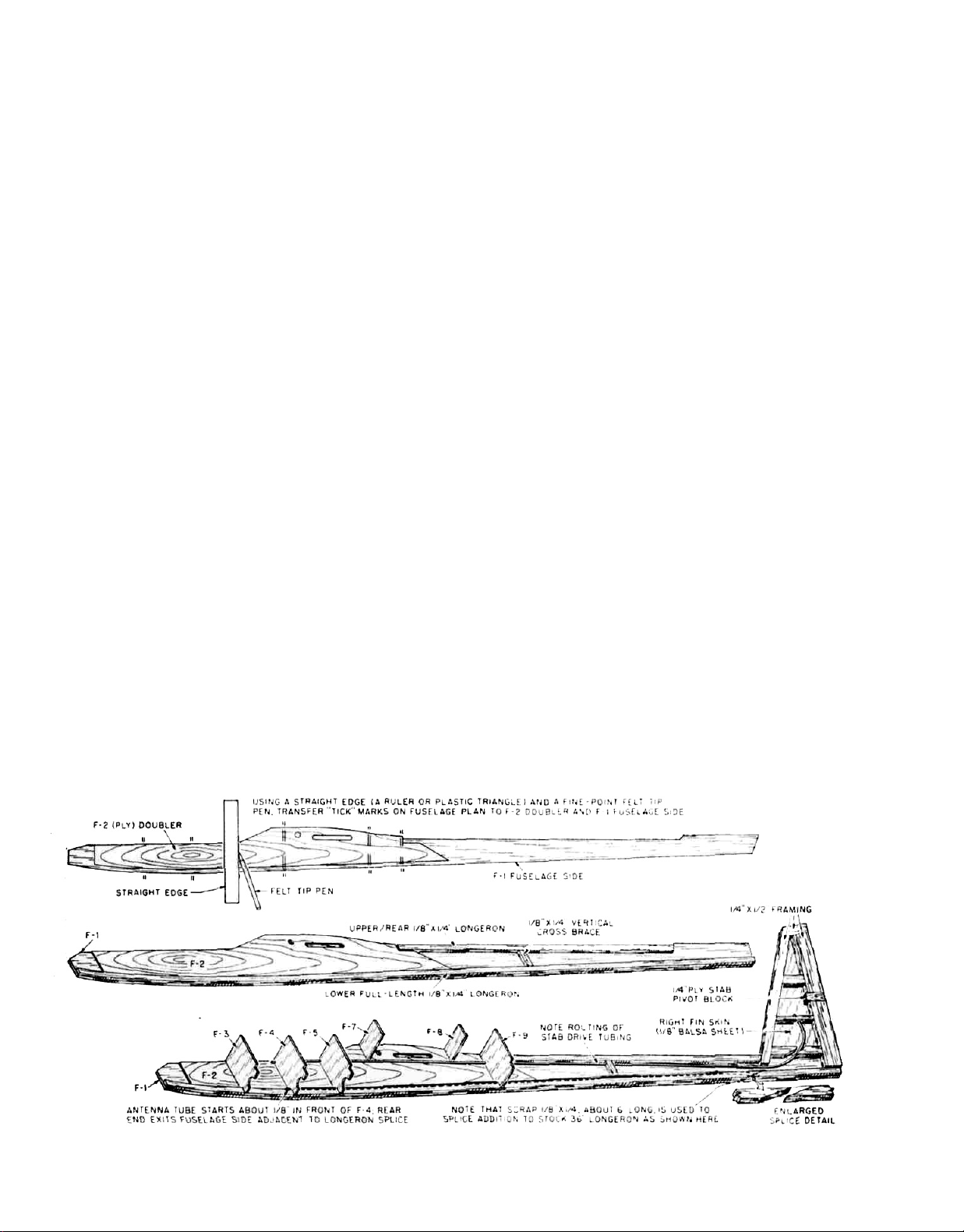
with the top edges of the fuselage sides—MAKE A
LEFT AND RIGHT FUSELAGE SIDE.
2. Using the
1/8" x 1/4" x 36"
balsa stock supplied, glue the
bottom fuselage longerons in place, starting at the
front of the F-2 doubler, pinning and gluing as you
work aft. Note that you will need to add an additional
6" of this longeron stock at the rear to complete to fulllength bottom longeron.
3. Cut and glue the top rear
1/8" x 1/4"
balsa longerons in
place. Note that this longeron extends from the back
of the F-9 former position to the leading edge of the
fin location where it is cut on an angle to match the
fin.
4. Using a sharp pencil and a straightedge, mark the
locations of all fuselage formers; F-3, F-4, F-5, F-7, F-8
and F-9, including the location of the rear
1/8"
x 1/4"
fuselage uprights, behind former F-9—mark these
locations on the right fuselage side. Holding the left
fuselage side to the right, so that they are accurately
matched, transfer the former locations to the left
fuselage side.
5. You will now need to drill an angled hole in the left
rear fuselage side for the outer plastic rudder cable
housing. Note its location on the plans and its distance from the rudder hinge line. Don't deviate from
this location because if it is too far forward, the rudder
cable may be prone to "bending" during'operation
and too far aft will mean that you can't get full rudder
throw. Repeat this process on the right fuselage side
for the internal antenna tube — first check the length
of your antenna to be sure that at least 1" of it will
protrude from the tube at the rear. A sharpened piece
of 1/8" dia. brass tubing works very well for drilling
these holes at the right angles and cleanly.
6. Pin, tape or lightly spot glue the two fuselage sides
together, with their outer surfaces touching — align
them to each other very carefully. Using a sanding
block, sand their outer edges to match them identically. While the sides are still together, carefully
match the main wing tube holes and access slots. We
have purposely made the main wing tube holes a
very tight fit, work carefully to open them up enough
to
accept a length of
11/32"
O.D.
brass
tubing
(3
pieces
supplied in the kit). The main wing tube holes must
line-up accurately.
7. Remove both W-1 ply wing root ribs and both F-10
fuselage root ribs carefully from their sheets.
Remove the main wing tube holes from each of the
ribs and access slots from the F-10 ribs—use a hobby
knife to assist you. Take one of the F-10 ribs and locate
the identification at the back. Drill a 1/8"dia. hole in this
rib,
at
90°
to
its
surface—this
rib
is
now
your
"drill
guide" for the rest of the ribs. Insert one of the main
wing wire tubes into the hole in the "drill guide" rib,
letting one end of it extend out from the rib about 1/16".
Now drill the 1/8" dia. hole needed in the remaining
F-10 and W-1's, by placing the rib onto the wing wire
tube, lining up the rib to be drilled with the "drill
guide" rib and drilling the hole—repeat this process
until all four ribs have accurately aligned and drilled
holes. Use the same procedure on the now matched
fuselage sides; insert one of the main wing wire
tubes into the hole in the fuselage side, slide an F-10
rib onto the tube and down flat against the outside of
the fuselage side, position as shown on the plans and
drill the 1/8" dia. hole. Repeat this process with the
other
fuselage side.
8. Remove ply tailskid from its sheet. Position the tailskid in place on one of the fuselage sides, as shown
on the plans. Mark its forward edge location on the
bottom, rear longeron in pencil. With a single edge
razor blade, remove approximately 1/32" of the thickness of the longeron, forward to the pencil mark —
this becomes half of the slot that the tailskid will fit
into. Repeat this process to the other fuselage side
to
create the 1/16" wide tailskid slot.
9. Lay the right fuselage side on your work
front
of
you with
the
inside
facing
you.
"Take
surface in
one of the
servos that you plan to use for either the stabilizator or
rudder and position it on the fuselage side between
the F-4 and F-5 former locations. Note the position of
the output arm. With a pencil, mark this location onto
the inner fuselage side. Note on the plans and crosssections that both the stab and rudder outer cable
housing tubes are positioned aft, through formers F-5
4
Page 5

and F-9 Now remove formers F-4, F-5 and F-9 from
their sheets Usingarulerand pencil,line the ruler up
with the mark made earlier for the servo output arm
location and draw a light intersect line at the positions of F-5 and F 9 Hold F 5 in place on the fuselage
side and mark the location of the intersect line onto
the former Repeat this for F 9 Mark the other side of
the formers for the output arm location for the rudder
cable housing Sand or file a 1/8" slot on each side of
these two formers, thus creating positioning and
mounting locations for the rudder and stab cable
housing tubes after these formers are in place (see
F-5 and F 9 cross sections) Lastly, sand or file a
similar slot in the lower right corner of formers F-4,
F-5 and F-9 for clearance of the internal antenna tube
Note on the plans, at least with the radio installation
shown, that the rudder and stab tubes are in place
just over the top of both the aileron and flap servo
rails Check how your installation will fit in place and
be sure everything clears
10. In this step we are going to "pre-position" both the
aileron and flap servos Studying the plans you can
see how the operation of these two servos affects the
two control surf aces and a I so what the relationshipof
their locations within the fuselage needs to be in
relationship to the wing panels Note that the flap
servo is located as far aft as possible to allow plenty
of clearance for the spring wing retainerand hooks In
the case of the use of a releasable or captive towhook
system, such as that shown, clearance is available for
getting to and tightening screws as needed Access
to the flap servo is directly through the top, rear
hatch, as shown The flap servo, as you can see,
needs to be positioned so that its output arm is
roughly centered within the slots on each side of the
fuselage This assures easy, bind-free operation of
the flaps and quick, non critical assembly of the airplane at the flying field Mark the locations of the
required two lengths of1/32"x 3/8" ply servo rails for the
flap servo onto the sides of the fuselage A trick that
we have used is to now cut a short length of 1/16" x 1/4"
balsa and glue it in place on each fuselage side to
later act as a gluing shelf and locator for the servo
rails We have used this technique for all of the servos
and it really saves time and frustration later on Next,
we are going to do the same thing for the aileron
servo Looking at the Top View of the fuselage plans,
you can see that access to this servo is meant to be
provided by the heavy fuselage canopy angle at this
section You will also note that we did not provide
aileron linkage holes through the fuselage sides or
the ply root ribs The reason for this is simple, different radio systems and servos would not all work For
this reason, these holes will have to be made by you,
based on your servos and their shapes The first step
for positioning the aileron servo is to develop the
proper output wheel for driving the ailerons Note the
drawing at the bottom of the fuselage plans This is a
typical servo output wheel that is trimmed as shown.
The two arm s that are I eft arc a bout 3/8"apart( hole-tohole). As you can see from the Top View shown on the
left-hand side of the wing plan, the left aileron clevis
attaches to one arm and the right side uses the other
arm. This sim ple system of connecting the ailerons to
the servo also imparts a highly desirable feature to
the actual operation of them—this is called differential Simply put, differential is the unequal movement
of the ailerons, in our case about 2 1 Full throw in
one direction will move one aileron a total of 1/2" "up"
and at the same time only moves the other aileron 1/4"
"down " Almost all flat-wing, high aspect ratio air-
craft (such as sailplanes) use some differential to
correct adverse yaw conditions The set-up we show
on the ANTARES plans works extremely well and has
the virtue of simplicity Once you have made this
output arm and have it in place on the aileron servo.
place the servo directly onto the right fuselage side,
about where it is shown on the plans Note that it
must fit in place behind F-5 and high enough to
position the output arm within the outline of F-10.
However, it must not be so high as to interfere with
the seating of the canopy Once satisfied, mark the
locations of the servo rails to mount it and mark or
roughly sketch a 1/4" dia circle where the output arm
will pick-up the aileron cable and clevis Again, we
would suggest that you memorialize the locations of
the aileron servo rails with the short lengths of 1/16" x
1/4" balsa for ease of installation later
Now drill a 1/4" dia. hole directly through the fuselage
side at the point marked for the aileron output arm.
This then becomes your "drill guide" for the remaining fuselage side and both W-1's and F-10's As before, use a length of 11/32" tube and 1/8" tube to first
accurately locate each part
to
the
"drill
guide"
fuse
side, then drill the 1/4" dia hole
11. Remove three (3) 36" lengths of the white cable housing tubes from your kit box Rough-up their outer
surf aces with medium sandpaper Do this completely,
we want adhesive to adhere to them Set these aside
for
installation shortly,
12.
Next, make
the
fin
tailpost
You can see
from
the
plans
that this is made from 1/4" x 1/2" balsa stock, laminated
edge-to-edge and cut to the taper shown Now locate
the shaped and drilled 1/4" ply stab pivot block Accu-
rately note its location on the tailpost with a pencil.
Take care here to be as accurate as possible—this
block ultimately locates your stabilator to the fin Cut
the tailpost apart to accept the pivot block and glue
the block in place Allow to dry and remove from the
building board.
13 Locate the die cut sheet holding the two 1/8" balsa "fin
skins " Remove these from the sheet and while holding them accurately together, matching outer edges
and the oblong cut outs, use a sanding block and
light sandpaper to "match" their outer edges identically—we want them exactly the same Now take one
of these skins and lay it directly over the plans and
with a pencil mark the locations of the top and center
1/4" x 1/2" balsa horizontal braces and the lower 1/4" sq.
cross-brace and stab cable tubing support. Set aside
for use in Step 14
14. You have already removed and modified formers F-4,
F-5 and F-9 back in Step 9 Remove formers F-7 and
F-8 from their sheet as well Formers F 5, F-7, F-8 and
F-9 are all exactly the same width, 15/8 Hold them all
together and use a sanding block to make sure
they're all the same width Lay the right fuselage side
over the side view of the plans and pin accurately in
5
Page 6

place Using a triangle, glue formers F 5, F-7, F 8 and
F-9 in place at 90 to the fuselage side, using the
pencil marks made earlier for location (please note
the "alternate F-7 location" note and the reason for it
on the plans) Moving to the rear of the fuselage side,
glue the previously marked (Step 13) fin skin to the
top, rear section Now glue the previously assembled
tailpost and stab pivot block assembly to the rear of
the fuselage side and fin skin Cut, fit and glue the 1/4"
x 1/2" balsa fin leading edge in place to the fuselage
side and fin skin (note that this piece terminates at the
bottom edge of the top, rear fuselage 1/8" x 1/4" longe-
ron) Cut, fit and glue the two top 1/4" x 1/2" balsa
horizontal braces whose locations were noted earlier
on the fin skin Cut, fit but do not glue the 1/4" sq.
brace Using the plans, note the location of the stab
cable housing tube and drill an 1/8 dia hole through
this brace at the point marked—now glue this brace
in place Cut, fit but do not glue the bottom 1/4" x 1/2"
balsa fuselage fin brace Again using the plans, note
the location of the stab tubing and the bend it takes at
this point Use an X acto knife or a Dremel tool with a
small router bit to carve a channel", at least 1/8" deep
into this brace to countersink and house the tubing,
once
satisfied, glue this
last
remaining brace in place,
half of its width on the fin skin and the other half on
the fuselage side Inspect your work carefully for
good glue joints, double glue if necessary Onceallof
this is sealed-up, you will not have access to it again
15.
Take one of the 36", roughed-up cable housing tubes
and install it (without glue yet) in place, through the
slots in formers F-5 and F 9, the channel cut in the
bottom fin fuselage brace and through the hole in the
1/4" sq brace on the fin skin Note that this stab drive
tube is meant to fit from just inside of the rudder stab
servo compartment, F 5, along the fuselage side,
through the slot in F-9, all the way along the bottom
edge of the top, rear longeron, through the channel
cut earlier in the bottom fin fuselage brace and finally
through the hole drilled in the 1/4"sq brace We used a
thick CA adhesive, such as Pacer's Zap-a-Gap or SloZap to now glue this tube in place along its entire
length Be sure that it is firmly glued in place—we
don't want it moving Using the marks made earlier,
glue the short 1/8" x 1/4" balsa upright in place between
the stab tube and the bottom fuse longeron
16.
Remove the right fuselage side assembly from the
building board. The left fuselage side is now pre-
pared for assembly to the right byfirstgluing in place
the two short lengths of 1/8" x 1/4" balsa that is the rear
upright — note the 1/8" wide channel that is left to
capture the rudder cable drive tube as it curves down
toward the rear, angled rudder tube exist hole, drilled
earlier. Trial-fit the left fuselage side to the right side
assembly Since all of the formers in place are the
same width, the left fuselage side should come in
firm,
square contact
with
their left edges Once
fied, carefully glue the left fuselage side in place
against F-5, F-7, F-8 and F 9, using the location marks
made earlier Take pains to be sure that the structure
is
truely square
17.
Install another 36" length of cable housing tubing
along the left fuselage side, from just forward of F-5,
through its slot, F-9, along the fuse side. through the
satis-
channel in the upright and out the angled exit hole at
the rear Leave some tubing exposed at the rear for
trimming (see plans) As with the stab tube, glue the
rudder tube in place completely along its entire
length.
18.
Cut, fit and glue the
1/8"x1/4"balsa
cross-brace
in
place
on the fuselage bottom, just behind the towhook
location, as shown Use CA adhesive to glue former
F-4 in place while gently and equally bending the two
fuselage sides together at the nose, when dry repeat
the process while installing former F 3 Now glue the
shaped hardwood noseblock in place Note that this
block fits between the two fuselage sides, flush with
the bottom edges of each and up against the edges of
the two F-2 ply fuselage doublers Tape and/or clamp
in position and allow to dry Cut, fit and glue the two
lengths of 1/4" triangular stock in place behind the
noseblock As you proceed through this step we
strongly suggest that you continually check for symmetry and squareness of the assembly
19. Locate and glue the shaped balsa forward canopy
mount in place against the top rear of the noseblock
and the fuselage sides Sand the edges flush with the
fuselage sides Carefully remove ply former F-6 from
its sheet Clean up the inside edges with sandpaper.
With a sanding block, bevel the two bottom edges of
this former to match the fuselage sides when it's in
place Note that when in place this former stands tall
of the fuselage sides, this is to pick up the top 1/8"
sheet Glue F 6 in place and when dry, sand its outer
edges flush with the fuselage sides
20 Using about an 8" length of one of the 1/16" x 3" x 36"
balsa sheets provided, cut and fit the canopy/hatch
base Use your sanding block to bevel each end of
this base to fit accurately to the forward canopy hatch
block and the angled F 6 rear former Lightly tack glue
this piece in place and sand its edges flush with the
fuselage sides Remove canopy formers C-2, C-3, C-4
and C-5 from their sheet Sand the required bevel into
the bottoms of C-2 and C-5 Carefully glue these two
formers in place on the canopy base being careful to
not glue them to the fuselage — their outside edges
should be flush with the fuselage sides Now center
and glue the C 3 and C 4 formers in place per the
plans (these fit directly over F-3 and F 4 respectively).
Remove the two C-1 canopy sides from their sheets.
Using a flat work surface, glue and pin the y4"tnangular stock piovided to the inside top edge of the C-1
canopy sides — be sure to make a right
and a left
When dry, carefully fit these sides in place, trim as
needed to get a good fit and glue them in place With
the canopy assembly still tack glued to the fuselage,
use your sanding block to bring the sides flush with
the fuselage sides
21. With ready access to both the inside of the canopy/
hatch and the fuselage, now is the time to build the
canopy hold-down system Note the views shown in
the upper left corner of the fuselage plans These
demonstrate how the canopy is secured to the fusel-
age, at the nose with a ply 'lip' that is glued to the
bottom of the canopy base and fits beneath the
canopy hatch block, in the middle it is held to the
fuselage by two wire hooks and a rubber band and at
6
Page 7

the
rear
there
is a length
(1/8" x 1/4" x 1-5/8")
balsa
to the back of C-5 that fits into the cut out in F-6 This
system is easy to install at this stage and has worked
beautifully in actual practice Cut, fit and glue the ply
"lip in place, being careful not to glue it to the fuselage Cut or drill the 3/8"dia hole inthecanopy base—
in the center — just behind C 4 Bend and install the
two wire hooks shown, one on C-4 and the other
toward the bottom of F-4 Cut, fit and glue the 1/8" 1/4"
x
1-5/8""
balsa
piece
to the
back
of
C-5
(trim this piece
carefully for a qood, snug fit as it is meant to keep the
canopy from shifting left or right Once satisfied, use
the piece of 1/8" x 3" x 12" balsa provided to sheet
(cross-grain) the top of the canopy (see side view).
When dry, sand the edges flush with the sides.
22.
From your packaged wood parts and hardware,
locate the 11/32" 0 D x 2-5/16"
main
wing
wire tube, the
1/8" O.D. x 2-3/16" rear incidence pin tube and the maple
U-block tube nest Use rough sandpaper to rough-up
the outside surfaces of the brass tubes Insert the
tubes into their respective holes and center them —
note that each tube protrudes past the fuselage sides
to pick-up the installation of F-10 later Now trial-fit
the U-block onto the main wing tube inside of the
fuselage, sand edges as needed for good fit and
remove for gluing Cut a 1-5/8" length of 1/8" x 1/4" balsa
to fit beneath the rear incidence tube and against F 8.
Using 1-hour epoxy, apply glue to each end of the Ublock and fill the channel a bout one third Slide the U-block
over the tube as shown on the plans—carefully
wipe-off the glue that oozes onto the fuselage sides
Using more epoxy, "bury' the tube in glue, rotate the
tube itself to make sure there are no air bubbles.
Again using epoxy, glue the 1/8" x 1/4" balsa shelf
directly under the rear incidence tube and to F-8
"Bury" this tube in adhesive as well Take a break and
let the whole thing set-up — watch for runs
23.
Use the remaining piece of roughed-up outer plastic
tube to make the internal antenna housing Install this
tube from just inside of the receiver compartment (in
front of F-4), aft along the bottom right fuselage side
and out through the angled hole made earlier. Note
that the tube fits into the slots you made in F-4, F-5
and F-9 Glue securely in place.
24
. Decision time, are you going to use a radio-actuated
captive towhook system, such as the Fourmost Products shown on the plans or the fixed towhook pro-
vided in the kit While both systems work well, if you
are planning contest work with your ANTARES, we
highly recommend a captive system such as that
shown You will note on the plans that we are releasing the towhook by radio, using a 3/4" "up" elevator
signal. While at first this might sound suicidal, in
actual practice this system, in conjunction with use of
flaps on launch, makes for wonderfully tall "ping"
launches You might take a look at the Flying section
of this manual and read how we have been doing this
before you decide which towhook system to use
Installation of the Fourmost hook is quite simple and
accurately depicted on the plans In fact, when we
used this system, WP pro-slotted the ply floor,
installed the mounting rails and secured the Fourmost hook in place on them and then installed the ply
floor to the fuselage
glued
If you are installing the stock, fixed towhook, start by
locating
the 3/32" x 2" x 17"
ply
forward
fuselage
Mark a centerline down its length in pencil. Hold it in
position against the bottom of fuselage with its rear
edge covering half of the 1/8" x 1/4" cross-brace be-
tween F-5 and F-9 With a pencil, mark the outside
fuselage side outlines, trim off the excess off with a
saw Glue the ply floor in place on the bottom of the
fuselage with the previously drawn centerline on the
outside
Use a 5-7/167"
length of the
3/32" x 3/8"
ply stock
provided and glue it in place to the inside centerofthe
ply floor, between F-5 and the rear cross-brace as
shown on the plans From the plans, determine the
towhook location and from the outside, drill a 1/8" dia.
hole through the fuselage floor and the ply doubler
just installed. Epoxy the 4-40 blind nut provided into
this hole from the inside — use glue liberally around
the nut's base without getting any into the threads.
25. Using the remaining 1/8" balsa sheet, finish sheeting
the top of the fuselage as shown on the plans Note
that one piece extends aft from the rear face of F-6 to
the rear edge of F-7 This sheeting is then resumed
(always cross-grain) from the forward edge of F-8
back to the rear edge of F-9 "Cap" the top of the two
fuselage sides between the two edges of the sheeting
with 1/8" x 1/4" balsa, aligning the outer edges with the
fuselage sides The resulting rectangular opening in
the fuselage top is for the access hatch.
26 As shown on the plans, the access hatch is a simple
frame made from 1/8" x 1/4" balsa, on edge, with 1/8" x
1/4" gussets in each of the four corners We used
scraps of bond paper front, back and on each side for
spacing while making this frame. As shown, install
two pieces of 1/8" x 1/4" balsa as shelves on the back
face of F-7 and the front face of F-8 to seat this hatch.
Sheet the hatch with the last of the 1/8" balsa provided,
cross-grain Lightly sand the edges flush with the
frame and lightly tack glue the hatch in place for final
sanding
27. Trim off and sand flush any protruding rudder and
antenna tubes on the right and left fuselage sides.
Trial-fit the two rear fuselage sides together to be sure
they will fit without any obstructions Once satisfied,
we will now glue the two fuselage sides together at
the rear This step is important and should be done
carefully to avoid unequal bending of the fuselage
sides (boloid) We would suggest that you place the
fuselage directly over the top view on the plans as
this supplies you with a centerline reference. Firmly
secure the fuselage with heavy objects that have right
angles (bricks, one on each side, are great). Use a
slow drying glue such as 1-hour epoxy and apply
adhesive to the inside of the fuselage sides, just
ahead of the fin (see plans), aft to the tail —keep glue
out of the tailskid slot Clamp the structure together.
Check very carefully for squareness and alignment.
Make sure that the fin structure is at 90° to the work
surface and that it is aligned down the center of the
fuselage when viewed from the front Let this assem-
bly cure completely.
28. From your hardware, locate one length of 36" braided
metal cable and the stab drive fitting The stab drive
hole in this small fitting is slightly undersize and
needs
to
have a #42 or
7
3/32"dia.
drill
bit
run
through
floor.
it.
Page 8

You don't want the fit between the forward stab drive
wire and the fitting loose but it still should be made to
pass through the fitting without binding Insert one
end of the cable into the "tube" end of the fitting and
solder securely (we recommend the use of Hams'
STAY-BRITE silver solder and particularly their STAYCLEAN flux for this and all other solder joints on this
airplane) Clean the joint completely and insert the
other end of the cable through the stab tube at the fin
and push it through to the servo compartment Cutoff the excess, leaving yourself a little extra to trim
later when installing thecoupler Once satisfied, usea
1/8" dia drill bit through the rear 1/4" ply stab pivot
block hole and right fin skin Glue the left fin skin in
place, align carefully and allow to dry
29. Cut, fit and glue the 1/8" x 1/4" fuselage cross braces in
place, top and bottom, at the aft mid point of the
fuselage Cut, fit and glue the 1/4" balsa turtle-deck in
place on the top rear of the fuselage — note the bevel
needed for the fin's leading edge angle Turn the fuselage over and using the 3/32" x 3'x 18" balsa provided,
sheet the bottom from the rear edge of the ply floor
all the way back to the tailpost, keeping glue out of the
tailskid slot Note that this sheeting is applied crossgrain Use a sharp razor blade to cut the tailskid slot
into the bottom sheet at the tail Glue the tailskid in
place Locate the shaped 1/2" fuselage/fin fairing If
needed, use your sanding block to achieve a precise
fit and glue this fairing in place Use a sanding block
and 120 grit sandpaper to sand the fuselage sides, top
and bottom smooth Pay particular attention to the
side-view contour at the top of the fuselage where the
1/8" sheet meets the 1/4" turtledeck Sand the side and
top view shapes into the fuselage all the way through
the noseblock but don't start rounding any edges yet.
Work around the protruding wing tubes for now Note
the fin/fuselage joints are completely flush and
smooth Use the 1/8" dia drill to clear-out the remain-
ing hole needed in the left fin skin Trim the 1/8"O D x
7/8" brass tube used for the rear stab pivot bushing to a
little more than 1/2" long Rough-up its surface and
glue it in place into the hole provided atthe rear of the
fin, sand the edges flush with the fin.
CUT I/I6"SLOT IN FUSELAGE BOTTOM TO ACCEPT
TAILSKID. CHECK FIT, THEN GLUE IN PLACE.
30. Temporarily install thetwo F 10's onto theirtubes and
against the fuselage sides Use a soft pencil to trace
their outline's onto the fuselage sides and remove the
ribs Using the plans for reference start sanding the
fuselage to final shape Note that at the top of the
fuselage, at the F 10 location, it is only rounded to the
outline you just drew, don't undercut it — see cross
sections Use the heavier grits of sandpaper for the
initial shapes, progressing to lighter grades to finishup This fuselage and fin can be sanded to an almost
ovoid shape in many of the cross sections — take
yourtimeanddoa complete and tho rough job, it can
look really sexy when you do it right Note the suggestion of adding a couple of pieces of scrap 1/8" balsa
to each side of the tailskid and then sanding the
whole thing into tho cross section of the fuselage.
When finished, carefully break loose the canopy.
RUDDER
1. Construct the rudder over the plans, starting with the
outside 1/4"x 1/2" balsa frame, the three corner gussets
and then the 3/32" x 1/4" geodetic "ribs" and their two
gussets Use a sanding block lightly on each side of
this structure
2 Locate and remove the two R-1 (ply) rudder horn
mounts Sandtheir edges flat andgluein place atthe
bottom leading edge of the rudder—one on each
side
3 Use the 1/16" x 1/2" x 36 balsa strip provided to "build-
up" each side of the rudder, as shown on the
exploded view on the plans.
4 Use a sanding block to bevel the leading
rudder, on its centerline, to provide
movement—
see cross section on plans.
edge of the
unobstructed
5 Sand rudder to its final cross section shape with a
sanding block Cut slots for hinges in the leading
edge of the rudder and the trailing edge of the fin—
check fit Mount rudder in place on the fin and
hold
with masking tape at the hinge line Sand the final fin/
rudder shapes rounding all edges carefully to match
— see plans Remove rudder and lunges from fin.
STABILATOR
1. Locate and remove the two required E-1's and E-2
stab parts from their die-cut sheet Start construction
by using the remaining piece ofthe1/16"x3"x 36" balsa
sheet that was used for making the canopy base, to
make four (4) 1/16" duplicates, without slots, of both
E 1 and E-2 A sharp razor and straight edge will do
the job quickly—note the desired grain direction.
(Note that if you wish to build a thicker stabilator, as
discussed in the F3B Modification section, substitute
the 1/16" stock with 1/8" sheet balsa Realize that this
means a change in the size of the leading edge, spar
and qeodetic material—the tips and trailing edge
material could be shimmed with scrap to center
them )
2 Using the 3/32" x 3/8" ply stock provided, cut two 3-1/16"
lengths to serve as the stabilator "roots" (save the
balance of the ply stock, it will be used for servo
mounting rails) As the drawing shows, accurately
mark and drill the 1/8" dia holes for the brass tubes
We think this is best done with a drill press of some
8
Page 9

kind, since the right angles are important. At this
point, if you are going ahead with the VA" stabs, you
should trim Vis" off of each side of these ribs. We
would suggest that now is a good time to check and
make sure that these holes are properly spaced and
will
fit.
Locate
the two W dia. x 2%" M.W. stab joining wires. Temporarily install the four tubes into the holes in the ply
stab root ribs and assemble these to the fin with the
joining wires. The fit should be smooth and non-
binding when moved up and down at the front of the
fin. All of this serves to confirm that the hole spacing
is correct—if it isn't, correct as needed.
3. Next, take one of the 1/8" O.D. stab tubes and slip the
1/8" I.D. wheel collar over one end. As shown on the
plans, mark the location of the wheel collar's setscrew hole, removethecollarand fileorgrind a notch
into and through the wall of the tube large enough to
let the set-screw pass, when tightened. Carefully
clean-out any metal "flash" on the inside and outside
of the tube, re-install the collar and test fit the setscrew for clearance. Once satisfied, apply a small
amount of thick CA adhesive to the collar tube joint.
This is your one and only stab-locking tube (see stab
plan).
4. Cut or route-out a slot in one of the rear E-2's to
the
wheel collar—trial-fit to be sure. Leaving the tube
and collar in place in the
the
1/16" balsa laminates in place with your fingers,
press
indention on the inside of each skin. "Scoop-out"
firmly with your fingers to create the collar's
four
(4)
Va"
O.D. x TVie"
E-2 p
brass
art, fit and hold two
tubes and
accept
balsa carefully from the indented areas, thus leaving
clearance for the collar. In the bottom skin, carefully
make a 1/8" hole for the set-screw.
5. Assemble the stabs directly over the plans
with accurately locating and pinning in place the 1/8"X
1/4" upright "spar". Assemble the rest of the
structure as shown being careful to not get glue into
the joiner tubes. Be sure to use epoxy to secure the
tubes into their respective slots and that these tubes
are laying flat.
6. When dry, remove the stabs from the plan and use
your sanding block to sand them flat. Next, hold them
together and "match" their outside shapes—you
want them identical. Before going any further, trial-fit
the stabs to the fin. You will have to trim a little of the
length of the joiner wires to get the stabs to fit flush
with the fin sides as we have left these a little longer
for fitting purposes. What you're looking for during
this trial-fit is that the two stabs sit at 90° to the fin
sides and that their roots are flush with the fin sides
as well. Remove the stab halves and the joiner wires.
File or grind a small "flat" on one end of the rear
joiner wire for the set screw to bottom-out on when in
place—re-install and test-fit, including the set-screw.
Once satisfied, remove all of the components from
the fuselage.
7. As with the rudder, use your sanding block and
of
grit sandpaper to carefully bring the stabs down
the cross sections shown. Note that what you are
trying to achieve here is a symmetrical airfoil. Also
starting
stab
120
to
9
Page 10

note that the "entry" or lead ing edges a re not particu-
larly sharp, but not just "rounded" either. Approach
thistaskwith care tocreatethe intended shapes. Final
sand with light paper and set aside for covering.
BALLASTING
As
we mentioned earlier in the Introduction to this
manual, having the capability to incrementally increase
your wing loading to match certain weather or contest
conditions is of great value and simply adds additional
scope to your flying abilities with the ANTARES If you
have opted to build-in the four ballast tubes into the
wings, you now need to develop the weights necessary to
fill
them
As
mentioned
earlier,
we
chose
to
use 2'lengths
of1/2"O.D. brass tubing ("off the shelf" K&S brand), filled
with poured lead These should weigh about 2.5 ounces
each. Each end of these "slugs" should be carefully
dressed so that they slip easily into and out of the wing's
ballast tubes. Since each wing tube has a capacity of
13-3/4",
then
each
tube
can
hold
up
to a total of six
(6)
slugs
and therefore the total system can hold up to 24 slugs or
60 additional ounces of ballast.
IMPORTANT:
When melting and pouring lead use extreme caution.
Always work with this material in a well ventilated area,
preferably outdoors Always wear heat resistant gloves
Always wear a protective mask over your mouth and
nostrils to avoid fumes (such as a painter's mask). Avoid
prolonged contact with the lead itself to your skin. Always
wear safety glasses or goggles'"
To make these slugs you will need to obtain four (4) stock
12" lengths of K&S Engineering's 1/2" O D. tubing, their
stock #139 and about 4 pounds of lead—we use large
sinkers obtained from the local tackle shop, while the
tubing itself is available from your local hobby shop The
lead was melted in an old iron pot over a hot plate The
tubing was prepared for filling by first using thick CA
adhesive to glue a small circle of 1/8" plywood over one
end The tube was then securely propped-up, on the
ground, sealed end down, with bricks The melted lead
(about 1 pound at a time) was then poured into the open
end of the tube until filled and allowed to cool on it's own
—do not attempt to cool it with water or any other type of
coolant as this will cause shrinkage of the lead within the
tube. Once the tube has cooled and can be handled,
knock-off the 1/8" ply plug Repeat this process on the
remaining three tubes until you have four lead filled 12"
long slugs.
The slugs are now marked off in 2" increments and sawed
into individual slugs We used a hacksaw for this pur-
pose Now dress the ends of each of the slugs to remove
flash. When complete, you should have 24, 2" brasslined lead ballasting slugs Minor discrepancies in
weight between these slugs is not important while anything over about 1/3rd of an ounce might be—check them
with a scale.
Obviously, the lead slugs are loaded into the wing tubes
from the wing roots but these slugs must be held in place,
as close to the fuselage as possible without having the
freedom to move outboard We use pre-measured and
cut lengths of common 1/2" dowel (found in most hardware and I umber supply stores) to hold the slugs in place
These are sanded carefully to fit freely into the wing
tubes So, in order to load, say, four lead slugs into the
wings you will need four 11 3/4" long 1/2" dia dowel "fil-
lers" These fillers a re inserted into the wing ballast tubes
first, followed by four slugs This should render the slugs
im mobile a gainst the fuselage F-10 ply ribs and the dowel
fillers in the wing tubes In this particular instance, you
have now increased the weight of the airplane by 10
ounces (plus the weight of the dowels, about .064 ounces
per inch) and the wing loading accordingly.
If you are so inclined, as we were, you can now make up a
carrying case of sorts that will hold all of your ballast
slugs and dowel fillers We have gone as far as including
in this case a chart that shows all of the possible wing
loading configurations obtainable with ballast—this case
goes with us to all flying sessions and contests and has
proven itself to be a valuable tool in handling both condi-
tions (weather) and tasks
Remember, all ballast must be as close to the fuselage as
possible, never load the slugs first Also remember that
all ballasting must be symmetrical, the same amount in
the same location on each side of the fuselage Lastly,
remember that the dowel fillers are mandatory for this
ballasting system—a loose lead slug that weighs 2-1/2
ounces develops inertia quickly and can rearrange the
inside of your wing—be sure that it is immobilized by the
filler dowels
WING ASSEMBLY
Before starting this assembly sequence you must decide
whether to build-in the ballast tube option The option is
relatively easy, requiring only the four Estes #BT-5 rocket
tube bodies and the holes for them in the effected wing
ribs. Just make sure that when you make the required
holes and insert the tubes, that they don't bend in any
way—they must be straight
1. Start by removing all of the wing ri bs, not the trai lingedge "riblets", from their die-cut sheets Do this
carefully, use the X-acto knife if needed. We have
made it a practice of stacking all of the ribs together,
in the order that they are used and lightly sanding
them to uniform shape with the sanding block Also
be sure that the top and bottom spar notches line-up,
again using the X-acto knife if needed.
2 Next we are going to prepare all of the 1/16" wing
sheeting for use Note that the top and bottom lead-
ing-edge sheeting is 1/16" x 4" x 48", in other words, all
one piece The rest of the sheeting must be "scarfed"
together from the 36" and 18" lengths to produce the
required 48" sheets While the diagram shows you
how to do this, the Wing plan shows you exactly
where to cut and join these sheets (We prefer using
white glue or aliphatic resin type glues, such as
Titebond for these Joints ) This operation should be
done carefully to produce good joints and straight
edges When dry, lightly use a sanding block to
smooth the joints until they cannot be felt with your
fingers When complete, you should have the following pieces of wing sheeting available for assembly:
4 pcs. 1/16" x 4" x 48" unscarfed, top and bottom
leading-edge
4 pcs. 1/16" x 4" x 48" scarfed from 36" and 18" lengths,
top and bottom T.E
10
Page 11

2 pcs 1/16" x3" x 48" scarfed from 36" and 18" lengths,
top center section
2 pcs.
1/16"x3"x 18"
It is important to note that all of the wing sheeting
pieces have clean, straight edges Use a metal
straight edge and a razor to do this Lastly use the
straight edge to accurately cut the taper into the four
trailing edge sheets, 3-1/8 at the root to 3-1/2 at W 20
3. Lay the bottom trailing edge sheeting in place on the
plans and with a pencil mark the aileron flap hinge
line at each end of it—1 1/2" ahead of the trailing edge
Use a straight edge to connect these two marks with a
soft pencil Now note the location, at W 12 of the
aileron/flap break line Again using a straight edge,
cut this line through the sheeting from the hinge line
back to the trailing edge Now accurately pin the
trailing edge sheeting directly over the wing plan
(your plans should be covered with clear plastic
material such as the backing from a rollofMonokote)
4 Now accurately position and pin in place the bottom
leading edge sheeting on the plan—note that this
sheet extends from the rear edge of the bottom spar,
forward to the front edge of the 3/8 sq leading edge
Cut, fit and glue the bottom center section sheeting in
place Using the rib tick marks provided on the
plan, mark the location of all ribs—W 2 through W 20
on the bottom wing sheeting Cut, fit and glue all
bottom 1/16" x 1/4" cap strips in place from W 7 out to
W 20 Accurately locate and glue in place the bottom
1/8" x 3/8" x 48 spruce spar Use a straight edge to make
certain that it is truly straight and use pins and blocks
to hold it that way.
unscarfed, bottom center section
5 Once again using your straight edge for alignment,
gluethe1/4 sg x48"wing trailing edge in place along
the hinge line drawn earlier The 1/4" sq leading edges
for the ailerons and flaps (two pieces, one for each
surface, cut from the 48 stock provided) are now
glued in place to the bottom sheeting, also along the
hinge line—do not glue these to the wing's trailing
edge—spacing these two pieces from the trailing
edge of the wing with scraps of common card stock.
6 Using the top spars (1/8" x3/8" x 48"), lift and support the
bottom leading edge sheeting to conform to the
bottom, forward shape of the ribs Take care to accu-
rately position this spacer" to provide uniform
sheeting curvature from the root to the tip Check this
curvature with the ribs you are looking for uniform
contact with them from the spar forward
7. Locate and remove both W 21 's and W-22's (ply) from
their sheets Note that these parts are tapered and
that the wing root angle is in their root ends, therefore
there is a definite way they are to be installed Use
your sanding block to clean up their edges Glue the
forward W 21 in place to the bottom sheeting and the
leading edge of the spar, with its angled inboard end
terminating at the inboard edge of the wing sheeting
—be sure that W 21 is in place at 90° to the bottom
sheeting to assure proper rib-end contact
8 Locate ply root rib W 1 and the 1/8" W-2A "half-rib".
Hold W 1 in place against the inboard end of the
wing, W 21 and the 1/4" sq trailing edge Hold W-2A in
place against W 1,with its rear edge up against W-21.
Use a pencil to outline the forward 1/4"dia hole drilled
in W 1 for the aileron linkage onto W-2A, set aside
W-1 for now Drill a 1/8 dia hole through the approxi-
11
Page 12

NOTE HOW UPPER SPAR IS USED AS A WEDGE
TO SUPPORT BOTTOM FRONT SHEETING
WITH WING FRAMEWORK PINNED TO A FLAT
WORK AREA, PRESS SPAR BACK UNTIL THE
SHEETING MATCHES RIB CONTOUR
mate center of the 1/4"dia pencil mark you just made
on W-2A Using this rib as your guide, drill similar 1/8"
dia holes through all of the remaining ribs that hold
the aileron cable tube—W 3A through W 15
9. Starting with tip rib W 20 and working inboard, glue
all wing ribs in place * Use a triangle or a small block
with right angles to ensure that these ribs are in place
at 90° to the bottom sheeting *NOTE W-2A is
installed at the same angle as the inboard end of
W-21, this provides the root dihedral angle required.
Do not install W-2B or W-3B at this time.
10. Locate and glue the 3/8" sq leading edge in place
11 Cut, glue and fit the 1/16" x 1/4" "sheeting shelves" that
fit between each rib, flush with their top edges and
against the inside of the 3/8 sq leading edge These
are made from the 1/16" x 1/4" x 36 stock provided
12. Locate,
flap "riblets" on the bottom sheeting, againstthe rear
edge of the 1/4"sq stock in place Note that there are
two #12's provided for each wing panel and that they
are glued in place on each side of the aileron flap cut
made earlier, use a piece of card stock to space them
13. Remove the top spars from underneath the leading
edges of the wing panels and temporarily install
them into the top rib slots Align their inboard ends
flush with the top inboard end of W-21 Using the
remove and glue in place all of the aileron and
spars as spacers, glue the rear ply W 22's in place to
the bottom sheeting and the rear face of the bottom
spar—do not glue to the top spdr Note that W 22 is
meant to fit from the inboard edge of the bottom
wing sheeting out to rib W 4B Remove the top spar
and re-install it beneath the leading edge of the wing
panel
14 Locate the bag containing the 3/8" x 5/8" x 3" vertical-
grain balsa shear webs These are now trimmed and
accurately installed between each rib starting from
W 4B out to W 20 Note that these webs must be
carefully fitted in place between each rib and the top
and bottom spar locations—do not allow any gaps or
bad joints, the integrity of your wing depends on
these webs!
15 Use the 1/16" x 1" x 36 balsa strips provided to cut, fit
and glue in place the horizontal grain web facing
caps which are full depth, from W 9 through W 20
These are glued to the front faces of all the 3/8" vertical
webs just installed—see plans and cross sections
16 In this step we want to prepare the top of the wing for
sheeting This is best done with the largest, longest
Sanding bloc k that you have with light sandpaper
The tops of the 1/4" sq trailing edges and the 1/4" sq.
aileron and flap leading edges have to be tapered as
shown on the plans Also, the bottom, trailing edge
sheeting must be tapered as shown Take your time
here to ensure accuracy We have used masking tape
over the ribs, in front of and behind the 1/4" sq.
material to avoid gouging Once satisfied, cut, fit and
glue the 3/32" ply aileron and flap horn mounts into the
locations shown (riblet 8 and 16) These too are
tapered—see cross sections
17 Locate and mark the required hole positions for the
aileron and flap horns (4 40 flat head bolts) The
measurement from the hinge line back to the centerline of these holes is 5/16" Drill these holes, at right
angles to the work surface with either a 5/64" dia drill
bit or a #42 index bit
12
Page 13

18.
Glue rib W 3B in place Glue rib W 2B in place at the
correct root angle Remove the wing panels from
your
building board.
19 In this step you are going to "final sand" the correct
wing root angle into each panel The cor rect angle, as
shown ontheplans is imparted to the root ribs when
the tip, at W 20, is blocked up to 2" off of your work
surface Take pains to firmly position each panel on
the edge of your work surface before sanding this
angle into the root ribs—note th at the leading edge of
the wing, when viewed from the top is 90 to the root.
Once satisfied with the positioning of the wing panel,
use a large, flat sanding block with heavy sandpaper
to sand the root angle into each wing root
20.
Glue ply wing root ribs W 1 in place to wing roots,
accurately lining-up the main wing tube holes with
the cavity between W 21 and W-22 The trailing edge
ofthisshortened nbendsattheflaphingeline Runa
1/8" dia drill bit through the rear incidence pin tube
hold in W 1 and through W 2B Locate and epoxy the
1/2" sq maple wing hook mounting blocks in place
against the inside of W 2B—note this block is positioned 9/16" behind W-22
21.
Locate and get ready, the main
5/16" I D x 2-5/8"
brass
main wing tubes, the 5/16 dia main wing rod, the rear
3/32" I D x 1-3/16"
incidence tubes, the
3/32"
dia x 4-5/8"
MW incidence pin, W 23 s (ply, four) Also, in the
small bag of wood parts locate the four pieces of 1/16"
x
3/8" x 2-1/2"
ply
(these
are
spar box
"fillers",
see cross
sections at the wing root)
First rough-up the outside surface of all four of the
brass tubes with 120 grit sandpaper Next you need to
cap-off one end of each of these tubes to present
epoxy from seeping inside when they're mounted.
The easiest way to do this is to hold one end of the
tube over a piece of bond paper and apply CA adhesive to the joint When set use a small sanding block
to sand away excess, leaving just the capped end of
the tubing Next, trim, fit and glue the bottom 1/16" x
3/8" x 2-1/2"
spar box "filler' in
place
on top of the
bottom spar, between W-1 and W-4B Trim and sand
the four W-23's to fit in place but do not glue yet
We are now going to install the wing tubes, followed
by using the two wing rods to fixture" their final
locations Start by mixing a batch of slow drying
epoxy (use Hobby Poxy Formula 2) Apply glue liberally to theinsidoofthes par box where the main wing
tubesfit—fill itto the bottom of the hole inW 1 Insert
the main wing tubes, capped end first, through W-1.
Try to make sure there are no air bubbles Insert, but
do not glue yet the rear incidence pin wing tubes in
place, capped end first through 3/32" 1 Place the two
wing panels on your work surface with the twoW-1's
facing each other Prop one panel up at the tip 2", slide
the two wing rods inplaceinthcir tubes in this panel
Slip the other panel onto the wing rods and prop its
tip up to 2 also Make sure the two W 1 root ribs are
firmly in place on the work surface (use weights, if
needed) and that they are parallel (Note, it is not
necessary to push the two panels together tightly,
just enough to "bottom out" the two rods is suffi-
cient ) Apply epoxy liberally on and about the rear
incidence tubes, fittheW 23 sin place—hit them with
a little CA to keep them from moving—and fill the
cavity between them to the top with epoxy Note that
we have not yet filled the main wing tube cavity, this
will be done in due time Allow this entire assembly to
cure overnight.
22 Remove the wing rods from the wing panels Slip the
F 10 ribs in place over the tubes and up against the
fuselage sides Use your sanding block to bring these
tubes flush with the outside surface of the F-10's Do
the same thing to the protruding ends of the tubes
showing through W 1 Clean the edges with an Xacto blade to allow wing rod clearance Insert the
wing rods into the fuselage tubes and slip the wing
panels in place You may have to trim a small amount
of the rod's lengths to achieve proper seating—a
carbide cut-off wheel or a grinder will do the job but
do not cut-off too much, we want the tubes filled with
rod If any touch-up sanding is necessaryto achieves
smooth, flush fit between F-10's and W-1's,do it now.
Pull the panels out a little way on the rods to expose
th face of F-10, apply a few "dots" of glue to the
F-10's, push the panels back in place against them to
allow to dry This tack glues the F-10's accurately in
place for final sanding
23. With the panels still in place on the fuselage you must
now determine the exit locations for the flap drive
cables in relationship to your servo and its output
arm Note on the plans that these exit locations are
"staggered" to allow one servo to control both flaps.
As viewed from the top, install your flap servo on its
rails, directly on the centerline of the fuselage Attach
the output arm to th servo with it pointing directly
fore and aft along the same centerline The output
arm's clevis holes, in this position, is the mark(s) that
you're looking for Make a pencil mark on the tops of
the F-10 ribs at right angles to these two holes.
Remove the panels, along with the tack-glued F-10's,
from the fuselage
24. Use a sharp pencil to draw the oblong slot in F-10
onto W 1 With the wing panel flat on your work
surface, use a 90 triangle and pencil to pick-up the
marks you just made on top of F-10 and transferthem
to W-1, inside of the oblong slot With an 1/8" drill bit,
drill the flap exit holes through W-1, W-2B and W-3B,
as shown on the top view of the plans Carefully make
a hole in each rib, as shown on the plans, to "snake"
the flap tubing out to W 8B Going back to the wing
root once again, drill a small 1/32" dia guide hole,
inside of the oblong slot, at the front, through W-1
and into the maple hook block Make sure this hole
location is far enough behind the front of the slot
allow clearance of the wing hooks into the slot.
25 Prepare the remaining plastic tubes (2 @ 48" and 1 @
36") for installation into the wings Rough-up their
outer surfaces with sandpaper and cut the 36" piece
into two 18" lengths—these are for the flaps As
shown on the plans, 'snake" the flap tubes through
3/32" 1 andouttotheW 8B location, cut the tube leaving
about one extra inch at the end (outboard) for fitting
purposes later The inboard end should be flush with
thefaceofW 1 Install the longeraileron tubing inthe
same manner, again leaving about one extra inch at
the outboard end Mix a batch of epoxy and carefully
glue the tubing rib joints of each rib, on each side.
13
to
Page 14

26.
Re-position the wings back onto your work surface—
your flat work surface Secure the panels firmly in
place Using the two remaining pieces of 1/16" x 3/8" x
2-1/2" ply
spar box "fillers", trim
them
to
fit
spar box, above the main wing tubes Once satisfied,
glue each of these in place on the bottom end of the
top spars
Mix another small batch of Formula 2 epoxy and fillin the remaining space in the spar box above the
main wing tubes Glue the top spars of each panel in
place—hold this spar firmly in place, wipe-off any
oozing epoxy from the spar box, weight or tape firmly
in place and allow to dry.
27.
Once again use your sanding block—carefully—to
smooth-out the top of the wing, as needed before
sheeting Carefully fit and cut the top leading edge
sheeting in place Note from the cross sections that
the rear edge of this sheet is trimmed to fit only half
way across the top spar, leaving a "shelf" for the rear
sheeting Carefully glue and pin in place this sheeting, wipe-off any excess glue from the back edge.
We have found it best to make-up the entire balance
of the rear sheeting into one pre measured, cut and
glued piece before applying it to the wing Once you
have cut the center section sheeting (3" wide) to fit the
trailing edge sheeting (4"), join them at the gluing
seam with one complete length of tape (we use thin,
cellophane-type) Turn this sheet over, bend the seam
open, apply glue, close the seam and wipe-off excess
glue and apply another complete length of tape to the
joint. Place the sheet on a flat surface and place
weights along the seam being glued, allow to dry.
When the top wing sheets are dry and useable,
remove the tape from the seams Use your sanding
block and light sandpaper to smooth the seams.
These wing "skins" can now be carefully glued in
pace—pin and or weight as needed and allow to dry
completely before removing from the building board.
28.
Remove the wing panels from the building board.
Inspect your work carefully, remove any dried adhesive that has gathered in the corners Work on the
trailing edges with the sanding block, get them down
to the cross sections shown From the bottom of the
panels, run a 5/64"dia or #42 index drill bit through the
aileron and flap horn holes and out the top sheeting.
Note
that these
horn boltsare
flat-heads
and need
be counter-sunk intoitresurfaces Use a Dremel bit
(45° chamfer-type) to accomplish this, see cross sec-
tions. Use a sanding block to sand all excess sheet-
ing, leading edge and spar stock flush with W-20 at
the tip in preparation for the wingtip blocks Lastly,
use a pencil to mark the top and bottom "cut lines"
for the ailerons and flaps at both the tips and the roots
(these can be plainly seen when viewed end-on).
Insert an X-acto #11 blade into the slice made earlier
in the bottom sheeting, between the aileron and flap
#12 "riblets" to mark the cut line location of these
two surfaces on the top trailing edge sheeting
29. Without
gluing them to the ends of the ailerons, glue
the two shaped balsa tip blocks in place to W-20.
When dry, use a hobby knife to first rough carve them
down to shape and then use your sanding block to
match them to the top and bottom tip profiles. Next,
within
use a razor plane to work the leading edges down to
their approximate cross section—see sections on
plans Follow this with your sanding block to finish
the
the job—avoid "waves" and "dips"—the entry
should be clean, straight and consistent Carefully
round the tips in the same manner, rough-carve followed by final sanding Frequently compare the two
panels to make sure that they are uniform.
30 Note on the wing plans and cross sections that we
recommend backing and supporting the wing sheeting with scrap 1/8" x 1/2" x 2 balsa, underneath, at the
tube exit points Working from the bottom of the wing
panels, cut, fit and glue these pieces in place next to
the inboard sides of W 8B and W-16, as shown Use a
straight edge and d pencil to connect the outboard
and inboard aileron and flap hinge line marks made
earlier—this gives you a point to measure from for
drilling the tube exit holes As shown on the plans
and cross sections, the aileron and flap tube exit
holes are drilled at 1 1/4" above the hinge line, at the
shallow angles shown A sharpened length of 1/8" dia.
brass tubing is perfect for this operation Once the
holes are drilled, Carefully route them through, from
the underside of the wing panels Once in place,
apply a slower-type CA adhesive to the outside and
to
inside joints, secure with tape and allow to set Use a
single-edge
razor
blade to
slice
them
off
the wing sheeting Use a small sanding block and
light sandpaper to finish the job.
31. Use a straight edge and a sharp #11 blade to cut the
ailerons and flaps free from the wing panels and then
part from each other Use a sanding block to smooth
the trailing edges of the wing panels Using the plans
and cross sections, sand the leading edge chamfers
into the ailerons and flaps Sand the ends of these
surfaces
lightly
to
bring
the
sheeting
flush
root "riblets' of each
Remove the tack-glued F-10 ply ribs from the W-1's
and glue them in place on the fuselage sides.
Perform a final inspection of your work At this point
the wing panels and their control surfaces should be
final sanded and ready for covering.
14
flush
with
with
the
Page 15
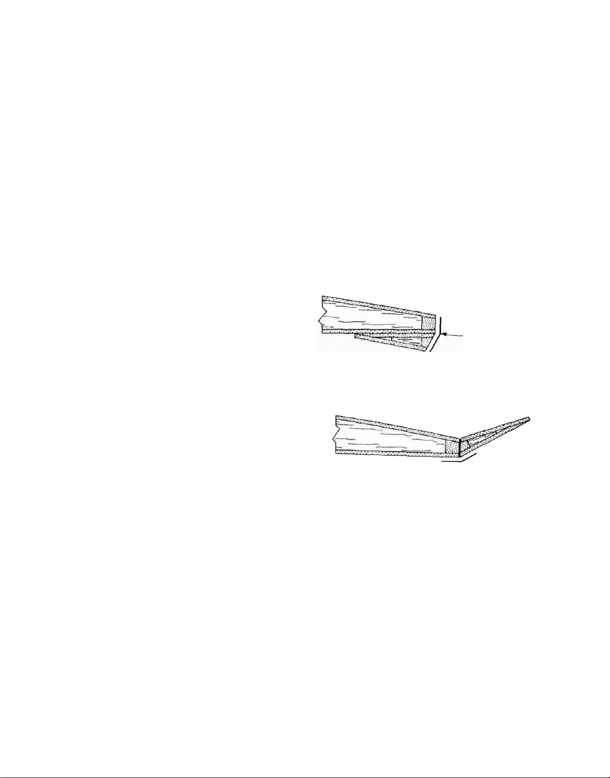
COVERING
The ANTARES lends itself quite well to a fully-Monokoted
finish Monokote will keep the dry, unballasted weight
well within reasonable bounds and this is important
when
working light
that we suggest for both the flaps and ailerons employs
the use of Monokote and this means not only the extreme
effectiveness of these surfaces is enhanced but colors
can be chosen that match the rest of the wing We would
caution you that we have never flown any of the prototypes that did not use the hinging method that we are
showing you in this manual Surface effectiveness would
surely suffer should you decide to hinge the ailerons and
flaps with conventional nylon hinges
Before covering, we suggest that you fully assemble the
airframe and perform a simple balance test This only
involves trying to balance the airframe while it is suspended from the nose bottom and the rear bottom of the
fuselage to see if one side is heavier than the other If,
after performing this test, you find one side definitely
heavier, compensate with a small amount of weight in the
opposite wing panel and re-balance Repeat this process
until you are satisfied This simple step, taken now, can
solve a lot of problems in trim later on
Each of the individual components are now covered,
fuselage, canopy, top hatch, stabilator halves, rudder,
ailerons, flaps and wing panels Follow the instructions
provided with each roll of Monokote Remember, to keep
it
simple, light and beautiful, keep it Monokote.
After covering, clear-out the hinge slots for the fin and
rudder Pre flex these hinges to free up their movement
We like to drill three or four small holes in each side ofthe
hinges first, so that when they are epoxied in place the
adhesive flows through the holes and acts as "pins"
when cured Hinge the rudder to the fin
Next, hinge the ailerons and flaps to their respective wing
panels As you can see from the diagram, this is done in
two steps with full length 1/2" wide strips of Monokote
Since the first strip applied is the inside one, you can
accurately locate the position of the surface to be hinged
with small pieces of light tack draftsman's tape on the
bottom hinge line Now rotate the surface all the way
around to the bottom surface of the wing and apply the
first, inside, hinge strip Remove the tape from the bottom, hold the surface' in the full up position and apply
the second hinge strip to the bottom of the hinqe line As
the plans show, take care to maintain the smallest possi
ble
gaps between each
free movement is maintained)
Locate and carefully clear-out all openings in the fuse
lage, wings, flaps, ailerons and stabs for the various push
rods,
horns,
a little 5-minute epoxy to the inside of the aileron and flap
horn holes Screw the 4 40 flat head bolts (4) in place
from the bottom of each surface—wipe off any excess
glue with acetone The nylon rudder horn is now attached
with the two #2 wood screws provided.
You may have been wondering how the stab halves could
be locked in place if there is only one locking wheel
collar? Sim ple First test fit the stab halves to the fin, make
sure the joiner wires are the correct length to achieve a
good fit to the fin Once satisfied, simply apply a tiny
amount of CA adhesive to oneside of the two joiner wires
(not to the "flat" side of the rear one) and insert these into
antenna and tubes Use
kinds of
surface
lift
Also, the hinginq method
(1/32"
or
less
making sure
a toothpick
to
apply
the right stab half, the one without the wheel collar. Now
the wheel collar can lock the stabs to the fin and you won't
be losing those joiner wires'
Your kit comes with an 11" length of rubber skid material—note that this has a removable backing that protects its adhesive This material can be shaped with
sandpaper, we did this at the nose to "streamline" it a
little We recommend cutting away a 3/8" wide strip of the
Monokote on the bottom of the fuselage where this strip
will be affixed—see plans Attach the strip in place,
ahead of the towhook, on the centerline We might sug-
gest that you drill a small hole in the skid at the very nose
and run a small (3/8" long, would do) wood screw through
the skid and into the noseblock, this anchors it quite well
and avoids "peeling".
HINGE-MAKING PROCEDURE
(SHOWN IN CROSS-SECTION; NO SPECIFIC RIB)
1/2 WIDE STRIP OF
SUPER MONOKOTE.
FULL LENGTH OF
FLAP OR AILERON
ROTATE FLAP (OR AILERON) DOWN TO A"TUCKED
UNDER" POSITION TAPE SECURELY IN PLACE
IRON ON A 1/2" WIDE STRIP OF SUPER MONOKOTE
THAT IS FULL LENGTH OF FLAP OR AILERON.
REMOVE TAPE SWING FLAP OR AILERON UP TO
FULL REFLEX POSITION TAPE SECURELY IRON
ON 1/2" STRIP OF SUPER MONOKOTE ALONG
HINGE LINE, AS SHOWN ABOVE REMOVE TAPE.
DO OTHER PANEL IN SAME MANNER
RADIO INSTALLATION
Assuming that you have followed these instructions thus
far, servo installation should not be a problem Use the
remaining 3/32" x 3/8" ply strip material to make the six
required
cut-outs on the bottom of the fuselage formers are there
to provide passage for the radio's various leads and
plugs We have consistently found that the plug and lead
wires for the flap servo is to short and therefore requires
an extension Start the servo installation with the flap
servo.
As shown on the plans the flap servo must sit on its rails,
on the centerline of the fuselage, with its output arm's
clevis holes lined up with the flap tube exits in the right
and left wing panel roots As previously discussed, this
output arm must also be centered within the oblong slot
in the fuselage sides when viewed from the side IMPOR-
TANT If your radio is not equipped with a servo reversing
15
1-5/8"
long
servo rails
Note
that the
half-round
Page 16

feature, make doubly sure that the flap is installed to
provide the correct throw direction Some healthy dam-
age could be done to the servo and or the airframe if it
moves the wrong way' Once satisfied, route the servo
lead
through
Install the stabilator and rudder servos next If additional
clearance is needed for your output arms the inside of the
fuselage sides at that point can be sligntly routed-out as
shown on the plans. Route the leads into the receiver
compartment.
The aileron servo is next Note that when viewed from the
side (see plans) this servo's output arm is centered within
the 1/4" holes in the fuselage and F-10's When viewed
from the top, the servo is directly in place over the
fuselage center line
*Note
that
with your
cable/connector soldering purposes It will be necessary,
particularly in the flap and aileron servo areas, to cutdown the depth of these holes to achieve all of the desired
movement. This is easily done with a carbide cut off
wheel. Also, the carbide cut-off wheel is perfect for cut-
ting the braided cable supplied, to length As mentioned
-earlier, we use Hams' Stay-Bute solder and Stay-Clean
flux for
connector solder
iron to
ever making a solder connection in or around the
fuselage, protect the surrounding area with scraps of
aluminium foil.
Locate the four nylon flap and aileron horns. Pre-thread
them with a 4-40 bolt and then thread them in place on the
4-40 bolts on the flaps and ailerons Locate them about
1/8" below the top ofthe bolt-end as shown Assemble the
wings to the fuselage with the joiner rods and spring
keeper in place on the wing hook. Start by soldering a
connector to one end of each of the two 48" aileron
cables—these connectors, as shown, should have their
hole depth cut-down to 1/8". Now thread a nylon clevis
onto each of the threaded connectors Install the other
end of these cables into the wing panels, from the fuselage and connect the clevis' to their respective holes in
the servo output arm Now use your radio to check the
movement, left and right, of this connection Once satis-
fied, set the transmitter trims in neutral and make the
all solder
first, put a little
"sweat"
manent solder joints before installing the cable When-
the
fuselage
the
threaded
kit
each has a 5/16"
connections Whenever making a cable/
joint,
always pre-solder the cable
flux
in
the
the
joint.
and
into
the receiver.
brass cable connectors
deep
hole
in the base for
connector
Always check for straight, per-
hole
and
supplied
then use
end
the
outboard aileron cable connector joints Thread the
clevis' in place and connect them to the horns Note that
this connection system provides very fine adjustment
The flap drive cable is made by cutting one of the 36"
lengths provided into two 18" lengths Make all the con-
nections necessary for the flaps in the same manner you
did for the ailerons Note the diagram provided that
illustrates the way we set the transmitter up for the
operation of flaps and reflexing them This system has
proven to be flawless in actual operation.
FOR "DOWN" FLAP DEPLOYMENT-
16
Page 17

The connector for the stabilator servo is next Since this
cable is already in place, it's fairly easy to work with.
Thread a clevis onto a connector and snap the clevis in
place on the servo's output arm. Observe the distance
between the rear end of the connector and the cable tube
end—will the connector contact the tube during the operation of the stab? If so, trim a little length off of the end of
the connector Once satisfied, use a small-tip felt marker
to mark the cable for cutting Carefully cut the cable,
solder the connector in place, re-thread the clevis in place
and set the stab servo for neutral.
Use the remaining 36" cable for the rudder Solder a
connectorto one end of the cable, thread a clevis in place
and install the other end into the fuselage, at the servo
compartment Connect the clevis to the rudder servo, at
neutral trim Thread another clevis onto the remaining
connector and attach the clevis to the center hole on the
rudder horn With the rudder at neutral, use a felt marker
to note the location where the cable should be cut Cut the
cable, remove the clevis from the connector, solder the
connector to the cable, re-thread the clevis in place and
connect to the rudder horn.
Install the receiver by first threading the antenna through
the tube provided and out the exit at the rear of the
fuselage. We used thin foam pads to secure the receiver
in place, on its side as shown on the plans Make all of the
necessary servo connections The switch, as shown
the
plans, is the way we installed it on all of our proto-
on
types This method eli mi nates the need of cutting into the
fuselage sides and is much "cleaner", not to mention
easier.
Note on the plans that we show a SR 900 Mah battery
pack installation Our experience with the prototypes,
with this battery installation has been outstanding This
pack takes about the same space as a normal 450-500
Mah pack, weighs just a few grams more than these
packs, but has about twice the capacity' Believe us, when
you are spending all day at the flying field and running
four servos, it's nice to know you can rely on your power
source'
Install the battery pack in the nose compartment Thread
the lead and plug through F-3 to the switch Don't pack
the batteries in place yet, do it after you have determined
what is needed in the way of nose weight for balance.
If you are using a releasable towhook, all of the connections can now be made except for the final one to the
stabilator output arm This last connection is made after
the hand gliding phase and before actual launch
The
radio system should now be tested Look for any
"binding" or interference to the operation of the servos—
correct it now The control surfaces are now set up for the
correct amount of movement or "throw" The following
is what we recommend, based on our prototypes and the
way we like to fly We suggest that you at least start with
these surface throws and adjust as needed after some
flying
experience:
AILERONS
..... 1/2"
up—1/4"
down
(see
plans)
FLAPS .............60 down—10 up (see plans)
RUDDER,
UNCOUPLED
......
1-3/4" each
direction 3-1/2"
total
RUDDER, COUPLED
W/AILERONS
.......
1-1/4"
each
direction
2-1/2"
total
STAB (MEASURED AT
LEADING EDGE) ...
3/4"
up
1/4"
down
1/2"
PRE-FLIGHT
1. CENTER OF GRAVITY (CG)- This is a most, if not the
most important aspect of correctly setting-up this or
any other sailplane The CG shown on the plans—
3-3/16"
behind
the leading edge
of
the
wing—has
proven to be ideal on our prototypes. We would
caution you not to go aft of this point until such time
as you are familiar with the way the airplane flies.
And this is most important, do not attempt to locate
the towhook further aft than the CG We made a
simple device for balancing our airplanes that you
might want to try It was made with two 10" dowels,
1/4" dia. These were "capped" with pencil erasers and
mounted on a hardwood base which was pre-drilled
for the dowels with a 3" spacing With such a device,
very accurate balance can be achieved.
Add small amounts of lead sheet or shot in front of
and/or beneath the battery pack until balance is
achieved and the airplane rests at level on the balancing device. Our prototypes have shown that very little
lead is needed to achieve balance. The lead should be
securely but not permanently installed in order to
make/changes neededlater.
2. RADIO AND AIRFRAME INSPECTION: Once
again,
check the radio system to be sure that the surfaces
move in the desired direction by radio command and
that the action of the servos is smooth and bind-free.
If you have installed a captive towhook system, test
its operation to be absolutely sure of release on
command
Take the time to inspect the airframe and its various
components Check for warps, looseness of any kind,
etc...Now is the time to correct these kinds of problems, not at the flying field. Make sure your radio
system's batteries are fully charged and head for the
flying site.
FLYING
From time to time we have heard that this individual or
that individual does not believe in hand-gliding a new
sailplane. We are told that these people simply hook the
airplane up to the launching system and "go for it" We
would have to advise you that this is not recommended.
as far as we're concerned. Let's try a few hand-glides first.
Assuming that the C G is right and that the radio is on
and functioning, set all of the controls for neutral, zero
flaps and all othertnms in neutral Hold the airplane at the
fuselage, just beneath the wings, over your head. Run or
trot into the wind until you feel the airplane getting
"light" at which time throw it straight and smoothly,
slightly nose down with the wings level The airplane
should glide straight forward at a very flat angle. Try to
remember what commands you felt that you had to give
it to keep it straight, if any. Before making any (-
corrections repeat another hand
glide
if they are truly necessary Now make any changes to the
trims that you felt were needed and hand-glide once
again This process should be on-going until you have
achieved the long, flat, straight glide that is desired. You
can now hand-launch the airplane a little harder, flatten-
ing it out at the top of its climb and get a little experience
17
total
Page 18

with the flaps The first thing that you will find is that very
little flap deployment is needed to produce a major
reduction in airspeed Some increase in altitude will
occur
but it tends to be very gentle with thisdesign Full
deployment of the flaps—max travel—will almost stop
the plane
Experimenting with this characteristic will soon demon-
strate that very
slow landing approaches can be made You will also find
that suddenly returning the flaps to neutral will result in a
rapid increase of speed and loss of altitude until neutral
trim cruise speed is again reached If your experience is
anything like ours, you will start to think of flaps in the
same sense that you would think of "throttle" on a power
ship.
So far, so good You should have at least a little experi
ence in the use of the flaps in their normally deployed
use. Try a good, hard hand launch at neutral trim and
establish normal glide speed as soon as possible Once
normal cruise speed is reached, move the flap trim lever
up a little to introduce some "reflex" into the flaps and
watch what the airplane does carefully What should
happen is a rather quick acceleration resulting in an even
flatter and much faster glide As mentioned earlier, most
radio systems and their servos have enough travel in just
the trims to provide about 10 of reflex to the flaps Thisis
about twice
plentyYou
ity is of tremendous value in your normal fiying It gives
you the ability to leave "sink" or down air at very high
speeds without sacrificing much in the way of altitude
We have also used it to good advantage in contest situa-
tions by being able to work lift at rather far distances or
low altitudes and still being able to make it back to the
spot.
The next step is actual launch If you are using a Hi Start
system you are going to want about 6-8 lbs of tension or
whatever you are comfortable with on aircraft this size
Turn the radio
tow ring onto the hook With the wings level and the nose
pointed a
brisk throw.
rotate into a 60° to 70° climb As it approaches the top of
its climb, return the flaps to neutral, hold a little down
elevator to
launch height,
the tow instantly and climbing, at the top of the climb,
flatten it
Try to get familiar with the controls while you are at
altitude Does the airplane turn well or do you need more
or less rudder coupling Assuming all is well, use the
altitude to get a little more familiar with the flaps and
what they are doing at various settings Assuming that
you did your homework and that the hand-glides paidoff, right about now you should be enjoying the flight
How does the stab feel? Too much, too little? Try to
remember these
in mid-air, flight speed will be at a walk
as
will
eventually
on,
few
degrees
The airplane
accelerate
pull
out
and
smooth,
much
drop
full
start
things for correction after you land.
highly
as
is
find
the flaps about
up,
and
up elevator This
your
controlled and extremely
really
launch the ANTARES
should
as
flight.
needed, 5 would
that this reflexing capabil-
accelerate quickly and
you
pass over
15°
and
the
should
hook the
with
top
of the
get
you
be
off
And speaking of landing, it's about time for one. We
would suggest that first landings with the ANTARES be
made just as you would any other sailplane To safely
slow the airplane down during these initial flights, try
dropping the flaps just a little on the downwind leg. This
slows it down consistently so that turning upwind to final
approach it will be more than manageable As experience
builds you will develop your own sequence of landing
approaches
This next launch assumes that you are somewhat comfortable, in that the airplane is adequately trimmed, at
least for now Use the same launch sequence as outlined
earlier and start looking for lift We think that one of the
outstanding characteristics of the ANTARES is the way it
reads lift The airplane flies so smoothly that when lift is
encountered it really tends to let you know, right away.
Wings "rock", the tail "lifts", even in light lift the smooth-
ness of the flight is interrupted with tell tale movement
that is easily seen from goodly distances Interestingly,
we have found that in heavy lift the deployment of the
flaps is just not needed and have even gone as far as to
increase the flight speed with reflex in such conditions.
Just keep the airplane moving at flight speedand turning
smoothly and up you go
introducing some deployed flap is of realvalue in taking
advantage of anything available In these conditions the
rule is still the same, keep the airplane moving and
turning smoothly When sink or down air is encountered,
you should not linger in the area and the rule is get out of
there quick at either hard right or left angles or punching-
out further upwind at the fastest possible speed In this
situation try a little reflexed flaps—it is really amazing
how quickly you can get from A to B.
We sincerely hope that the ANTARES has been a re-
warding project for you and that the hours spent on the
building board will be nothing compared to the hours of
soaring enjoyment to come Speaking of soaring enjoy-
ment, TOP FLIGHT MODELS, INC is happy to offer you
the attached information and membership declaration
for the world's largest R C sailplane organization, the
a
LEAGUE OF SILENT FLIGHT Your R/C soaring activities
can take on a whole new meaning and importance by
participating in the LSF's Soaring Accomplishments
Program
INDEX
INTRODUCTION
PRE-CONSTRUCTION
F3B
MODIFICATION SUGGESTIONS
FUSELAGE ASSEMBLY . ......................
TAIL
GROUP
BALLASTING .. ................................
WING ASSEMBLY ..... .......................
COVERING
RADIO INSTALLATION
PRE-FLIGHT
FLYING . .
LS.F. APPLICATION .............................
........ ............
ASSEMBLY
.................................... 15
.......... ......................... 17
....
In
light
lift
wehavefound
NOTES
.......................... 15
. ........
...................
.............
........................
.............. 17
that
1
2
3
3
8
10
10
19
18
Page 19

LEAGUE OF SILENT FLIGHT
P.O
Box
647
Mundelein, Illinois 60060 USA
Hello...
You're in good company if you're curious about the LSF Many are these days. The LSF is attracting the
attention and interest of R'C sailplane enthusiasts throughout the world.
The League of Silent Flight is an association of and for 'he individual sportsman It is not a club. . it is a
program and participation neither conflicts with nor requires club membership However, many clubs
find that group participation in the LSF can excite new interest and bring new growth.
Membership can only be earned Membership cannot be bought there are no membership dues or
fees To become a member, an R C sportsman must fulfill the requirements of Level I of the LSF Soaring
Accomplishments Program a 5 minute thermal flight, a 15 minute slope flight or a second 5 minute
thermal flight, and five spot landings within 3 meters (9 84 feet) of a target point
Advanced levels in the program are progressively n e challenging Level V, for example, requires a 2
hour thermal flight, an 8 hour slope flight, a 10 km (6.21 mile) goal and return flight, as well as
considerable success in soaring competition
Members (sportsmen who have achieved Level I or higher) are privileged to display the distinctive LSF
insignia The
LSF
emblem on a jacket
or
sail
plane
is a symbol of proven performance It
is
displayed
with
pride and recognized anywhere in the world
The LSF is a personal challenge, and serious sportsmen are invited to associatewith the League. The first
step? Declare your intent.
To LSF Executive Board
P.O
Box
647
Mundelein, Illinois 60060 USA
I.
_______________________________,
(please
print)
will
support
the
philosophies,
concepts and criteria set forth in the Bylaws of the League of Silent Flight and give notice herewith of
intention to
attain
Level I of
the
LSF
Soaring Accomplishments Program, and by so
doing,
earn
full
recognition and privilege of membership
(Signature)
Mailing
Address.
__________________________________________________
————————————————————————————^—————————————————————
AMA
FCC
(or other)
(or other
FAI
Affiliate)
Radio
Operator's License No.
License or
Membership
No.
____________________________
__________________________________
NOTE: ALL CORRESPONDENCE TO THE LSF MUST INCLUDE AT LEAST $1 00
IN STAMPS OR COIN FOR RETURN POSTAGE
19
 Loading...