

Page 1
BUILDING
THE
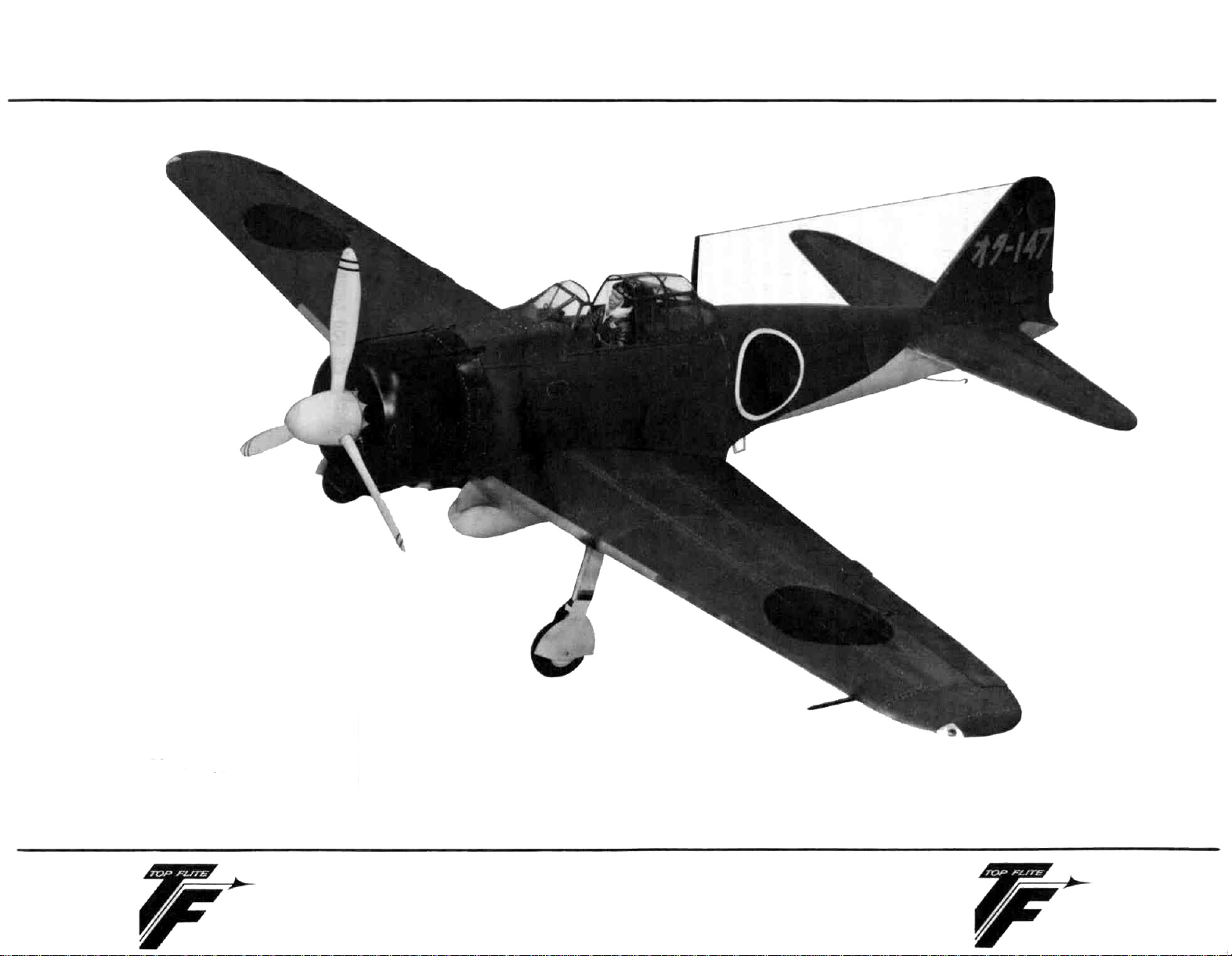
A6M2
ZERO
Product Support
(Do Not Remove From Department)
TOP FLITE MODELS, INC
Page 2
CONGRATULATIONS'
You now own the most accurate
produced
We
at Top Flite hope that you will find this model the most
pleasant to build, inspiring to look at and exciting to fly that you
have ever constructed
It
is honest to point out, however, that while this model is
more difficult - in fact is simpler than most comparable kits to
make,
R/C
scale models generally are not for the newcomer to
this hobby Previous modeling experience and careful attention to
craftsmanship are necessary Even the "old hand" will do well to
study and follow the instructions and guidance given in this booklet.
It is-our aim to have you say "This is the finest model I have ever
built".
CONSTRUCTION OF THE A6M2 ZERO
BEFORE YOU START, READ THIS
The assembly sequence of your Top Rite
fully developed to help assure the correct alignment of your model
Utilize the check-off blocks as you build this will allow assembly
of your model in minimum time
Before beginning an assembly step, read the instructions to fami-
liarize yourself with the parts to be used Find the parts mentioned and double check them for proper identification and size with
the plans Do not separate parts from the die cut sheets until you
need them There are machined parts in the kit which are not
identified such as the leading edges, wing tips, etc These parts
can be easily identified by checking the parts against the plan.
We are sometimes asked which glues are best for model construction The answer to this depends upon the particular job This is
our normal recommendation For all hardwood to hardwood or
hardwood-to balsa joints, use white
especially good, as it dries faster than other white glues and is very
strong For balsa-to-balsa joints, regular balsa-wood cements are
ample for the job, although white glue can be used here too.
Whichever type you use, remember that excess glue is no substitute for a well fitting joint Use a minimum of glue at all times,
and wipe off excess glue that squeezes out of joints before it sets
hard, when set it is difficult to remove, but if not removed it
could spoil the covering job.
R/C
Stand-Off Scale kit ever
TOP FLITE MODELS. INC
ZERO
has been care-
wood
glue
"Titebond"
no
is
USE COMMON SENSE
When you have completed this model, you will have invested
considerable time, money and skill Protect this investment by,
1. Re-checking all critical building points (center of gravity,
hingeing of control surfaces, strength of stress areas, etc ).
2. Correctly installing the radio gear
3. Test and re-test the radio, all moving surfaces, landing gear
(if retracts), condition of batteries, etc.,
FLIGHT!
4. OBSERVE ACADEMY OF MODEL AERONAUTICS SAFETY
CODE, particularly those rules governing RADIO CONTROLLED FLIGHT DO NOT FLY WITHOUT BEING FULLY
INSURED
WARNING!!
A radio controlled model is not a "TOY" Care and caution
must be taken in properly building the model as well as in
the installation and use of the radio controlled device It is
important to follow all directions as to construction of this
kit as well as installation and use of the engine, propellers
and radio gear The advice and assistance of a well experienced builder and pilot is highly recommended Don't
take chances Improper building, operation or flying of
model could result in serious bodily injury to others, your-
self, or property damage
BEFORE EACH
CONSTRUCTION
SEQUENCE
Follow each step in order and put check marks in
the blocks as you complete each phase described.
IMPORTANT NOTE TO BUILDER
Every model built from a kit is different, reflecting the level of
skill as well as the favored building techniques of the modeler
ultimately thus, each model is essentially the individual creation
of
that builder.
Changes and variations take place in building so that while Top
Flite supplies most essential building materials, the end product
is the creation of the builder
Therefore, Top Flite assumes no responsibility for the performance of the model, nor does Top Flite assume any responsiblity
of any nature whatsoever for the loss of, or property damage
resulting from the operation of this model when it is completed
1
The fuselage plans come in two sheets The smaller
must be cut along the dotted line and glued (or taped)
to the larger plan at the dotted lines Before you do
any building of this kit, we suggest you spend a few
hours reading and studying this book and the plans.
When you are ready, tape or tack the fuselage plans on a
flat
work
surface
MonoKote backing or waxed paper
Cover
the
working
area
of
the
plan
with
Page 3
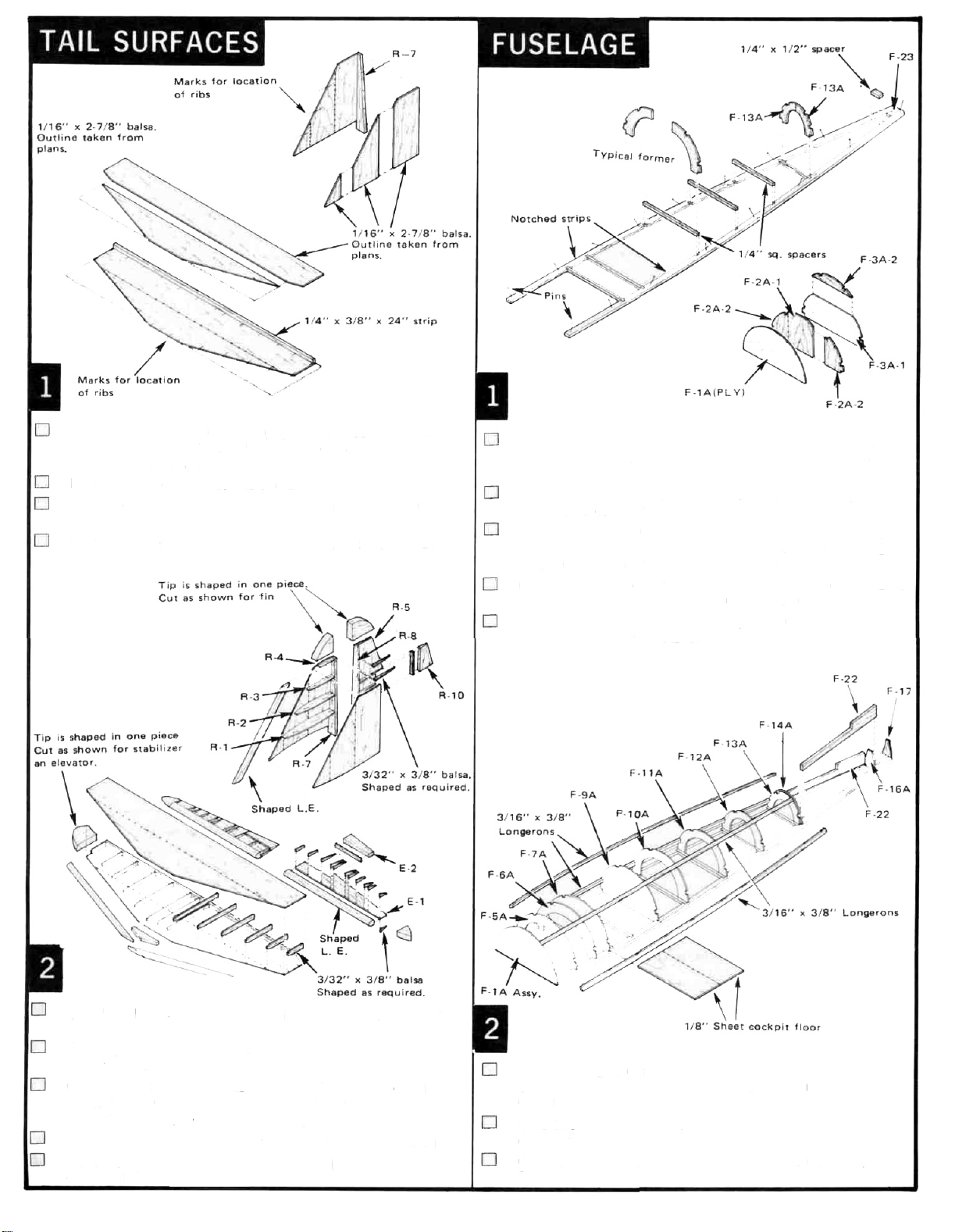
Trace pattern of Fin sheeting (3 pieces on each side) from
plans onto 1/16" x 2-7/8" balsa. Cut out and glue together
as shown above. Make two.
Do same thing with Stabilizer. Make two.
Pin Fin sheeting over plan. Glue
of ribs with soft pencil.
Pin Stabilizer sheeting over plan. Glue
in place. Mark location of ribs with soft pencil.
R-7
in place. Mark location
1/4" x 3/8" x 24"
Glue
F-2A-2's to F-2A-1 and F-3A-2 to F-3A-1.
F-1A(PLY),
together.
Glue former halves
to measure correct width.
Pin notched strips (sometimes referred to as "crutch strips")
down over plans, locate from inner line as the outer edge
of the strip will be trimmed off later on.
Measure, cut and glue 1/4" SQUARE spacers in place. Glue
1/4" x 1/2" SPACER and
Glue formers F-5A thru F-14A in place.
are perpendicular to notched strips.
F-2A ASSEMBLY and F-3A ASSEMBLY
F-5A thru F-16A
F-23
together, using plans
in place at rear.
Be sure formers
Epoxy
all
Glue R-1.
to 1/4" from front of rib.
Glue top sheeting in place. Again apply glue only up to 1/4"
from front of rib.
Glue shaped leading edge to ribs only. When dry, glue planking to leading edge on both sides. Be sure that the planking
forms to the shape of the leading edge.
Construct rudder as shown in illustration above and the plans.
Make stabilizer and elevators using same procedures as is
described
R-2. R-3
above._______
& R-4 ribs in place. Apply glue only up
Glue two
of notched strip. Glue F-16A to F-22's and notched strip.
Glue F-17 in place.
Glue two pieces of
cockpit floor.
Glue four
formers.
F-22's
in place so they are 1/16" from outer edge
1/8" SHEET together and cut to fit for
3/16" x 3/8" LONGERONS
into notches in
Page 4

Trim and glue a
fuselage between the notched strip and first longeron.
Fit and glue a 1/8"
next two longerons, on each side. Wood can be formed to
compund
pins, tape and/or rubber bands while glue is drying.
Finish top with 1/8" x 3-3/4" (or 4") x 24"
opening at cockpit area. (F-7A to F-9A).
All seams should be in the approximate center of each longeron. Allsheeting is done on a "Fit and try" basis.
1/8" x 7/8" x 30" STRIP
x 2-7/8"(or 3") x 30" SHEET
shape
by
wetting
outside
to each side of
only.
Hold
between
in
place
SHEET.
with
Leave
Laminate F-1B(PLY),
for F-1A assembly. Set aside to dry.
Epoxy F-19(PLY) doublers to insides of F-18 pieces.
Glue formers
in the two F-18 pieces.
Epoxy 1/2" x 1-1/8" MOTOR MOUNTS to the insides of
F-18's and F-5B and F-6B as shown. Motor mounts are to
extend out 4-3/8" from ends of F-18's.
Cut 3/8" x 1-1/8" x 1-1/2" long maple block in half to make
two pieces 3/8" x 3/4" x 1-1/8". Epoxy these pieces into
the cut-outs in the F-19(PLY)'s.
F-5B. F-6B. F-7B, F-8B and P-9B
F-2B and F-3B
firewall as described
into the slots
Cut notch in rear center of stabilizer for clearance for elev.
control horn movement (see plan).
Epoxy elevator control horn to stabilizer at BRASS TUBING
ONLY!
Epoxy stabilizer to fuselage. Check alignment in all direct-
ions.
Cut hole in stab planking for fin leading edge and epoxy fin
place. Check alignment in all directions.
Drill holes for control horns in rudder and both elevators.
and then "Vee" notch. Make openings for plastic hinges.
Attach rudder control horn to rudder with epoxy. Attach
rudder to fin and epoxy brass tubing (only) to rear of fin.
Attach elevators to stabilizer.
Glue
R-9
in place. Fit
each side of rudder. Shape as required.
5/8" x 1-3/8" FILLET BLOCKS to
3
Fuselage can be removed from plans.
Carefully position wing saddle assembly in position on in-
verted fuselage half and glue.
Epoxy former F-4B to front of wing saddle, to notched
strips and to motor mounts. Epoxy F-1B Firewall assembly
over motor mounts and to F-1A assembly. Make sure firewalls are flush and true in both planes. Epoxy motor mount
support blocks in place.
Make and glue all remaining formers
position on notched strips. Glue 3/16" x 3/8"
in place[F-1B assembly to F-4B and F-10B to F-15B(or
F-16B)].
Bend TAIL WHEEL WIRE as shown on plans. Over the
straight end, assemble a collar, the nylon tailwheel bracket,
F-20(PLY)(after drilling hole) and another collar.
Make two supports for F-20(PLY) from scrap 1/8" balsa and
glue into position. Cut the 3/8" x 5/8" x 3-1/2" long balsa
block into two pieces to fit in between F-16B and F-17.
Glue the pieces in place and rouqh to shape only.
(F-10B thru F-16B) i
LONGERONS
n
Page 5

Install elevator and rudder servos. Make and rudder pushrods.
Check all control surfaces for free and proper operation. Safety
all clevises now as they are hard to get at once the fuselage is
entirely sheeted.
Glue 1/8" x 7/8" x 42"
Fit, form and glue 1/8" x 2-7/8"(or 3") x 42" SHEET next to
7/8" wide pieces.
Pit, form and glue
opening.
When shells are dry, trim carefully around wing opening. Plank
(cross grain) openings from over formers F-4B thru F-10B with
1/16" balsa sheet.
Glue
1-1/8" x 2-1/2" x 2-3/4" TAIL BLOCK
Carve and sand to shape. Sand entire fuselage, cutting down
raised
edges
of notched
For access to interior of fuselage, cut out formers
F-7B, F-8B and F-9B from between F-18 pieces.
BALSA
1/8" x 3-3/4"(or 4") x 24" SHEET
strip
to each side as shown.
until
flush
with
sheeting
in position.
F-5B, F-6B,
in last
Glue
W-3B(PLY)
left hand and one right hand.
Glue W-5B(PLY) and W-5C(PLY) to W-5 RIBS. Make one
left hand and one right hand.
Cut four pieces of 1/4" x 1/2"
long. Taper one end of each piece as shown.
Glue these strips to 1/4" x 1/2" x 30" SPARS, 15-1/8" from
one end of each strip as shown. Leave excess length on spar
to aid in pinning down. Make four sets.
and
W-3C(PLY) to W-3 RIBS.
BALSA
Make one
strips to 12-9/16"
Tape 4 pieces
3/32" x 2-7/8" x 15" BALSA
two sets.
Turn them over, open up slightly, and apply glue to joints. Lay
on flat surface, with weights, until dry.
Cut a triangular piece, as shown shaded above, off of each
piece and SAVE.
Make two more sets, using the triangle, three 3/32" x 2-7/8" x
30" and two 3/32" x 2-7/8" x 15" for each set.
of 3/32" x 2-7/8" x 30"
together as shown above. Make
Balsa
and
two
pieces
of
Cover wing plan with MonoKote backing. Pin one assembled
over outline on plan.
Glue ribs W—3 thru W—11 to spar, pinning thru feet of ribs,
checking to be sure ribs are perpendicular.
Glue
W—22
to
front
of
each
rib
and
pin.
Glue
7/16" THICK x 28" LONG TAPERED
ribs and pin.
Glue upper spar in position in rib notches.
When wing is dry, take DIHEDRAL GUIDE as shown above,
mark lines and cut off spars, W—22 and trailing edge. Unpin
from plan.
Build opposite wing panel in exactly same manner.
piece to back of
4
Page 6

Leave last wing panel built pinned to work table. Join wing
halves together using
epoxy. Block up opposite wing panel for correct dihedral.
Epoxy
W-17(PLY)'s
Crack W-13(PLY) and W-14(PLY) in center to conform to
angle of leading edge. Epoxy in place as shown.
Shape
17/32" x 1-3/16" x 7"
shape of trailing edge. Epoxy in place. Epoxy W—18(PLY) to
this block.
Glue
two
W-1A's
place in wing as shown.
Assemble
as shown above. Filler wedges are made from scrap balsa.
HARDWOOD BLOCK,
W-16(PLY) JOINERS and
to W-16(PLY)'s.
and
two
BALSA
W-1B's
BLOCK
together.
W-2D's,W-19's and W-3D's
slow drying
to
conform
Epoxy
them
to
in
Glue
W-21
to center of 3/4" face of 3/8" x 3/4"
Mark location of each rib from the plans. Cut 3/32" x 3/8"
BALSA
and bottom. When dry, taper ribs with sandpaper block or
razor plane. Make two ailerons.
Bevel front of leading edge as shown. Install three
HINGES.
Glue W—28(PLY)'s in place top and bottom. Location of
W-28(PLY)'s determine L.H. or R.H. aileron. Make one each.
Install NYLON HORNS with #2-56 x
to length for each rib, and glue them in place top
See plans for instructions.
1/2" R.H.M.S.
STRIP.
NYLON
Glue
W-2C
length
is to be used).
Epoxy
for spacing. Install servo(s).
Make
are recommended at servo end).
Glue
Mount
and epoxy this assembly on W—8B and W—9B.
Plank top of wing panel that is still pinned down.
Remove wing from bench and pin down opposite wing panel.
Repeat planking procedure on this panel. Unpin and remove
all rib feet.
in place on W-2B rib. Cut out one W-1B to same
as
W-2C
as
shown
above
(both
W—1A'S
1/4" x 3/8" SERVO RAILS
CONTROL WIRES
W-8B
in place on W-8 rib. Glue
BELLCRANK ASSEMBLY(see
as shown above (ball link connectors
in place using servo as guide
W-9B
plans) to
5
if
flap
in place.
W-12(PLY)
servo
Epoxy
L.G. KEY BLOCKS
L.G. BLOCK in rib notches. Locate from plans. Drill 7/32"
dia. hole to line up with groove in key block
Locate and cut openings for control wires and main L.G.
wires, in wing planking. Plank both bottom wing panels.
Glue WING TIP blocks together and saw to outline. Glue
wing tips to wings, and shape.
Shape leading edges per plan. Sand wing all over.
Hinge
ailerons
ating, hinge them permanently, otherwise cement them in
place. Connectcontrols to ailerons (and flaps).
permanently
to W-3 ribs. Epoxy
to
wing. If
flaps
are
GROOVED
to
be
oper-
Page 7

Temporarily center the REAR COWL on fuselage so that the
mounting holes are at 45° to the vertical and horizontal center
lines
of
the
fuselage
Remove cowl and drill
Drill a 3/16" dia hole in the center of each F 23(PLY)
piece
Press a #4—40
Fasten
the
R H M S Use the F 21 (PLY) with blind nut inside the
fuselaqe
rear
Mark location
1/8" DIA
blind
cowl in place
of
holes
holes thru at marks
nut
firmly
in
with
four
#4-40 x
with
each
soft pencil
one
3/4"
Drill 1 /4" dia x 1 3/4" deep hole in leading edge in center of
wing Install
Dowel should stick out at least 1/4" Sand slight radius on
end of dowel
Epoxy face of
away from wing Do not get epoxy on dowel Put the wing
with F—21 (PLY) in place on the fuselage and align carefully
Temporarily fasten it down This will correctly locate the
F-2KPLY) on the fuselage
When the epoxy has set and while the wing is still fastened
down, drill two 1/8" DIA holes thru wing and thru fuselage
blocks See plans for location dimensions
Glue F-10C to wing only(not to fuselage) Glue
wing See plan for location Make two cross pieces from scrap
1/8" stock Sheet over this area with 1/8" soft sheeting
Remove
screw
furnished
screw clearance Cut notches in planking for screw head
clearance
1/4" DIA x 2" LONG DOWEL
F—21
(PLY) and slip over dowel with epoxy
wing
Tap
fuselage
Drill
holes
wing holes
with
out
#8-32
to
11/64"
with epoxy
F—9C
on
self
tapping
DIA
for
With wing bolted in place, form and fit wing fillets
W-24 and W-27 All fillets on each side of the wing must
be done at the same time for proper fitting W 23's are
fixed to the wing while W 24 and W 27 are fixed to the
fuselage Smooth joints with Dap
Drill holes in firewall at proper locations for throttle and
mixture controls and fuel line Install engine— 60 to 90 recommended Attach fuel line Install throttle and fuel mixture
control cables Check for free movement
Install the radio equipment (receiver, battery, servos, etc ) as
per the manufacturers instructions
Make cut outs in
Cement to rear cowl and sand lightly with 400 grit paper
prior to painting
Attach
W-26(PLY) L.G DOORS
as shown on plans , Install main wheels and tail wheel
Cover the model (except cowl) with colored
or cover the model with
color desired and then scribe panel outlines
Paint cockpit with flat black Install pilot (not furnished) Trim
and install vacuum formed gun ports and canopy See plans for
adhesives to use Apply markings furnished
Check radio carefully, including range check per manufacturers
instructions Check Center of Gravity Do not deviate from
position shown on plans If you are not a proficient R/C pilot,
get the help of one
avoid grief
FRONT COWL
CHROME MONOKOTE,
See
warning
for exhaust, glow plug, etc
on
to main landing gear wire
MonoKote,
page 1 Save
W-23,
paint as per
your
plane-
or
This plane is designed to have operating flaps if desired The flaps
will have to be hinged and control horn added, instead of fastened
solid as shown on plans Provisions have been made in the wing
for the additional servo The decision to have operating flaps must
be made before the wing construction is started
Again the decision to use landing gear retracts must be made before
construction begins Construction provisions have been built into
the model for retracts There is room in the center of the wing,
foreward of the main spars, for a servo (mechanical retracts) or a
servo and valve (pneumatic retracts) The air supply tank (pneum
system) is located in the fuselage Be sure the tank(s) and air lines
DO NOT INTERFERE with the pushrod operation The model
can be balanced with the wheels up or down as the fore and aft CG
remains the same
6
Page 8

For a 16-page catalog plus a free MONOKOTE™
sample and prop chart, send request
plus 50 cents to Top Flite
© Top Flite Models, Inc. 1981 150308'
 Loading...