

Page 1

INSTRUCTION MANUAL
Top Flite Models Champaign, IL
Ph: (217) 398-8970, Ext. 5
Fax: (217) 398-7721
airsupport@top-flite.com
WARRANTY
Top Flite® Model Manufacturing Co. guarantees this kit to be free from defects in both material and workmanship at the date of purchase. This warranty does
not cover any component parts damaged by use or modification. In no case shall Top Flite’s liability exceed the original cost of the purchased kit. Further,
Top Flite reserves the right to change or modify this warranty without notice.
In that Top Flite has no control over the final assembly or material used for final assembly, no liability shall be assumed nor accepted for any damage resulting
from the use by the user of the final user-assembled product. By the act of using the user-assembled product, the user accepts all resulting liability.
If the buyer is not prepared to accept the liability associated with the use of this product, the buyer is advised to return this kit immediately in new
and unused condition to the place of purchase.
To make a warranty claim send
the defective part or item to
Hobby Services at this address:
Include a letter stating your name, return shipping address, as much contact information as possible (daytime telephone number, fax number, e-mail address), a
detailed description of the problem and a photocopy of the purchase receipt. Upon receipt of the package the problem will be evaluated as quickly as possible.
READ THROUGH THIS MANUAL BEFORE STARTING CONSTRUCTION. IT CONTAINS IMPORTANT INSTRUCTIONS AND WARNINGS CONCERNING THE ASSEMBLY AND USE OF THIS MODEL.
Entire Contents © 2014 Hobbico, Inc. TOPA1956
Hobby Services
3002 N. Apollo Dr. Suite 1
Champaign IL 61822 USA
Page 2
INTRODUCTION
Top Flite is very proud to bring you the giant scale Zero.
The Zero became one of the most important fi ghters of
World War II. You will enjoy using this scale accessory
to add to the overall look and enjoyment of your Zero.
Mail parts orders Hobby Services
and payments by 3002 N Apollo Drive, Suite 1
personal check to: Champaign IL 61822
Be certain to specify the order number exactly as listed
in the Replacement Parts List. Payment by credit card
or personal check only; no C.O.D.
KIT CONTENTS
REQUIRED FOR COMPLETION
❍ 1- Futaba S3102 Servo 50 oz. in. of torque
(FUTM0034)
❍ ½ oz. Medium Pro CA+ (GPMR6009)
ORDERING REPLACEMENT PARTS
Replacement parts for the Top Flite Giant Scale Zero
ARF are available using the order numbers in the
Replacement Parts List that follows. The fastest, most
economical service can be provided by your hobby
dealer or mail-order company.
To locate a hobby dealer, visit the Top Flite web
site at www.top-flite.com. Select “ Where to Buy” in
the menu across the top of the page and follow the
instructions provided to locate a U.S., Canadian or
International dealer.
Parts may also be ordered directly from Hobby Services
by calling (217) 398-0007, or via facsimile at (217) 398-
7721, but full retail prices and shipping and handling
charges will apply. Illinois and Nevada residents will
also be charged sales tax. If ordering via fax, include
a Visa® or MasterCard® number and expiration date
for payment.
If additional assistance is required for any reason
contact Product Support:
by e-mail at or by telephone at
productsupport@top-fl ite.com (217) 398-8970
REPLACEMENT PARTS LIST
TOPA1956 . . Giant Zero Drop Tank
Complete Parts Set
TOPA1949 . . Giant Zero Drop Tank Release Set
TOPA1948 . . Giant Zero Drop Tank Set
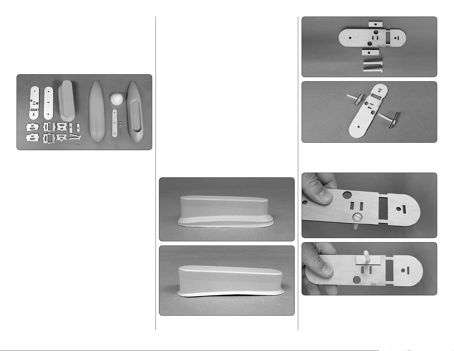
ASSEMBLE THE
DROP TANK MOUNT
1. Locate the ABS drop tank mount. Cut it as shown.
❏
2
2. Locate the plywood former, plywood mounting
❏
screw doublers and 1/4- 20 2" [ 51 mm] ny lon mountin g
screws. Insert the screws into the doublers.
3. IMPORTANT! When assembling the parts that
❏
follow, pay close attention to the photos. Make sure you
assemble the parts exactly as shown. Place one of the
doublers and screws in place on the former. Center
Page 3
the head of the screw in the hole and then glue the
doubler to the former. Repeat this for the other screw
and doubler.
4. Once assembled the former should look like
❏
these photos.
5. Determine the size of the servo you will use for
❏
your dro p tank rele ase. For our s er vo we ne e d ed to cut
the servo tray on the laser cut lines in the tray. This can
be easily done with a sharp hobby knife. Glue the two
parts of the servo tray together.
3
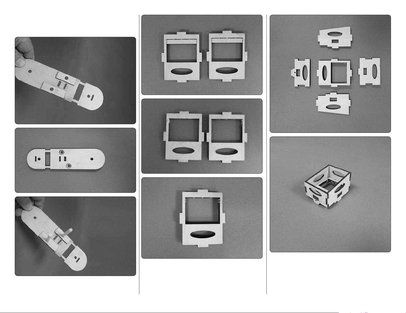
6. Locate all of the plywood parts shown and glue
❏
the parts together forming the servo box. Once again,
pay close attention to the photos to make sure you
assemble the box exactly as shown.
Page 4

Release Pin
Template
7. If you are using the servo we used, Futaba S3102,
❏
the instructions for the release pin that follows will
be correct for this servo. You may need to adjust the
overall length of the pin for your servo choice. From a
2-56 6" threaded wire, bend and cut the release pin
as shown in the sketch.
8. This photo shows the former in the orientation it
❏
will be when it will be glued into the mount. Use the
former as your guide and cut the holes into the ABS
plastic mount as shown. Refer to the photos in the next
step for a reference of what to cut.
9. Glue the former into the bottom of the plastic mount.
❏
For better adhesion, roughen the plastic with some 220
grit sandpaper before gluing the parts together.
10. Install the servo with the screws that came with
❏
the servo. Center the servo and install the servo arm.
4
11. Using a 5/64" [ 2 mm] drill open up the outer
❏
hole in the servo arm. Install the release pin into the
servo horn.
12. Install the servo box into the plywood former
❏
without any glue. Drill two 1/16" [1.6 mm] holes
through the ABS plastic mount into the plywood servo
box. Do thi s on both s i d es of the m ount. Af ter installing
the screws, remove the screws and the mount. Apply
a couple of drops of thin CA glue in the holes. After
the glue has hardened, reinstall the servo box and
the screws.
Page 5

ASSEMBLE THE DROP TANK
1. Locate the parts shown here. Glue the two plywood
❏
plates together. Use the two wood dowels to align the
two plates when gluing them together. Do not glue the
wood dowels to the plates
3. Glue the dowels into the holes as shown.
❏
5. For the next step it will be extremely helpful if you
❏
can either use a servo driver to move the servo arm
during this installation or put a long servo extension on
the servo and plug it into your receiver, allowing you
to use your radio to move the servo arm. Locate the
hard fi ber drop tank retainer. Test fi t it onto the release
pin. The fi ber drop tank retainer should fi t loose on the
release pin. If it is too tight open the hole with a drill bit.
2. Locate the top half of the drop tank. Cut the two
❏
holes and the center slot from the part. These holes
will match with the plywood parts you glued together.
4. Test fi t the plywood assembly into the top half
❏
of the drop tank. Once you are satisfi ed with the fi t,
glue the plate inside of the drop tank. Use some 220
grit sandpaper to roughen the plastic, giving the best
adhesion between the plastic and plywood.
5
Page 6

6. With the fi ber drop tank retainer in place on the
❏
release pin, slide the top half of the drop tank onto the
retainer. When positioning the tank on the retainer be
sure the alignment pins in the drop tank are installed
into the pod. Once you are satisfi ed with the positioning
of the pod, apply a drop of CA glue to tack glue the
retainer to the drop tank. Once the glue hardens operate
the servo several times to make sure the release pin
consistently slides freely into and out of the retainer.
7. When you are satisfi ed with the position of the
❏
retainer, locate two 3/8" 3/8" 9/16" [101014 mm ]
hardwood blo c ks and glue them to t he retain er and th e
plywood former.
8. After the glue has hardened, double check to be
❏
sure the release pin still moves freely in the retainer.
9. Locate the foam drop t ank inser t an d glue it to the
❏
front of the top half of the drop tank.
10. Once the glue has hardened on the foam insert
❏
glue the two halves of the drop tank together, taping the
two halves together while the glue dries. We found that
using white aliphatic glue like RC Z56 glue works well
because it has a long working time, cleans up easily
with water and dries clear.
6
Page 7

11. On the bottom of the wing, under the covering,
❏
you will fi nd two pre-installed blind nuts and an access
hole to feed the servo lead through the wing and into
the fuselage. Cut the covering from these holes.
and rear of the pod. Position the holes you drill so that
you drill into the root rib of the wing. Install and then
remove a #2 3/ 8" screw an d # 2 fl at washer i nto eac h
of the holes you drilled. Remove the pod from the wing.
Apply a couple of drops of thin CA glue into the four
holes to harden the threads.
13. Install a 12" [ 305 mm] servo extension onto the
❏
servo. Secure it with tape, heat shrink tubing or some
other method to secure the leads. Feed the servo
through the wing and reinstall the pod to the wing.
12. Install the pod to the wing with two 1/4 -20 2"
❏
nylon bolts. Don’t worry about feeding the servo lead
into the wing. Make sure you have the pod centered
on the wing. Drill two 1/16" [1.6 mm] holes into the front
7
14. Install the drop tank to the pod.
❏
Page 8

 Loading...