

Page 1
Top Flite Models Champaign, IL Telephone (217) 398-8970, Ext. 5 airsupport@top-flite.com
READ THROUGH THIS INSTRUCTION BOOK FIRST. IT CONTAINS IMPORTANT INSTRUCTIONS AND WARNINGS CONCERNING THE ASSEMBLY AND USE OF THIS MODEL.
TOPZ1020 for TOPA1020 V1.0
Entire Contents © Copyright 2006
™
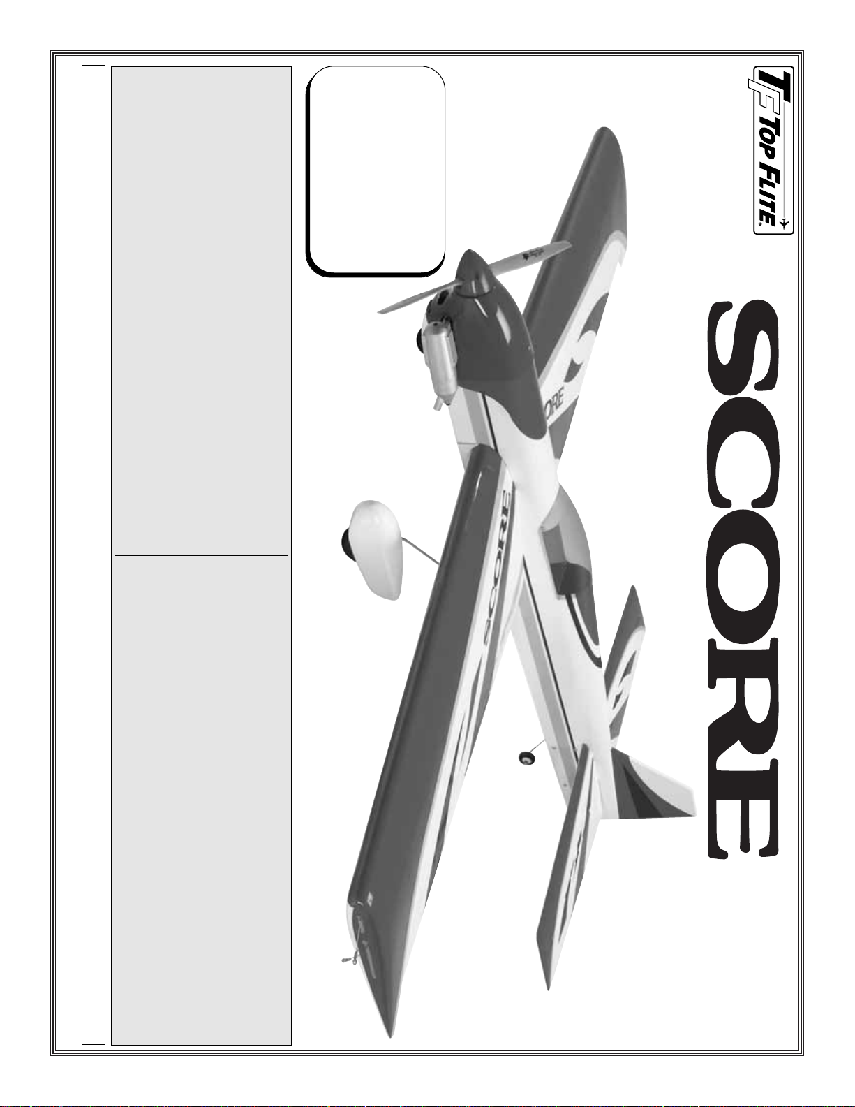
Wingspan: 56.5 in [1435 mm]
Wing Area: 677 sq in [43.7 dm
2
]
Weight: 60-70 oz [1700-1985g]
Wing Loading: 12.8-14.8 oz/sq ft
[39-45 g/dm
2
]
Length: 46 in [1170 mm]
Engine: .40-.51 cu in [6.5-8.4cc]
2-stroke glow control line
WARRANTY.....T op Flite Models guarantees this kit to be free
from defects in both material and workmanship at the date of purchase.This warranty
does not cover any component parts damaged by use or modification.In no case shall
Top Flite’s liability exceed the original cost of the purchased kit. Further, Top Flite
reserves the right to change or modify this warranty without notice.
In that Top Flite has no control over the final assembly or material used for final
assembly, no liability shall be assumed nor accepted for any damage resulting from the
use by the user of the final user-assembled product. By the act of using the user-
assembled product, the user accepts all resulting liability.
If the buyer is not prepared to accept the liability associated with the use of this
product, the buyer is advised to return this kit immediately in new and unused condition
to the place of purchase.
To make a warranty claim send the defective
part or item to Hobby Services at the address:
Include a letter stating your name, return shipping address, as much contact
information as possible (daytime telephone number, fax number, e-mail address), a
detailed description of the problem and a photocopy of the purchase receipt. Upon
receipt of the package the problem will be evaluated as quickly as possible.
Hobby Services
3002 N. Apollo Dr. Suite 1
Champaign IL 61822 USA
Page 2
TABLE OF CONTENTS
INTRODUCTION . . . . . . . . . . . . . . . . . . . . . . . . 2
SAFETY PRECAUTIONS. . . . . . . . . . . . . . . . . . 2
ENGINE & LINE RECOMMENDATIONS . . . . . . 3
ADDITIONAL ITEMS REQUIRED. . . . . . . . . . . . 3
Adhesives & Building Supplies . . . . . . . . . . 3
Optional Supplies & Tools . . . . . . . . . . . . . . 3
KIT CONTENTS. . . . . . . . . . . . . . . . . . . . . . . . . 4
ASSEMBLE THE WING . . . . . . . . . . . . . . . . . . . 5
Install the Flaps. . . . . . . . . . . . . . . . . . . . . . 5
Install Flap Linkage. . . . . . . . . . . . . . . . . . . 6
ASSEMBLE T AIL SECTION. . . . . . . . . . . . . . . . 6
Install Elevators. . . . . . . . . . . . . . . . . . . . . . 6
Install Elevator Linkage. . . . . . . . . . . . . . . . 7
FINISH THE WING . . . . . . . . . . . . . . . . . . . . . . . 7
Test Fit Wing. . . . . . . . . . . . . . . . . . . . . . . . 7
Install Belly Pan . . . . . . . . . . . . . . . . . . . . . 8
Attach Wing . . . . . . . . . . . . . . . . . . . . . . . . 8
LANDING GEAR . . . . . . . . . . . . . . . . . . . . . . . . 9
Assemble Main Gear. . . . . . . . . . . . . . . . . . 9
Assemble Tail Gear . . . . . . . . . . . . . . . . . . . 9
ENGINE AND FUEL SYSTEM . . . . . . . . . . . . . 10
Mount the Engine . . . . . . . . . . . . . . . . . . . 10
Assemble and Install the Fuel Tank . . . . . . 11
FINISH THE MODEL . . . . . . . . . . . . . . . . . . . . 11
Install the Cowl . . . . . . . . . . . . . . . . . . . . . 11
Install the Canopy. . . . . . . . . . . . . . . . . . . 13
Apply the Decals. . . . . . . . . . . . . . . . . . . . 13
GET THE MODEL READY TO FLY . . . . . . . . . 13
Balance the Model (C.G.) . . . . . . . . . . . . . 13
Wing Tip Weight . . . . . . . . . . . . . . . . . . . . 14
PREFLIGHT. . . . . . . . . . . . . . . . . . . . . . . . . . . 14
Balance Propellers . . . . . . . . . . . . . . . . . . 14
Engine Check . . . . . . . . . . . . . . . . . . . . . . 14
Control Check. . . . . . . . . . . . . . . . . . . . . . 14
Adjust Leadouts . . . . . . . . . . . . . . . . . . . . 15
ENGINE SAFETY PRECAUTIONS . . . . . . . . . . 15
AMA SAFETY CODE. . . . . . . . . . . . . . . . . . . . 15
CHECK LIST . . . . . . . . . . . . . . . . . . . . . . . . . . 16
FLYING . . . . . . . . . . . . . . . . . . . . . . . . . . . . . . 16
Flying Precautions. . . . . . . . . . . . . . . . . . . 16
Preflight . . . . . . . . . . . . . . . . . . . . . . . . . . 16
Takeoff . . . . . . . . . . . . . . . . . . . . . . . . . . . 17
Landing. . . . . . . . . . . . . . . . . . . . . . . . . . . 18
AMA STUNT MANEUVERS . . . . . . . . . . . . . . . 19
INTRODUCTION
Congratulations and thank you f or purchasing the Top
Flite Control Line Score ARF.The Score is capable of
performing all AMA stunt maneuvers; however, it is
also a plane that’s suitable even for relative
newcomers to control line flight. The pre-covered
Score assembles quickly and easily with a bolt-on
wing and stabilizer.Access hatches in the tail section
allow elevator control throw adjustment at the field,
and a removable wing tip weight access hatch allows
you to add or subtract tip weight between flights to
fine tune the model. The leadouts can even be
adjusted by a quick turn of a screwdriver. Whether
flown casually or in competition, the Score is sure to
provide you with impressive control line performance.
For the latest technical updates or manual corrections
to the Score Precision Control Line ARF visit the Top
Flite web site at www.top-flite.com. Open the
“Airplanes” link, then select the Score Precision
Control Line ARF. If there is new technical information
or changes to this model, a “tech notice” box will
appear in the upper left corner of the page.
If you have not flown a control line stunt model
before, we recommend that you get the assistance
of an experienced pilot in your club for your first
flights. If you’re not a member of a club, your local
hobby shop has information about clubs in your area
whose membership includes experienced pilots.
AMA
In addition to joining a control line club, we strongly
recommend you join the AMA (Academy of Model
Aeronautics). The AMA is the governing body of
model aviation and membership is required to fly at
AMA clubs. Though joining the AMA provides many
benefits, one of the primary reasons to join is liability
protection. Coverage is not limited to flying at
contests or on the club field. It even applies to flying
at public demonstrations and air shows. Failure to
comply with the Safety Code (excerpts printed in the
back of the manual) may endanger insurance
coverage. Additionally, training programs and
instructors are available at AMA club sites to help
you get started the right way. There are over 2,500
AMA chartered clubs across the country.Contact the
AMA at the address or toll-free phone number below:
Academy of Model
Aeronautics
5151 East Memorial Drive
Muncie, IN 47302-9252
Tele. (800) 435-9262
Fax (765) 741-0057
Or via the Internet at: http://www.modelaircraft.org
PRO TECT YOUR MODEL,
YOURSELF & OTHERS
FOLLO W THESE IMPORT ANT
SAFETY PRECAUTIONS
1.Your Score Precision Control Line ARF should not
be considered a toy, but rather a sophisticated,
working model that functions very much like a full-
size airplane. Because of its performance
capabilities, the Score Precision Control Line ARF, if
not assembled and operated correctly, could
possibly cause injury to yourself or spectators and
damage to property.
2. You must assemble the model according to the
instructions. Do not alter or modify the model, as
doing so may result in an unsafe or unfly able model.
In a few cases the instructions may differ slightly
from the photos. In those instances the written
instructions should be considered as correct.
3.Y ou must take time to build straight, true and strong.
4.You must use lines that are in first-class condition,
and a correctly sized engine and components
throughout the building process.
- 2 -
Page 3
5. You must correctly install all pushrods and other
components so that the model operates correctly on
the ground and in the air.
6. You must check the operation of the model before
every flight to insure that all equipment is operating and
that the model has remained structurally sound. Be
sure to check clevises or other connectors often and
replace them if they show any signs of wear or fatigue.
7. If you are not already an experienced control line
pilot, you should fly the model only with the help of
a competent, experienced control line pilot.
8. While this kit has been flight tested to exceed
normal use, if the plane will be used for extremely
high stress flying, or if an engine larger than one in
the recommended range is used, the modeler is
responsible for taking steps to reinforce the high
stress points and/or substituting hardware more
suitable for the increased stress.
9.WARNING:The cowl and wheel pants included in
this model are made of fiberglass, the fibers of
which may cause eye, skin and respiratory tract
irritation. Never blow into a part to remove fiberglass
dust, as the dust will blow back into your eyes.
Always wear safety goggles, a particle mask and
rubber gloves when grinding, drilling and sanding
fiberglass parts. Vacuum the parts and the work
area thoroughly after working with fiberglass parts.
Remember: Take your time and follow the
instructions to end up with a well-built model
that is straight and true.
Before starting to build, compare the parts in this kit
with the Parts List and note any missing parts. Also
inspect all parts to make sure they are of acceptable
quality. If any parts are missing, broken or defective, or
if you have any questions about building or flying this
airplane, please contact Top Flite at the address or
telephone number below. If requesting replacement
parts, please provide the full kit name (Score Precision
Control Line ARF) and the part numbers as listed in the
Parts List.
Top Flite Product Support:
3002 N Apollo Drive Suite 1
Champaign, IL 61822
Telephone: (217) 398-8970 Fax: (217) 398-7721
E-mail:
productsupport@top-flite.com
ENGINE & LINE
RECOMMENDATIONS
ADDITIONAL ITEMS REQUIRED
Adhesives & Building Supplies
In addition to common hobby tools and household
tools, this is the “short list” of the most important
items required to build the Score Precision Control
Line ARF. Great Planes
®
Pro
™
CA and Epoxy glue
are recommended.
❏ 1/2 oz. [15 g] Thin Pro CA (GPMR6001)
❏ Pro 30-minute epoxy (GPMR6047)
❏ R/C-56 canopy glue (JOZR5007)
❏ Threadlocker thread locking cement (GPMR6060)
❏ #1 Hobby knife (HCAR0105)
❏ #11 blades (5-pack, HCAR0211)
❏ Drill bits: #54 [1.4 mm], 1/16" [1.6 mm],
3/32" [2.4 mm]
❏ Stick-on segmented lead weights (GPMQ4485)
❏ Small metal file
❏ Rotary tool such as Dremel with cutting/grinding
assortment (for cutting holes in fiberglass cowl)
❏ Denatured alcohol
Optional Supplies & Tools
Here is a list of optional tools that will help you to
build the Score Precision Control Line ARF.
❏ 2 oz. [57 g] spray CA activator (GPMR6035)
❏ 4 oz. [113 g] aerosol CA activator (GPMR634)
❏ CA applicator tips (HCAR3780)
❏ CA debonder (GPMR6039)
❏ Epoxy brushes (6, GPMR8060)
❏ Mixing sticks (50, GPMR8055)
❏ Mixing cups (GPMR8056)
❏ Curved-tip canopy scissors for trimming
plastic parts (HCAR0667)
❏ Dead Center
™
Engine Mount Hole
Locator (GPMR8130)
❏ CG Machine
™
(GPMR2400)
❏ Precision Magnetic Prop Balancer
™
(TOPQ5700)
❏ Prop Reamer (GPMQ5005)
A .40-.51 cu in [6.5-8.4 cc] two-stroke glow engine
is recommended for the Top Flite Score Precision
Control Line ARF. Our test models performed
superbly with the O.S.
®
Max .46 LA-S and a Top
Flite 11 x 4 Power Point
®
wood prop. This
combination provided good line-tension and lap
times on 60' lines. A .51 engine could be used as
well, but expect faster speeds with this setup.For
most engines, .015" [.38 mm] multi-strand lines
are recommended, but .018" [.46 mm] multi-
strand lines are recommended if flying with a .46
or .51 engine.
#132 .015" x 60' [.38 mm x 18 m] lines (SULP2632)
#135 .018" x 60' [.46 mm x 18 m] lines (SULP2635)
#166 Standard handle (SULP2866)
#148 80 lb.[36 kg] test lie connectors (SULP2948)
We, as the kit manuf acturer , provide y ou with a top
quality, thoroughly tested kit and instr uctions, but
ultimately the quality and flyability of your finished
model depends on how you build it;therefore, we
cannot in any way guarantee the performance of
your completed model, and no representations
are expressed or implied as to the performance or
safety of your completed model.
- 3 -
Page 4
- 4 -
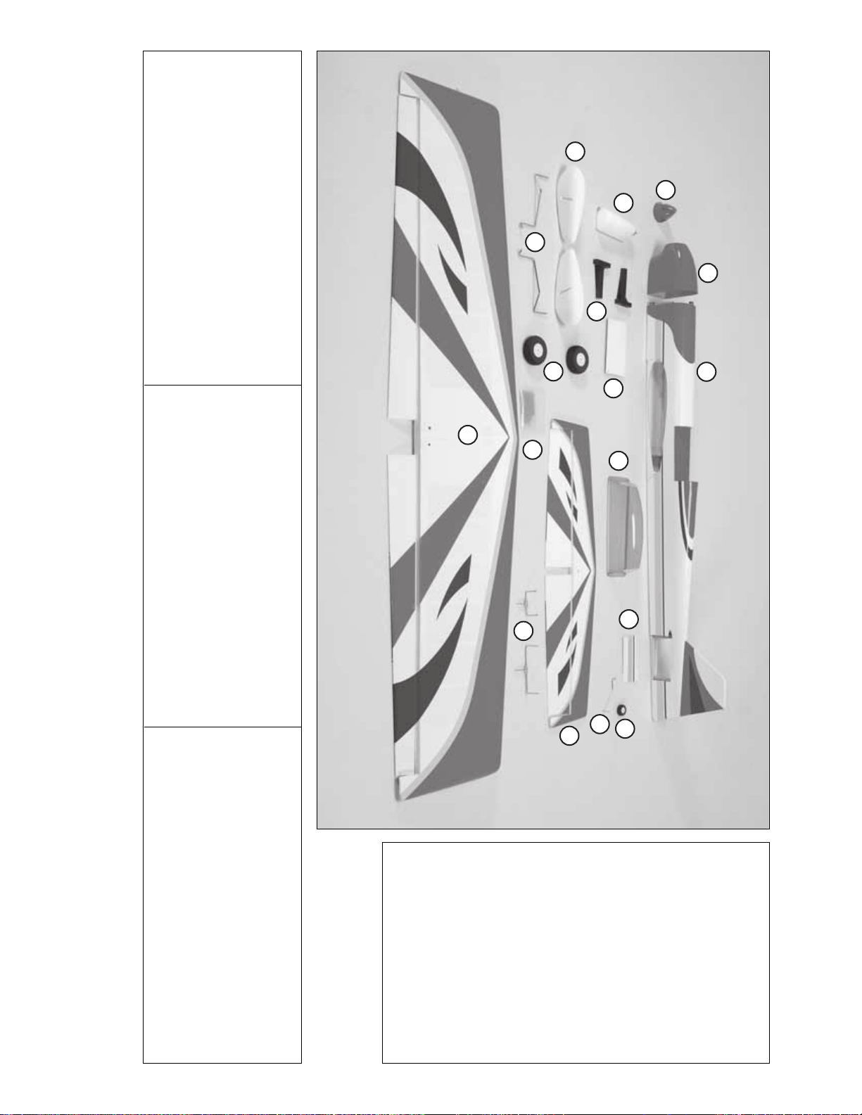
PARTS PHOTOGRAPHED
1. Fuselage
2. Cowl
3. Canopy
4. Fuel Tank Hatch Door
5. Hor izontal Stabilizer
w/Elevators
6. Wing w/Flaps
7. Spinner
8. Fuel Tank w/Hardware
9. Wheel Pants
10. Landing Gear
11. Elevator Control Horn
Access Hatch
12. Tail Wheel
13. Tailgear Wire
14. Elevator and Flap
Joiner Wires
15. Engine Mount Halves
16. Main Wheels
17. Steel Shot
PARTS NOT PHOTOGRAPHED
(1) Wing Tip Weight Hatch Access Door
(2) Nylon Tie Straps 395 mm
(14) 2 x 10 mm Self-Tapping Washer Head Screws
(23) 2 x 6 mm Self-Tapping Washer Head Screws
(5) 2 mm Nuts
(3) Silicone Clevis Retainers
(10) 3 mm Washers
(6) 3 x 25 mm Socket Head Machine Screws
(7) Nylon Landing Gear Straps
(3) 2 mm Steel Clevises
(4) 4 mm Blind Nuts
(6) 4 mm Washers
(2) 4 x 55 mm Machine Screws
(4) 4 x 20 mm Machine Screws
(4) 4 mm Lock Washers
(1) CA Hinge Strip
(1) 2 mm Wheel Collar
(4) 4 mm Wheel Collars
(5) 3 mm Set Screws
(1) 3 x 6 mm Machine Screw
(1) 305 mm Silicone Fuel Tubing
(4) 3 mm Nylon Locknuts
(2) Wing Dowels
(1) Aluminum Pushrod
(2) Pushrod Wires
(2) Landing Gear Retainer Plates
KIT CONTENTS
To convert inches to millimeters, multiply inches by 25.4
9
7
2
1
8
10
15
16
4
6
17
3
14
13
5
11
12
Page 5
- 5 -
ASSEMBLE THE WING
Install Flaps
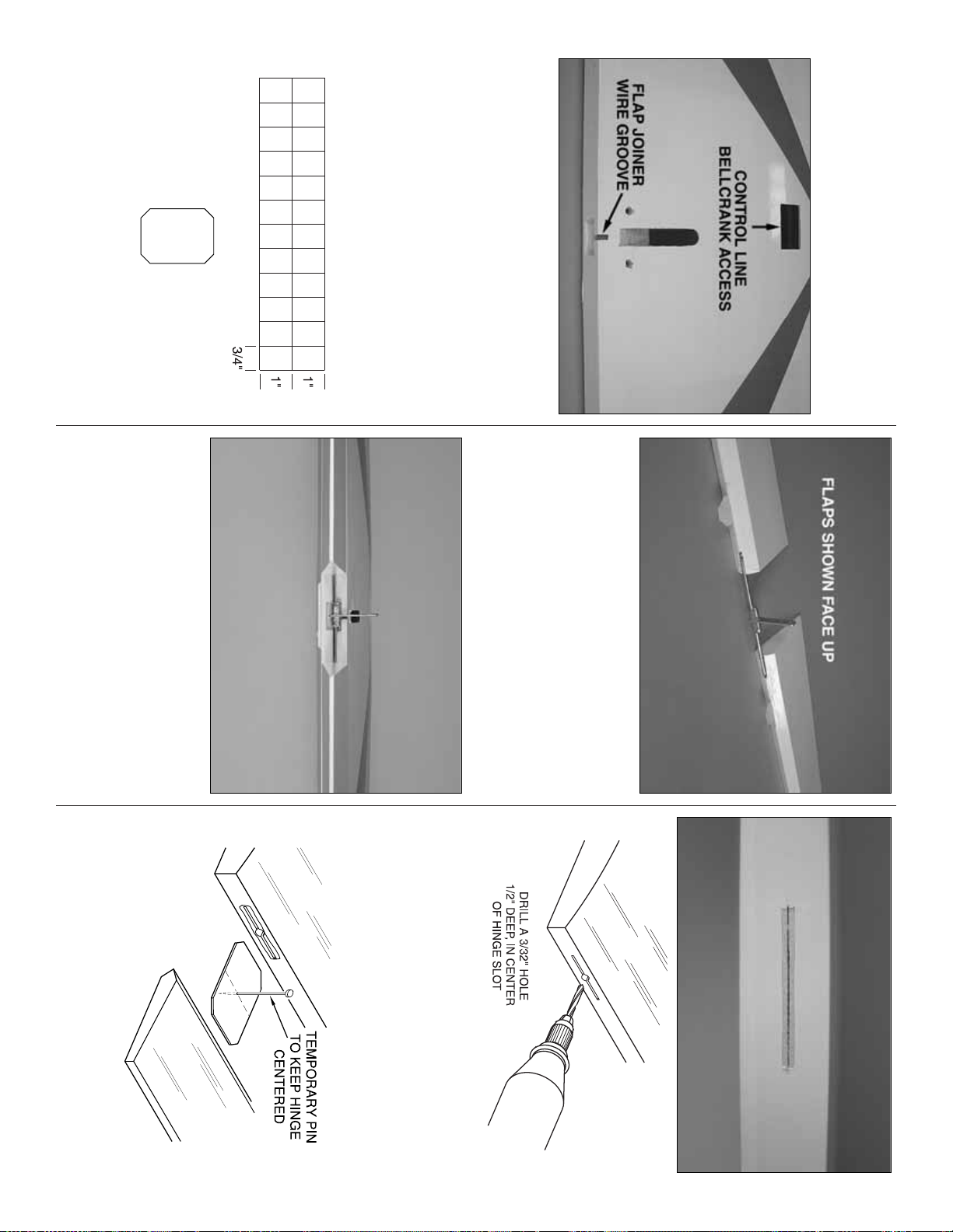
❏ 1. Carefully remove the tape holding the flaps to
the wing panels. Cut the covering from the control
line bellcrank access hole as well as the flap joiner
wire groove located in the center of the wing trailing
edge. If necessary, trim the covering from the two
wing bolt holes.
❏ 2. Cut the included 2" x 9" [51 x 229 mm] CA hinge
strip into 3/4" x 1" [19 x 25 mm] hinges as shown in
the drawing. Clip the corners of each hinge to allow
them to fit in the hinge slots easier.
❏ 3. Locate the holes and slots for the flap joiner
wire at the inside leading edge of both flaps and trim
the covering away. Temporarily install CA hinges
halfway into each of the pre-cut hinge slots in the
flaps.Test fit the flap joiner wire (the larger of the two
included joiner wires) into the joiner wire holes with
the control horn pointing up.
❏ 4. Temporarily attach the flaps to the wing by
sliding the CA hinges into their matching pre-cut
slots.View the trailing edges of the flaps from the end
of the wing. See if the flaps are parallel with each
other (have the same “up” and “down”).If necessary,
“tweak”, or bend the joiner to align the flaps.Be sure
to remove the joiner wire from the flaps before
attempting to bend it.
❏ 5. Remove the hinges and trim the covering from
the pre-cut CA hinge slots both on the wing and the
flaps. Drill a 3/32" [2.4 mm] hole into the center of
each hinge slot.
❏ 6. Insert the hinges into the slots in both flaps.Use
a T-pin to help keep the hinges centered in the slots
during assembly.
Page 6
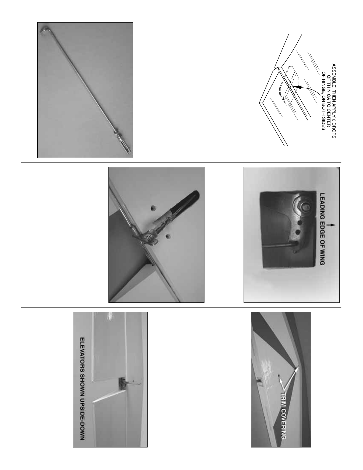
❏ 7. Roughen up the por tions of the joiner wire that
fit into the flaps with sandpaper. Clean the wire with
denatured alcohol. Mix a small batch approximately
7.5 cc [1/4 oz] of 30-minute epoxy. Use a piece of
wire or a toothpick to apply epoxy to the holes and
grooves in the flaps for the joiner wire. Coat the
matching halves of the joiner wire with epoxy, and
then insert it into the flaps. Join the flaps to the wing
by inserting the hinges into their mating slots in the
wing. Apply thin CA to the center of the hinges on
both sides. The hinges will secure the flaps in place
while the epoxy on the joiner wire cures.Wipe away
any excess epoxy with alcohol.
Install Flap Linkage
❏ 1.Thread a 2 mm nut, silicone clevis retainer, and
a metal clevis onto the flap pushrod wire.
❏ 2. Feed the bent end of the pushrod wire through
the cutout in the sheeting near the trailing edge of the
wing. Connect the pushrod to the outer hole on the
control line bellcrank.
❏ 3. With the bellcrank in the center position, adjust
the clevis until the flaps are neutral when the clevis is
connected to the middle hole on the flap joiner control
horn. Slide the silicone clevis retainer onto the clevis,
add threadlocking compound to the pushrod threads,
and tighten the 2 mm nut against the clevis to secure
it into place.
ASSEMBLE THE T AIL SECTION
Install Elevators
❏
1. Trim the covering from the two mounting holes
on the horizontal stabilizer and the elevator joiner
wire groove located in the center of the stab trailing
edge. As you did with the wing and flaps, trim the
covering from the pre-cut CA hinge slots both on the
stabilizer and the elevators.
❏ 2. Locate the holes and slots for the elevator joiner
wire at the inside leading edge of both elevators and
trim the covering away. Temporarily install CA hinges
halfway into each of the pre-cut hinge slots in the
elevators .Test fit the elevator joiner wire into the joiner
wire holes with the control horn pointing down.
❏ 3.T empor arily attach the ele vators to the stabilizer
by sliding the CA hinges into their matching pre-cut
slots.View the trailing edges of the elev ators from the
end of the stab. See if the elevators are parallel with
each other (have the same “up” and “down”). If
necessary, “tweak” the joiner to align them. Remove
the joiner wire from the elevators to do this.
- 6 -
Page 7

❏ 4. Roughen up the por tions of the joiner wire that
fit into the elevator with sandpaper. Clean the wire
with denatured alcohol. Mix a 7.5 cc [1/4 oz] batch of
30-minute epoxy. Use a piece of wire or a toothpick
to apply epoxy in the hole and groove in the elevator
for the joiner wire of only one elevator. Coat the
matching half of the joiner wire with epoxy, and then
insert it into the elevator.Secure the joiner wire to the
elevator while the epoxy cures.
❏ 5. After the epoxy has cured, reinsert the hinges
into that elevator and attach it to the stabilizer.
Position the elevator so that the elevator joiner
control horn is centered in the groove in the trailing
edge of the stab. Using the same procedure as the
flaps, permanently attach the elevator to the stab.
❏ 6.Maneuver the partially assembled stabilizer into
the fuselage. Using two 3 x 25 mm SHCS and two
3 mm washers, permanently mount the stab to the
fuselage. To prevent the screws from backing out,
use thread-locking compound.You can also glue the
stab into place with epoxy.
❏ 7. Just as you did with the wing, mix another small
batch of 30-minute epoxy and attach the other
elevator in the same manner. Before the epoxy cures,
secure the hinges with thin CA glue. The hinges will
hold the flap in place while the epoxy cures.
Install Elevator Linkage
❏ 1. Loosely install a 2 mm nut onto each end of the
remaining pushrods.Install a metal clevis with silicone
retainer onto one end of each remaining pushrod wire.
Thread the ends of the pushrod wires that only have a
nut installed on them into the ends of the aluminum
pushrod. Adjust the clevises and pushrod wires inside
the aluminum pushrod so that the total length of the
assembled pushrod is 18-3/4" [475 mm]. Be sure to
use threadlocking compound on the pushrod threads.
❏ 2. Slide the assembled pushrod through the
fuselage. Temporarily attach the clevis to the middle
hole in the elevator control horn.
❏ 3. Tighten the nut against the clevis at the other
end of the pushrod near the wing saddle. Be sure
that the clevis is threaded on about 6mm [1/4"].
❏ 4.Install the elevator control horn access hatches
using eight 2 x 6 mm self-tapping screws.
FINISH THE WING
Test Fit the Wing
❏ 1. Cut the covering from the holes in the front of the
wing and glue in the wing dowels with epoxy.Tap the
dowels into place as far as they will go into the holes.
❏ 2. Using two 4 x 55 mm screws and two 4 mm
washers, test fit the wing to the fuselage.
- 7 -
Page 8

Install the Belly Pan
❏ 1. Align the belly pan into position and tape it to
the fuselage.Use a felt tip pen to trace its shape onto
the wing.
❏ 2. Remove the belly pan and wing. Use a shar p,
new knife blade or a soldering iron (see “Hot Tip”) to
cut the covering from the wing 1/16" [2 mm] inside
the lines.If using a knife, use a light touch and great
care not to cut into the sheeting under the covering
or the wing will be weakened. After cutting the
covering, use denatured alcohol and a tissue to
clean the ink lines from the covering. Then, peel off
the covering.
HOW TO CUT COVERING FROM BALSA
Use a soldering iron to cut the covering from the stab.
The tip of the soldering iron doesn’t have to be sharp,
but a fine tip does work best.Allow the iron to heat fully .
Use a straightedge to guide the soldering iron at a
rate that will just melt the covering and not burn into
the wood. The hotter the soldering iron, the faster it
must travel to melt a fine cut.Peel off the covering.
❏ 3. Trim the covering from the underside edges of
the belly pan.Epoxy the belly pan to the wing and cut
away the covering from the wing bolt holes if you
have not already done so.Wick thin CA glue into the
wing bolt holes to harden the wood in this area.
Attach the Wing
❏ 1. Fit the two wing dowels into their mating holes
in the fuselage. While tilting the trailing edge of the
wing away from the fuselage, use needle nose pliers
to connect the elevator pushrod to the outer hole in
the flap control horn. Secure the clevis with the
silicone retainer.
❏ 2. Using the 4 x 55 mm screws and 4 mm washers,
secure the wing to the fuselage.
- 8 -
Page 9

- 9 -
LANDING GEAR
Assemble the Main Gear
❏❏
1. Slide the landing gear wire through the hole in
the wheel pant. Center a nylon strap over the wire
1/2" [13 mm] above the axle hole and drill 1/16" [1.6 mm]
holes through the strap and into the pant for the strap
screws.Temporarily secure the strap with two 2 x 10 mm
self-tapping screws. Back the screws out and apply a
few drops of thin CA to the screw holes. Be sure not to
block the holes with too much CA, and allow the glue to
dry completely before reinserting the screws.
❏❏2. Rough up the inside of the wheel pant with
sandpaper.Clean the area with alcohol and test fit the
retainer plate.Sand or trim the plate as necessary for
it to lay flat on the pant.Use epoxy to attach the plate
to the pant. Dab a bit of petroleum jelly to the end of
the landing gear wire and fit it into the retainer plate.
The jelly will prevent epoxy from sticking to the wire.
The landing gear wire will hold the plate in the correct
position while the epoxy cures.
❏❏3.Thread 3 mm set screws into two 4 mm wheel
collars. Install the wheel into the wheel pant by
securing a wheel collar to each side of it as shown in
the picture. File a small flat spot on the gear wire
where the set screws will be tightened. Be sure that
the wheel rotates smoothly on the landing gear wire.
Add oil to the gear wire if necessary.
❏ 4. Repeat these steps for the other wheel pant.
❏ 5.Test fit the landing gear wire into the wing. Make
any necessary adjustments like rounding over the
edge at the top of the hole for the gear wire to sit flat.
Center two nylon straps over the gear wire and mark
the holes for the straps.Drill 1/16" [1.6 mm] at those
marks. Use four 2 x 10 mm self-tapping screws to
install the gear. Reinforce the holes with thin CA as
done in previous steps.
Assemble the Tail Gear
❏ 1. Thread a 3 mm set screw into the 2 mm wheel
collar. Slide the tail wheel onto the tail wheel wire
followed by the wheel collar. Use thread-locking
compound to secure the set screw. Be sure the tail
wheel rotates freely when the set screw is tightened.
Oil the wheel if necessary.
FLAT SPOTS
Page 10

❏ 2. Locate the groove for the tail gear wire on the
underside of the fuselage and trim the covering awa y.
The hole at the front of the groove for the tail gear
wire is approximately 9-1/2" [241 mm] from the aft
end of the fuselage.Insert the tail wire into the groove
and secure it with a nylon strap and two 2 x 10 mm
self-tapping screws.
ENGINE AND FUEL SYSTEM
Mount the Engine
There are two engine mounting templates at the back
of this manual for the SuperTigre
®
.51 C/L engine and
the O.S. Max .40 LA-S engine. If you are not using
either of these engines, you will need to make y our own
mounting template based on the size of your engine.
❏ 1.Cut out the template from the back of this manual
that matches your engine. Align the dashed lines on
the template with the cross-hairs on the firewall and
tape the template in place. Use a T-pin or a small drill
bit to transfer the location of the f our mounting holes to
the firewall.
❏ 2.Remove the template and drill the mounting holes
with a 7/32" [5.6 mm] drill bit. Cut the sides from two
4mm blind nuts as shown.Install four 4 mm blind nuts
into the back of the holes.Draw the blind nuts tight into
the firewall by threading a 4 x 20 mm screw and 4 mm
washer through the engine mount and firewall into the
blind nuts and tightening the screw.
❏ 3. Install the engine mount halves inverted to the
firewall using four 4 x 20 mm screws, four 4 mm
washers, and four 4 mm lock washers.
❏ 4. Position the engine so that the drive washer is
4-1/8" [105 mm] from the firewall.Mark the positions of
the engine mounting holes onto the mounting rails (we
used a Great Planes Dead Center
™
Engine Mount
Hole Locator, GPMR8130) and drill the holes with a
1/8" [3.2 mm] drill bit.
- 10 -
Page 11

❏ 5. Secure the engine to the mount with four 3 mm
socket head cap screws, eight 3 mm washers and
four 3 mm nylon locknuts.
Assemble and Install the Fuel Tank
❏ 1. Install the three metal tubes into the black
stopper.The tubes should protrude about 1/2" [12 mm]
from the top of the stopper.Install the two metal plates
on the top and bottom of the stopper and secure them
loosely with the screw .Cut the fuel tubing for the clunk
to 3" [76 mm] and install it onto the shorter tube. The
other end of the fuel tubing receives the fuel pickup
clunk. Bend one long tube so that the inside end just
reaches the top of the tank when installed.This will be
the vent (pressure) line.The humped side of the tank
with the two grooves points do wnward when installed
into the fuselage.The other long tube remains straight.
This is the line for filling the tank.
❏ 2. Press the stopper into the fuel tank and secure it
by tightening the screw. Identify the three tubes with a
marking if necessary. Confirm that the clunk moves
around inside freely and reaches the back of the tank.
❏ 3. Use epoxy thinned with denatured alcohol,
epoxy or fuel proof paint to fuel proof the fuel
tank compartment.
❏ 4. Use 1/4" [6 mm] foam rubber (not included) to
line the top of the fuel tank where it will be held against
the fuel tank mounting plate inside the fuselage. Feed
the long tie straps through the rectangular cutouts on
the mounting plate. Position the tank inside the fuse
with the tank neck passing through the hole in the
firewall.When you are satisfied with the fit, draw the tie
straps tight. Cut away the ends of the tie straps.
❏ 5.Install the fuel tank hatch door with four 2 x 6 mm
self-tapping screws.Reinforce the holes with thin CA.
FINISHING THE MODEL
Install the Cowl
❏ 1. Use a high-speed rotary tool with a cutting bit to
cut an air inlet hole and an outlet in the cowl that is
large enough to accommodate the head of the
engine that you are using.
- 11 -
Page 12

❏ 2. Place a 6" [150 mm] long piece of masking tape
onto the fuselage over the three mounting blocks as
shown above. Draw a line 4" [102 mm] long starting
at the center of the cowl mounting blocks onto each
piece of tape.
❏ 3. Place the cowl on the fuselage and mount the
spinner backplate. There should be approximately
3/32" [2 mm] between the spinner and the cowl.Align
the cowl so that the spinner backplate is centered.
When satisfied with its position, use tape to hold the
cowl in place or ask a helper to hold it steady.
❏ 4. Using the lines you drew on the masking tape,
measure back 4" [100 mm] from the aft ends of the
lines and transfer the marks onto the cowl. These
marks will be the screw locations for the cowl
mounting screws. Drill 1/16" [1.6 mm] holes at the
three marks on the cowl into the cowl mounting blocks .
❏ 5. Remove the cowl and take off the masking tape.
Replace the cowl onto the fuselage and attach the
cowl with three 2 x 6 mm self-tapping screws and
reinforce the holes with thin CA glue.
❏ 6. Remove the cowl and insert the muffler screws
into the crankcase of the engine. Reinstall the cowl
and position the screws so they contact the inside of
the cowl and mark their location. Remove the cowl
again and cut holes at your marks. Insert the muffler
screws through the holes into the engine to confirm
that the holes are in the correct position.
❏ 7. Remove the cowl one more time. Line the
muffler against the muffler screw holes on the cowl
and trace its shape. Carefully cut out a hole for the
muffler.Trim the hole until you get a good fit.With the
cowl still removed, attach your fuel lines. Also,
consider where your needle valve is positioned. For
the engine shown in this manual, the remote needle
valve was mounted on its side and an access hole
was drilled in the cowl at that location.
- 12 -
Page 13

❏ 8. Reattach the cowl and secure the muffler to the
engine.Depending on the engine being used, you may
need to drill small access holes into the cowl to tighten
the muffler screws.For the engine shown, an allen key
was inserted through the hole for the needle valve and
the air intake. When filling the tank, fuel will overflow
through the vent line when full. A 3 x 6 mm screw is
included with the kit to be used as a fill line plug.
❏ 9. Reinstall the 2" [51 mm] spinner and propeller.
Install the Canopy
❏ 1. Trim the canopy along the molded cut lines.
❏ 2. Use masking tape to temporarily secure the
canopy to the fuselage.Drill four 1/16" [1.6 mm] holes,
evenly spaced, on the bottom sides of the canopy and
into the fuselage. Thread a 2 x 6 mm self-tapping
screw into each hole and back it out.Use thin CA glue
to harden the screw holes. Attach the canopy to the
fuselage using four 2 x 6 mm self-tapping screws.
Apply the Decals
1. Use scissors or a sharp hobby knife to cut the
decals from the sheet.
2. Be certain the model is clean and free from oily
fingerprints and dust. Prepare a dishpan or small
bucket with a mixture of liquid dish soap and warm
water–about one teaspoon of soap per gallon of water .
Submerse the decal in the soap and water and peel off
the paper backing.Note: Even though the decals have
a “sticky-back” and are not the water transfer type,
submersing them in soap and water allows accurate
positioning and reduces air bubbles underneath.
3. Position the decal on the model where desired.
Holding the decal down, use a paper towel to wipe
most of the water away.
4. Use a piece of soft balsa or something similar to
squeegee remaining water from under the decal.
Apply the rest of the decals the same way.
GET THE MODEL READY TO FLY
Balance the Model (C.G.)
At this stage the model should be in ready-to-fly
condition with all of the systems in place including
the engine, landing gear, and all hardware.
More than any other factor, the C.G. (balance
point) can have the greatesteffect on how a model
flies, and may determine whether or not your first
flight will be successful.If you value this model and
wish to enjoy it for many flights, DO NOT
OVERLOOK THIS IMPORTANT PROCEDURE. A
model that is not properly balanced will be
unstable and possibly unflyable.
- 13 -
Page 14

- 14 -
❏ 1. Use a felt-tip pen or 1/8" [3 mm]-wide tape to
accurately mark the C.G.on the bottom of the wing on
both sides of the fuselage.The C.G. is located 4-1/8"
[105 mm] back from the leading edge of the wing.
❏ 2.With the wing attached to the fuselage, all parts
of the model installed (ready to fly) and an empty fuel
tank, place the model on a Great Planes CG
Machine
™
, or lift it at the balance point you marked.
❏ 3. If the tail drops, the model is “tail heavy”, and
weight must be added to the nose to balance. If the
nose drops, the model is “nose heavy”;weight must be
added to the tail to balance. If additional weight is
required, nose weight may be easily added by using a
“spinner weight”(GPMQ4645 for the 1 oz [28 g] weight,
or GPMQ4646 for the 2 oz [57 g] weight). If spinner
weight is not practical or is not enough, use Great
Planes (GPMQ4485) “stick on” lead. A good place to
add stick-on nose weight is to the firewall (don’t attach
weight to the cowl–it is not intended to support weight).
Begin by placing incrementally increasing amounts of
weight on the bottom of the fuse over the firewall until
the model balances. Once you have determined the
amount of weight required, it can be permanently
attached. If required, tail weight may be added by
securing it to the inside of the hatch doors.
Note: Do not rely upon the adhesive on the back of
the lead weight to permanently hold it in place. Over
time, fuel and exhaust residue may soften the
adhesive and cause the weight to fall off. Use #2
sheet metal screws, RTV silicone or epoxy to
permanently hold the weight in place.
❏ 4. IMPORTANT: If you found it necessary to add
any weight, recheck the C.G. after the weight has
been installed.
Wing Tip Weight
The Score Control Line ARF includes 1-3/4 oz [53 g] of
steel shot. We suggest starting out by using 1 oz of
stick-on lead weight applied to the underside of the wing
at the tip near the tip weight hatch door.Add or subtract
weight after test flying the model to determine the final
amount needed based on flying preference. You can
then permanently add tip weight to the model by mixing
the appropriate amount of steel shot with epoxy and
pouring it into the tip weight compartment. When the
epoxy has cured, screw the tip weight hatch door to the
wing using four 2 x 6 mm screws or glue it into place.
PREFLIGHT
Balance Propellers
Carefully balance your propeller and spare propellers
before you fly. An unbalanced prop can be the single
most significant cause of vibration that can damage
your model. Not only will engine mounting screws and
bolts loosen, possibly with disastrous effect, but
vibration can also cause your fuel to foam, which will, in
turn, cause your engine to run hot or quit.We use a Top
Flite Precision Magnetic Prop Balancer (TOPQ5700) in
the workshop and keep a Great Planes Fingertip Prop
Balancer (GPMQ5000) in our flight box.
Engine Check
If the engine is new , follow the engine manufacturer’s
instructions to break-in the engine. After break-in,
confirm that the engine idles reliably, and maintains
full power–indefinitely. After you run the engine on
the model, inspect the model closely to make sure all
screws remained tight, the hinges are secure, the
prop is secure and all connectors are secure.
Control Check
With the lines connected to the leadouts and your
assistant holding the model, operate the controls to
make sure they move smoothly. If any binding or
hesitation is detected, inspect the model and
eliminate the problem.
This is where your model should balance for the first
flights.Later, you may wish to experiment b y shifting
the C.G.up to 3/8" [9.5 mm] forward or 3/8" [9.5 mm]
back to change the flying characteristics.Moving the
C.G. forward may improve the smoothness and
stability , but the model ma y then require more speed
for takeoff and make it more difficult to slow for
landing. Moving the C.G.aft makes the model more
maneuverable, but could also cause it to become
too difficult to control. In any case, start at the
recommended balance point and do not at any
time balance the model outside the specified range.
Page 15

Adjust Leadouts
This model is equipped with adjustable leadouts.The
lines can be adjusted by means of a Phillips head set
screw located inside the slot provided for the leadouts .
The leadouts can be loosened, then slid fore and aft.
When they are in place, tighten the set screw down to
prevent the leadouts from moving back and forth in
flight. You should also check the leadouts after each
flight, making sure the screw is tight.
As a general guideline, positioning the leadouts
further aft makes the plane pull harder on the lines
(for windy days), b ut also mak es the plane “handle”or
react a little slower.This positioning is recommended
for less-powerful engines or longer lines and is also a
good way to counter the effect of having not enough
wing tip weight.
Further forward makes the plane pull less hard on
the lines, thus quickening response. This can be
better for calm days, and better for faster, more
powerful engines or shorter lines. It is also a way to
counter the effect of having too much wing tip w eight.
The exact placement of these leadouts will be a matter
of experimentation to match your flying style;however ,
we recommend centering the two leadouts in their
slots as a starting point.
ENGINE SAFETY PRECAUTIONS
• Keep all engine fuel in a safe place, awa y from high
heat, sparks or flames, as fuel is very flammable.
Do not smoke near the engine or fuel; and
remember that engine exhaust gives off a great
deal of deadly carbon monoxide.Therefore do not
run the engine in a closed room or garage.
• Get help from an experienced pilot when learning
to operate engines.
• Use safety glasses when starting or running engines.
• Do not run the engine in an area of loose gravel or
sand; the propeller may throw such material in
your face or eyes.
• Keep your face and body as well as all spectators
away from the plane of rotation of the propeller as
you start and run the engine.
• Keep these items away from the prop: loose
clothing, shirt sleeves, ties, scarfs, long hair or
loose objects such as pencils or screwdrivers that
may fall out of shirt or jacket pockets into the prop.
• Use a “chicken stick” or electric star ter to start the
engine. Do not use your fingers to flip the
propeller. Make certain the glow plug clip or
connector is secure so that it will not pop off or
otherwise get into the running propeller.
• Make all engine adjustments from behind the
rotating propeller.
• The engine gets hot! Do not touch it during or right
after operation. Make sure fuel lines are in good
condition so fuel will not leak onto a hot engine,
causing a fire.
• To stop a glow engine, cut off the fuel supply by
closing off the fuel line or following the engine
manufacturer’s recommendations. Do not use
hands, fingers or any other body part to try to stop
the engine. Do not throw anything into the propeller
of a running engine.
AMA SAFETY CODE (EXCERPTS)
Read and abide by the following excer pts from the
Academy of Model Aeronautics Safety Code.For the
complete Safety Code refer to
Model Aviation
magazine, the AMA web site or the Code that came
with your AMA license.
General
1. I will not fly my model aircraft in sanctioned events,
air shows, or model flying demonstrations until it
has been proven to be airworthy by having been
previously, successfully flight tested.
3.Where established, I will abide by the safety rules
for the flying site I use, and I will not willfully and
deliberately fly my models in a careless, reckless
and/or dangerous manner.
5. I will not fly my model unless it is identified with my
name and address or AMA number, on or in the
model. Note: This does not apply to models while
being flown indoors.
7. I will not operate models with pyrotechnics (any
device that explodes , burns, or propels a projectile
of any kind).
Failure to follow these safety precautions may
result in severe injury to yourself and others.
- 15 -
Page 16

8. I will not consume alcoholic beverages prior to, nor
during, participation in any model operations.
9. Children under 6 years old are only allowed on the
flight line as a pilot or while under flight instruction.
Control Line
1. I will subject my complete control system (including
safety thong, where applicable) to an inspection and
pull test prior to flying. Pull test will be in accordance
with the current Competition Regulations for
applicable model category. Models not fitting a
specific category as detailed shall use those pull test
requirements for Control Line Precision Aerobatics.
2. I will assure that my flying area is safely clear of all
utility wires or poles.
3. I will assure that my flying area is safely clear of all
non-essential participants and spectators before
permitting my engine to be started.
4. I will not fly a model closer than 50 feet [15m] to
any electrical power line.
CHECK LIST
❏ 1. Fuelproof all areas exposed to fuel or exhaust
residue such as the fuel tank compartment.
❏ 2. Check the C.G.according to the measurements
provided in the manual.
❏ 3. Use threadlocking compound to secure
critical components.
❏ 4. Add a drop of oil to the axles so the wheels will
turn freely.
❏ 5. Make sure all hinges are securely glued in place .
❏ 6. Reinforce holes for wood screws with thin CA
where appropriate.
❏ 7. Confirm that the flaps and elevators operate
freely and smoothly by pulling on the leadouts.
❏ 8. Make sure there are silicone retainers on all
the clevises.
❏ 9. Secure the pressure tap (if used) to the muffler
with high temp RTV silicone, thread locking
compound or J.B.Weld.
❏ 10. Make sure the fuel lines are connected and
are not kinked.
❏ 11.Balance your propeller (and spare propellers).
❏ 12.Tighten the propeller nut and spinner.
❏ 13.If you wish to photograph your model, do so
before your first flight.
FLYING
Flying Precautions
Preflight
Note: The Top Flite Score ARF is not a beginner’s
model. It is intended for beginning to advanced stunt
pilots who have had some previous control line
experience. If you are an inexperienced pilot seek
the assistance of a knowledgeable control line pilot
who can help you with your first flights.
Beginning stunt pilots should make their first flights in
calm or low wind conditions. Stronger winds may
blow the model inward which will decrease line
tension resulting in loss of control.If the lines ever do
go slack, quickly step back to tighten the lines and
regain control. Of course, this is most likely to
happen, and should be expected, as the model
approaches the upwind half of the circle.
Study these flying safety precautions before
flying the Score ARF.
1. Always inspect your equipment before each
flight. Make certain the lines, leadouts and
handle are in good condition.Make sure there
are no kinks in the lines.
2. Fly only in unobstructed areas free from trees,
shrubs and bushes, poles, stakes, parking
barriers and fences.
3. Be aware of any spectators that may wander
into the flying circle. If this is a possibility,
have
your assistant ready to perform crowd control.
4. The model must NEVER be flown in the
vicinity of high-tension lines or any other
electrical lines.
5. Never fly when thunder storms or lightning
are present.
6. Take any precautions necessary to insure the
safety of spectators, the model and property.
7. Never touch the engine during or soon
after operation.
8. Keep clear of the rotating propeller and do
not let assistants or spectators get in the arc
of the propeller.
During the last few moments of preparation your
mind may be elsewhere anticipating the
excitement of the first flight. Because of this, you
may be more likely to overlook certain checks and
procedures that should be performed before the
model is flown. To help avoid this, a check list is
provided to make sure these important areas are
not overlooked. Many are covered in the
instruction manual, so where appropriate, refer to
the manual for complete instructions. Be sure to
check the items off as they are completed.
- 16 -
Page 17

Place the model and starting equipment where the wind
will be behind the model when it is released for takeoff.
For the first half-circle (during the brief period when
the pilot has the least control before the model is “up
to speed”) the wind will push the model outward to
maintain line tension.
Mark the center of the flying circle with paint, chalk or
a suitable object (such as a shop towel) so you won’t
wander.This is especially important if the flying area
is limited.
With your assistant holding the model, walk from the
model toward the handle in the center of the circle
while using your fingers to keep the lines separated.
This will ensure that the lines are not twisted and are
free to operate the controls.
While the pilot is holding the lines, the assistant
should walk the model once around the circle to be
certain the flight path is clear and to double-check
that
there are no obstructions that could snag the lines.
The pilot should double-check the operation of the
controls by pulling and pushing on the handle and
having the assistant signal what the controls are
doing (“up” and “down”).
Takeoff
Note: A fully cowled engine may run at a higher
temperature than an un-cowled engine. Therefore,
the fuel mixture should be richened so the engine
runs at least 200 RPM below peak speed.By running
the engine slightly rich, you will help prevent dead-
stick landings caused by overheating. Traditionally,
control line pilots intentionally set their engines rich
so that during vertical maneuvers, the engine will not
“over lean,” thus causing overheating. Further, full
RPM is usually not desired for stunt flying.
When both the pilot and assistant are ready, the
model may be fueled and started.Once the engine is
running and the model is ready to be released, the
assistant should point the nose of the model slightly
away from the circle .This will help keep the lines taut
for the first few feet until the model gets going.
Upon the pilot’s signal, the assistant may release the
model–never push the model forward as doing so
may result in a crash.
The pilot should be ready–especially during
takeoff–to briefly step back to maintain line tension
until the model has gained enough air speed to
achieve line tension on its own. Allow the model to
roll out and gain enough speed to become airborne.
When enough speed has been gained the pilot may
raise his arm slightly giving “up” elevator command,
thus allowing the model to leave the ground.
Once the model has lifted, maintain a slow and steady
climb until a comfortable altitude has been
reached
(usually between “ey e-lev el”and
approximately ten feet
in the air). The lines must remain taut throughout the
entire flight. If the lines ever do go slack the pilot will
not have control of the model. During most situations
the model’s factory built-in features will allow it to
maintain good line tension, but on occasions when the
wind blows the model inward or the model becomes
too slow the modeler must anticipate or notice a
decrease in “pull”and quickly step backward to tighten
the lines and regain control.
- 17 -
Page 18

To climb, the pilot will slowly raise his arm. To
descend, the pilot will slowly lower his arm. To
maintain level flight the pilot will hold his arm
horizontally .Beginning pilots should control the model
by keeping their arm straight and bending at the
elbow with little or no wrist movement. Later, when
they become more experienced, wrist movement ma y
be increased to increase control response.All control
inputs should be smooth.Continue flying the model in
a level attitude , getting used to ho w the controls react
and how the model “feels.” Do this until the engine
runs out of fuel. Actual flight time depends on several
factors, such as the engine size and brand, needle
valve setting, propeller size, fuel, atmospheric
conditions, etc.
Landing
When the engine starts to sputter and/or speed up, this
is an indication that the tank is nearly empty .Continue to
fly the model in a level attitude until the engine finally
quits.The same as any time the model slows, the pilot
should step back to keep the lines taut and maintain
control. Allow the model to descend until it is about two
feet off the ground.When the model has lost nearly all
flying speed and is a foot or two from the ground the pilot
should raise his arm to keep the lines taut and apply full
up elevator, allowing the model to gently touch down.
After the model has come to a stop the assistant may
retrieve the model and return it to the starting area.
In doing so the lines should be kept taut so they do
not become twisted or entangled.
Clean the model using paper towels and household
cleaner to wipe off exhaust residue. Inspect the
model thoroughly, looking for loose fasteners and
signs of damage or fatigue.Also make sure the prop
has not been damaged. Perform any maintenance
necessary to prepare the model for the next flight.
At the end of the flying session any residual fuel
should be drained from the tank.
After you have become familiar with the way your
Score flies and you are ready to begin performing
stunts, seek the assistance of an experienced stunt
pilot before attempting to learn new maneuvers on
your own. Almost any control line stunt maneuvers
are started with the model downwind from the pilot,
i.e.wind on the pilot’s bac k.Consult the AMA Control
Line section for stunt maneuvers.
One final note about flying your model.Have a goal or
flight plan in mind for every flight.This can be learning
a new maneuver(s), improving a maneuver(s) you
already know, or learning how the model behaves in
certain conditions (such as when testing different
propellers or fuel). This is not necessar ily to improve
your skills
(though it is never a bad idea!)
, but more
importantly so you do not surprise yourself by
impulsively attempting a maneuver and suddenly
finding that you’ve run out of time, altitude or airspeed.
Every maneuver should be deliberate, not impulsive.
For example, if you’re going to do a loop, check your
altitude and mind the wind direction. A flight plan
greatly reduces the chances of crashing your model
just because of poor planning and impulsive moves.
Remember to think!
Have a ball, keep the lines taut
and always fly in a safe manner.
GOOD LUCK, GREAT FLYING, AND HAVE FUN!
- 18 -
Page 19

Consecutive Outside Square Loops
Consecutive Inside Loops
- 19 -
Takeoff
Consecutive Inside Square Loops
Consecutive Inside
Triangular Loops
AMA STUNT MANEUVERS
Here are some of the AMA Stunt Maneuvers.Refer to the AMA Rule Book for full descriptions.
Consecutive Outside Loops
Horizontal Eights
Inverted Flight
Reverse Wingovers
Engine Mounting
Template for
SuperTigre .51 C/L
Engine Mounting
Template for
O.S. .40 LA-S
Page 20

 Loading...