

Page 1
WARRANTY.....Top Flite
®
Models guarantees this kit to be free from defects in both material and workmanship at the date of purchase.This warranty
does not cover any component parts damaged by use or modification.In no case shall Top Flite’s liability exceed the original cost of the purchased kit. Further, Top Flite
reserves the right to change or modify this warranty without notice. In that Top Flite has no control over the final assembly or material used for final assembly, no liability shall
be assumed nor accepted for any damage resulting from the use by the user of the final user-assembled product. By the act of using the user-assembled product, the user
accepts all resulting liability .If the buyer is not prepared to accept the liability associated with the use of this pr oduct,the buyer is advised to return this kit immediately
in new and unused condition to the place of purchase.
Top Flite Models Champaign, IL Telephone (217) 398-8970, Ext. 5 airsupport@top-flite.com
READ THROUGH THIS INSTRUCTION BOOK FIRST. IT CONTAINS IMPORTANT INSTRUCTIONS AND WARNINGS CONCERNING THE ASSEMBLY AND USE OF THIS MODEL.
TOPZ0010 for TOPA1010 V1.0
Entire Contents © Copyright 2005
Wingspan: 54 in [1,370mm]
Wing Loading: 13 oz/sq ft [39 g/dm
2
]
Length: 43 in [980mm]
Wing Area: 594 sq in [38.3 dm
2
]
Prop: 11x4 Top Flite Power Point Prop
Weight: 3.5 – 4 lb [1,590 – 1,815g]
Engine: .40 – .46 cu in [5.5 – 7.5cc]
2-stroke glow control line
™
Page 2
TABLE OF CONTENTS
INTRODUCTION . . . . . . . . . . . . . . . . . . . . . . . . 2
IMPORTANT SAFETY PRECAUTIONS . . . . . . . 2
ENGINE & LINE RECOMMENDATIONS . . . . . . 3
ADDITIONAL ITEMS REQUIRED. . . . . . . . . . . . 3
Hardware & Accessories. . . . . . . . . . . . . . . 3
Adhesives & Building Supplies . . . . . . . . . . 3
Optional Supplies & Tools . . . . . . . . . . . . . . 3
Covering Tools . . . . . . . . . . . . . . . . . . . . . . 3
KIT INSPECTION. . . . . . . . . . . . . . . . . . . . . . . . 4
ORDERING REPLACEMENT PARTS . . . . . . . . . 4
IMPORTANT BUILDING NOTES . . . . . . . . . . . . 4
KIT CONTENTS. . . . . . . . . . . . . . . . . . . . . . . . . 5
BUILDING INSTRUCTIONS. . . . . . . . . . . . . . . . 6
Assemble the Main Wing. . . . . . . . . . . . . . . 6
Install the Horizontal Stab . . . . . . . . . . . . . . 7
Attach the Elevators . . . . . . . . . . . . . . . . . . 8
Attach the Fin . . . . . . . . . . . . . . . . . . . . . . . 8
Install the Flaps. . . . . . . . . . . . . . . . . . . . . . 9
Connect the Flap Pushrod. . . . . . . . . . . . . . 9
Connect the Elevator Pushrod . . . . . . . . . . 10
LANDING GEAR INSTALLATION . . . . . . . . . . 11
Install the Main Gear. . . . . . . . . . . . . . . . . 11
Install the Tail Gear . . . . . . . . . . . . . . . . . . 12
ENGINE INSTALLATION . . . . . . . . . . . . . . . . . 12
FUEL T ANK INSTALLATION . . . . . . . . . . . . . . 13
Assemble the Fuel Tank . . . . . . . . . . . . . . 13
Mount the Fuel Tank . . . . . . . . . . . . . . . . . 13
FINAL DETAILS. . . . . . . . . . . . . . . . . . . . . . . . 14
Control Surface Check . . . . . . . . . . . . . . . 14
Mount the Canopy. . . . . . . . . . . . . . . . . . . 14
Apply the Decals. . . . . . . . . . . . . . . . . . . . 14
GET THE MODEL READY TO FLY . . . . . . . . . . 15
Balance the Model (C.G.) . . . . . . . . . . . . . 15
Balance the Propeller . . . . . . . . . . . . . . . . 15
Engine Check . . . . . . . . . . . . . . . . . . . . . . 15
Control Check. . . . . . . . . . . . . . . . . . . . . . 15
Adjustable Leadouts . . . . . . . . . . . . . . . . . 15
ENGINE SAFETY PRECAUTIONS . . . . . . . . . . 16
AMA SAFETY CODE (excerpt) . . . . . . . . . . . . 16
General. . . . . . . . . . . . . . . . . . . . . . . . . . . 16
Control Line . . . . . . . . . . . . . . . . . . . . . . . 16
CHECK LIST . . . . . . . . . . . . . . . . . . . . . . . . . . 17
FLYING . . . . . . . . . . . . . . . . . . . . . . . . . . . . . . 17
Preflight . . . . . . . . . . . . . . . . . . . . . . . . . . 17
Takeoff . . . . . . . . . . . . . . . . . . . . . . . . . . . 18
Landing. . . . . . . . . . . . . . . . . . . . . . . . . . . 18
AMA STUNT MANEUVERS . . . . . . . . . . . . . . . 19
INTRODUCTION
Congratulations and thank you for purchasing the
Top Flite Control Line Tutor II ARF. Reincarnated
and enlarged from original Top Flite plans, the Tutor
II ARF is a perfect way to get into beginner stunt
flying without the initial time and money commitment
required for today’s kit-built stunters.And if you plan
to just dabble in control line, the Tutor II ARF has the
perfect blend of maneuverability and stability to get
you into the air with minimal assistance from an
experienced flyer.
1.Your Top Flite Tutor II ARF should not be considered
a toy, but rather a working model that functions like a
full-size airplane. Because of its performance
capabilities, the Tutor II ARF, if not assembled and
operated correctly, could possibly cause injury to
yourself or spectators and damage to property.
2. You must assemble the model according to the
instructions. Do not alter or modify the model, as doing
so may result in an unsafe or unflyable model. In a few
cases the instructions may differ slightly from the
photos. In those instances the written instructions
should be considered as correct.
3.You must take time to build straight, true and strong.
4. You must use control lines that are in first-class
condition with appropriate length and diameter. Use a
correctly sized engine and components throughout the
building process.
5. You must correctly install all pushrods and other
components so that the model operates correctly on the
ground and in the air.
6. You must check the operation of the model before
every flight to insure that all equipment is operating and
that the model has remained structurally sound.
7. If you are not already an experienced control line
pilot, you should fly the model only with the help of a
competent, experienced control line pilot.
8.While this kit has been flight tested to exceed normal
use, if the plane will be used for extremely high stress
flying, such as racing, the modeler is responsible for
taking steps to reinforce the high stress points.
Remember: Take your time and follow the
instructions to end up with a well-built model that is
straight and true.
If you have not flown a control line stunt model before,
we recommend that you get the assistance of an
experienced pilot in your club for your first flights. If
you’re not a member of a club, your local hobby shop
has information about clubs in your area whose
membership includes experienced pilots.
Note: We , as the kit manufacturer, provide you with
a top quality, thoroughly tested kit and instructions,
but ultimately the quality and flyability of your
finished model depends on how you build it;
therefore, we cannot in any way guarantee the
performance of your completed model, and no
representations are expressed or implied as to the
performance or safety of your completed model.
PRO TECT YOUR MODEL,
YOURSELF & OTHERS
FOLLO W THESE IMPORT ANT
SAFETY PRECAUTIONS
- 2 -
Page 3

In addition to joining a control line club, we strongly
recommend you join the AMA (Academy of Model
Aeronautics). AMA membership is required to fly at
AMA sanctioned clubs.Among other benefits, the AMA
provides insurance to its members who fly at
sanctioned sites and events. Additionally, training
programs and instructors are available at AMA club
sites to help you get started the right way. Contact the
AMA at the following address or toll-free phone number:
Academy of Model Aeronautics
5151 East Memorial Drive
Muncie, IN 47302-9252
Tele. (800) 435-9262
Fax (765) 741-0057
Or via the Internet at: http://www .modelaircraft.org
ENGINE & LINE
RECOMMENDATIONS
ADDITIONAL ITEMS REQUIRED
Hardware & Accessories
Following is a list of hardware and accessories
required to finish the Top Flite Control Line Tutor II
ARF. Order numbers are provided in parentheses.
❏ 3' [900mm] Std silicone fuel tubing (GPMQ4131)
❏ Control lines, .018" x 70' (SULP2636)
❏ 1/4" [6mm] White striping tape (GPMQ1610)
❏ Line connectors, Large, 50lb test (SULP2949)
❏ Standard INSTA JUST handle (SULP2866)
Adhesives & Building Supplies
In addition to common hobby tools and household
tools, this is the “short list” of the most important items
required to build the Top Flite Tutor II ARF. Great
Planes
®
Pro
™
CA and Epoxy glue are recommended.
❏ Great Planes 1/2 oz. Thin Pro CA (GPMR6001)
❏ Great Planes Pro 30-minute epoxy (GPMR6047)
❏ Great Planes Threadlocker
™
thread-locking
cement (GPMR6060)
❏ Hobbico
®
#1 Hobby knife (HCAR0105)
❏ Hobbico #11 Blades (5-pack HCAR0211, or 100-
pack HCAR0311)
❏ Drill bits: 1/16" [1.6mm], 5/64" [2mm], 3/32"
[2.4mm], 1/8" [3.2mm], 9/64" [3.6mm]
❏ Small metal file
❏ Great Planes Stick-on segmented lead
weights (GPMQ4485)
❏ Hobbico Medium T-pins (100, HCAR5150)
❏ Sandpaper assortment
Optional Supplies & Tools
These are some of the items used while building the
Tutor II ARF that are not absolutely necessar y, but
are mentioned in the manual.
❏ Top Flite Panel line pen (TOPQ2510)
❏ Hobbico CA applicator tips (HCAR3780)
❏ Great Planes CA debonder (GPMR6039)
❏ Great Planes Pro 6-minute epoxy (GPMR6045)
❏ Great Planes Epoxy brushes (6, GPMR8060)
❏ Great Planes Mixing sticks (50, GPMR8055)
❏ Great Planes Mixing cups (GPMR8056)
❏ Hobbico Builder’s Triangle Set (HCAR0480)
❏ Hobbico Curved-tip canopy scissors for trimming
plastic parts (HCAR0667)
❏ Denatured alcohol (for epoxy clean up)
❏ Bulk Kevlar cable 30' [9m] (SULQ3223)
❏ Great Planes CG Machine
™
(GPMR2400)
❏ Top Flite Precision Magnetic Prop Balancer
™
(TOPQ5700)
❏ Rotary Tool such as Dremel
®
❏ Great Planes Double-sided Servo Tape 1" x 3'
[25x915mm] (GPMQ4442)
Covering T ools
❏ 21st Century
®
(COVR2700) or Top Flite MonoKote
®
sealing iron (TOPR2100)
❏ 21st Century (COVR2702) or Top Flite Hot Sock
™
iron cover (TOPR2175)
A .40-.46 [5.5-7.5cc] sized control line engine is
required for this plane to achieve its potential.
Crisp maneuvers will not be possible with an
underpowered engine. Stepping above the
recommended engine range may negatively
influence the flight characteristics and stability of
the Tutor II.Therefore, for maxim um enjoyment w e
recommend staying in the engine range specified.
Also, due to the speed and size of this plane, we
recommend flying on 65-70ft [20-22m] lines.
Shorter lines will increase the speed at which the
pilot turns and maneuvers will have to be
executed much more quickly.
- 3 -
Page 4
KIT INSPECTION
Before starting to build, take an inv entory of this kit to
make sure it is complete, and inspect the parts to
make sure they are of acceptable quality. If any parts
are missing or are not of acceptable quality, or if you
need assistance with assembly, contact Product
Support. When reporting defective or missing parts,
use the part names exactly as they are written in the
Kit Contents list on page 5.
Great Planes Product Support
3002 N Apollo Drive Suite 1
Champaign, IL 61822
Telephone: (217) 398-8970
Fax:(217) 398-7721
E-mail:
airsupport@top-flite.com
ORDERING REPLACEMENT PARTS
Replacement parts are not available from Product
Support, but can be purchased from hobby shops or
mail order/Internet order firms. Hardware items
(screws, nuts, bolts) are also available from these
outlets. If you need assistance locating a dealer to
purchase parts, visit www.greatplanes.com and
click on “Where to Buy.” If this kit is missing parts,
contact Product Support.
IMPORTANT BUILDING NOTES
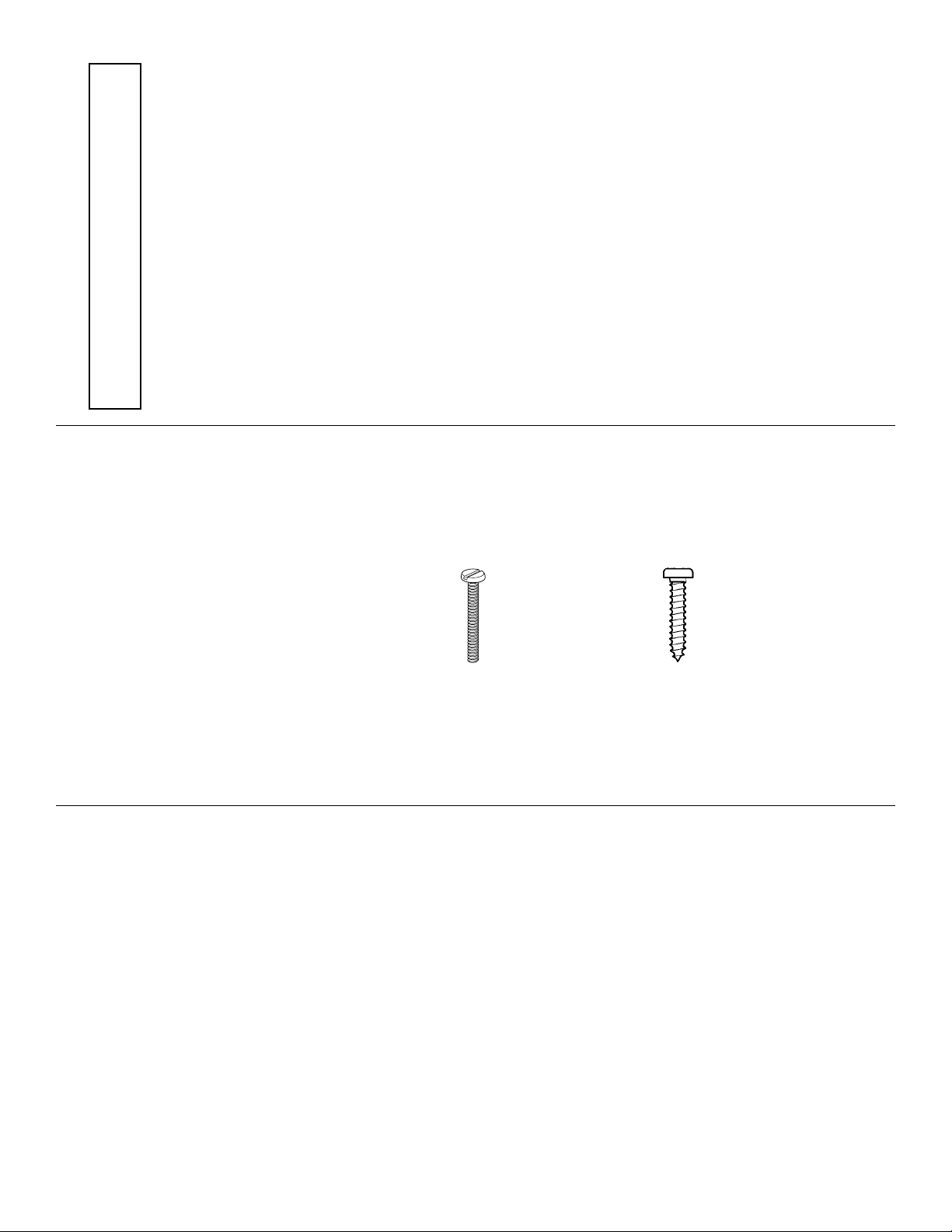
• There are two types of screws used in this kit:
Sheet metal screws are designated by a number
and a length.
For example #6 x 3/4" long [19mm]
This is a number six screw that is 3/4" [19mm] long.
Machine screws are designated by a number,
threads per inch, and a length.
For example 4-40 x 3/4" long [19mm]
This is a number four screw that is 3/4" [19.1mm]
long with forty threads per inch
.
• When you see the ter m
test fit
in the instructions, it
means that you should first position the part on the
assembly without using an y glue, then slightly modify
or
custom fit
the part as necessar y for the best fit.
• Whenever the term
glue
is written you should rely
upon your experience to decide what type of glue
to use.When a specific type of adhesive works best
for that step, the instructions will tell you what glue
is recommended.
• Whenever just
epoxy
is specified, you may use
either
30-minute (or 45-minute) epoxy
or
(or optional)
6-minute epoxy. When 30-minute epoxy is specified,
it is highly recommended that you use only 30-
minute (or 45-minute) epoxy because you will need
the working time and/or the additional strength.
• Photos and sketches are placed before the
step they refer to. Frequently you can study photos in
following steps to get another view of the same parts.
Note: The stabilizer and wing incidences and engine
thrust angles have been factory-built into this
model. However, some technically-minded modelers
may wish to check these measurements anyway.
To view this information, visit the web site at
www.top-flite.com
and click on “Technical Data.”
Due to manufacturing tolerances which will hav e little
or no effect on the way the model will fly, there may
be slight deviations between your model and the
published values.
Note: Full-size plans are not available for the
Tutor II ARF.
- 4 -
Page 5
- 5 -
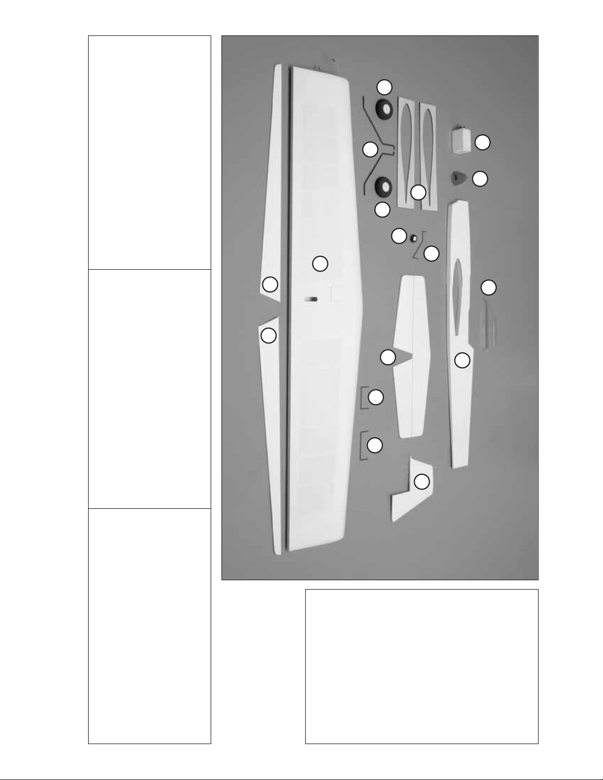
PARTS PHOTOGRAPHED
1. Flaps
2. Wing
3. Hor izontal Stabilizer
with Elevators
4. Fuselage
5. Fin
6. Canopy
7. Main Landing Gear (2)
8. 2-1/2" [65mm] Main Wheels (2)
9. Tail Gear Wire
10. Tail Wheel
11. Fuel Tank
12. Flap Joiner Wire
13. Elevator Joiner Wire
14. 1/8" [3mm] Plywood Flap
Aligning Jig (2)
15. Spinner
PARTS NOT PHOTOGRAPHED
(2) Nylon Tie Straps
(1) 2-56 x 18" [458mm] Pushrod (Elevator)
(1) 2-56 x 6" [153mm] Pushrod (Flaps)
(2) Nylon Clevises
(6) 4-40 x 1-1/2" [38mm] Socket Head Cap
Screws (2-Main Gear, 4-Engine Mounting)
(6) 4-40 Nylon Lock Nuts (2-Main Gear, 4-Engine
Mounting)
(8) #4 Flat Washers (Gear Mounting)
(4) 5-32" [4mm] Wheel Collars (Main Wheels)
(1) 5-64" [2mm] Wheel Collar (Tail Wheel)
(5) 6-32 Set Screws (Wheel Collars)
(1) #2 x 1/2" [13mm] Screw (Pushrod Standoff)
(2) #2 x 3/4" [19mm] Machine Threaded Screws
(Flap Control Horn)
(2) #2 x 1/2" [13mm] Machine Threaded Screws
(Elevator Control Horn)
(4) #2 x 1/4" [6mm] Screws (Hatch on Wing)
(2) #2 x 5/8" [16mm] Screws (Tail Gear)
(2) Nylon Hump Straps
(1) Nylon Flat Strap
(1) Hinge Strip Material
(2) Silicone Clevis Retainers
(1) Bell Crank with Leadouts (Factory Installed)
(1) Metal Pushrod Standoff
(2) Large Nylon Control Horns with Backplates
(2) Decal Sheet
KIT CONTENTS
1
1
8
7
14
8
10
9
2
11
15
6
3
4
13
12
5
Page 6
BUILDING INSTRUCTIONS
Assemble the Main Wing
❏ 1. Locate the 4" [102mm] Flap Joiner Wire. There
is a notch in the trailing edge (TE) of the wing saddle
where this wire will rest. Slide the wing in place while
holding this joiner as shown above .Be sure the hatch
in the wing is on the top.
❏ 2. Center the wing laterally (B=B). Insert a T-pin
through the top, center of the fuselage over the tail.
Tie a loop in one end of a 36" [1m] piece of non-
elastic string such as monofilament or Kevlar cable
(SULQ3223).Slip the loop in the string over the T-pin.
❏ 3. Fold a piece of masking tape over the string
near the other end and draw an arrow on it or mark
the string with a black marker. Slide the tape along
the string and align the arrow with one end of the
wing as shown in the sketch, or make a mark where
the string crosses the wing. Swing the string over to
the other end of the wing and hold it in the same
position. Keeping the trailing edge of the wing
centered from side-to-side, move the wing tips
forward or back as necessary until the arrow, or mark
aligns with both ends of the wing.
❏ 4.Once the wing is aligned, use a fine point marker
such as a Top Flite Panel Line P en to trace around the
wing. Remove the wing and joiner from the fuselage.
❏ 5.Remove the covering using a sharp, new hobby
knife or a heated soldering iron to cut the covering
from the wing 1/16" [1.6mm] inside the lines. If using
a knife, use a light touch and great care not to cut
into the sheeting under the covering or the wing will
be weakened. Using a soldering iron is preferred
because it melts through the covering without cutting
into the wood.Move the soldering iron fast enough to
melt through the covering without burning the wood.
After cutting the covering, use denatured alcohol and
a tissue to clean the ink lines from the covering.
Then, peel off the covering.
- 6 -
A=A B=B
A
B
B
A
Page 7

❏ 6.Mix up a batch of 30-minute epoxy. Slide the wing
most of the way into the fuselage.Apply epoxy to the
inside of the wing saddle and to the wing where it
contacts the fuselage.Slide the wing into position with
the joiner wire. Be careful not to let epoxy come in
contact with the flap joiner wire. If you are
uncertain about the flap joiner wire, you can coat
the center of the wire with petroleum jelly to
prevent the epoxy from securing it in place. Verify
the alignment of the wing as done in step 3. Ensure
the wing remains perpendicular to the fuselage as
shown in the sketch. Use small balsa sticks and/or
paper towels and alcohol to wipe up excess epoxy.
Allow the epoxy to fully harden before proceeding.
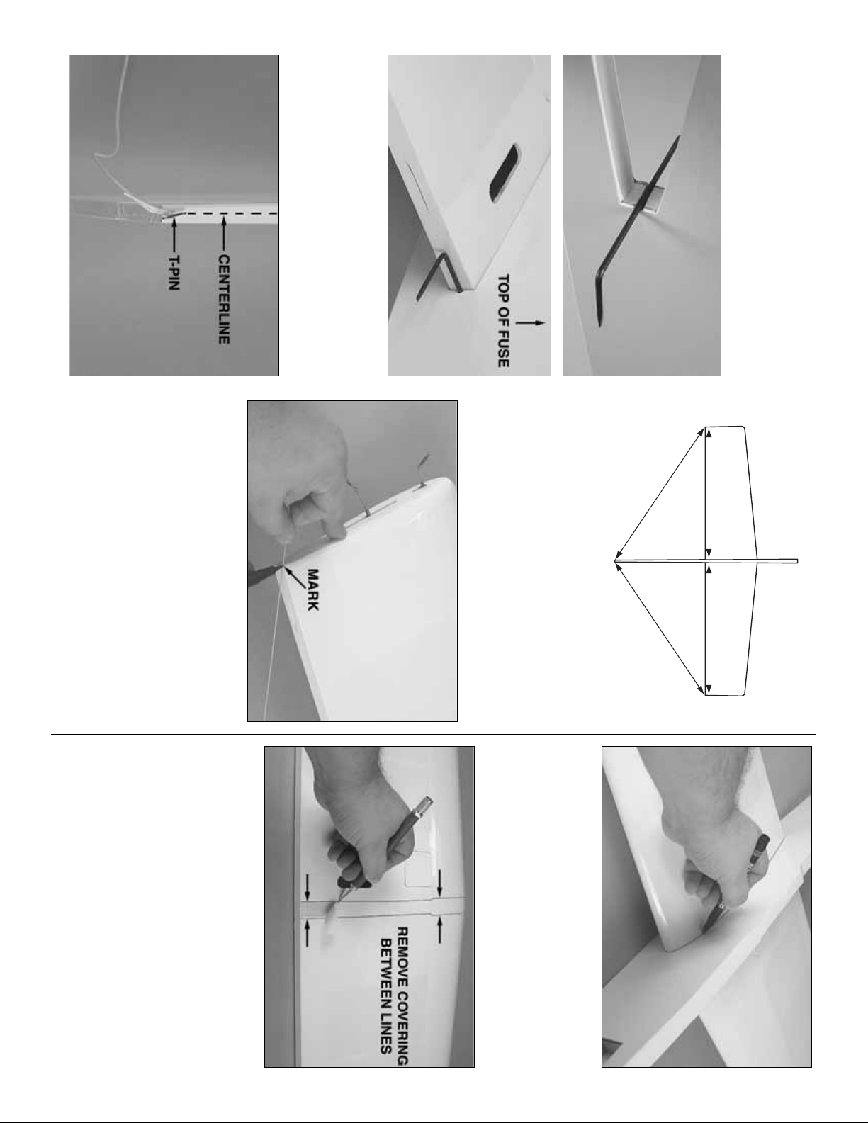
Install the Horizontal Stabilizer
❏ 1.Remove the covering from the stab slot using a
sharp hobby knife.
❏ 2. Measure and mark the centerline of the TE of
the stab.Also mark a spot on the centerline on the aft
end of the fuse. Test fit the stab aligning the mar ks
you just made.
❏ 3. Slide the stab into position. For now, center the
stab in the fuselage as best as you can by “e y e .” Stand
approximately ten feet behind the model and view the
alignment of the stab and wing.If the stab is not parallel
with the wing, place a small weight on the “high side”of
the stab to bring it into alignment. If weight is not
enough, remove the stab from the fuselage and lightly
trim or sand the stab saddle as necessary until you can
get the stab to align with the wing.
❏ 4.Now that the stab is level with the wing, center the
trailing edge of the stab in the fuselage by measuring
from both tips to the center of the fuselage.Make sure
“A” = “A” on both sides of the stab as indicated in the
sketch.Stick pins into the stab near the trailing edge on
both sides of the fuselage. This will keep the trailing
edge of the stab centered.
❏ 5. Insert a pin through the top, center of the
fuselage on the nose of the fuselage. Tie a loop in
one end of a 36" [920mm] piece of non-elastic string
such as monofilament or Kevlar cable (SULQ3223).
Slip the loop in the string over the T-pin.
❏ 6. Fold a piece of masking tape over the string near
the other end and draw an arrow on it or mark the
string with a black marker. Slide the tape along the
string and align the arrow with one end of the stab as
shown in the sketch, or make a mark where the string
crosses the stab.Swing the string over to the other end
of the stab and hold it in the same position.Keeping the
trailing edge of the stab centered from side-to-side,
move the wing tips forward or back as necessary until
the arrow, or mark, aligns with both ends of the stab.
❏ 7.The same as was done for the wing, use a fine-
point felt-tip pen to mark the outline of the fuselage
all the way around both sides of the stab. Then, cut
and remove the covering from the center-section.
❏ 8.Mix up a small batch of 30 minute epoxy and coat
the areas that you removed co v ering from on the stab .
Slide the stab into the mounting slot. Clean up excess
epoxy with a paper towel and alcohol. Be sure to
check the alignment PRIOR to the epoxy hardening.
- 7 -
90˚
AA
AA
Page 8

Attach the Elevators
❏ 1. Locate the Elevator Joiner Wire and the two
elevator halves.
❏ 2. Remove the covering from the precut groove in
the LE of the elevator halv es .Test fit the joiner wire in
both elevator halv es.The ele v ator halv es should both
lay flat with the joiner installed. If they do not, you
may “tweak” the wire to get both halves to lay flat
when joined.
❏ 3.Use a piece of wire or a toothpick to apply epoxy
in the holes and grooves in the elevators for the
joiner wire. Insert the joiner wire into both elevators.
Wipe away excess epoxy as it squeezes out.
❏ 4.Insert 3 hinges into each elevator half and install
the elevator assembly on the stab. Inser t T-pins into
the center of each hinge to keep them centered.
❏ 5. Using thin CA, glue each hinge in place. Apply
6 drops of CA on each hinge, top and bottom. After
the glue has cured, pull on the elevator halves to be
sure the hinges are glued securely in place. Apply
more CA if necessary.
❏ 6.Using masking tape, hold the elevators in place
ensuring they remain parallel to each other when
viewed from behind.
❏ 7. Allow the epoxy to fully harden on the elevator
halves before proceeding.
Attach the Fin
❏ 1.Test fit the fin. Make note of where the elevator
joiner wire comes in contact with the fin.You will need
to make a small notch to allow the elevator joiner
wire to rotate freely at this location and allow the fin
to rest flush against the fuselage for gluing. Remove
the fin and coat the notch with thin CA to fuelproof
the exposed wood.
❏ 2.Check where the fin contacts the fuselage once you
have it aligned.Mark the outline of the fin on the fuselage
and remove the covering between these marks.
❏ 3. Glue the fin in place as shown using 30 minute
epoxy.The leading edge of the fin should be centered
on the fuselage. Ensure the fin is perpendicular (at a
90° angle) to the horizontal stabilizer.Use T-Pins and
masking tape to hold the fin in place until the epoxy
fully hardens.
- 8 -
Page 9

Install the Flaps
❏ 1.Without using any glue, test fit the flap to the joiner
wire and install 4 hinges. If necessary, use a hobby
knife to enlarge any hinge slots that are too tight.
❏❏2. Remove the flaps. Mix up a small batch of 30
minute epoxy. Use a piece of wire or a toothpick to
apply epoxy in the hole and groove in the flap for the
joiner wire. Join the flaps to the wing with the joiner
wire and hinges. Slide the 1/8" [3mm] Die-Cut Ply
Flap Aligning Jig over the wing and flap until it is
snug and no gaps are present. Do this for both wing
halves. Once they are in place, the aircraft can rest
on these jigs.
❏❏3. Once the epoxy has fully hardened, remove
the jigs and apply thin CA to the hinges. Do not
use accelerator.
❏❏4. View the trailing edges of the flaps from the
end of the wing.See if the flaps are parallel with each
other (have the same “up” and “down”). If necessary,
carefully “tweak” the joiner wire to align the flaps.
Connect the Flap Pushrod
❏ 1.Remove the hatch on the left wing panel so you
can see the bellcrank below.
❏ 2. Locate the 6" [152mm] 2-56 pre-bent flap
pushrod. Thread a nylon clevis approximately 14
turns onto the threaded portion. Slide a silicone clevis
retainer onto the clevis as shown.
❏ 3. Slide the pushrod through the slot provided in
the wing. It should exit in the center of this slot.
❏ 4. Insert the bent por tion of the pushrod into the
last hole on the bell crank as shown.
❏ 5. Align the control horn holes with the hinge line.
Mark the location of the holes in the base of the
control horn.Drill 1/16" [1.6mm] holes at these marks.
Attach the control horn and base using two #2 x 3/4"
[19mm] machine threaded screws.
- 9 -
Page 10

❏ 6. Adjust the clevis on the flap pushrod so the
flaps will be centered when the bell crank is neutral.
Hint: The jigs you used to align the flaps can also be
used here to position the flaps at center and hold
them there while you adjust the flap pushrod.
Connect the clevis to the top hole in the control horn.
Slip the retainer over the clevis.
Connect the Elevator Pushrod
❏ 1.Locate the 18" [460mm] 2-56 pre-bent elevator
pushrod wire.
❏ 2.Insert the bend end into the second hole on the
flap control horn as shown.
❏ 3. Locate the white metal standoff and slide it
over the elevator pushrod. On the fuselage you will
notice a darker square showing through the covering.
In the center of this block, drill a 3/64" [1.2mm] pilot
hole. Be careful not to go all the way through the
fuselage. Attach the metal standoff to the fuselage
using one #2 x 1/2" [13mm] self-tapping screw.
❏ 4.Thread a nylon clevis and silicone retainer onto
the threaded portion of the pushrod.
❏ 5. Align the elevator control horn holes with the
hinge line as you did with the flap control horn. Mark
the location of the holes in the base of the control
horn on the elevator. Drill 1/16" [1.6mm] holes at
these marks. Attach the control horn and base using
two #2 x 1/2" [13mm] machine threaded screws.
❏ 6.Adjust the clevis on the elevator pushrod so the
elevators will be centered when the bell crank is
neutral. Connect the clevis to the 3rd hole in the
control horn. Slip the retainer over the clevis.
❏ 7.Use four #2 x 1/4" [6mm] self-tapping screws to
attach the hatch to the opening above the bellcrank
in the wing. Remove the screws and harden the
holes with thin CA. Allow the glue to dry completely
before reinstalling the hatch.
- 10 -
4TH HOLE
2
1
3
RD HOLE
ND HOLE
ST HOLE
Page 11

LANDING GEAR INSTALLATION
Install the Main Gear
❏❏1. Locate the 5/32" [4mm] landing gear wire.
❏❏2. Slide a 5/32" [4mm] wheel collar over the
axle, followed by a 2-1/2" [65mm] main wheel, then
another wheel collar.Insert a 6-32 set screw into each
wheel collar and tighten to attach the wheel as shown.
❏❏3. Remove the wheel and wheel collars and
using a rotary tool such as a Dremel
®
, grind flat spots
on the axle where the set screws will rest.
❏❏4. Reassemble the gear, using Threadlocker on
the set screws to prevent them from backing out. Add
a drop of oil to the axle to ensure the wheel spins freely .
❏❏5. Locate the two 5/32" [4mm] holes on each
side of the fuselage just forward of the main wing and
remove the covering using a shar p hobby knife.
❏❏6. Inser t one of the gear legs as shown in the
hole.The gear should point straight down Note: due
to wood possibly compressing or expanding during
shipment, you may have to widen the hole slightly to
allow the gear to seat fully.
❏❏7. Position one nylon humped landing gear
bracket at the midpoint of the gear leg. Mark the
holes on the fuselage you will need to drill.
❏❏8. Drill two 1/8" [3mm] holes at these marks all
the way through the fuselage.Wic k some thin CA into
the holes to harden them. Attach the strap to the
fuselage using two 4-40 x 1-1/2" [38mm] socket
head cap screws.On the other side of the fuselage,
slide the landing gear strap over the two socket head
cap screws and attach two 4-40 nylon locknuts to
the ends of the screws.Tighten the screws down to
hold the gear in place. Be careful not to over tighten.
- 11 -
Page 12

Install the Tail Gear
❏ 1. Locate the 5/64" [2mm] tailgear wire and the
small wheel collar.
❏ 2. Mount the tail wheel to the pre-bent tail gear
wire with the small wheel collar and a 6-32 set screw .
Use Threadloc k er on the set scre w bef ore installing it
into the collar.
❏ 3. Drill a 5/64" [2mm] hole at the position shown in
the photo 6" [153mm] from the fuselage tail and 1/2"
[13mm] from the bottom of the fuselage.
❏ 4. Insert the tail gear wire as shown into the hole.
It may be necessary to trim the wire so it does not
come out the other side of the fuselage. Mix a small
batch of 30-minute epoxy and fill the hole for the tail
gear wire with epoxy and hold the tail wire in place
with tape while the epoxy hardens. Locate the nylon
gear strap. Secure the tail wire to the fuselage using
the nylon gear strap and two #2 x 5/8" [16mm] self-
tapping screws.Remove the screws and harden the
holes with thin CA.Allow the CA to harden completely
before re-installing the screws.
ENGINE INSTALLATION
❏ 1. Our test models were flown using the O.S. .40
and .46 LA C/L engines.If you choose to use another
brand of engine, you will need to test fit the engine
and mark the location of the engine mounting holes.
Be sure the front of the thrust washer clears the
fuselage.The engine mounting rails may need to be
sanded to accommodate other brands of engines.
❏ 2. If you are using an O.S. engine, the engine
mounting bolt holes have been started for you as a
guide. Locate the four holes on each side of the
fuselage by lightly rubbing the covering with your
finger and feeling for the holes. Use a T-pin to poke
the covering to verify you have found the hole.
Remove the covering from the hole using a sharp
hobby knife. Drill 1/8" [3mm] holes through the
engine mounting rails at the marks for your engine to
allow the engine mounting bolts to pass through.
Laying a small block of wood on the back side of the
fuselage when drilling will help prevent the wood
from splintering. Strengthen these holes by wicking
some thin CA into them.
❏ 3.Using four 4-40 x 1-1/2" [38mm] socket head cap
screws, 4-40 nylon lock nuts, and eight #4 washers,
mount the engine to the fuselage.
- 12 -
Page 13

FUEL T ANK INST ALLA TION
Assemble the Fuel Tank
❏ 1.Remove the rubber stopper from the fuel tank.
The hardware for the fuel tank is located inside of it.
Shake the fuel tank lightly to get the hardware out.
Inside there is a fuel clunk, three aluminum tubes,
and a 3" [76mm] length of silicone fuel tubing.
NOTE: You will only use two of the metal tubes for
the control line fuel tank setup.
❏ 2. Insert two metal tubes through the openings in
the stopper assembly as shown. Be sure that the
bottom plate is on the stopper assembly when you
insert the tubes. Bend one of the tubes slightly. All
tubes except for the long bent tube should protrude
from the stopper 1/2" [13mm].The long end does not
need to be any specific length.
❏ 3.Cut the silicone fuel tubing to 2" [51mm] in length
and attach the fuel clunk.
❏ 4. Slide the stopper assembly into the fuel tank.
The bent tube should point upward.The clunk should
move freely, but rest against the back of the tank
when the stopper is in place. Make note of which of
the tubes is bent inside the tank. This will be your
vent line that is connected to the muffler.The other
line is connected to the carburetor on the engine.
Mount the Fuel Tank
❏ 1.Locate the four mounting slots for the fuel tank.
Remove the covering from these slots with a shar p
hobby knife. Wick some thin CA into the slots to
fuelproof the exposed wood.
❏ 2.Using the twon ylon tie straps pro vided, attach
the fuel tank to the fuselage.The vent line should be
towards the top of the fuselage.
Hint: A small strip of
double-sided foam tape could be used between the
fuselage and the fuel tank to help hold the fuel tank
in place.
- 13 -
TO CARB
FUEL CLUNK
TO VENT
TOP OF TANK
Page 14

❏ 3. Cut 4"[102mm] and 3" [77mm] lengths of fuel
tubing. Connect the shor ter length to the carburetor
and the fuel line.The longer piece connects the vent
line to the muffler which can now be mounted.
FINAL DETAILS
Prop Installation and Control
Surface Check
❏ 1. Attach the prop and spinner to the engine.
❏ 2. Be certain that the flaps are centered when
the elevators are centered. Also be cer tain that all
the pushrods are connected and that the flaps
and elevator are operating smoothly. Make any
adjustments necessary.
Mount the Canopy
❏
1.Use scissors to cut out the canopy front and rear.
❏ 2.Test fit the canop y and trim it to the desired shape.
Be sure to leave enough overlap for the next step.
❏ 3. Mount the canopy to the fuselage with 1/4"
[6mm] white striping tape or Canopy Glue. Do not
use CA as it will attack the clear canopy, causing it to
fog over and become soft.
Apply the Decals
Prior to applying decals, use a covering iron with a
covering sock to remove any wrinkles in the covering
on the wing and flaps.The best way is to glide the iron
over the covering until the wrinkles disappear, and
then go over the area again, pushing down to bond
the covering to the wood. If the wrinkles don’t go
away, the balsa in that area may be bending inward.
If this is happening, do not press down on the iron in
that area. Simply let the heat of the iron shrink the
covering. If the wrinkles momentarily disappear, then
immediately reappear, the iron may be too hot, thus
causing air bubbles.Lower the temperature of the iron
or use a sharp #11 blade to puncture several holes in
the covering, and then reheat. The suggested iron
temperature is around 360° F
❏ 1. Use scissors or a shar p hobby knife to cut the
decals from the decal sheet. Where possible, round
the corners so they are less likely to peel up during
cleaning and handling.
- 14 -
Page 15

❏ 2. Be certain the model is clean. Prepare a
dishpan or small bucket with a mixture of liquid dish
soap and warm water–about 1/2 teaspoon of soap
per gallon of water. Submerse one of the decals in
the solution and peel off the paper backing. Note:
Even though the decals have a “sticky-back” and are
not the water transfer type , submersing them in soap
and water allows accurate positioning and reduces
air bubbles underneath.
❏ 3.Position the decal on the model where desired.
Holding the decal down, use a paper towel to wipe
away most of the water.
❏ 4. Use a piece of soft balsa or something similar
to squeegee remaining water from under the decal.
Apply the rest of the decals the same way.
GET THE MODEL READY TO FLY
Balance the Model (C.G.)
At this stage the model should be completely ready-
to-fly with all of the components installed including
the engine, muffler, propeller, spinner, landing gear
and wheels.
❏ 1.If using a Great Planes C.G.Machine to balance
the model, set the rulers to 3" [76mm]. If not using a
C.G. Machine, use a fine-point felt-tip pen or 1/8"
wide tape to accurately mark the recommended C.G.
(center of gravity, or “balance point”) on the bottom of
the wing 3" [76mm] back from the leading edge on
both sides of the fuselage.
❏ 2. Place the model on a Great Planes CG
Machine, or lift it at the balance point you marked on
both sides of the fuselage. Note whether the nose or
tail drops. If the tail drops, the model is “tail heavy”
and weight must be added to the nose to balance.If,
howev er, the nose drops, then weight must be added
to the tail to balance.
❏ 3.Add nose or tail weight to balance the model.If
nose weight is required it may be added by using a
“spinner weight” (GPMQ4645 for the 1 oz. [30g]
weight, or GPMQ4646 for the 2 oz. [55g] weight) or
Great Planes (GPMQ4485) “stick-on” lead which
may be added to the nose.If tail weight is required it
may be placed on the right side of the fuselage
(opposite the muffler) under the stabilizer.
NOTE: Do not rely upon the adhesive on the back of
the lead weight to permanently hold it in place. Over
time, fuel and exhaust residue ma y soften the adhesive
and cause the weight to fall off. Use #2 sheet metal
screws, RTV silicone or epoxy to permanently hold the
weight in place.
Balance the Propeller
Carefully balance your propeller and spare propellers
before you fly. An unbalanced prop can be the single
most significant cause of vibration that can damage
your model.Not only will engine mounting screws and
bolts loosen, possibly with disastrous effect, but
vibration can also cause your fuel to foam, which will,
in turn, cause your engine to run hot or quit.
We use a Top Flite Precision Magnetic Prop Balancer
™
(TOPQ5700) in the workshop and keep a Great Planes
Fingertip Prop Balancer (GPMQ5000) in our flight box.
Engine Check
If the engine is new , follow the engine manufacturer’s
instructions to break-in the engine. After break-in,
confirm that the engine runs reliably and smoothly
and maintains full power indefinitely. After you run
the engine on the model, inspect the model closely
to make sure all screws remained tight, the hinges
are secure and the prop is secure.
Control Check
With the lines connected to the lead-outs and your
assistant holding the model, operate the controls to
make sure they move smoothly. If any binding or
hesitation is detected, inspect the model and
eliminate the problem.
Adjust Leadouts
The Top Flite Tutor II ARF is equipped with adjustable
leadouts. The lines can be adjusted by means of a
Phillips head set screw located inside the slot provided
for the lead outs.The leadouts can be loosened, then
slid fore and aft.When they are in place , tighten the set
screw down to prevent the leadouts from moving back
and forth in flight.You should also check the leadouts
after each flight, making sure each screw is tight.
IMPORTANT: If you found it necessary to add
any weight, recheck the C.G. after the weight
has been installed.
The C.G. range for the Top Flite Tutor II ranges
2-3/4" [70mm] to 3-3/8" [83mm] from the LE.
The recommended starting C.G. is 3" [76mm]
back from the LE of the wing at the fuselage.
This is the midpoint of the C.G.range specified.
- 15 -
Page 16

As a general guideline, positioning the leadouts further
aft makes plane pull harder on lines (for windy days),
but also makes plane “handle” or react a little slower.
This positioning is recommended for less-powerful
engines or longer lines and is also a good way to
counter the effect of having not enough wing tip weight.
Further forward makes plane pull less hard on lines,
thus quickening response. This can be better for
calm days, better f or f aster , more pow erful engines or
shorter lines. It is also a way to counter the effect of
having too much wing tip weight.
The exact placement of these leadouts will be a matter
of experimentation to match your flying style;however ,
we recommend centering the two leadouts in their
slots as a starting point.
ENGINE SAFETY PRECAUTIONS
Keep all engine fuel in a safe place, away from high
heat, sparks or flames, as fuel is very flammable.Do
not smoke near the engine or fuel; and remember
that engine exhaust gives off a great deal of deadly
carbon monoxide.Therefore , do not run the engine in
a closed room or garage.
Get help from an experienced pilot when learning to
operate engines.
Use safety glasses when starting or running engines.
Do not run the engine in an area of loose gravel or
sand; the propeller may throw such material in your
face or eyes.
Keep your face and body as well as all spectators
away from the plane of rotation of the propeller as
you start and run the engine.
Keep these items aw a y from the prop:loose clothing,
shirt sleeves, ties, scarfs, long hair or loose objects
such as pencils or screwdrivers that may fall out of
shirt or jacket pockets into the prop.
Use a “chicken stick” or electric starter to star t the
engine. Do not use your fingers to flip the propeller.
Make certain the glow plug clip or connector is
secure so that it will not pop off or otherwise get into
the running propeller.
Make all engine adjustments from behind the
rotating propeller.
The engine gets hot! Do not touch it during or right
after operation. Make sure fuel lines are in good
condition so fuel will not leak onto a hot engine,
causing a fire.
To stop the engine, cut off the fuel supply by closing
off the fuel line or following the engine manufacturer’s
recommendations. Do not use hands, fingers or any
other body part to try to stop the engine .Do not throw
anything into the propeller of a running engine.
AMA SAFETY CODE (EXCERPTS)
Read and abide by the following Academy of Model
Aeronautics Official Safety Code:
General
1. I will not fly my model aircraft in sanctioned e vents ,
air shows, or model flying demonstrations until it
has been proven to be airworthy by having been
previously successfully flight tested.
3.Where established, I will abide by the safety rules
for the flying site I use, and I will not willfully and
deliberately fly my models in a careless, reckless
and/or dangerous manner.
5. I will not fly my model unless it is identified with
my name and address or AMA number, on or in
the model.
7. I will not operate models with pyrotechnics (any
device that explodes , burns, or propels a projectile
of any kind).
8. I will not consume alcoholic bev erages prior to , nor
during, participation in any model operations.
9. Children under 6 years old are only allowed on the
flight line as a pilot or while under flight instruction.
Control Line
1. I will subject my complete control system (including
safety thong, where applicable) to an inspection
and pull test prior to flying. Pull test will be in
accordance with the current Competition
Regulations for applicable model category. Models
not fitting a specific category as detailed shall use
those pull test requirements for Control Line
Precision Aerobatics.
2. I will assure that my flying area is safely clear of all
utility wires or poles.
3. I will assure that my flying area is safely clear of all
non-essential participants and spectators before
permitting my engine to be started.
4. I will not fly a model closer than 50 feet [15m] to
any electrical power line.
- 16 -
Page 17

CHECKLIST
❏ 1.Make sure areas exposed to fuel or exhaust
residue have been fuel proofed.
❏ 2. Check the C .G.according to the measurements
and procedure provided in the manual.
❏ 3. Use thread-locking compound on the set scre ws
in the wheel collars that hold on the wheels.
❏ 4. Add a drop of oil to the axles so the wheels will
turn freely.
❏ 5.Mak e sure all hinges are securely glued in place.
❏ 6.Use thin CA to harden all screw holes
throughout the airplane.
❏ 7. Confirm that the flaps and elevators operate
freely and smoothly by pulling on the lead-outs.
❏ 8. Make sure the fuel lines are connected and
are not kinked.
❏ 9. Balance your propeller and spare propellers.
❏ 10.Tighten the propeller nut and spinner.
❏ 11. Place your name, address, AMA number and
telephone number on your model.
❏ 12. If you wish to photograph your model, do so
before the first flight.
FLYING
Preflight
NOTE: The Top Flite Tutor II ARF is not a beginner’s
model. It is intended for beginning to advanced stunt
pilots who have had some previous control line
experience. If you are an inexperienced pilot, seek
the assistance of a knowledgeable control line pilot
who can help you with your first flights.
Beginning stunt pilots should make their first flights in
calm or low wind conditions. Stronger winds may
blow the model inward which will decrease line
tension resulting in loss of control.If the lines ever do
go slack, quickly step back to tighten the lines and
regain control. Of course, this is most likely to
happen, and should be expected, as the model
approaches the upwind half of the circle.
Place the model and starting equipment where the wind
will be behind the model when it is released for takeoff.
For the first half-circle (during the brief period when
the pilot has the least control before the model is “up
to speed”) the wind will push the model outward to
maintain line tension.
Mark the center of the flying circle with paint, chalk or
a suitable object (such as a shop towel) so you won’t
wander.This is especially important if the flying area
is limited.
With your assistant holding the model, walk from the
model toward the handle in the center of the circle
while using your fingers to keep the lines separated.
This will ensure that the lines are not twisted and are
free to operate the controls.
While the pilot is holding the lines, the assistant should
walk the model once around the circle to be certain
the flight path is clear and to double-check that there
are no obstructions that could snag the lines.
The pilot should double-check the operation of the
controls by pulling and pushing on the handle and
having the assistant signal what the controls are doing
(“up” and “down”).
Takeoff
When both the pilot and assistant are ready , the model
may be fueled and started.Once the engine is running
and the model is ready to be released, the assistant
should point the nose of the model slightly away from
the inside of the circle.This will help keep the lines taut
for the first few feet until the model gets going.
Upon the pilot’s signal, the assistant may release the
model–never push the model forward as doing so
may result in a crash.
The pilot should be ready–especially during takeoff–to
briefly step back to maintain line tension until the
model has gained enough air speed to achieve line
tension on its own.Allow the model to roll out and gain
enough speed to become airborne. When enough
speed has been gained, the pilot may raise his arm
slightly, giving “up” elevator command, thus allowing
the model to leave the ground.
Once the model has lifted, maintain a slow and steady
climb until a comfortable altitude has been reached
(usually between “eye-level” and approximately ten
feet in the air).The lines must remain taut throughout
the entire flight. If the lines ever do go slack, the pilot
will not have control of the model. During most
situations the model’s f actory built-in features will allow
it to maintain good line tension, but on occasions
when the wind blows the model inward or the model
becomes too slow the modeler must anticipate or
notice a decrease in “pull” and quickly step backward
to tighten the lines and regain control.
To climb, the pilot will slowly raise his arm.T o descend,
the pilot will slowly lower his arm. To maintain level
flight the pilot will hold his arm horizontally. Beginning
- 17 -
Pilot
Takeoff
Spot
Direction
Wind
Page 18

pilots should control the model by keeping their arms
straight and bending at the elbow with little or no wrist
movement. Later, when they become more
experienced, wrist movement may be increased to
increase control response.All control inputs should be
smooth. Continue flying the model in a level attitude,
getting used to how the controls react and how the
model “feels.”Do this until the engine r uns out of fuel.
Actual flight time depends on several factors, such as
the engine size and brand, needle valve setting,
propeller size, fuel, atmospheric conditions, etc., but
you can expect flight times around 7-8 minutes.
Landing
When the engine starts to sputter and/or speed up,
this is an indication that the tank is nearly empty.
Continue to fly the model in a level attitude until the
engine finally quits.The same as any time the model
slows, the pilot should step back to k eep the lines taut
and maintain control.Allow the model to descend until
it is about two feet off the ground. When the model
has lost nearly all flying speed and is a foot or two
from the ground, the pilot should raise his arm to keep
the lines taut and apply full up elevator, allowing the
model to gently touch down.
After the model has come to a stop the assistant may
retrieve the model and return it to the starting area.
In doing so the lines should be kept taut so they do
not become twisted or entangled.
Clean the model using paper towels and household
cleaner to wipe off exhaust residue. Inspect the
model thoroughly, looking for loose fasteners and
signs of damage or fatigue.Also make sure the prop
has not been damaged. Perform any maintenance
necessary to prepare the model for the next flight.
At the end of the flying session any unspent fuel
should be drained from the tank.
After you have become familiar with the way your
Tutor II ARF flies and you are ready to begin
performing stunts, seek the assistance of an
experienced stunt pilot before attempting to learn new
maneuvers on your own.Almost any control line stunt
maneuvers are started with the model downwind from
the pilot, i.e.wind on the pilot's back.Consult the AMA
Control Line section for stunt maneuvers.
One final note about flying your model:Have a goal or
flight plan in mind for ev ery flight.This can be learning
a new maneuver(s), improving a maneuver(s) you
already know, or learning how the model behaves in
certain conditions (such as when testing different
propellers or fuel). This is not necessarily to improve
your skills (though it is never a bad idea!), but more
importantly so you do not surprise yourself by
impulsively attempting a maneuver and suddenly
finding that you’ve run out of time, altitude or
airspeed. Ever y maneuver should be deliberate, not
impulsive. For example, if you’re going to do a loop,
check your altitude and mind the wind direction. A
flight plan greatly reduces the chances of crashing
your model just because of poor planning and
impulsive moves. Remember to think!
Have a ball, keep the lines taut and always fly in
a safe manner.
GOOD LUCK, GREAT FLYING, AND HAVE FUN!
O.S. Engines
®
.40 LA-S Control Line Engine with Muffler
(OSMG1440)
.46 LA-S Control Line Engine with Muffler
(OSMG1446)
The O.S..40 and .46 LA-S offer the proven power of
LA Series R/C sport engines – but are engineered for
the special requirements of control line flying,
replacing the carburetor with a venturi that keeps the
engine running at a constant speed. A remotely
mounted needle valve keeps your hands safely
distanced from the spinning prop during adjustments.
An O-ring helps seal the needle against fuel and air
leaks, while heavy-duty webbing reinforces the blue-
finish, one-piece crankcase in high-stress areas.
Includes E-3030 muffler, muffler mounting screws,
#A3 glow plug, and 2-year warranty.Fuel with 10-20%
nitro and 18% oil content recommended.
- 18 -
Page 19

- 19 -
AMA STUNT MANEUVERS
Here are some of the AMA Stunt Maneuvers. Refer
to the AMA Rule Book for full descriptions.
Takeoff
Reverse Wingovers
Consecutive Inside Loops
Inverted Flight
Consecutive Outside Loops
Consecutive Inside Square Loops
Consecutive Outside Square Loops
Consecutive Inside Triangular Loops
Horizontal Eights
Page 20

FLIGHT LOG
DATE COMMENTS
Started Assembly
Finished Assembly
First Flight
First Loop
First Inverted Flight
First Wingover
 Loading...