

Page 1
WARRANTY.....Top Flite
®
Models guarantees this kit to be free from defects in both material and workmanship at the date of purchase.This warranty
does not cover any component parts damaged by use or modification.In no case shall Top Flite’s liability exceed the original cost of the purchased kit. Further, T op Flite
reserves the right to change or modify this warranty without notice. In that Top Flite has no control over the final assembly or material used for final assembly, no liability shall
be assumed nor accepted for any damage resulting from the use by the user of the final user-assembled product. By the act of using the user-assembled product, the user
accepts all resulting liability .If the buyer is not prepared to accept the liability associated with the use of this pr oduct,the buyer is advised to return this kit immediately
in new and unused condition to the place of purchase.
Top Flite Models Champaign, IL Telephone (217) 398-8970, Ext. 5 airsupport@top-flite.com
READ THROUGH THIS INSTRUCTION BOOK FIRST. IT CONTAINS IMPORTANT INSTRUCTIONS AND WARNINGS CONCERNING THE ASSEMBLY AND USE OF THIS MODEL.
TOPZ9300 for TOPA1005 V1.0
Entire Contents © Copyright 2003
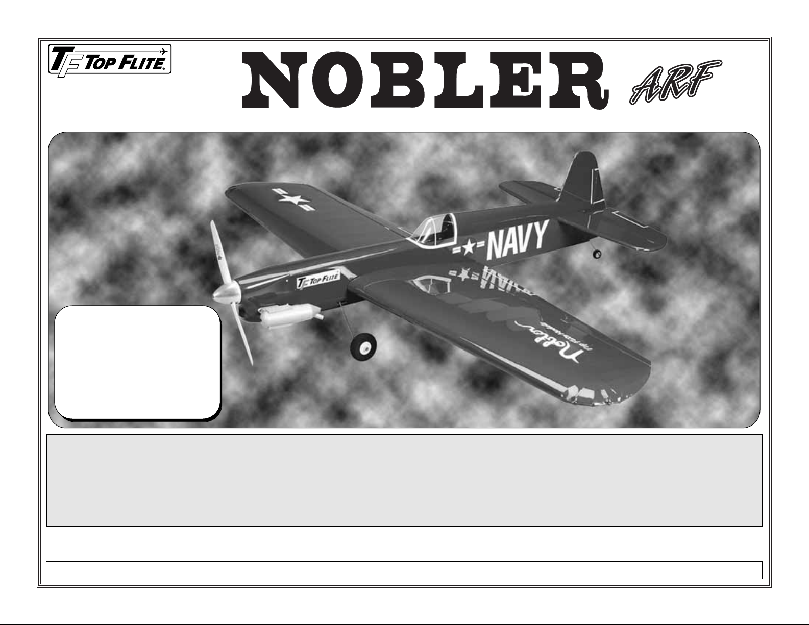
Wingspan: 50.5 in [1,285mm]
Wing Area: 500 sq in [32.2 dm2]
Weight: 42 – 50 oz [1,190 – 1,420g]
Wing Loading: 12 – 14 oz/sq ft
[37 – 43 g/dm
2
]
Length: 38.5 in [980mm] (tip of rudder
to tip of spinner)
Engine: .35 – .46 cu in [5.5 – 7.5cc]
2-stroke glow
Page 2
TABLE OF CONTENTS
INTRODUCTION . . . . . . . . . . . . . . . . . . . . . . . . . . 2
IMPORTANT SAFETY PRECAUTIONS . . . . . . . . . 2
ENGINE & LINE RECOMMENDATIONS . . . . . . . . . 3
ADDITIONAL ITEMS REQUIRED. . . . . . . . . . . . . . 3
Hardware & Accessories. . . . . . . . . . . . . . . . . 3
Adhesives & Building Supplies . . . . . . . . . . . . 3
Optional Supplies & Tools . . . . . . . . . . . . . . . . 4
Covering Tools . . . . . . . . . . . . . . . . . . . . . . . . 4
KIT INSPECTION. . . . . . . . . . . . . . . . . . . . . . . . . . 4
ORDERING REPLACEMENT PARTS. . . . . . . . . . . 4
KIT CONTENTS. . . . . . . . . . . . . . . . . . . . . . . . . . . 5
IMPORTANT BUILDING NOTES . . . . . . . . . . . . . . 6
ASSEMBLE THE WING . . . . . . . . . . . . . . . . . . . . . 6
Hinge the Flaps . . . . . . . . . . . . . . . . . . . . . . . 6
Make the Flap Pushrod. . . . . . . . . . . . . . . . . . 7
Join the Flaps to the Wing . . . . . . . . . . . . . . . 8
Finish the Wing. . . . . . . . . . . . . . . . . . . . . . . . 9
ASSEMBLE THE FUSELAGE . . . . . . . . . . . . . . . 10
Prepare the Stab . . . . . . . . . . . . . . . . . . . . . 10
Make the Elevator Pushrod . . . . . . . . . . . . . . 12
Mount the Fuel Tank . . . . . . . . . . . . . . . . . . . 12
Join the Wing & Stab to the Fuselage . . . . . . 13
Join the Fin & Tail Wheel. . . . . . . . . . . . . . . . 13
Mount the Main Landing Gear . . . . . . . . . . . . 14
Mount the Engine . . . . . . . . . . . . . . . . . . . . . 14
Mount the Cowl. . . . . . . . . . . . . . . . . . . . . . . 15
FINAL DETAILS . . . . . . . . . . . . . . . . . . . . . . . . . . 17
Mount the Canopy . . . . . . . . . . . . . . . . . . . . 17
Apply the Decals. . . . . . . . . . . . . . . . . . . . . . 17
GET THE MODEL READY TO FLY . . . . . . . . . . . . 17
Balance the Model (C.G.) . . . . . . . . . . . . . . . 17
Wing Tip Weight . . . . . . . . . . . . . . . . . . . . . . 18
PREFLIGHT. . . . . . . . . . . . . . . . . . . . . . . . . . . . . 18
Balance the Propellers . . . . . . . . . . . . . . . . . 18
Engine Check. . . . . . . . . . . . . . . . . . . . . . . . 18
Control Check. . . . . . . . . . . . . . . . . . . . . . . . 19
ENGINE SAFETY PRECAUTIONS. . . . . . . . . . . . 19
AMA SAFETY CODE (excerpt) . . . . . . . . . . . . . . 19
General . . . . . . . . . . . . . . . . . . . . . . . . . . . . 19
Control Line . . . . . . . . . . . . . . . . . . . . . . . . . 19
CHECK LIST . . . . . . . . . . . . . . . . . . . . . . . . . . . . 19
FLYING . . . . . . . . . . . . . . . . . . . . . . . . . . . . . . . . 20
Flying Precautions . . . . . . . . . . . . . . . . . . . . 20
Preflight . . . . . . . . . . . . . . . . . . . . . . . . . . . . 20
Takeoff . . . . . . . . . . . . . . . . . . . . . . . . . . . . . 21
Landing . . . . . . . . . . . . . . . . . . . . . . . . . . . . 22
INTRODUCTION
Congratulations and thank you for purchasing the
Top Flite Control Line Nobler ARF. Originally
designed and flown by the legendary George
Aldrich in the 1950’s, the Nobler is now recognized
as one of the most popular and successful control
line stunt models of all time. While studying the
Nobler’s histor y, it was revealed just how much of a
control line legend the late Mr. Aldrich is. Much of
the fun, success and satisfaction control line pilots
enjoy today can be directly attributed to Mr. Aldrich
and his Nobler. And now, Top Flite merges the past
with the present by bringing this old-time favorite
back to life–only in ARF form. Reincarnated from
original Top Flite plans, the Nobler ARF is a perfect
way to get into beginner stunt flying without the
initial time and money commitment required for
today’s kit-built stunters. And if you plan to just
dabble in control line, the Nobler ARF has the
perfect blend of maneuverability and stability to get
you into the air with minimal assistance from an
experienced flyer.
Note: The Top Flite Nobler ARF pictured on the kit
box cover features a Great Planes 1-3/4" [45mm]
aluminum spinner (not included). However, serious
stunt pilots who wish to reduce the model’s overall
weight should use a lightweight plastic spinner, thus
reducing the amount of tail-weight that would be
required to offset an aluminum spinner.
1.Your Top Flite Nobler ARF should not be considered
a toy, but rather a working model that functions like a
full-size airplane. Because of its performance
capabilities, the Nobler ARF, if not assembled and
operated correctly, could possibly cause injury to
yourself or spectators and damage to property.
2. You must assemble the model according to the
instructions.Do not alter or modify the model, as doing
so may result in an unsafe or unflyable model. In a few
cases the instructions may differ slightly from the
photos. In those instances the written instructions
should be considered as correct.
3. You must take time to build straight, true
and strong.
4. You must use lines that are in first-class condition,
and a correctly sized engine and components
throughout the building process.
5. You must correctly install all pushrods and other
components so that the model operates correctly on the
ground and in the air.
6. You must check the operation of the model before
every flight to insure that all equipment is operating and
that the model has remained structurally sound.
7. If you are not already an experienced control line
pilot, you should fly the model only with the help of a
competent, experienced control line pilot.
8.While this kit has been flight tested to exceed normal
use, if the plane will be used for extremely high stress
flying, such as racing, the modeler is responsible for
taking steps to reinforce the high stress points.
PRO TECT YOUR MODEL,
YOURSELF & OTHERS
FOLLO W THESE IMPORT ANT
SAFETY PRECAUTIONS
- 2 -
Page 3
9. WARNING: The cowl included in this kit is made of
fiberglass, the fibers of which may cause eye, skin and
respiratory tract irritation. Ne v er blo w into an y fiberglass
part to remove fiberglass dust, as the dust will blow
back into your eyes. Always wear safety goggles, a
particle mask and rubber gloves when grinding, drilling
and sanding any fiberglass part and thoroughly vacuum
the part and work area afterward.
Remember: Take your time and follow the
instructions to end up with a well-built model that is
straight and true.
If you have not flown a control line stunt model before,
we recommend that you get the assistance of an
experienced pilot in your club for your first flights. If
you’re not a member of a club, your local hobby shop
has information about clubs in your area whose
membership includes experienced pilots.
In addition to joining a control line club, we strongly
recommend you join the AMA (Academy of Model
Aeronautics). AMA membership is required to fly at
AMA sanctioned clubs.Among other benefits, the AMA
provides insurance to its members who fly at
sanctioned sites and events. Additionally, training
programs and instructors are available at AMA club
sites to help you get started the right way. Contact the
AMA at the following address or toll-free phone number:
Academy of Model Aeronautics
5151 East Memorial Drive
Muncie, IN 47302-9252
Tele. (800) 435-9262
Fax (765) 741-0057
Or via the Internet at: http://www.modelaircraft.org
ENGINE & LINE
RECOMMENDATIONS
ADDITIONAL ITEMS REQUIRED
Hardware & Accessories
In addition to the engine, lines, handle and
connectors previously listed, following is the list of
hardware and accessories required to finish the Top
Flite Control Line Nobler ARF. Order numbers are
provided in parentheses.
❏ 3' [900mm] Standard silicone fuel tubing
(GPMQ4131)
❏ Aluminum fuel line plug (GPMQ4166)
❏ 1-3/4" [45mm] White spinner (GPMQ4505)
-or-
❏ 1-3/4" [45mm] Aluminum spinner (GPMQ4551)
and appropriate adapter (GPMQ4581 for O.S.
MAX LA and other engines with 1/4-28
crankshaft thread)
❏ 1/4" [6mm] White striping tape (GPMQ1610)
❏ 1/16" [2mm] White striping tape (GPMQ1580)
Adhesives & Building Supplies
In addition to common hobby tools and household
tools, this is the “short list” of the most important
items required to build the Top Flite Nobler ARF.
Great Planes®Pro™CA and Epoxy glue are
recommended.
❏ 1/2 oz. [15g] Thin Pro CA (GPMR6001)
❏ Pro 30-minute epoxy (GPMR6047)
❏Threadlocker™thread-locking cement
(GPMR6060)
❏ Silver solder w/flux (GPMR8070)
❏ RTV silicone (for mounting fuel tank)
❏ #1 Hobby knife (HCAR0105)
❏ #11 blades (5-pack HCAR0211, or 100-pack
HCAR0311)
❏ Drill bits: 1/16" [1.6mm], 3/32" [2.4mm], 1/8"
[3.2mm], 9/64" [3.6mm]
❏ 1/8" [3.2mm] K&S brass tube or 1/8" [3.2mm] dril l
❏ Small metal file
❏ Rotary tool such as Dremel®with cutting/grinding
assortment (for cutting holes in fiberglass cowl)
❏ Stick-on segmented lead weights (GPMQ4485)
❏Top Flite Panel Line Pen (TOPQ2510)
❏ Sandpaper assortment
A .35-.46 cu in [5.5-7.5cc] two-stroke glow
engine is recommended for the Top Flite Nobler
ARF. Our test models performed superbly with
the O.S.®MAX .40 LA-S and a Top Flite 11 x 4
Power Point®wood prop. This combination
provided good line-tension and lap times on 60'
lines. A .46 engine could be used as well, but
expect faster speeds with this setup. For most
engines, .015" [.38mm] multi-strand lines are
recommended, but .018" [.46mm] multi-strand
lines are recommended if flying with a .46
engine.
#132 U156 .015" x 60' [.38mm x 18m] lines
(SULP2632)
#135 U186 .018" x 60' [.46mm x 18m] lines
(SULP2635)
#136 U187 .018" x 70' [.46 x 21.3m] lines
(SULP2639)
#166 IJ1 Standard handle (SULP2866)
#148 80 lb. [36kg] test line connectors
(SULP2948–pkg. of 2)
Note: We , as the kit manuf acturer, provide you with
a top quality, thoroughly tested kit and instructions,
but ultimately the quality and flyability of your
finished model depends on how you build it;
therefore, we cannot in any way guarantee the
performance of your completed model, and no
representations are expressed or implied as to the
performance or safety of your completed model.
- 3 -
Page 4
Optional Supplies & Tools
These are some of the items used while building the
Nobler that are not absolutely necessary, but are
mentioned in the manual.
❏ 2 oz. [57g] Spray CA activator (GPMR6035)
❏ 4 oz. [113g] Aerosol CA activator (GPMR634)
❏ CA applicator tips (HCAR3780)
❏ CA debonder (GPMR6039)
❏ Epoxy brushes (6, GPMR8060)
❏ Mixing sticks (50, GPMR8055)
❏ Mixing cups (GPMR8056)
❏ Builder’s Triangle Set (HCAR0480)
❏ Curved-tip canopy scissors for trimming plastic
parts (HCAR0667)
❏ Milled fiberglass (GPMR6165)
❏ Denatured alcohol (for epoxy clean up)
❏ K & S #801 Kevlar®thread (for stab alignment,
K+SR4575)
❏ Hobby Heat™micro torch (HCAR0750)
❏ Dead Center™Engine Mount Hole Locator
(GPMR8130)
❏ CG Machine™(GPMR2400)
❏ Precision Magnetic Prop Balancer™(TOPQ5700)
❏ Prop Reamer (GPMQ5005)
Covering T ools
❏ 21st Century®(COVR2700) or Top Flite
MonoKote®sealing iron (TOPR2100)
❏ 21st Century (COVR2702) or Top Flite Hot Sock
™
iron cover (TOPR2175)
Note: The stabilizer and wing incidences and engine
thrust angles have been factory-built into this model.
However, some technically-minded modelers may
wish to check these measurements anyway. To view
this information, visit the web site at
www.top-
flite.com
and click on “Technical Data.” Due to
manufacturing tolerances which will have little or no
effect on the way the model will fly, there may be
slight deviations between your model and the
published values.
KIT INSPECTION
Before starting to build, take an inv entory of this kit to
make sure it is complete, and inspect the parts to
make sure they are of acceptable quality. If any parts
are missing or are not of acceptable quality, or if you
need assistance with assembly, contact Product
Support. When reporting defective or missing parts,
use the part names exactly as they are written in the
Kit Contents list on page 5.
Great Planes Product Support
3002 N Apollo Drive Suite 1
Champaign, IL 61822
Telephone: (217) 398-8970
Fax:(217) 398-7721
E-mail:
airsupport@top-flite.com
ORDERING REPLACEMENT PARTS
Top Flite offers replacement parts for all of its
models. However, due to the nature of the Nobler
ARF and the fact that it is essentially a “one-piece”
model, fuselage and wing kits are not offered
separately. The only replacement parts offered are
the cowl (TOPA1300) and canopy (TOPA1301).
Replacement parts are not available from Product
Support, but can be purchased from hobby shops or
mail order/Internet order firms. Hardware items
(screws, nuts, bolts) are also available from these
outlets. If you need assistance locating a dealer to
purchase parts, visit www.greatplanes.com and
click on “Where to Buy.” If this kit is missing parts,
contact Product Support.
Note: Full-size plans are not available for the
Nobler ARF.
The Top Flite Control Line Nobler ARF is factory
covered with Top Flite MonoKote Sapphire blue
film (6' [1.8m] roll–TOPQ0226). Should repairs
ever be required, MonoKote can be patched with
additional MonoKote purchased separately.
MonoKote is packaged in six-foot rolls, but some
hobby shops also sell it by the foot. If only a
small piece of MonoKote is needed for a minor
patch, perhaps a fellow modeler would give you
some. MonoKote is applied with a model
airplane covering iron, but in an emergency a
regular iron could be used. A roll of MonoKote
includes full instructions for application.
- 4 -
Page 5
- 5 -
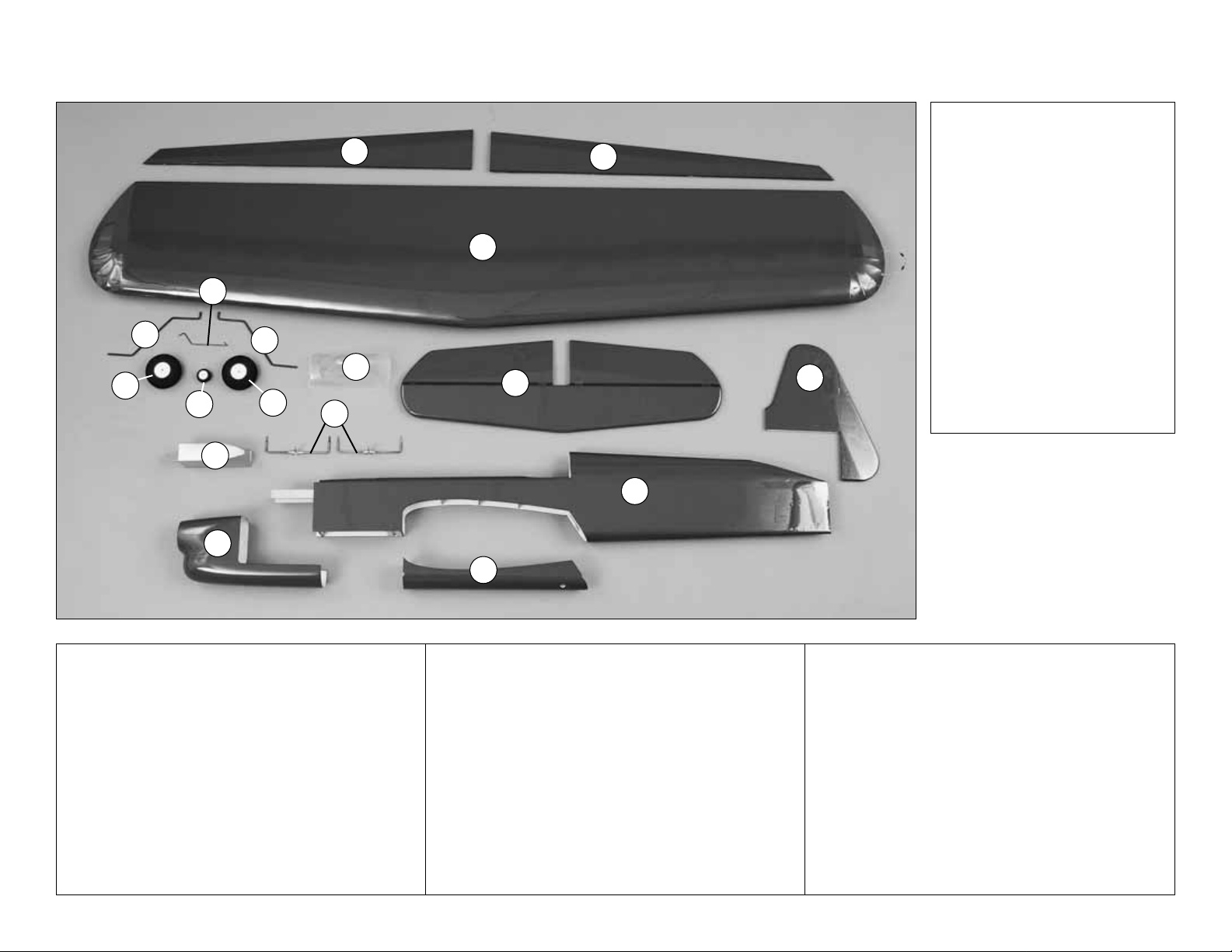
PARTS PHOTOGRAPHED
1. Flaps
2. Wing
3. Hor izontal Stabilizer with
Elevators
4. Fuselage
5. Belly Pan
6. Ver tical Stabilizer (Fin) with
Rudder
7. Fiberglass Cowl
8. Canopy
9. Main Landing Gear (2)
10. 2-1/2" [65mm] Main Wheels (2)
11. Tail Gear Wire
12. Tail Wheel
13. Fuel Tank
14. Joiner Wires (2)
PARTS NOT PHOTOGRAPHED
(2) 4-40 x 17-1/2" [445mm] Pushrods
(2) 4-40 Threaded Metal Clevises
(1) Non-threaded Metal Clevis
(2) 4-40 x 1-1/2" [38mm] Phillips Head Screws
(wing mounting)
(4) 4-40 x 1" [25mm] Socket Head Cap Screws
(engine mounting)
(6) 4-40 Blind Nuts (2-wing mounting, 4-engine
mounting)
(6) #4 Flat Washers (2-wing mounting, 4-engine
mounting)
(4) #4 Lock Washers (engine mounting)
(2) 4-40 Nuts (for pushrods)
(4) 1/8" [3mm] Wheel Collars (main wheels)
(1) 3/32" [2mm] Wheel Collar (tail wheel)
(5) 6-32 Set Screws (wheel collars)
(4) #2 x 1/2" [13mm] Screws (landing gear straps)
(6) #2 x 1/4" [6mm] Screws (cowl)
(2) Nylon Straps (main landing gear)
(14) Hinges
(3) Silicone Clevis Retainers
(1) Bellcrank w/leadouts (factory installed)
(1) 1/4" x 1/2" x 5" [6 x 12 x 130mm] Balsa Stick
(fuel tank mounting)
(1) 1" x 1-1/2" [26 x 38mm] Plywood Wing Bolt Plate
(1) Decal Sheet.
KIT CONTENTS
1
2
3
4
5
7
8
9
13
12
9
6
1
10
10
11
14
Page 6
IMPORTANT BUILDING NOTES
•
There are two types of screws used in this kit:
Sheet metal screws are designated by a number
and a length.
For example #6 x 3/4" long [19mm]
This is a number six screw that is 3/4" [19mm] long.
Machine screws are designated by a number,
threads per inch, and a length.
For example 4-40 x 3/4" long [19mm]
This is a number four screw that is 3/4" [19.1mm]
long with forty threads per inch
.
•
When you see the term
test fit
in the instructions,
it means that you should first position the part on
the assembly without using any glue, then
slightly modify or
custom fit
the part as necessar y
for the best fit.
•
Whenever the term
glue
is written you should rely
upon your experience to decide what type of glue
to use. When a specific type of adhesive works
best for that step, the instructions will tell y ou what
glue is recommended.
•
Whenever just
epoxy
is specified, you may use
either
30-minute (or 45-minute) epoxy
or
6-minute
epoxy. When 30-minute epoxy is specified, it is
highly recommended that you use only 30-minut e
(or 45-minute) epoxy because you will need the
working time and/or the additional strength.
•
Photos and sketches are placed before the
step they refer to .Frequently y ou can study photos in
following steps to get another view of the same parts.
ASSEMBLE THE WING
Hinge the Flaps
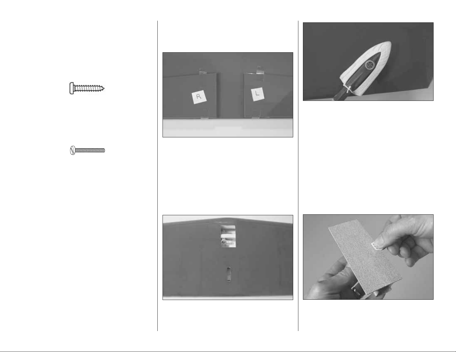
❏ 1. Mark the flaps as “right” and “left” before
removing them from the wing (the right flap is about
3/4" [20mm] shorter than the left flap).
❏ 2. Separate the flaps from the wing by peeling off
the tape.Any glue left from the tape can be removed
with naphtha lighter fluid or denatured alcohol.
❏3.Cut and remove the covering from the top of the
wing over the bellcrank opening and the pushrod
exit. Also cut the covering from the opening in the
bottom of the wing directly under the bellcrank screw .
❏ 4. Use a covering iron with a covering sock to
remove any wrinkles in the covering on the wing and
flaps. The best way is to glide the iron over the
covering until the wrinkles disappear, and then go
over the area again pushing down to bond the
covering to the wood. If the wrinkles don’t go away,
the balsa in that area may be bending inward. If this
is happening, do not press down on the iron in that
area. Simply let the heat of the iron shrink the
covering.If the wrinkles momentarily disappear, then
immediately reappear, the iron may be too hot, thus
causing air bubbles. Lower the temperature of the
iron or use a sharp #11 blade to puncture several
holes in the covering, then reheat. The suggested
iron temperature is around 360 degrees F.
❏ 5. Using a bar sander or a sanding block with
medium-grit sandpaper, remove any raised molding
imperfections and roughen the gluing surface of all
the hinges so glue will adhere.
- 6 -
Page 7
❏ 6. Test fit the hinges in the hinge slots in the wing
and flaps. If necessary, use a hobby knife or a small
razor saw blade to enlarge any hinge slots that are
too tight.
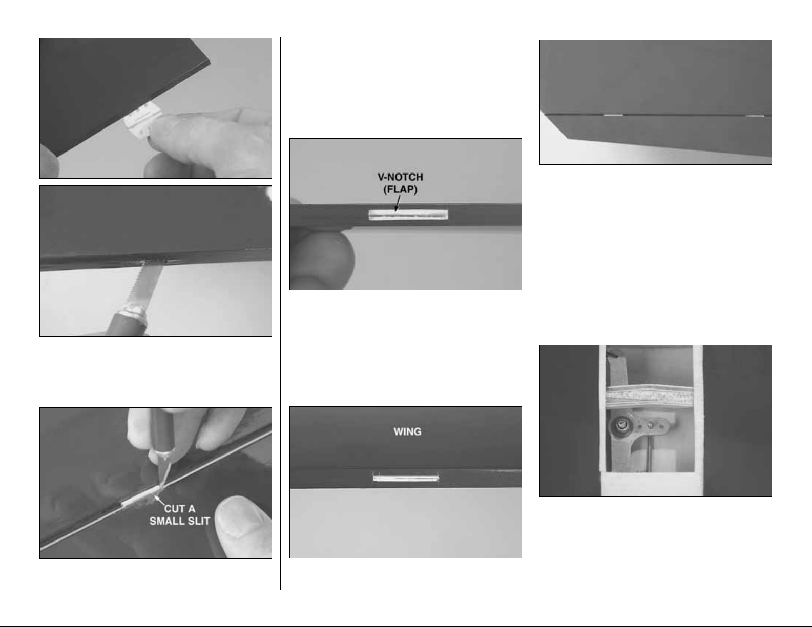
❏ 7. Without using any glue temporarily join both
flaps to the wing with eight hinges. Use a #11 hobby
blade to cut a small slit in the wing and flap on both
sides of all the hinges.These slits will mark the ends
of the hinge slots.
❏8.Remove the flaps from the wing and tak e out the
hinges.Cut a small “V-notch”between the slits cut in
the flaps only to accommodate the pin portion of the
hinges.This will allow the flaps to fit close to the
wing.
❏ 9. Cut a small str ip of covering between the slits
you cut over each hinge slot in the wing.
❏ 10. Without using any glue temporarily rejoin the
flaps to the wing with the hinges. There should be
little or no hinge gap and the flaps should move up
and down freely. Make adjustments where necessary
to close the hinge gaps.
Make the Flap Pushrod
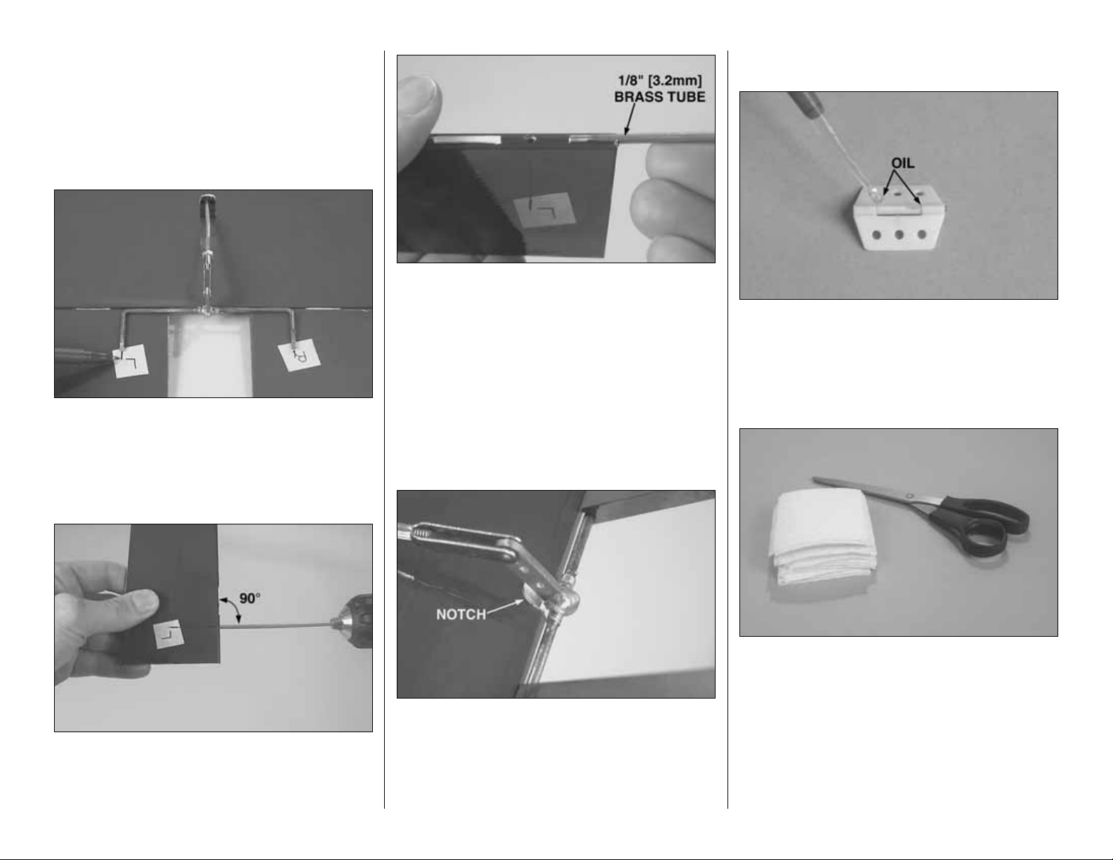
❏1.Bend and cut the flap pushrod as shown in the
full-size drawing on the back cover page from a 4-40
x 17-1/2" [445mm] threaded one-end pushrod.
Thread a 4-40 nut followed by a clevis onto the
pushrod.
❏2.Use a 7mm socket wrench or needle nose pliers
to loosen, but do not remove , the 4mm nut on the top
of the wing that secures the bellcrank.Guide the flap
pushrod through the exit slot in the top of the wing.
Then lift the bellcrank and fit the pushrod up through
the middle hole. Tighten the nut. Make sure the
pushrod and bellcrank operate freely.
- 7 -
Page 8
❏ 3. Test fit one of the metal clevises in the holes in
both control hornson both joiner wires. If the clevis
pins don’t go in, enlarge the holes in the joiner wires
with a 1/16" [1.6mm] drill. Clean the joiner
wires with
denatured alcohol, and then thoroughly
roughen them
with coarse sandpaper so epoxy will adhere.
❏ 4. Temporarily connect the clevis on the flap
pushrod to the top hole in the control horn on one of
the joiner wires. Position the joiner wire so the
pushrod is centered in the exit slot in the wing.Then
mark the location of the joiner wire onto the flaps.
❏ 5. Use a 1/8" [3.2mm] brass tube shar pened on
the end or a 1/8" [3.2mm] drill to drill holes into the
flaps in alignment with the marks that note the
location of the joiner wire.
❏ 6. Use a 1/8" [3.2mm] brass tube shar pened on
the end or a hobby knife to cut g rooves in the leading
edge of the flaps to accommodate the wire.
❏ 7. Test fit both flaps to the joiner wire. View the
trailing edges of the flaps from the end of the wing.
See if the flaps are parallel with each other (have the
same “up” and “down”). If necessary, “tweak” the
joiner wire to align the flaps.
❏ 8.Test fit the flaps to the wing with the joiner wire.
Cut a half-round notch in the trailing edge of the wing
to accommodate the solder joint and the control horn
during maximum flap deflection. Make certain
nothing interferes with full, smooth flap movement.
Make adjustments where necessary.
Join the Flaps to the Wing
❏ 1. Remove the flaps, hinges and joiner wire from
the wing. Carefully apply a small dab of petroleum
jelly or small drop of oil to the pivot points on the
hinges to keep epoxy from getting into the hinge joint
and jamming up the hinges.
❏ 2. Lay two or three paper towels on top of each
other.Cut the stack into small squares by cutting the
stack into four, equal-width strips. Cut the strips into
four equal squares. These paper towel squares will
come in handy throughout the building project (and
save you from wasting whole paper towels!).
One flap at a time will be glued to the wing…
- 8 -
Page 9

❏ 3. Mix a small batch of 30-minute epoxy. Use a
thin, metal ruler or something similar to force epoxy
into the hinge slots in one of the flaps and in the
hinge slots in the matching half of the wing. Proceed
immediately to the next step.
❏4.One at a time, lightly coat the top and bottom of
one half of four hinges with epoxy, then insert the
coated end of the hinges into the flap. Working
carefully not to get any epoxy into the hinge pins, use
small scraps of balsa or something similar to wipe off
excess epoxy as it is forced back out of the hinge
slots. Proceed immediately to the next step.
❏5.Use a piece of wire or a toothpick to apply epoxy
in the hole and groove in the flap for the joiner wire.
Coat the matching half of the control horn with epoxy,
and then insert it into the flap. Coat the other side of
hinges protruding from the flap with epoxy, and then
join the flap to the wing with the joiner wire. Wipe
away excess epoxy as it squeezes out.
❏ 6. Without using any glue, temporarily join the
other flap to the wing and the joiner wire. This will
align the joiner wire while the epoxy on the other side
is hardening. Do not disturb the wing until the epoxy
hardens.
❏ 7. After the epoxy on the first flap has hardened,
glue the other flap to the wing the same way. Allow
the epoxy on both flaps to fully harden for at least a
few hours before moving them. After the epoxy has
hardened, “break” the flaps free by rapidly moving
them up and down several times. Use a hobby knife
to pick any bits of epoxy from the hinge pins.
❏8.Adjust the clevis on the flap pushrod so the flaps
will be centered when the bellcrank is neutral. Slip a
silicone clevis retainer over the clevis, then connect
the clevis to the top hole in the control horn. Slip the
retainer over the clevis, and then tighten the 4-40 nut.
Finish the Wing
❏1.Cut the covering from the hole in the front of the
wing and glue in the wing dowel.
❏2. Cut the covering from the top and bottom of the
wing over the holes near the trailing edge for the
wing bolts.
Note: The Nobler includes bolts for mounting the
wing to the fuselage.However , the wing bolts are
intended for alignment and assembly only. Later,
the wing will be permanently glued to the
fuselage. If considering modifying your Nobler to
make the wing removable, keep in mind that
disengaging the elevator pushrod from the flap
control horn in order to remove the wing would
be cumbersome. Further, the Nobler has not
been flight tested with a removable wing.
- 9 -
Page 10

❏ 3. Remove the belly pan from the bottom of the
fuselage. Temporarily bolt the wing to the fuselage
with two 4-40 x 1-1/2" [38mm] screws and #4
washers. Trim the balsa cross brace as necessary
to accommodate the solder joint holding the control
horn to the flap joiner wire.
❏4.Place the belly pan on the bottom of the wing in
alignment with the fuselage. Tape the belly pan into
position. Use a fine-point felt-tip pen to mark the
outline of the belly pan onto the bottom of the wing.
Mark the fuselage sides on the top of the wing.
❏ 5. Remove the belly pan and wing. Use a shar p,
new knife blade or a heated soldering iron to cut the
covering from the wing 1/16" [2mm] inside the lines.
If using a knife, use a light touch and great care not
to cut into the sheeting under the covering or the
wing will be weakened. Using a soldering iron is
preferred because it melts through the covering
without cutting into the wood.Move the soldering iron
fast enough to melt through the covering without
burning the wood. After cutting the covering use
denatured alcohol and a tissue to clean the ink lines
from the covering.Then, peel off the covering.
❏ 6. Center the 1" x 1-1/2" [26 x 38mm] plywood
wing bolt plate over the holes on the bottom of the
wing. Glue the plate into position. Using the holes in
the top of the wing as a guide, drill 9/64" [3.6mm] (or
1/8" [3.2mm]) holes through the plate. Bolt the wing
onto the fuselage.
ASSEMBLE THE FUSELAGE
Prepare the Stab
❏ 1. Examine the stab and elevators and determine
which side looks best.Use a felt-tip pen to write “top”
on the side that looks best.
❏2. Separate the elevators from the stab by peeling
off the tape. Use a pin to poke three or four holes
along one side of all the “ribs” in the bottom of the
stab and elevators. These holes will allow expanded
air to escape while tightening the covering.
❏ 3. Use a covering iron to tighten the covering on
the stab and elevators.
❏4.The same as was done with the wing and flaps,
prepare the elevators and stab for the hinges by
enlarging the slots if necessary , test fitting the hinges
and cutting “V” notches in the elevators to
accommodate the hinge pins. Also prepare the
elevators for the joiner wire. Trim the trailing edge of
the stab as necessary to accommodate the solder
joint on the joiner wire. “Tweak” the joiner wire as
necessary to align the elevators with each other.
Refer to this photo for the following
two steps.
- 10 -
Page 11

❏ 5. Cut the covering from the fuselage over the
slots for the stab and fin.
❏ 6. Slide the stab into position. For now, center the
stab in the fuselage as best as you can by “eye.”
Stand approximately ten feet behind the model and
view the alignment of the stab and wing.If the stab is
not parallel with the wing, place a small weight on the
“high side” of the stab to bring it into alignment. If
weight is not enough, remove the stab from the
fuselage
and lightly trim or sand the stab saddle as necessary
until you can get the stab to align with the wing.
❏ 7. Now that the stab is level with the wing, center
the trailing edge of the stab in the fuselage by
measuring from both tips to the fuselage. Make sure
“X” = “X”on both sides of the stab as indicated in the
photo. Stick pins into the stab near the trailing edge
on both sides of the fuselage. This will keep the
trailing edge of the stab centered.
❏ 8. Insert a pin through the top, center of the
fuselage over the firewall. Tie a loop in one end of a
36" [1m] piece of non-elastic string such as
monofilament
or Ke vlar
line (K+SR4575).Slip the loop in the string over
the
T-pin.
❏ 9. Fold a piece of masking tape over the string
near the other end and draw an arrow on it.Slide the
tape along the string and align the arrow with one
end of the stab as shown in the photo. Swing the
string over to the other end of the stab and hold it in
the same position. Keeping the trailing edge of the
stab centered from side-to-side, move the stab tips
forward or back as necessary until the arrow aligns
with both ends of the stab.
❏10.The same as w as done for the wing, use a fine-
point felt-tip pen to mark the outline of the fuselage
all the way around both sides of the stab. Then, cut
and remove the covering from the center-section.
❏ 11. Cut the covering from the wing saddle 1/16"
[1mm] from the fuselage sides.
- 11 -
Page 12

Make the Elevator Pushrod
❏ 1. Make the elevator pushrod by cutting a 4-40 x
17-1/2" [445mm] threaded one-end pushrod to a
length of 13" [330mm]. Read the following
Hot Tip
about soldering. Then, solder a clevis onto the
un-threaded end of the pushrod (this will be the aft
end of the pushrod).
❏ 2. Thread a 4-40 nut and a clevis onto the
threaded end of the pushrod (this will be the front of
the pushrod and is the end that connects to the
control horn on the flap joiner wire). Slip a silicone
clevis retainer over both clevises on the pushrod.
❏ 3. Fit the elevator control horn into the slot in the
fuselage for the stabilizer. Then, guide the pushrod
down through the fuselage.Connect the clevis on the
pushrod to the middle hole in the flap control horn.
❏ 4. Bolt the wing to the fuselage. Working through
the cockpit, use hemostats or needle-nose pliers to
connect the clevis on the elevator pushrod to the
middle hole in the flap control horn.
❏5.Slide the stabilizer into the fuselage.Temporarily
join the elevators to the stab and joiner wire with the
hinges. Make certain the stab is pushed all the way
forward. The elevators must be centered when the
flaps are centered. If necessary, adjust the clevis on
the front of the elevator pushrod to center the
elevators with the flaps. This can be done by
disconnecting the clevis on the front of the pushrod,
removing the stab, and then feeding the pushrod
forward to access the clevis. Screw the clevis in or
out as necessary to lengthen or shorten the pushrod.
❏ 6. While the stab is in position and the pushrod is
connected, operate the flaps and elevators by pulling
on the leadouts.Make any adjustments necessary to
achieve smooth control movement. (When the
elevators move up, the flaps should move down.)
It’s best to install the fuel tank bef ore
permanently
mounting the wing, so let’s do that first.
Mount the Fuel Tank
❏ 1. Use epoxy thinned with denatured alcohol,
epoxy or fuelproof paint to fuelproof the fuel tank
compartment and the main landing gear rail.
This is what a properly soldered clevis looks like;
shiny solder with good flow, no blobs, flux
removed.
4. Immediately after the solder has solidified, but
while it is still hot, carefully use a cloth to quickly
wipe off the flux before it hardens. Important:
After the joint cools, coat with oil to prevent rust.
Note: Do not use the acid flux that comes with
silver solder for electrical soldering.
HOW T O SOLDER
1. Use denatured alcohol or other solvent to
thoroughly clean the pushrod. Use coarse
sandpaper to roughen the end of the pushrod
where it is to be soldered.
2. Apply a few drops of soldering flux to the end
of the pushrod, and then use a soldering iron or
a torch to heat it.“Tin” the heated area with silver
solder (GPMR8070) by applying the solder to
the end.The heat of the pushrod should melt the
solder–not the flame of the torch or soldering
iron–thus allowing the solder to flow. The end of
the wire should be coated with solder all the way
around.
3.Place the clevis on the end of the pushrod.Add
another drop of flux. Then, simultaneously heat
the clevis and pushrod.Slide the clevis the rest of
the way onto the pushrod as the solder melts.
Apply another small amount of solder while the
pushrod and clevis are still hot. The same as
before, the heat of the parts being soldered
should melt the solder, thus allowing it to flow.
Allow the joint to cool naturally without disturbing.
Avoid excess blobs, but make certain the joint is
thoroughly soldered.The solder should be shiny,
not rough.If necessary, reheat the joint and allow
to cool.
- 12 -
Page 13

❏2.Add a bead of RTV silicone to the bottom of the
engine mount rails where the fuel tank will contact
them, and then install the tank. Be certain the
narrower “wedge” portion of the tank faces the
outside of the circle (the right wing tip).
❏ 3. Cut two fuel tank rails from the 1/4" x 1/2" x 5"
[6 x 12 x 130mm] balsa stick to fit between the
fuselage sides below the tank. Apply a bead of RTV
silicone to the bottom of the rails. Glue them into the
fuselage securely, holding the tank in place.
…Now back to the wing.
Join the Wing & Stab to the Fuselage
❏ 1. Disconnect the elevator pushrod from the flap
and remove the wing and stab from the fuselage.
Now that the final length of the elevator pushrod has
been determined, tighten the 4-40 nut to the clevis
on the front of the pushrod.
❏ 2. Paint the cockpit and add any other details at
this time. The cockpit in the prototype was simply
painted black.
❏3.Mix up a batch of 30-minute epoxy. Apply epoxy
to the wing saddle on both sides of the fuselage and
to the wing where it contacts the fuselage. Install the
wing and bolt it into position. Use small balsa sticks
and/or your paper towel squares to wipe up excess
epoxy. Be cer tain none of the epoxy enters the flap
linkage. Allow the epoxy to fully harden before
proceeding.
❏ 4. Reconnect the elevator pushrod to the flap
control
horn (middle hole). Apply 30-minute epoxy to the
stab and fuselage where they join. Then, slide the
stabilizer into position.Use your paper towel squares
dampened with denatured alcohol to clean off any
excess epoxy.Then, confirm the stab alignment using
the
pin-and-string and by viewing the model from the
rear.
❏ 5. The same as was done with the flaps, apply a
few drops of oil or a dab of petroleum jelly to the
hinge pins on the elevator hinges. Use 30-minute
epoxy to permanently join one of the elevators to the
stab and the joiner wire with the hinges.Temporarily
join the other elevator to the other side of the stab.
Use a couple of rubber bands to close the hinge gap
by holding the elevator to the stab and clamp the
elevators together to k eep them aligned with each
other.
❏ 6. After the epoxy from the previous step has
hardened permanently, join the other elevator.
Join the Fin & Tail Wheel
❏
1. Mount the tail wheel to the prebent tail gear
wire with a small wheel collar and a 6-32 set screw.
Use Threadloc k er on the set scre w bef ore installing it
into the collar.
❏ 2. Cut the covering on the end of the fuselage
down the center.Peel bac k the cov ering, but don’t cut
any off.
❏ 3. Dr ill a 1/16" [1.6mm] hole and cut a groove in
the end of the fuselage for the tail gear wire.
❏ 4. Clean the tail gear wire with denatured alcohol
or other solvent. Roughen the wire so glue will
adhere. Glue the wire in the end of the fuselage with
30-minute epoxy.
Refer to this photo for the following
four steps.
Refer to this photo for the following
two steps.
- 13 -
Page 14

❏ 5. Using the same technique you used when
marking, cutting and removing the covering from the
wing and stabilizer, cut and remove the covering
from the fin where it will be glued to the fuselage.
❏ 6. Test fit the fin to be certain it fits well. Make
adjustments where necessary.
❏ 7. Glue the fin into position with 30-minute epoxy.
Use a builder’s triangle to make certain the fin is
perpendicular to the stabilizer.If necessary, masking
tape could be used to pull the fin to one side or the
other of the stab.Wipe away excess epoxy before it
hardens.
Mount the Main Landing Gear
❏
1. Use a small metal file to grind a flat spot near
the end of both prebent main landing gear wires.
❏2.Mount the wheels to the landing gear with a 1/8"
[3mm] wheel collar fastened by a 6-32 set screw on
both sides. Add a drop of oil to both sides of the
wheels so they spin freely.
❏3.Install the main landing gear wires in the landing
gear rail.Using the screw holes in the nylon straps as
a guide, drill 1/16" [1.6mm] holes through the landing
gear rail. Then, mount the gear with the straps and
four #2 x 1/2" [13mm] screws.
❏4.Use epoxy to glue the belly pan to the bottom of
the wing and fuselage.
Mount the Engine
❏1.Position the engine on the mounting rails so the
front of the drive washer (or the backplate of your
spinner) will be 3-5/8" to 3-3/4" [92 to 95mm] from
the firewall.With some engines (such as the O.S..40
LA) it may be necessary to slightly trim the lower,
inner edges of the mounting rails to accommodate
the engine. Note: The remote needle valve was
temporarily removed from the engine to facilitate
mounting and cowl installation.
❏2.Use a Great Planes Dead Center
™
Hole Locator
or a wire sharpened on the end to mark the engine
mounting rails for the mounting screws.
- 14 -
Page 15

❏ 3. Remove the engine. Drill 1/8" [3.2mm] holes at
the marks. Mount the engine to the mount with four
4-40 x 1" [25mm] SHCS (socket head cap screws),
#4 flat washers and lock washers and 4-40 b lind
nuts.
Mount the Cowl
❏
1.Use a high-speed rotary tool with a cutting bit to
cut slots in the aft end of the cowl to accommodate
the landing gear wires. Also cut an air inlet and air
exit hole. The exit hole may be combined with the
glow plug access hole.
❏ 2. Place the cowl on the fuselage and mount the
spinner and propeller.Align the cowl with the spinner.
There should be approximately 3/32" [2mm] between
the spinner and the cowl.
❏3.Holding the cowl in position, drill a 1/16"
[1.6mm]
hole through the cowl and fuselage for one of the
cowl mounting screws. The hole should be about
5/16" [8mm] from the aft edge of the cowl, placing it
about 1/4" behind the front edge of the fuselage side.
Screw in a #2 x 1/4" [6mm] screw just enough to hold
the cowl, but do not tighten the screw.
❏4.One at a time while holding the cowl in position,
drill a 1/16" [1.6mm] hole and insert a screw at the
remaining three marks. Also drill a hole through both
sides of the cowl and fuselage approximately 3/4"
[20mm] forward of the landing gear.
❏5.Remove the cowl.Enlarge the holes in the cowl
only with a 3/32" [2.4mm] drill. Test fit the cowl and
mount it to the fuselage with six #2 x 1/4" [6mm]
screws.
❏ 6. Remove the cowl screws and cowl. Add a
couple of drops of thin CA to the screw holes–don’t
add too much CA, or you will seal the holes.
❏7. Cut the holes in the cowl for the muffler screws.
This can be done by using a pencil to mark the
heads of the screws on the inside of the cowl, and
then removing the cowl and cutting the holes.
- 15 -
Page 16

❏ 8. Cut the hole for the muffler.Start by making the
hole small, and then enlarge it until the muffler can
be mounted.
❏ 9. Mount the needle valve and cut an access hole
for it in the cowl.Note: On the model featured in this
manual, the needle valve was mounted inverted. If
mounting the needle sideways (as the engine is
provided from the factory), a slot must be cut in the
cowl to accommodate the needle valve body.
❏ 10. Connect the fuel lines. The fuel tank included
with this kit uses a three-line system.As shown in the
sketch to the left, one line is the fuel pickup which
goes to the carburetor (or to the remote needle as in
the case of the O.S.LA engines).The other line goes
to the muffler for pressure (when the tank is full, fuel
will overflow through this line indicating that the tank
is full). The third line is used for filling the tank.This
line should be accessible from outside the fuselage
and is to be closed after fueling. A Great Planes
aluminum fuel line plug (GPMQ4166) was used to
close the fueling line. After the tank has been filled,
the fueling line can be tucked back inside the cowl.
- 16 -
Page 17

FINAL DETAILS
Mount the Canopy
❏ 1. Be certain that the flaps are centered when the
elevators are centered. Also be cer tain that all the
pushrods are connected and that the flaps and
elevator are operating smoothly. Make any
adjustments necessary.
❏ 2. Use scissors to cut out the canopy on the
molded-in cutlines. Start by cutting approximately
1/8" [3mm] from the lines. Then, do a final cut right
on the lines.
❏ 3. Mount the canopy to the fuselage with 1/4"
[6mm] white striping tape. Use 1/16" [2mm] white
striping tape to add the panel lines.
❏ 4. While you’ve got the 1/16" [2mm] striping tape
out, add the flap, elevator and rudder trim tab lines
as well.
Apply the Decals
1. Use scissors or a sharp hobby knife to cut the
decals from the decal sheet. Where possible, round
the corners so they are less likely to peel up during
cleaning and handling.
2. Be certain the model is clean. Prepare a dishpan
or small bucket with a mixture of liquid dish soap and
warm water–about 1/2 teaspoon of soap per gallon
of water.Submerse one of the decals in the solution
and peel off the paper backing. Note: Even though
the decals have a “sticky-back” and are not the water
transfer type, submersing them in soap & water
allows accurate positioning and reduces air bubbles
underneath.
3. Position the decal on the model where desired.
Holding the decal down, use a paper towel to wipe
away most of the water.
4. Use a piece of soft balsa or something similar to
squeegee remaining water from under the decal.
Apply the rest of the decals the same way.
GET THE MODEL READY TO FLY
Balance the Model (C.G.)
At this stage the model should be completely readyto-fly with all of the components installed including
the engine, muffler, propeller, spinner, landing gear
and wheels.
❏1.If using a Great Planes C.G.Machine to balance
the model, set the rulers to 2-1/2" [65mm]. If not
using a C.G. Machine, use a fine-point felt-tip pen or
More than any other factor, the C.G. (balance
point) can have the greatest effect on how a
model flies, and may determine whether or not
your first flight will be successful.If you value this
model and wish to enjoy it for many flights, DO
NOT OVERLOOK THISIMPORTANTPROCEDURE.
A model that is not properly balanced will be
unstable and possibly unflyable.
Do not permanently mount the canopy. If
adjustments are ever required to the pushrods,
the canopy may be removed to do so.
- 17 -
Page 18

1/8" wide tape to accurately mark the recommended
C.G. (center of gravity, or “balance point”) on the
bottom of the wing 2-1/2" [65mm] back from the
leading edge on both sides of the belly pan.
❏ 2. Place the model on a Great Planes CG
Machine, or lift it at the balance point you marked on
both sides of the fuselage. Note whether the nose or
tail drops. If the tail drops, the model is “tail heavy”
and weight must be added to the nose to balance.If,
however, the nose drops (as will likely be the case),
weight must be added to the tail to balance.
❏ 3. Add nose or tail weight to balance the model. If
nose weight is required it may be added by using a
“spinner weight” (GPMQ4645 for the 1 oz. [30g]
weight, or GPMQ4646 for the 2 oz. [55g] weight) or
Great Planes (GPMQ4485) “stick-on” lead which
may be added to the firewall (don’t attach weight to
the cowl–it is not intended to support weight). If tail
weight is required it may be placed on the right side
of the fuselage (opposite the muffler) under the
stabilizer. After the final amount of tail weight has
been determined (from several test flights) the
covering
may be cut from the lightening hole in the back of the
fuselage and the lead permanently glued inside.
Note: Do not rely upon the adhesive on the back of
the lead weight to permanently hold it in place. Over
time, fuel and exhaust residue may soften the
adhesive and cause the weight to fall off. Use #2
sheet metal screws, RTV silicone or epoxy to
permanently hold the weight in place.
❏ 4. IMPORTANT: If you found it necessary to add
any weight, recheck the C.G. after the weight has
been installed.
Wing Tip Weight
To begin, add 1 oz. [30g] of lead weight to the right
wing tip. This can be temporarily attached to the
bottom of the wing with the self-adhesive foam tape
attached to the weight. After the final amount of
weight required has been determined (after test
flying), it can be permanently attached inside the
wing tip with epoxy.
PREFLIGHT
Balance the Propellers
Carefully balance your propeller and spare
propellers before you fly. An unbalanced prop can be
the single most significant cause of vibration that can
damage your model. Not only will engine mounting
screws and bolts loosen, possibly with disastrous
effect, but vibration can also cause your fuel to foam,
which will, in turn, cause your engine to run hot or
quit.
We use a Top Flite Precision Magnetic Prop
Balancer™(TOPQ5700) in the workshop and keep a
Great Planes Fingertip Prop Balancer (GPMQ5000)
in our flight box.
Engine Check
If the engine is new,follow the engine manufacturer’ s
instructions to break-in the engine. After break-in,
confirm that the engine runs reliably and smoothly
and maintains full power–indefinitely. After you run
the engine on the model, inspect the model closely
to make sure all screws remained tight, the hinges
are secure and the prop is secure.
This is where the Nobler should balance for the
first flights–especially for sport flying and
beginning aerobatics. After the first few flights,
experienced modelers may wish to experiment
by shifting the C.G.
forward up to
1/4" [5mm]
or by
shifting the C.G. back, up to
1/4" [5mm] to
change
the flying
characteristics. If the C.G.is moved too
far forward (nose-heavy) response is slow and
the model becomes too difficult to flare for
landing. If the C.G. is moved too far aft (tailheavy) the model becomes too unstable and
over-responsive to control inputs. In any case,
start at the recommended balance point.
- 18 -
Page 19

Control Check
With the lines connected to the leadouts and your
assistant holding the model, operate the controls to
make sure they move smoothly. If any binding or
hesitation is detected, inspect the model and
eliminate the problem.
ENGINE SAFETY PRECAUTIONS
Keep all engine fuel in a safe place, away from high
heat, sparks or flames, as fuel is very flammable.Do
not smoke near the engine or fuel; and remember
that engine exhaust gives off a great deal of deadly
carbon monoxide.Therefore, do not run the engine
in a closed room or garage.
Get help from an experienced pilot when learning to
operate engines.
Use safety glasses when starting or running engines.
Do not run the engine in an area of loose gravel or
sand; the propeller may throw such material in your
face or eyes.
Keep your face and body as well as all spectators
away from the plane of rotation of the propeller as
you start and run the engine.
Keep these items aw a y from the prop:loose clothing,
shirt sleeves, ties, scarfs, long hair or loose objects
such as pencils or screwdrivers that may fall out of
shirt or jacket pockets into the prop.
Use a “chicken stick” or electric starter to star t the
engine. Do not use your fingers to flip the propeller.
Make certain the glow plug clip or connector is
secure so that it will not pop off or otherwise get into
the running propeller.
Make all engine adjustments from behind the rotating
propeller.
The engine gets hot! Do not touch it during or right
after operation. Make sure fuel lines are in good
condition so fuel will not leak onto a hot engine,
causing a fire.
To stop a glow engine, cut off the fuel supply by
closing off the fuel line or following the engine
manufacturer’ s recommendations .Do not use hands,
fingers or any other body part to try to stop the
engine.To stop a gasoline powered engine an on/off
switch should be connected to the engine coil.Do not
throw anything into the propeller of a running engine.
AMA SAFETY CODE (excerpt)
Read and abide by the following Academy of Model
Aeronautics Official Safety Code:
GENERAL
1.I will not fly my model aircraft in sanctioned events,
air shows, or model flying demonstrations until it has
been proven to be airworthy by having been
previously successfully flight tested.
3. Where established, I will abide by the safety rules
for the flying site I use, and I will not willfully and
deliberately fly my models in a careless, reckless
and/or dangerous manner.
5.I will not fly m y model unless it is identified with m y
name and address or AMA number, on or in the
model.
7. I will not operate models with pyrotechnics (any
device that explodes , b urns, or propels a projectile of
any kind).
8.I will not consume alcoholic beverages prior to, nor
during, participation in any model operations.
9.Children under 6 y ears old are only allowed on the
flight line as a pilot or while under flight instruction.
CONTROL LINE
1. I will subject my complete control system
(including safety thong, where applicable) to an
inspection and pull test prior to flying. Pull test will be
in accordance with the current Competition
Regulations for applicable model category. Models
not fitting a specific category as detailed shall use
those pull test requirements for Control Line
Precision Aerobatics.
2.I will assure that m y flying area is safely clear of all
utility wires or poles.
3.I will assure that m y flying area is safely clear of all
non-essential participants and spectators before
permitting my engine to be started.
4. I will not fly a model closer than 50 feet [15m] to
any electrical power line.
CHECK LIST
❏ 1. Make sure areas exposed to fuel or exhaust
residue have been fuelproofed (such as the
fuel tank compartment, the landing gear rail,
the back of the firewall and the front of the
wing belly pan).
❏ 2. Check the C .G.according to the
measurements
and procedure provided in the manual.
❏ 3.
Use thread-locking compound on the set
screws
in the wheel collars that hold on the wheels.
During the last few moments of preparation your
mind may be elsewhere anticipating the
excitement of the first flight.Because of this, you
may be more likely to overlook certain checks
and procedures that should be performed before
the model is flown.To help avoid this, a check list
is provided to make sure these important areas
are not overlooked. Many are covered in the
instruction manual, so where appropriate, refer
to the manual for complete instructions. Be sure
to check the items off as they are completed
(that’s why it’s called a
check list!
).
Failure to follow these safety precautions
may result in severe injury to yourself and
others.
- 19 -
Page 20

❏ 4. Add a drop of oil to the axles so the wheels will
turn freely.
❏ 5. Make sure all hinges are securely glued
in place.
❏ 6. Use thin CA to harden the holes in the
fuselage for the cowl mounting screws.
❏ 7. Confirm that the flaps and elevators operate
freely and smoothly by pulling on the leadouts.
❏ 8. Make sure the fuel lines are connected and
are not kinked.
❏ 9. Balance your propeller and spare propellers.
❏ 10. Tighten the propeller nut and spinner.
❏ 11. Place your name, address, AMA number and
telephone number on or inside your model.
❏ 12. If you wish to photograph your model, do so
before the first flight.
FLYING
Flying Precautions
Preflight
Note: The Top Flite Nobler ARF is not a beginner’s
model. It is intended for beginning to advanced stunt
pilots who have had some previous control line
experience. If you are an inexperienced pilot seek
the assistance of a knowledgeable control line pilot
who can help you with your first flights.
Beginning stunt pilots should make their first flights in
calm or low wind conditions. Stronger winds may
blow the model inward which will decrease line
tension resulting in loss of control.If the lines ever do
go slack, quickly step back to tighten the lines and
regain control. Of course, this is most likely to
happen, and should be expected, as the model
approaches the upwind half of the circle.
Place the model and starting equipment where the
wind will be behind the model when it is released for
takeoff.
For the first half-circle (during the brief period when
the pilot has the least control before the model is “up
to speed”) the wind will push the model outward to
maintain line tension.
Mark the center of the flying circle with paint, chalk or
a suitable object (such as a shop towel) so you won’t
wander.This is especially important if the flying area
is limited.
With your assistant holding the model, walk from the
model toward the handle in the center of the circle
while using your fingers to keep the lines separated.
This will ensure that the lines are not twisted and are
free to operate the controls.
Study these flying safety precautions before
flying the Nobler ARF.
1. Always inspect your equipment before each
flight. Make certain the lines, leadouts and
handle are in good condition. Make sure
there are no kinks in the lines.
2. Fly only in unobstructed areas free from
trees, shrubs and bushes, poles, stakes,
parking barriers and fences.
3. Be aware of any spectators that may wander
into the flying circle.If this is a possibility,
have
your assistant ready to perform crowd
control.
4. The model must NEVER be flown in the
vicinity of high-tension lines or any other
electrical lines.
5. Never fly when thunder storms or lightning
are present.
6. Take any precautions necessary to insure the
safety of spectators, the model and property.
7. Never touch the engine during or soon after
operation.
8. Keep clear of the rotating propeller and do
not let assistants or spectators get in the arc
of the propeller.
- 20 -
Page 21

While the pilot is holding the lines, the assistant
should walk the model once around the circle to be
certain the flight path is clear and to double-check
that
there are no obstructions that could snag the lines.
The pilot should double-check the operation of the
controls by pulling and pushing on the handle and
having the assistant signal what the controls are
doing (“up” and “down”).
Takeoff
Note: A fully cowled engine may run at a higher
temperature than an un-cowled engine. Therefore,
the fuel mixture should be richened so the engine
runs at least 200 RPM below peak speed.By running
the engine slightly rich, you will help prevent deadstick landings caused by overheating. Traditionally,
control line pilots intentionally set their engines rich
so that during vertical maneuvers, the engine will not
“over lean,” thus causing overheating. Further, full
RPM is usually not desired for stunt flying.
When both the pilot and assistant are ready, the
model may be fueled and started.Once the engine is
running and the model is ready to be released, the
assistant should point the nose of the model slightly
away from the circle .This will help keep the lines taut
for the first few feet until the model gets going.
Upon the pilot’s signal, the assistant may release the
model–never push the model forward as doing so
may result in a crash.
The pilot should be ready–especially during
takeoff–to
briefly step back to maintain line tension until the
model has gained enough air speed to achieve line
tension on its own. Allow the model to roll out and
gain enough speed to become airborne. When
enough speed has been gained the pilot may raise
his arm slightly giving “up” elevator command, thus
allowing the model to leave the ground.
Once the model has lifted, maintain a slow and
steady climb until a comfortable altitude has been
reached (usually between “ey e-lev el”and
approximately
ten feet in the air). The lines must remain taut
throughout the entire flight. If the lines ever do go
slack the pilot will not have control of the model.
During most situations the model’s factory built-in
features will allow it to maintain good line tension, but
on occasions when the wind blows the model inward
or the model becomes too slow the modeler must
anticipate or notice a decrease in “pull” and quickly
step backward to tighten the lines and regain control.
To climb, the pilot will slowly raise his arm. To
descend, the pilot will slowly lower his arm. To
maintain level flight the pilot will hold his arm
horizontally. Beginning pilots should control the
model by keeping their arm straight and bending at
the elbow with little or no wrist movement. Later,
- 21 -
Page 22

when they become more experienced, wrist
movement may be increased to increase control
response. All control inputs should be smooth.
Continue flying the model in a level attitude, getting
used to how the controls react and how the model
“feels.” Do this until the engine r uns out of fuel. With
a full tank of fuel the Nobler will fly for a little ov er f our
minutes, but actual flight time depends on several
factors, such as the engine size and brand, needle
valve setting, propeller size, fuel, atmospheric
conditions, etc.
Landing
When the engine starts to sputter and/or speed up,
this is an indication that the tank is nearly empty.
Continue to fly the model in a level attitude until the
engine finally quits.The same as any time the model
slows, the pilot should step back to keep the lines
taut and maintain control. Allow the model to
descend until it is about two feet off the ground.
When the model has lost nearly all flying speed and
is a foot or two from the ground the pilot should raise
his arm to keep the lines taut and apply full up
elevator, allowing the model to gently touch down.
After the model has come to a stop the assistant may
retrieve the model and return it to the starting area.
In doing so the lines should be kept taut so they do
not become twisted or entangled.
Clean the model using paper towels and household
cleaner to wipe off exhaust residue. Inspect the
model thoroughly, looking for loose fasteners and
signs of damage or fatigue.Also make sure the prop
has not been damaged. Perform any maintenance
necessary to prepare the model for the next flight.
At the end of the flying session any residual fuel
should be drained from the tank.
After you have become familiar with the way your
Nobler flies and you are ready to begin performing
stunts, seek the assistance of an experienced stunt
pilot before attempting to learn new maneuvers on
your own. Almost any control line stunt maneuvers
are started with the model downwind from the pilot,
i.e.wind on the pilots back. Consult the AMA Control
Line section for stunt maneuvers.
One final note about flying your model. Have a goal
or flight plan in mind for every flight. This can be
learning a new maneuver(s), improving a
maneuver(s) you already know, or lear ning how the
model behaves in certain conditions (such as when
testing different propellers or fuel). This is not
necessarily to improve your skills
(though it is never
a bad idea!)
, but more importantly so you do not
surprise yourself by impulsively attempting a
maneuver and suddenly finding that you’v e run out of
time, altitude or airspeed.Every maneuver should be
deliberate, not impulsive.For example , if y ou’ re going
to do a loop, check your altitude and mind the wind
direction.A flight plan greatly reduces the chances of
crashing your model just because of poor planning
and impulsive moves. Remember to think!
Have a ball, keep the lines taut and always fly in
a safe manner.
GOOD LUCK, GREAT FLYING, AND HAVE FUN!
O.S. Engines
®
.40 LA-S Control Line Engine with Muffler
(OSMG1440)
The O.S. 40 LA-S offers the proven power of LA
Series R/C sport engines – but is engineered for the
special requirements of control line flying, replacing
the carburetor with a venturi that keeps the engine
running at a constant speed. A remotely mounted
needle valve k eeps your hands saf ely distanced from
the spinning prop during adjustments. An O-ring
helps seal the needle against fuel and air leaks,
while heavy-duty webbing reinforces the blue-finish,
one-piece crankcase in high-stress areas. Includes
E-3030 muffler, muffler mounting screws, #A3 glow
plug, and 2-year warranty. Fuel with 10-20% nitro
and 18% oil content recommended.
- 22 -
Page 23

- 23 -
AMA STUNT MANEUVERS
Here are some of the AMA Stunt Maneuvers. Refer
to the AMA Rule Book for full descriptions.
Takeoff
Reverse Wingovers
Consecutive Inside Loops
Inverted Flight
Consecutive Outside Loops
Consecutive Inside Square Loops
Consecutive Outside Square Loops
Consecutive Inside Triangular Loops
Horizontal Eights
Page 24

FLAP PUSHROD
TEMPLATE
FLIGHT LOG
DATE COMMENTS
Started Constr uction
Finished Construction
First Flight
First Loop
First Inverted Flight
First Wingover
 Loading...