

Page 1
WARRANTY.....Top Flite Models guarantees this kit to be free of defects in both material and workmanship at the date of purchase. This warranty does
not cover any component parts damaged by use or modification. In no case shall Top Flite‘s liability exceed the original cost of the purchased kit. Fur ther, Top Flite reserves
the right to change or modify this warranty without notice.In that Top Flite has no control over the final assembly or material used for final assembly, no liability shall be assumed
nor accepted for any damage resulting from the use by the user of the final user-assemb led product. By the act of using the user-assembled product the user accepts all resulting
liability.If the buyer is not prepared to accept the liability associated with the use of this product,the buyer is advised to immediately return this kit in ne w and unused
condition to the place of purchase.
Top Flite Models P.O. Box 788 Urbana, Il 61803 Technical Assistance Call (217)398-8970 productsupport@top-flite.com
READ THROUGH THIS INSTRUCTION BOOK FIRST. IT CONTAINS IMPORTANT INSTRUCTIONS AND WARNINGS CONCERNING THE ASSEMBLY AND USE OF THIS MODEL.
TOPA1000 V1.0
Entire Contents © Copyright 2003
Wingspan: 41.5 in [1055mm]
Wing Area: 398 sq in [26 sq dm]
Weight: 24.3 oz [689g]
Wing Loading: 8.8 oz/sq ft [25 g/dm
2
]
Length: 27 in [685mm]
Engine: .25 - .40 cu in C/L engine
[4.1 - 6.5 cc]
.25 Control Line Sport ARF
Page 2
TABLE OF CONTENTS
INTRODUCTION . . . . . . . . . . . . . . . . . . . . . . . . 2
SAFETY PRECAUTIONS. . . . . . . . . . . . . . . . . . 2
ADDITIONAL ITEMS REQUIRED . . . . . . . . . . . 3
Building Supplies . . . . . . . . . . . . . . . . . . . . . 3
Optional Supplies & Tools. . . . . . . . . . . . . . . 3
IMPORTANT BUILDING NOTES . . . . . . . . . . . . 3
REPLACEMENT PARTS . . . . . . . . . . . . . . . . . . 3
KIT CONTENTS . . . . . . . . . . . . . . . . . . . . . . . . 4
ASSEMBLY . . . . . . . . . . . . . . . . . . . . . . . . . . . . 5
Prepare the Wing. . . . . . . . . . . . . . . . . . . . . 5
Mount the Engine and Fuel Tank . . . . . . . . . 5
Install the Landing Gear . . . . . . . . . . . . . . . . 6
Mount the Wing To the Fuselage . . . . . . . . . 6
Install the Horizontal Stab. . . . . . . . . . . . . . . 6
Install the Ver tical Fin . . . . . . . . . . . . . . . . . . 7
Mount the Canopy . . . . . . . . . . . . . . . . . . . . 8
PREPARE THE MODEL FOR FLYING . . . . . . . . 8
Set the Control Throws. . . . . . . . . . . . . . . . . 8
Balance the Model (C.G.). . . . . . . . . . . . . . . 8
Identify Your Model. . . . . . . . . . . . . . . . . . . . 8
Ground Inspection . . . . . . . . . . . . . . . . . . . . 8
AMA SAFETY CODE. . . . . . . . . . . . . . . . . . . . . 9
FIND A SAFE PLACE TO FLY . . . . . . . . . . . . . . 9
FLYING . . . . . . . . . . . . . . . . . . . . . . . . . . . . 9
INTRODUCTION
Thank you for purchasing the Top Flite Model’s Flite
Streak ARF. The Flite Streak is a lightweight, high-
performance model that can be used as a Stunt Trainer
or for Slow Combat. It is a classic model, a timeless
design that always dra ws a crowd of admirers where ver
it is flown. It is largely pre-built and requires only a
couple of hours to complete.We found the Flite Streak
ARF flew best with a .25 engine on 60 foot lines.We
hope you will enjoy your Flite Streak.
For the latest technical updates or manual
corrections to the Flite Streak, visit the web site listed
below and select the Top Flite Model’s Flite Streak
ARF. If there is new technical inf ormation or changes
to this model, a “tech notice” box will appear in the
upper left corner of the page.
http://www.top-flite.com/airplanes/index.html
1. Your Flite Streak should not be considered a toy,
but rather a sophisticated, working model that
functions very much like a full-size airplane.Although
the Flite Streak is a light weight model, just the same
as any model plane, it should still be flown with care.
Even while gliding at slow speeds, the Flite Streak
could possibly cause injury to yourself or spectators
and damage property.
2.You must assemble the Flite Streak according to
the instructions. Do not alter or modify the model,
as doing so may result in an unsafe or unflyable
model. In a few cases the instructions may differ
slightly from the photos. In those instances the
written instructions should be considered as correct.
3. You must take the time to build straight, true
and strong.
4. You must use control lines that are in first-class
condition.Do not use lines that are bent, frayed or knotted.
5. You must correctly install all components so that
the model operates correctly on the ground and in
the air.
6.You must check the operation of the model before
every flight to insure that all equipment is operating
and that the model has remained structurally sound.
Be sure to check control components often and
replace them if they show signs of wear or fatigue.
7. If you are not already an experienced pilot, you
should fly the model only with the help of a
competent, experienced pilot.
8. Do not fly near overhead power lines.
Remember: Take your time and follow the
instructions to end up with a well-built model
that is straight and true.
If you have not flown this type of model before, we
recommend that you get the assistance of an
experienced pilot in your club for your first flights. If
you’ re not a member of a club , y our local hob b y shop
has information about clubs in your area whose
membership includes experienced pilots.
NOTE: We, as the kit manufacturer, provide you
with a top quality kit and great instructions, but
ultimately the quality and flyability of your finished
model depends on how you build it;therefore, we
cannot in any way guarantee the performance of
your completed model, and no representations
are expressed or implied as to the performance or
safety of your completed model.
PRO TECT YOUR MODEL,
YOURSELF & OTHERS
FOLLO W THESE IMPORT ANT
SAFETY PRECAUTIONS
- 2 -
Page 3
In addition to joining a club, we strongly recommend
you join the AMA (Academy of Model Aeronautics).
AMA membership is required to fly at AMA
sanctioned clubs. There are over 2,500 AMA
chartered clubs across the country. Among other
benefits, the AMA provides insurance to its members
who fly at sanctioned sites and events. Additionally,
training programs and instructors are available at
AMA club sites to help you get started the right way.
Contact the AMA at the address or toll-free phone
number below:
Academy of Model Aeronautics
5151 East Memorial Drive
Muncie, IN 47302-9252
Tele. (800) 435-9262
Fax (765) 741-0057
Or via the Internet at: http://www.modelaircraft.org
ADDITIONAL ITEMS REQUIRED
❏ Engine, .25 to .40 (.25 recommended)
❏ Propeller
❏ Prop safety nut
❏ Fuel tubing (GPMQ4131)
❏ Control handle (SULP2866)
❏ Control lines, .015 x 60’ (SULP2632)
❏ Control lines combat, .018 x 60’ (SULP2635)
❏ Line connectors (SULP2948)
BUILDING SUPPLIES
In addition to common household tools and hobby
tools, here is the list of items used to build the Flite
Streak.
Great Planes Pro™ CA and epoxy glue
is recommended.
❏ 6-minute epoxy (GPMR6042)
❏ 1 oz. Medium CA (GPMR6008)
❏ Hobby knife (HCAR0105)
❏ #11 blades (5-pack, HCAR0211)
❏ Small Phillips screwdriver (#1)
❏ Drill Bits: 1/16” [1.6mm], 3/32” [2.4mm], 1/8” [3.2mm]
❏ Threadlocker (GPMR6060)
OPTIONAL SUPPLIES & TOOLS
❏ Sandpaper and sanding block
❏ Small T-pins (HCAR5100) or craft pins
❏ CA applicator tips (HCAR3780)
❏ CA debonder (GPMR6039)
❏ Mixing cups (GPMR8056)
❏ 36” metal ruler (HCAR0475)
❏ Rubbing alcohol (for epoxy clean up)
❏ Accu-Throw
™
Deflection Gauge (GPMR2405)
❏ CG Machine
™
(GPMR2400)
❏ Sealing Iron (TOPR2100)
❏ Dead Center
™
hole locator (GPMR8130)
❏ Hot Knife
™
(HCAR0770)
IMPORTANT BUILDING NOTES
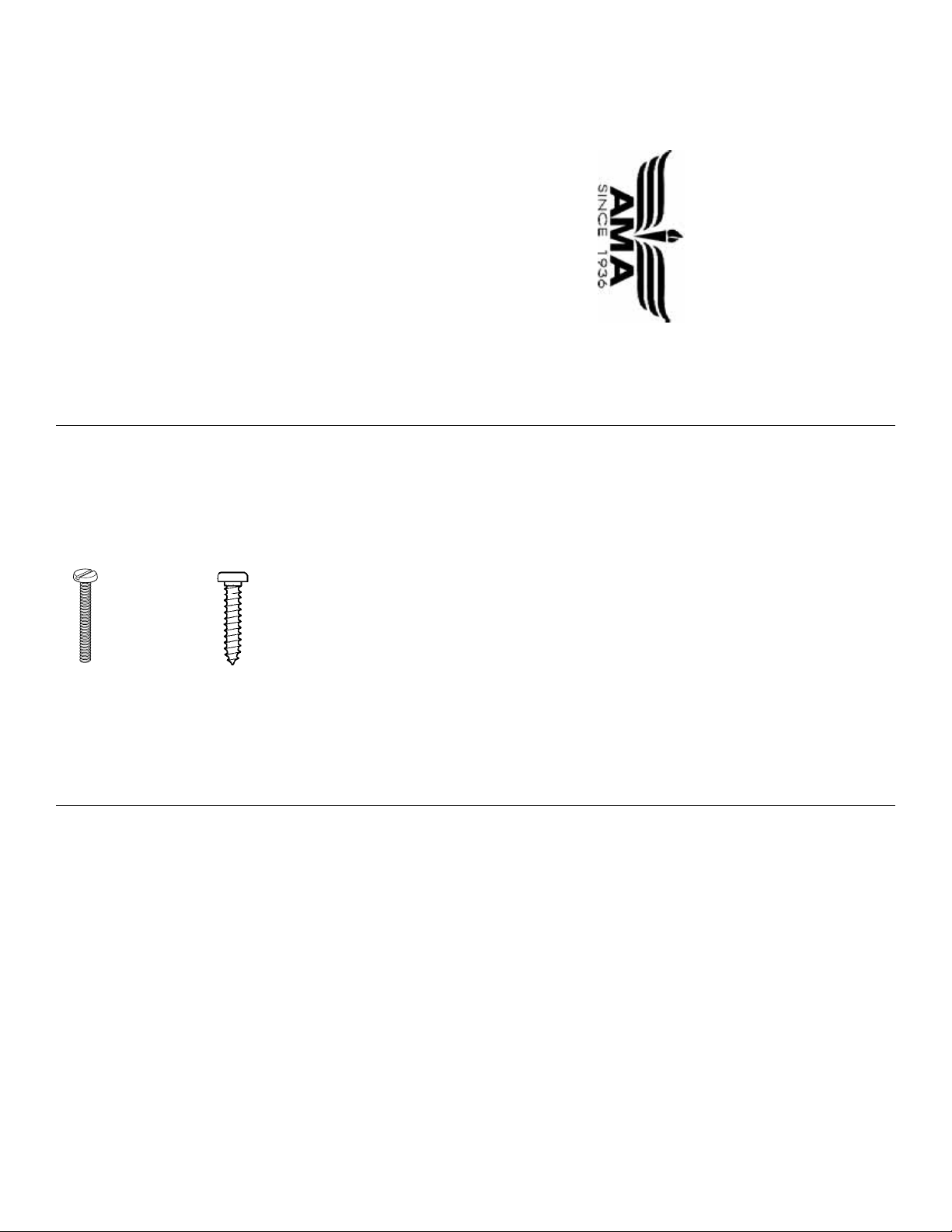
There are two types of screws used in this kit:
Sheet metal screws are designated by a number
and a length.
For example #6 x 3/4" long [19.1mm]
Machine screws are designated by a number,
threads per inch, and a length.
For example 4-40 x 3/4" long [19.1mm]
•
When you see the term
test fit
in the instructions,
it means that you should first position the part on
the assembly without using any glue, then
slightly modify or
custom fit
the part as necessar y
for the best fit.
•
When you get to each step, read that step
completely through to the end before you begin.
Frequently there is important information or a note
at the end of the step that you need to know before
you start.
•
Photos and sketches are placed before the step
they refer to. Frequently you can study photos in
following steps to get another view of the same parts.
•
The Flite Streak is factory-covered with Top Flite
MonoKote
®
film. Should repairs ever be required,
MonoKote can be patched with additional
MonoKote purchased separately. MonoKote is
packaged in six-foot rolls, but some hobby shops
also sell it by the foot. If only a small piece of
MonoKote is needed for a minor patch, perhaps a
fellow modeler would give you some. MonoKote is
applied with a model airplane covering iron, but in
an emergency a regular iron could be used. A roll
of MonoKote includes full instructions for
application. Following are the colors used on this
model and order numbers for six foot rolls.
White - TOPQ0204
Black - TOPQ0208
Red - TOPQ0201
REPLACEMENT PARTS
There are no replacement parts available for the Top
Flite Models Flite Streak ARF. If this kit is missing
parts, contact Top Flite Models Product Support.
(Please see Kit Contents)
- 3 -
Page 4
- 4 -
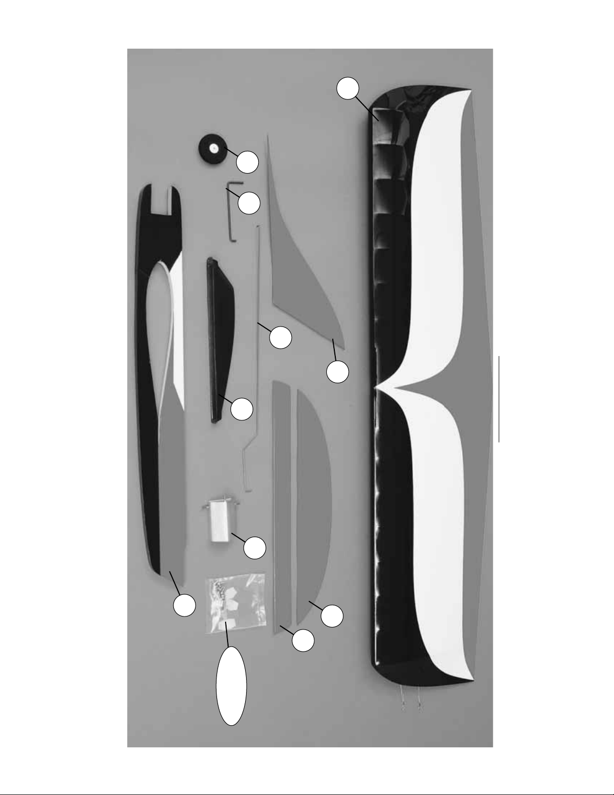
KIT CONTENTS
Before starting to build, use the Kit Contents list to take an inventory of this kit to make sure it is complete, and inspect parts to make sure they are of acceptable
quality .If any parts are missing or are not of acceptable quality , or if you need assistance with assemb ly, contact Top Flite Models Product Support.When reporting
defective or missing parts, use the part names exactly as they are written in the Kit Contents list on this page.
Top Flite Models Product Support • Telephone: (217) 398-8970 • Fax: (217) 398-7721
You can also check our web site at www.top-flite.com for the latest Flite Streak updates.
Kit Contents (Not Photographed)
(1) Nylon Control Horn (4) 4-40 x 1” Machine Screw (2) Set Screw
(1) Landing Gear Strap (4) #4 Lock Washer (3) Large Wood Screw
(2) Pushrod Retainer (8) #4 Flat Washer (4) Small Wood Screw
(4) CA Hinge (1) 90 Degree Metal Bracket (4) 4-40 Hex Nut
(2) 1/8” Wheel Collar (3) 2-56 x 1/2” Machine Screw
Kit Contents (Photographed)
1.Wing 6. Canopy
2. 1-3/4”Wheel 7. Fuel T ank w/bracket
3.Wire Landing Gear 8. Fuselage
4. Elevator Pushrod 9. Horizontal Stabilizer
5.Vertical Fin 10. Elevator
Hardware Bag
1
2
3
4
5
6
7
8
9
10
Hardware
Bag
Page 5

ASSEMBLY
Use a model covering iron to tightly shrink the
covering on the model as required. Be sure all
seams are tightly sealed.
Prepare the Wing
❏1.Loosen the screw that holds the bellcrank in place.
Insert the elevator pushrod into the middle hole in the
bellcrank as shown in the photo. Remove the screw,
then reinstall it with a drop of thread locker.
❏ 2. The ply bellcrank hatch is attached with two
small wood screws.Drill a 1/16” [1.6mm] pilot hole for
each screw. Enlarge the holes in the hatch with a
3/32”[2.4mm] drill bit. Mount the hatch with two small
wood screws.
Note: Only one side of the hatch is secured with
screws.The other end slides under the fuselage.
Mount the Engine and Tank
❏ 1. Position the engine on the fuselage and mark
the location of the mounting holes for the engine.The
Great Planes Dead Center hole locator (GPMR8130)
works well for this. Drill 1/8” [3.2mm] holes at the
marks. Mount the engine to the fuselage with four 4-
40 x 1" [25mm] machine screws, lock washers, flat
washers and hex nuts. The cutout for the engine is
sized for an O.S. .25 LA-S engine. If you are using a
different engine, you may need to adjust the cutout.
Note: Four extra flat washers are included and can
be used to establish some out-thrust on the engine
as in the above photo. Out-thrust will help increase
flying line tension.
Caution: Be sure you are mounting the engine on the
right side of the fuselage.The top of the fuselage has a
flat area on it for mounting the horizontal stabilizer .Note
also the white arrow shape in the covering on the top of
the fuselage just aft of the engine.
Note: An R/C engine can be used if the carburetor
arm is held in the full throttle position with some type
of linkage. (not supplied)
❏2.Make any needed adjustments to the vent tubes on
the fuel tank so they do not interfere with the engine.
❏3.Mount the fuel tank to the model using the supplied
strap and two large wood screws. Make sure that the
tank will clear the wing when it is installed.
❏ 4. Install the fuel line (not included) from the tank
to the engine.
- 5 -
Page 6

❏ 5. Mount the muffler onto the engine. Install the
pressure line from the muffler to the tank.The bottom
vent line on the tank can be used for filling and
draining the tank, but it should be plugged when the
engine is running.
Install the Landing Gear
❏ 1. Mount the landing gear wire to the model with
the Nylon Strap and two small wood screws.
❏ 2. Enlarge the hole in the wheel with a 1/8” [3.2mm]
drill bit.Mount the wheel to the landing gear wire with two
1/8” [3.2mm] Wheel Collars and two Set Screws.
Mount the Wing To the Fuselage
❏ 1. Use a tape measure to locate and mark the
exact centerline of the wing with a felt-tip pen. Draw
a line 1/4” [6.4mm] to the right of the centerline. (Do
not rely on the covering being exactly centered.)
❏ 2. Slide the wing into the fuselage. Align the right
side of the fuselage with the line that you drew 1/4”
[6.4mm] to the right of the centerline. Use a string or
tape measure to check the alignment of the wing.
The distance from the tail to the left and right wing
tips should be the same. Adjust the wing as needed.
Mark the sides of the fuselage on the top and bottom
of the wing with a felt-tip pen.
❏3. Remove the wing from the fuselage. Use a hobby
knife with a sharp #11 blade to cut and remove the
covering 1/16” [1.6mm] inside the lines marking the
fuselage sides.Be very careful not to cut into the balsa
under the covering as this will weaken the wing.
Note: The Hobbico Hot Knife
™
(HCAR0770), or a
soldering iron, works well for this as it allows cutting the
covering without cutting into the balsa.
❏ 4. Use a paper towel and alcohol to remove any
felt-tip pen marks.
❏ 5. Use medium CA or Epoxy to glue the wing to the
fuselage. If you use medium CA, align the fuselage
carefully first, then wick the CA into the joint.
Install the Horizontal Stab
❏ 1. Use a tape measure to locate and mark the
center of the trailing edge of the horizontal stabilizer.
Use a square or right triangle to mark the centerline
of the stab. Position the stab on the fuselage and
align it with the centerline. Use a string or tape
measure to check the alignment using the same
technique you did with the wing. Mark the outline of
the fuselage on the bottom of the stab.
❏ 2. Remove the stab from the fuselage. Use a
hobby knife with a sharp #11 blade to cut and
remove the covering 1/16” [1.6mm] inside the lines
marking the fuselage sides.Be very careful not to cut
into the balsa under the covering as this will weaken
the stab. Use a paper towel and alcohol to remove
any felt-tip pen marks.
- 6 -
Page 7

❏ 3. Position the stab on the fuselage and align it as
before. From the rear of the model, check that the
stab is parallel with the wing. If it is not, lightly sand
the stab mount on the fuselage as needed. When
you are satisfied with the alignment, glue the stab in
place with medium CA or epoxy.
❏ 4. Insert the four CA hinges in the precut slots in
the elevator .Trial fit the ele vator to the stab .Make any
adjustments needed to the hinge slots. When
satisfied with the fit, glue the hinges in place with
three drops of thin CA on the top and bottom of the
hinges. DO NOT use any CA accelerator.
❏5.Mount the 90-degree metal bracket to the fuselage
left side using a large wood screw.There is a pilot hole
already drilled in the fuselage at the correct location.Be
sure to insert the elevator pushrod into the bracket
before you mount it into position.
❏6.The nylon control horn is mounted to the bottom of
the elevator inline with the pushrod. Mark the location
of the mounting holes and drill 3/32” [2.4mm] holes.
Mount the control horn using the supplied 2-56 x 1/2”
[12.7mm] machine screws and nylon backplate.
❏ 7. Enlarge the holes in the control horn with a
3/32” [2.4mm] drill bit. Insert the elevator pushrod
into the second hole from the end. Use a plastic
retainer to hold the pushrod in place.
Install the Vertical Fin
❏ 1. Position the vertical fin on the fuselage and
horizontal stab. Note that the leading edge of the fin
is centered on the fuselage just aft of the canopy, but
the rear of the fin is off center to the right. This will
help increase the flying line tension. Mark the outline
of the fin on the fuselage and stab.
❏ 2. Trim the covering from the fuselage and stab
inside the lines.Remove any felt-tip pen marks.Glue
the vertical fin in place with epoxy. Be sure the fin is
perpendicular to the horizontal stab. After the epoxy
hardens, reinforce the joint as needed.
- 7 -
Page 8

Mount the Canopy
❏1. Cut the canopy to fit the fuselage.The canopy can
be held in place with epoxy or small wood screws.
❏ 2. If you would like to add a tailskid to your Flite
Streak this can be done with a wood or sheet metal
screw or with a nylon tailskid. The photo shows a
Great Planes Wing Tip Skid (GPMQ4445).
PREPARE THE MODEL FOR FLYING
Set the Control Throws
Use a Great Planes AccuThrow (or a ruler) to
accurately measure and set the control throw of the
elevator as indicated in the chart that follows.
To increase the control surface throw, move the
pushrod to a hole that is closer-in on the control horn
on the control surface, or mov e the pushrod to a hole
that is farther out on the bellcrank. To decrease the
control surface throw, do the opposite.
Balance the Model (C.G.)
The C.G. (center of gravity) must be checked when
the model is ready to fly. All components should be
installed with the fuel tank empty.
❏ 1. Use a felt-tip pen or narrow strips of tape to
mark the balance point on the bottom of the wing
3-1/4”[82.6mm] from the leading edge of the wing on
both sides of the fuselage.
❏2.Lift the model, right side up, at the balance point
you marked on the bottom of the wing. We use the
Great Planes CG Machine™. If the nose drops the
model is nose-heavy and you must add weight to the
tail. If the tail drops, the model is tail-heavy and you
must add weight to the nose.
❏ 3. If additional weight is required to balance the
model, use small pieces of Great Planes stick-on
weight (GPMQ4485). Our prototype model required
one ounce of weight on the tail.
❏ 4. After placing weight on the model where
necessary , rechec k the C .G.to confirm that it is correct.
❏ 5. Attach the weight with screws or glue securely
in place.
Identify Y our Model
No matter if you fly at an AMA sanctioned club site
or if you fly somewhere on your own, you should
always have your name, address, telephone number
and AMA number on or inside your model. It is
required at all AMA club flying sites and AMA
sanctioned flying events. Fill out one of the
identification tags on page 11 and place it on or
inside your model.
Ground Inspection
Before you fly you should perform one last overall
inspection to make sure the model is truly ready to fly
and that you haven’t o v erlooked anything.If you are not
thoroughly familiar with the operation of control line
models, ask an experienced modeler to perform the
inspection. Make certain the elevator is secure, the
pushrod is connected, the elevator responds in the
correct direction and the C.G.is correct.
IMPORTANT: More than any other factor, the
C.G. (balance point) can have the greatest effect
on how the model flies, and may determine
whether or not your first flight will be successful.If
you value this model, DO NOT OVERLOOK THIS
IMPORTANT PROCEDURE. A model that is not
properly balanced will be unstable and possibly
unable to fly correctly.
Set up the Flite Streak so it has the following
control surface throw:
ELEVATOR: 3/8” [10mm] up and down
Set the elevator throw as close to this setting as
possible. If you have too much control throw the
model may respond too quickly. If you do not have
enough throw, you may not be able to maneuver
the model or have enough control to land it.
- 8 -
Page 9

Be sure to conduct a pull test as specified by the
AMA for the type of use you intend to use the Flite
Streak for. When this manual was written, the
requirements were:
Combat - 35 lbs, 0.18” control lines
Aerobatics - 30 lbs, 0.15” control lines
AMA Safety Code (excerpts)
Read and abide by the following Academy of Model
Aeronautics Official Safety Code:
GENERAL
1.I will not fly my model aircraft in sanctioned events ,
air shows or model flying demonstrations until it has
been proven to be airworthy by having been
previously, successfully flight tested.
3.Where established, I will abide by the safety rules
for the flying site I use, and I will not willfully and
deliberately fly my models in a careless, reckless
and/or dangerous manner.
5. I will not fly my model unless it is identified with my
name and address or AMA number, on or in the model.
CONTROL LINE
1. I will subject my completed control system
(including safety thong, where applicable) to an
inspection and pull test prior to flying. Pull test will be
in accordance with the current Competition
Regulations for applicable model category. Models
not fitting a specific category as detailed shall use
those pull test requirements for Control Line
Precision Aerobatics.
2.I will assure that my flying area is safely clear of all
utility wires and poles.
3.I will assure that my flying area is safely clear of all
non-essential participants and spectators before
permitting my engine to be started.
4. I will not fly a model closer than 50 feet to any
electrical power line.
FIND A SAFE PLACE TO FLY
The best place to fly any model is at an AMA
chartered club field. Club fields are set up for C/L
flying, making your outing safer and more enjoyable.
We recommend that you join the AMA and a local
club so you can have a safe place to fly and have
insurance to cover you in case of a flying accident.
The AMA address and telephone number are in the
front of this manual.
If there is no club or C/L flying field in your area, find a
suitable site that is clear of trees, telephone poles, pow er
lines, buildings, busy streets and other obstacles.
In addition to obstacles, it is important to be aware of
people who may wander into the area once you
begin flying. At AMA club flying sites it is a severe
rule infraction to fly over others, and this is a good
practice if flying elsewhere. C/L models tend to
attract onlookers whose numbers can soon multiply,
forming small, uncontrolled crowds. Onlookers pose
two main problems. First is the danger of actually
crashing your model into a person, causing injury.
Second is the distraction while you are trying to
concentrate on flying. To minimize or avoid this
problem, have an assistant standing b y who can spot
people who wander into your flying site (so you can
avoid flying over them) and who can perform “crowd
control” if people start to gather.
FLYING
IMPORTANT: If you are an inexperienced modeler we
strongly urge you to seek the assistance of a
competent, experienced C/L pilot to check your model
for airworthiness AND to teach you how to fly.No matter
how stable or “forgiving” the Flite Streak is, attempting
to learn to fly on your own is dangerous and may result
in destruction of your model or even injury to yourself
and others. Therefore, find an instructor and fly only
under his or her guidance and supervision until you
have acquired the skills necessary for safe and fully
controlled operation of your model.
Takeoff
For your first flights we recommend flying the Flite
Streak when the wind is no greater than ten miles
per hour. Less experienced flyers should fly only in
light wind conditions. Frequently, winds are calm in
the early morning and early evening.Often these are
the most enjoyable times to fly anyway!
Where you place your model in the flying circle for
takeoff can be important.Do not takeoff directly into the
wind as this will place the model in a crosswind,
pushing the model into the circle, shortly after takeoff,
when the line tension is minimal. Takeoff should be
made with a quartering downwind/crosswind so that the
model reaches flying speed and full line tension as it
enters the headwind.
Be sure to confirm with your assistant the signal you
will use to have him launch the model. When ready
to launch, the assistant should hold the rear of the
fuselage while you check the ele vator response to be
sure you have the control handle oriented correctly.
Flight
The Flite Streak is a very responsive model. Be
prepared for this on your first flight. The main
purpose of the first few flights is to learn how the
model behaves and to adjust the elevator
responsiveness to suit your style of flying.You may
also want to adjust line tension by changing the
engine out-thrust angle or by adding weight to the
outside wing tip.
Best of luck and happy flying!
- 9 -
Page 10

- 10 -
O.S. Engines
®
.25 LA-S Control Line
Engine with Muffler (OSMG1425)
LA-S control line power plants replace the
carburetor with a venturi that keeps the
engine running at a constant speed. Other
features match those found on O.S. LA
engines for R/C planes: a remote needle
valve to reduce the chance of injury from
spinning props; a nylon backplate mount
and ratchet spring to help hold settings
against “creep” cause by vibration; and an
O-ring to seal the needle from fuel and air
leaks. The crankcase has a blue finish and
is reinforced in high-stress areas with
heavy-duty webbing. Includes #A3 glow
plug and 2-year warranty protection.
Hobbico
®
Hot-Shot
™
2 Glow Starters
With Sanyo
®
cell power!
•
Recharge overnight with included
wall adapter.
Hot-Shot 2 glo-starters combine a locking
glow plug clip designed for standard or
4-stroke plugs with a high-capacity Sanyo
rechargeable NiCd. The 2.3" Standard and
3.8" Long boast 1500mA of NiCd power. The
Super version delivers 4000mA — enough f or
an entire day of modeling. All three feature a
Twist-and-Lock Connector for safer, faster
starts and long-lasting dependability. Their
heavy-duty wall outlet adapter with LED
indicator lets you recharge the battery
overnight.One-year warranty.
HCAP2520 Hot-Shot 2 Standard
HCAP2522 Hot-Shot 2 Long
HCAP2528 Hot-Shot 2 Super
Hobbico
®
Ultra-Tote
™
Field Box Kit
(HCAP5020)
Keep your field gear organized and handy!
Hobbico’s easy-to-assemble Ultra-Tote kit
features sturdy, thick plywood panels, and
comes with drawer knob, screws, washers,
Velcro
®
, foam pads, nylon strips and step-
by-step instructions. In addition to a full-
length drawer with divided compartments,
the tote has adjustable foam-padded
cradles for safe model maintenance;
ventilated storage area for a 12V field
battery; and a shelf to hold a 1-gallon can or
plastic bottle of fuel. Measures 19” x 8” x
17”. Comes unpainted; decals not included.
90-day warranty.
Page 11

- 11 -
BUILDING NOTES
Kit Purchased Date: ______________________
Where Purchased: _______________________
Date Assembly Started: ___________________
Date Assembly Finished: __________________
Finished Weight:_________________________
Date of First Flight: _______________________
FLIGHT LOG
This model belongs to:
Name
AMA number
Phone number
City, State Zip
Address
This model belongs to:
Name
AMA number
Phone number
City, State Zip
Address
This model belongs to:
Name
AMA number
Phone number
City, State Zip
Address
Page 12

 Loading...