

Page 1
™
WARRANTY.....Top Flite Models guarantees this kit to be free
from defects in both material and workmanship at the date of purchase. This warranty
does not cover any component parts damaged by use or modifi cation. In no case shall
Top Flite’s liability exceed the original cost of the purchased kit. Further, Top Flite
reserves the right to change or modify this warranty without notice.
In that Top Flite has no control over the fi nal assembly or material used for fi nal
assembly, no liability shall be assumed nor accepted for any damage resulting from
the use by the user of the fi nal user-assembled product. By the act of using the userassembled product, the user accepts all resulting liability.
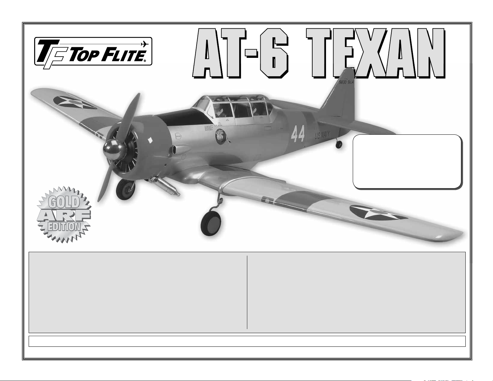
Wingspan: 69 in [1755mm]
Wing Area: 730 sq in [47.1 dm2]
Weight: 8.5-9.5 lb [3855-4310g]
Wing Loading: 27-30 oz/sq ft [82-91 g/dm2]
Length: 51 in [1295mm]
Radio: 6 channel w/8 servos
Engine: .60 cu in [10cc] two-stroke,
.70-.91 cu in [11.5-15cc] four-stroke
If the buyer is not prepared to accept the liability associated with the use of this
product, the buyer is advised to return this kit immediately in new and unused
condition to the place of purchase.
To make a warranty claim send the defective
part or item to Hobby Services at the address:
Hobby Services
3002 N. Apollo Dr. Suite 1
Champaign IL 61822 USA
Include a letter stating your name, return shipping address, as much contact information
as possible (daytime telephone number, fax number, e-mail address), a detailed
description of the problem and a photocopy of the purchase receipt. Upon receipt of
the package the problem will be evaluated as quickly as possible.
READ THROUGH THIS MANUAL BEFORE STARTING CONSTRUCTION. IT CONTAINS IMPORTANT INSTRUCTIONS AND WARNINGS CONCERNING THE ASSEMBLY AND USE OF THIS MODEL.
Top Flite Models Champaign, IL Telephone (217) 398-8970, Ext. 5 airsupport@top-fl ite.com
Entire Contents © Copyright 2008 TOPA0965Mnl V1.0
Page 2
TABLE OF CONTENTS
INTRODUCTION ..................................................... 2
SAFETY PRECAUTIONS .......................................2
DECISIONS YOU MUST MAKE .............................. 3
Radio Equipment .................................................. 3
Engine Recommendations ...................................3
ADDITIONAL ITEMS REQUIRED ..........................3
Adhesives and Building Supplies ..........................3
Optional Supplies and Tools .................................4
IMPORTANT BUILDING NOTES ............................ 4
KIT CONTENTS ...................................................... 4
ORDERING REPLACEMENT PARTS .................... 5
PREPARATIONS ..................................................... 6
ASSEMBLE THE WING .......................................... 6
Install the Flaps/Ailerons ......................................6
Install the Aileron/Flap Servos and Pushrods ....... 8
Install the Wing Joiners & Join the Wing Halves.. 10
Install the Retract Landing Gear and Wheels ..... 13
BUILD THE FUSELAGE .......................................15
Install the Stabilizers, Elevators and Rudder ...... 15
Install the Engine Fuel Tank & Throttle Servo ..... 18
Install the Radio System ..................................... 20
Final Set-up of the Retract Servo ....................... 21
Install the Cowl & Dummy Engine ...................... 22
Install the Cockpit & Remaining Scale Details .... 24
Apply the Decals ................................................. 26
GET THE MODEL READY TO FLY ....................... 27
Check the Control Directions .............................. 27
Set the Control Throws ....................................... 27
Balance the Model (C.G.) ................................... 28
Balance the Model Laterally ............................... 29
PREFLIGHT .......................................................... 29
Identify Your Model ............................................. 29
Charge the Batteries ........................................... 29
Balance Propellers .............................................29
Ground Check ..................................................... 29
Range Check ......................................................29
ENGINE SAFETY PRECAUTIONS .......................30
AMA SAFETY CODE ............................................ 30
CHECK LIST ......................................................... 30
FLYING .................................................................. 31
Fuel Mixture Adjustment ..................................... 31
Takeoff ................................................................31
Flight .....................................................Back Cover
Landing .................................................Back Cover
INTRODUCTION
The real lineage of the AT-6 Texan began in 1937
with a USAAF competition to develop a basic trainer.
The requirements were for a type capable of basic
instruction as well as simulating the controls and feel
of an actual combat aircraft. Top Flite has returned
this vintage airplane to the modeling community in
the form of a “World Class” ARF that we are sure will
bring you hours of great fun.
For the latest technical updates or manual corrections
to the AT-6 Texan visit the Top Flite web site at www.
top-fl ite.com. Open the “Airplanes” link, and then
select the AT-6 Texan ARF. If there is new technical
information or changes to this model a “tech notice”
box will appear in the upper left corner of the page.
ACADEMY OF MODEL AERONAUTICS
If you are not already a member of the AMA, please
join! The AMA is the governing body of model
aviation and membership provides liability insurance
coverage, protects modelers’ rights and interests and
is required to fl y at most R/C sites.
Academy of Model Aeronautics
5151 East Memorial Drive
Muncie, IN 47302-9252
Tele. (800) 435-9262
Fax (765) 741-0057
www.modelaircraft.org
IMPORTANT!!! Two of the most important things you
can do to preserve the radio controlled aircraft hobby
are to avoid fl ying near full-scale aircraft and avoid
fl ying near or over groups of people.
SCALE COMPETITION
Though the Top Flite AT-6 is an ARF and may not have
the same level of detail as an “all-out” scratch-built
competition model, it is a scale model nonetheless
2
and is therefore eligible to compete in the Fun Scale
class in AMA competition (we receive many favorable
reports of Top Flite ARFs in scale competition!). In Fun
Scale, the “builder of the model” rule does not apply.
To receive the fi ve points for scale documentation, the
only proof required that a full size aircraft of this type in
this paint/markings scheme did exist is a single sheet
such as a kit box cover from a plastic model, a photo, or
a profi le painting, etc. If the photo is in black and white
other written documentation of color must be provided.
Contact the AMA for a rule book with full details.
If you would like photos of full-size AT-6s for scale
documentation, or if you would like to study the
photos to add more scale details, photo packs are
available from:
Bob’s Aircraft Documentation
3114 Yukon Ave
Costa Mesa, CA 92626
Telephone: (714) 979-8058
Fax: (714) 979-7279
www.bobsairdoc.com
PROTECT YOUR MODEL, YOURSELF AND
OTHERS. FOLLOW THESE IMPORTANT
SAFETY PRECAUTIONS
1. Your AT-6 should not be considered a toy, but
rather a sophisticated, working model that functions
very much like a full-size airplane. Because of its
performance capabilities, the AT-6, if not assembled
and operated correctly, could possibly cause injury to
yourself or spectators and damage to property.
2. You must assemble the model according to the
instructions. Do not alter or modify the model, as
doing so may result in an unsafe or unfl yable model.
In a few cases the instructions may differ slightly from
the photos. In those instances the written instructions
should be considered as correct.
3. You must take time to build straight, true
and strong.
Page 3
4. You must use an R/C radio system that is in fi rstclass condition, and a correctly sized engine and
components (fuel tank, wheels, etc.) throughout the
building process.
5. You must correctly install all R/C and other
components so that the model operates correctly on
the ground and in the air.
6. You must check the operation of the model before
every fl ight to insure that all equipment is operating
and that the model has remained structurally sound. Be
sure to check clevises or other connectors often and
replace them if they show any signs of wear or fatigue.
7. If you are not an experienced pilot or have not
fl own this type of model before, we recommend that
you get the assistance of an experienced pilot in your
R/C club for your fi rst fl ights. If you’re not a member
of a club, your local hobby shop has information
about clubs in your area whose membership includes
experienced pilots.
8. While this kit has been fl ight tested to exceed
normal use, if the plane will be used for extremely
high stress fl ying, such as racing, or if an engine
larger than one in the recommended range is used,
the modeler is responsible for taking steps to reinforce
the high stress points and/or substituting hardware
more suitable for the increased stress.
We, as the kit manufacturer, provide you with a top
quality, thoroughly tested kit and instructions, but
ultimately the quality and fl yability of your fi nished
model depends on how you build it; therefore, we
cannot in any way guarantee the performance of
your completed model, and no representations
are expressed or implied as to the performance or
safety of your completed model.
Remember: Take your time and follow the
instructions to end up with a well-built model that
is straight and true.
DECISIONS YOU MUST MAKE
This is a partial list of items required to fi nish the
AT-6 that may require planning or decision making
before starting to build. Order numbers are provided
in parentheses.
RADIO EQUIPMENT
ADDITIONAL ITEMS REQUIRED
ADHESIVES AND BUILDING SUPPLIES
This is the list of Adhesives and Building Supplies
that are required to fi nish the AT-6.
❏ 1/2 oz. [15g] Thin Pro
❏ 1 oz. [30g] Medium Pro CA+ (GPMR6008)
❏ Pro 30-minute epoxy (GPMR6047)
❏ Pro 6-minute epoxy (GPMR6045)
❏ R/C foam rubber (1/4" [6mm] - HCAQ1000
❏ 3’ [900mm] standard silicone fuel tubing
(GPMQ4131)
❏ Dr ill bits: 1/16" [1.6mm], 5/64" [2mm], 3/32" [2.4mm],
7/64" [2.8mm], 1/8" [3.2mm], 9/64" [3.6mm].
❏ 8-32 tap and drill set (GPMR8103)
❏ Small T-pins (100, HCAR5100)
❏ #1 Hobby knife (HCAR0105)
❏ #11 blades (5-pack, HCAR0211)
❏ Stick-on segmented lead weights (GPMQ4485)
st
❏ 21
Century® sealing iron (COVR2700)
❏ 4 oz. [113g] aerosol CA activator (GPMR634)
❏ CA applicator tips (HCAR3780)
❏ Epoxy brushes (6, GPMR8060)
❏ Mixing sticks (50, GPMR8055)
❏ Mixing cups (GPMR8056)
❏ Microballoons (TOPR1090)
❏ Threadlocker thread locking cement (GPMR6060)
❏ Denatured alcohol (for epoxy clean up)
™
CA (GPMR6001)
9. WARNING: The cowl and air scoops included in
this kit are made of fi berglass, the fi bers of which
may cause eye, skin and respiratory tract irritation.
Never blow into a part to remove fi berglass dust, as
the dust will blow back into your eyes. Always wear
safety goggles, a particle mask and rubber gloves
when grinding, drilling and sanding fi berglass parts.
Vacuum the parts and the work area thoroughly after
working with fi berglass parts.
❏ 6-channel with seven servos of at least 50 oz-in.
and one retract servo of at least 60 oz-in.
❏ One 6" [150mm] servo extension (HCAM2701 for
Futaba)
❏ Seven 12" [300mm] servo extension (HCAM2711
for Futaba)
❏ Two Y-harnesses (HCAM2751 for Futaba)
❏ 1000 mAh battery (minimum)
ENGINE RECOMMENDATIONS
The recommended engine for the AT-6 is an O.S.® .60
two-stroke or .91 four-stroke.
3
Page 4
OPTIONAL SUPPLIES AND TOOLS
Here is a list of optional tools mentioned in the manual
that will help you build the AT-6.
❏ Masking tape (TOPR8018)
❏ Panel Line Pen (TOPQ2510)
❏ Rotary tool such as Dremel
®
❏ Rotary tool reinforced cut-off wheel (GPMR8020)
❏ Servo horn drill (HCAR0698)
❏ Hobby Heat
❏ AccuThrow
™
micro torch (HCAR0750)
™
Defl ection Gauge (GPMR2405)
❏ Precision Magnetic Prop Balancer (TOPQ5700)
❏ CG Machine
❏ Dead Center
Locator (GPMR8130)
™
(GPMR2400)
™
Engine Mount Hole
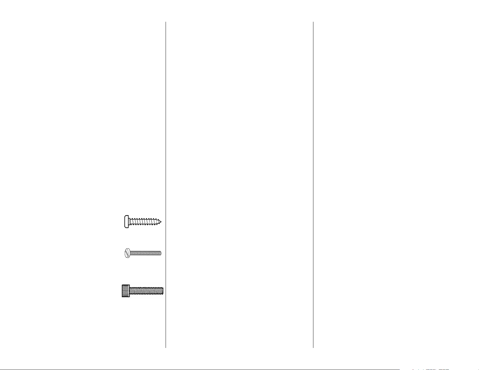
IMPORTANT BUILDING NOTES
• There are two types of screws used in this kit:
Sheet metal screws are designated
by a number and a length. For
example #6 x 3/4" [19mm]
Machine screws are designated
by a number, threads per inch,
and a length. For example 4-40 x
3/4" [19mm]
Socket Head Cap Screws (SHCS)
are designated by a number,
threads per inch, and a length. For
example, 4-40 x 3/4" [19mm]
• When you see the term test fi t in the instructions,
it means that you should fi rst position the part on
the assembly without using any glue, then slightly
modify or custom fi t the part as necessary for the
best fi t.
• Whenever the term glue is written you should rely upon
your experience to decide what type of glue to use.
When a specifi c type of adhesive works best for that
step, the instructions will make a recommendation.
• Whenever just epoxy is specifi ed you may use
either 30-minute (or 45-minute) epoxy or 6-minute
epoxy. When 30-minute epoxy is specifi ed it is
highly recommended that you use only 30-minute
(or 45-minute) epoxy, because you will need the
working time and/or the additional strength.
• Photos and sketches are placed before the step they
refer to. Frequently you can study photos in following
steps to get another view of the same parts.
• The AT-6 is factory-covered with Top Flite MonoKote®
fi lm. Should repairs ever be required, MonoKote can
be patched with additional MonoKote purchased
separately. MonoKote is packaged in six-foot rolls,
but some hobby shops also sell it by the foot. If only a
small piece of MonoKote is needed for a minor patch,
perhaps a fellow modeler would give you some.
MonoKote is applied with a model airplane covering
iron, but in an emergency a regular iron could be
used. A roll of MonoKote includes full instructions
for application. Following are the colors used on this
model and order numbers for six foot rolls.
Aluminum (TOPQ0205)
Black (TOPQ0208)
Cub Yellow (TOPQ0220)
Missile Red (TOPQ0201)
4
KIT INSPECTION
Before starting to build, inspect the parts to make
sure they are of acceptable quality. If any parts are
missing or are not of acceptable quality, or if you
need assistance with assembly, contact Product
Support. When reporting defective or missing parts,
use the part names exactly as they are written in the
Kit Contents list on this page.
Top Flite Product Support:
3002 N Apollo Drive Suite 1
Champaign, IL 61822
Telephone: (217) 398-8970
Fax: (217) 398-7721
E-mail: airsupport@top-fl ite.com
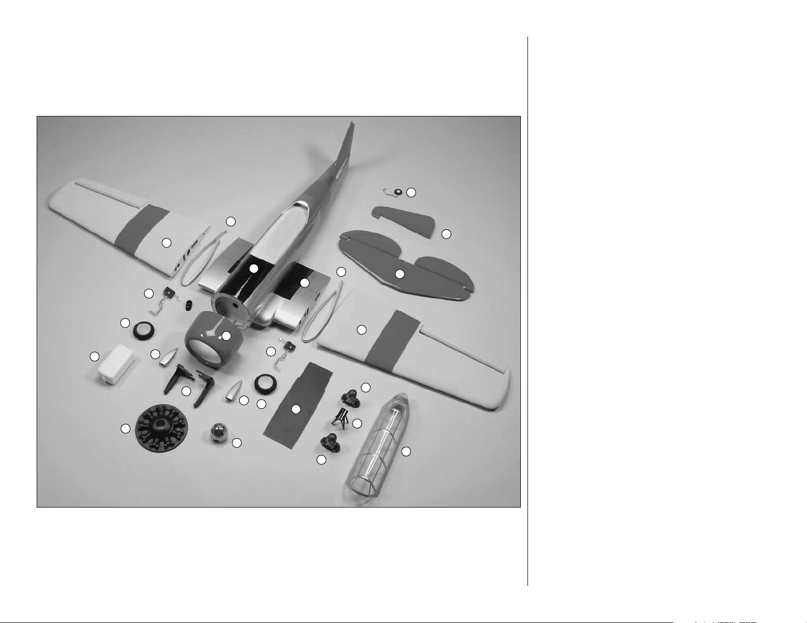
KIT CONTENTS
1. Right wing with aileron and fl ap
2. Left wing with aileron and fl ap
3. Joiner covers (2)
4. Horizontal stabilizer with elevators
5. Rudder
6. Tail wheel assembly
7. Fuselage
8. Wing center section with fl aps
9. Cowl
10. Main wheels (2)
11. Main retract assembly (2)
12. Fiberglass exhaust stack
13. Fuel tank
14. Engine mount halves (R&L)
15. Fiberglass dummy engine
16. Spinner
17. Cockpit fl oor
18. Fiberglass air scoops (2)
19. Pilots (2)
20. Turnover post
21. Canopy
Page 5
ORDERING REPLACEMENT PARTS
To order replacement parts for the Top Flite AT-6 ARF,
use the order numbers in the Replacement Parts
List that follows. Replacement parts are available
only as listed. Not all parts are available separately
(an aileron cannot be purchased separately, but is
only available with the wing kit). Replacement parts
are not available from Product Support, but can be
purchased from hobby shops or mail order/Internet
order fi rms. Hardware items (screws, nuts, bolts)
are also available from these outlets. If you need
6
3
5
1
assistance locating a dealer to purchase parts, visit
www.top-fl ite.com and click on “Where to Buy.” If
this kit is missing parts, contact Product Support.
REPLACEMENT PARTS LIST
7
8
11
10
9
13
18
11
3
2
4
Order Number Description How to purchase
Missing Pieces .................. Contact Product Support
Instruction Manual ............ Contact Product Support
Full-Size Plans .....................................Not Available
Contact your hobby supplier to purchase these items:
TOPA1740 ....... Wing
TOPA1741 ....... Fuselage
TOPA1742 ....... Tail Surface Set
14
15
18
10
16
17
19
19
20
21
TOPA1743 ....... Canopy
TOPA1744 ....... Cowl
TOPA1745 ....... Dummy Radial Engine
GPMQ9117 ...... Pilot
TOPA1746 ....... Decals
TOPA1747 ....... Spinner
TOPA1748 ....... Wire Landing Gear Set
TOPA1749 ....... Cockpit Kit
TOPA1750 ....... Wheels
TOPQ7950 ......Retracts w/o Wires
TOPA1751 ....... Fiberglass Scoop/Exhaust Set (3 pc.)
5
Page 6
PREPARATION
ASSEMBLE THE WING
❏ 1. If you have not done so already, remove the
major parts of the kit from the box and inspect for
damage. If any parts are damaged or missing, contact
Product Support at the address or telephone number
listed in the “Kit Inspection” section on page 4.
❏ 2. Remove the tape and separate the ailerons and
fl aps from the wing and the elevators from the stab.
Use a covering iron with a covering sock on high heat
to tighten the covering if necessary. Apply pressure
over sheeted areas to thoroughly bond the covering
to the wood.
INSTALL THE FLAPS/AILERONS
Do the bottom right wing fi rst so your work
matches the photos the fi rst time through.
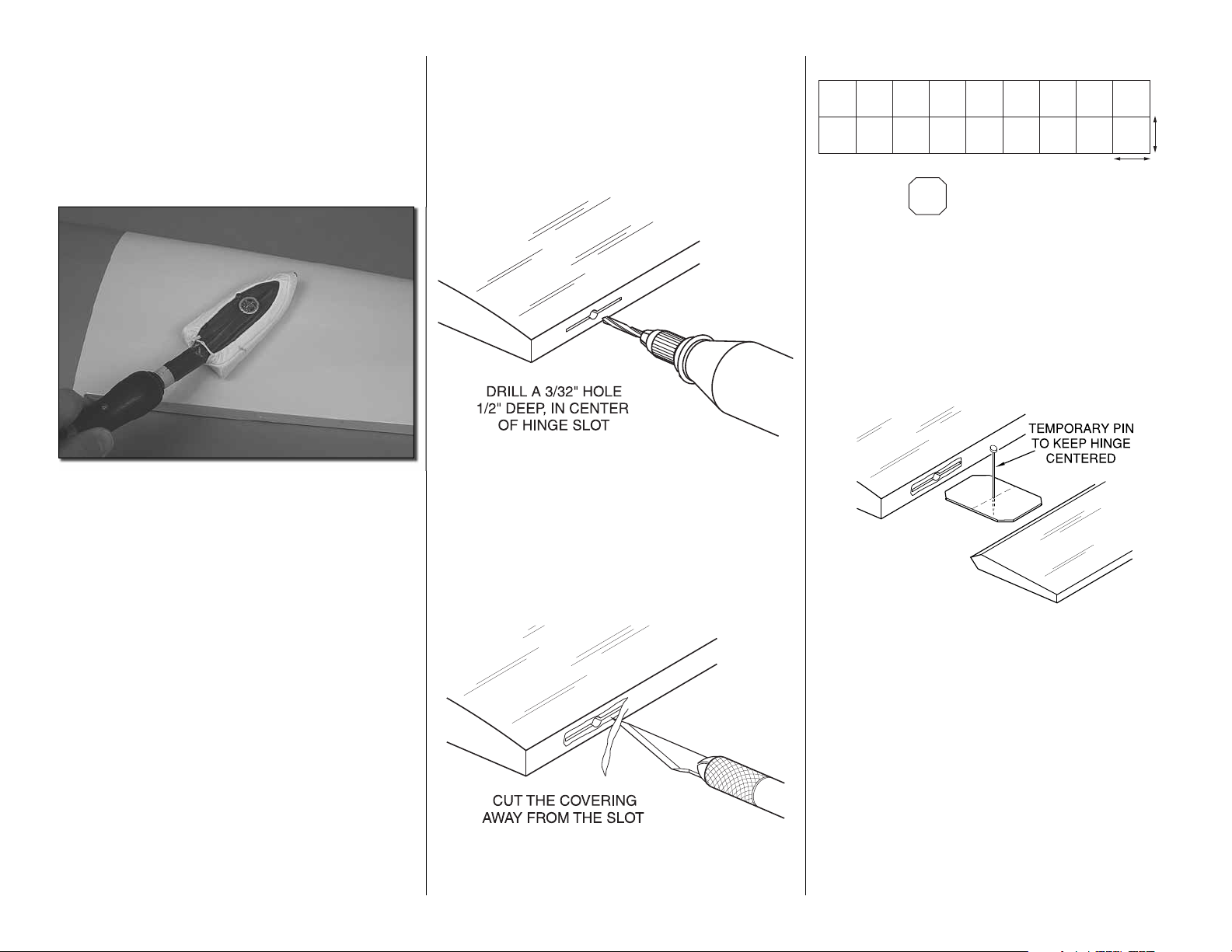
❏ ❏ 1. Drill a 3/32" hole, 1/2" deep in the center of
each hinge slot to allow the CA to “wick” in. Followup with a #11 blade to clean out the slots. Hint: If
you have one, use a high-speed rotary tool to drill
the holes.
1"
1"
CLIP CORNERS
❏ ❏ 3. Cut twelve 1" x 1" [25 x 25mm] hinges from
a CA hinge strip. Snip off the corners so they go in
easier.
❏ ❏ 2. Use a sharp #11 blade to cut a strip of covering
from the hinge slots in the wing and aileron.
6
❏ ❏ 4. Test fi t the aileron to the wing with the hinges.
If the hinges don’t remain centered, stick a pin through
the middle of the hinge to hold it in position.
❏ ❏ 5. Remove any pins you may have inserted into
the hinges. Adjust the aileron so there is a small gap
between the LE of the aileron and the wing. The gap
should be small, just enough to see light through or
to slip a piece of paper through.
Page 7
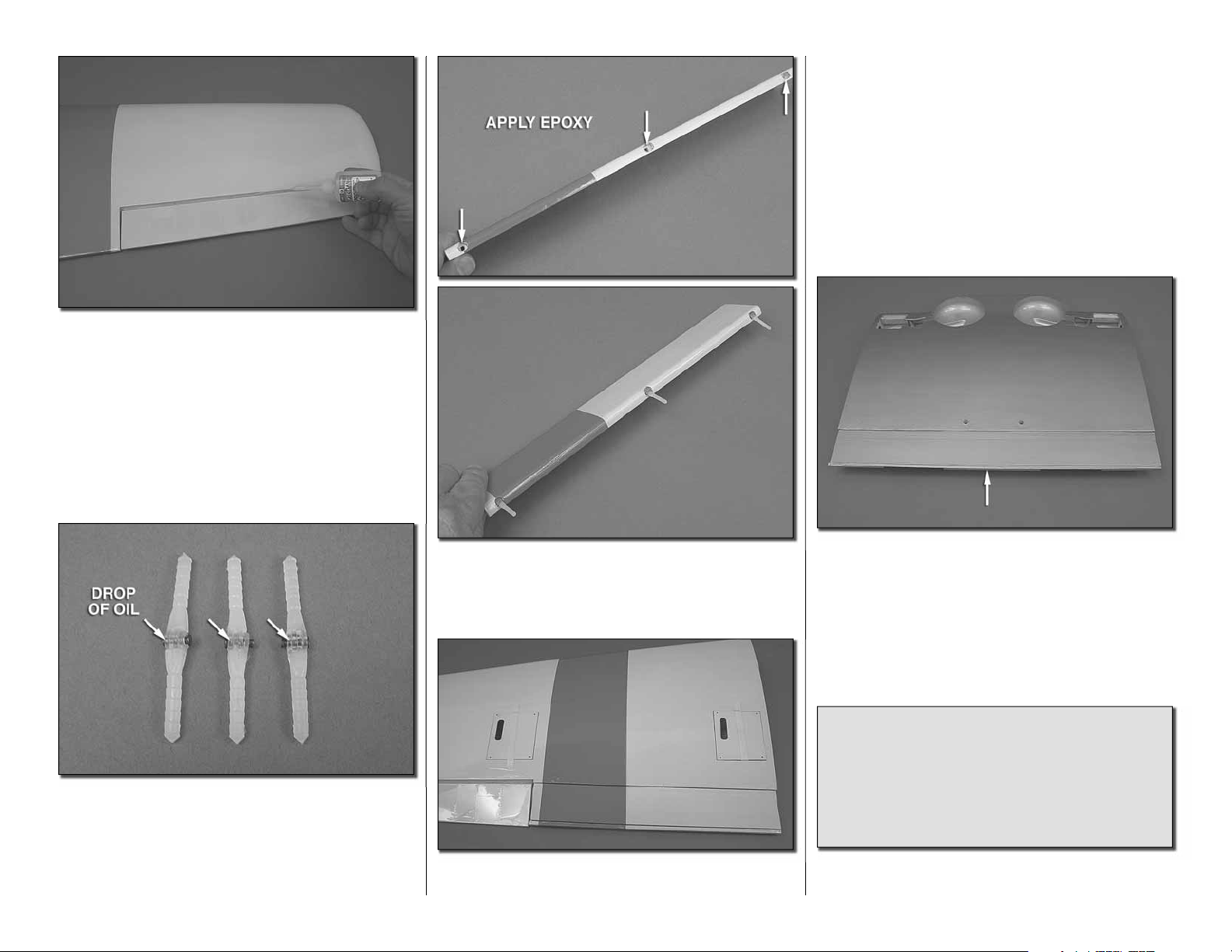
❏ ❏ 6. Apply six drops of thin CA to the top and
bottom of each hinge. Do not use CA accelerator.
After the CA has fully hardened, test the hinges by
pulling on the aileron.
the holes in the trailing edge of the wing. Insert the
fl ap into the wing. Align the hinges with the pivot
point in the hinge pocket and so the hinge pivots
perpendicular to the leading edge of the fl ap. Be sure
the fl ap is pushed close enough to the trailing edge
of the wing so the fl ap sits completely fl ush with the
bottom of the wing.
❏ ❏ 10. Set the assembly aside until the glue cures.
❏ 11. Repeat steps 1- 10 for the left wing panel.
❏❏7. Locate three hinge point hinges. Apply a
drop of oil or apply a small amount of Vaseline into
the hinge pin. This will keep glue from getting into
the hinge and preventing it from moving freely. Be
careful not to get oil on the hinge point. If you do,
clean it with a cloth and alcohol.
❏ ❏ 8. Apply 30-minute epoxy to one side of each
hinge and using a toothpick work a small amount of
epoxy into each of the holes for the hinge in the leading
edge of the fl ap. Insert one hinge into each hole.
❏ ❏ 9. Clean excess epoxy from the hinge and
fl ap. Apply epoxy to the other end of the hinge and
7
7
❏ 12. Using the same technique used for the wing
fl aps, install four hinges into the fl ap of the wing
center section.
❏ 13. After the glue has completely cured work the
fl ap hinges until they move smoothly.
Did you know…The AT-6 advanced trainer was
one of the most widely used aircraft in history.
Most AAF fi ghter pilots trained in AT-6s prior
to graduation from fl ying school. Many of the
“Spitfi re” and “Hurricane” pilots in the Battle of
Britain trained in Canada in “Harvards,” the British
version of the AT-6.
Page 8
INSTALL THE AILERON/FLAP SERVOS
AND PUSHRODS
❏ ❏ 1. Remove the aileron and fl ap covers from the
right wing panel.
❏ ❏ 3. Drill a 1/16" [1.6mm] hole through the servo
cover into the center of the servo mounting blocks.
Install and then remove a #2 x 3/8" [10mm] wood
screw into the holes you drilled. Apply a drop of thin
CA into the holes to harden the threads. Once the glue
has cured install the screws into the servo cover.
❏ ❏ 4. Install a 12" servo extension onto the servo
lead. Secure the extension to the lead with tape, a
piece of shrink tube or some other method to keep
them from coming unplugged.
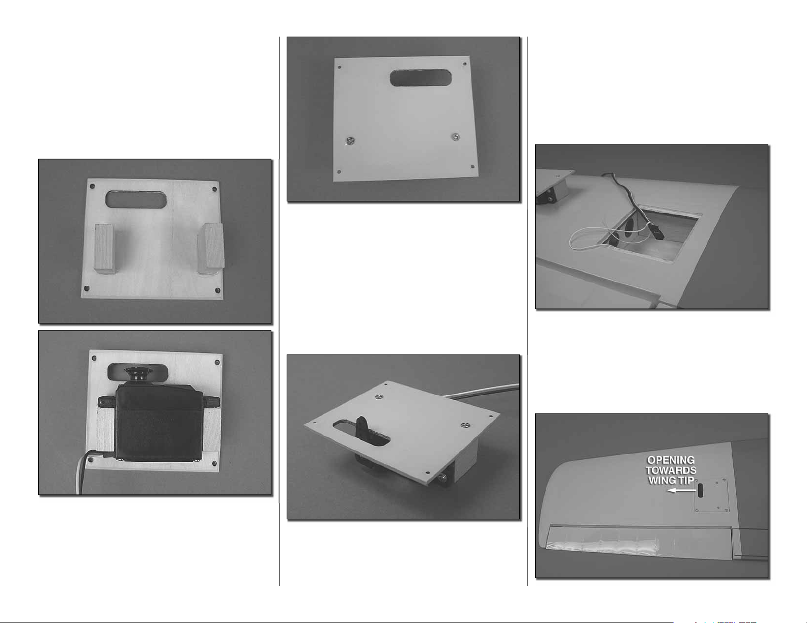
remove a servo mounting screw into each of the
holes you have drilled. Apply a drop of thin CA into
the holes to harden the threads. Once the glue has
cured install the servo onto the servo cover using the
hardware included with your servo. Center the servo.
Then install a servo arm as shown.
❏ ❏ 6. Inside the servo bay a string is taped. Tie the
string to the servo extension. Pull the string and the
servo lead through the wing. Do not untie the string
from the servo lead.
❏ ❏ 2. Glue two 5/16" x 3/4" x 3/4" [8 x 19 x 19mm]
hardwood blocks to the servo cover. Position the
blocks so the servo fi ts between the blocks and the
servo horn is centered in the opening.
❏❏5. Using a 5/64" [2mm] drill bit, enlarge the
outer hole on the servo horn. Place the servo onto
the servo mounting blocks. Drill through the servo
mounting holes with a 1/16" [1.6mm] drill bit. Remove
the servo from the servo cover. Install and then
8
Page 9
[10mm] screw into each of the holes. Apply a couple
drops of thin CA into the holes to harden the threads.
Once the glue has hardened attach the horn to the
aileron with two #2 x 3/8" [10mm] screws.
❏ ❏ 12. Place the servo onto the servo mounting
blocks. Drill through the servo mounting holes with
a 1/16" [1.6mm] drill bit. Remove the servo from the
servo cover. Install and then remove a servo mounting
screw into each of the holes you have drilled. Apply a
drop of thin CA into the holes to harden the threads.
Once the glue has cured install the servo onto the
servo cover using the hardware included with your
servo. Center the servo and then install a servo arm
as shown.
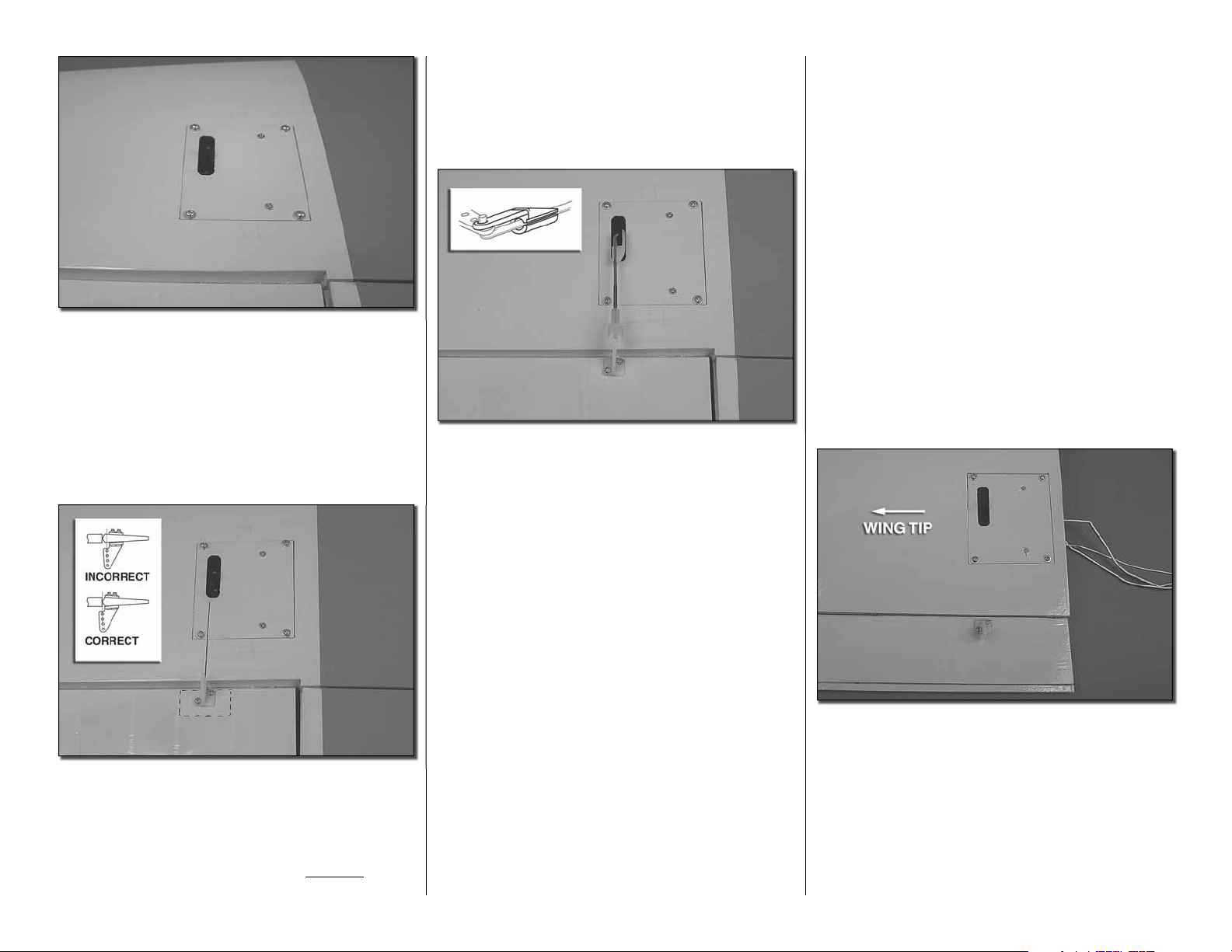
❏ ❏ 7. Place the servo cover onto the wing. The
opening for the servo arm should be pointed
towards the wing tip. Drill a 1/16" [1.6mm] hole
through each corner of the cover. Remove the cover.
Then install and remove a #2 x 3/8" [10mm] screw
into the holes you drilled. Apply a drop of thin CA
into the holes to harden the threads. Once the glue
has hardened, mount the servo cover with #2 x 3/8"
[10mm] screws and #2 fl at washers.
❏❏8. Place a nylon control horn in line with the
outer hole in the servo arm. When positioned properly
the control horn will rest on a hardwood plate in the
aileron. Mark the location of the mounting holes onto
the aileron. Drill a 1/16" [1.6mm] hole on the marks,
drilling through the plywood plate but not through
the top of the aileron. Insert and remove a #2 x3/8"
❏ ❏ 9. Screw a nylon clevis onto a .074 x 6" [152mm]
threaded wire 20 turns. Slide a nylon clevis retainer
onto the clevis. Install the clevis into the second
hole from the end of the control horn. Then slide the
silicone retainer over the clevis. Center the servo
and the aileron. With a fi ne tip marker, mark the wire
where it aligns with the outer hole of the servo arm.
Make a 90 degree bend on the mark. Cut the wire so
the wire is 3/8" [10mm] in length after the bend. Insert
the wire into the servo arm and lock it in place with a
nylon Faslink.™
❏ ❏ 10. Glue two 5/16" x 3/4" x 3/4" [8 x 19 x 19mm]
hardwood blocks to the fl ap servo cover. Position
the blocks so the servo fi ts between the blocks.
❏ ❏ 11. Drill a 1/16" [1.6mm] hole through the servo
cover into the center of the servo mounting blocks.
Install and then remove a #2 x 3/8" [10mm] wood
screw into the holes you drilled. Apply a drop of thin
CA into the holes to harden the threads. Once the glue
has cured install the screws into the servo cover.
9
❏ ❏ 13. Tie the fl ap servo lead to the string with the
aileron servo lead. This one string will be used to pull
the leads through the wing center section.
❏ ❏ 14. Place the fl ap servo cover onto the wing. For
the right wing the opening for the servo arm should
be pointed towards the wing tip. (For the left wing
the servo will be located toward the root rib.) Drill a
1/16" [1.6mm] hole through each corner of the cover.
Remove the cover. Then install and remove a #2 x
3/8" [10mm] screw into the holes you drilled. Apply a
drop of thin CA into the holes to harden the threads.
Once the glue has hardened, mount the servo cover
with #2 x 3/8" [10mm] screws and #2 fl at washers.
Page 10
❏ ❏ 16. Screw a nylon clevis onto a .074 x 6"
[152mm] threaded wire 20 turns. Slide a nylon clevis
retainer onto the clevis. Install the clevis into the
second hole from the end of the control horn. Then
slide the silicone retainer over the clevis. Position the
fl ap tight to the bottom of the wing. Position the servo
arm so that it is pointed towards the trailing edge of
the wing. With a fi ne tip marker, mark the wire where
it aligns with the outer hole of the servo arm. Make
a 90 degree bend on the mark. Cut the wire so the
wire is 3/8" [10mm] in length after the bend. Insert
the wire into the servo arm and lock it in place with a
nylon Faslink.
INSTALL THE WING JOINERS AND
JOIN THE WING HALVES
Important! Be sure to take your time and follow the
instructions for installing the wing joiners. Because of
the unusual angles of the joiner it can be confusing.
Taking your time will insure a proper assembly. It is
recommended that you read completely through the
instructions and pay attention to the pictures before
proceeding with the joiner and joining the wing.
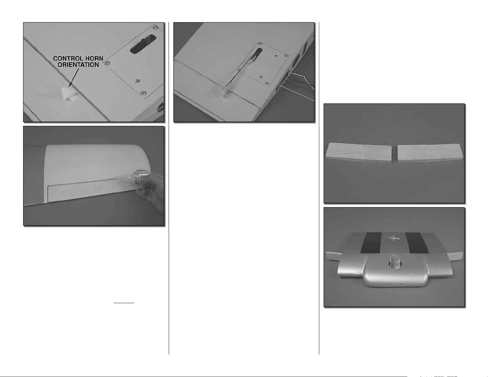
❏❏15. Place a nylon control horn in line with the
outer hole in the servo arm. Place the nylon control
horn backwards from what would be considered the
normal mounting position, in line with the outer hole
in the servo arm. (This provides better mechanical
advantage for the fl ap operation). When positioned
properly the control horn will rest on a hardwood plate
in the fl ap. Mark the location of the mounting holes
onto the fl ap. Drill a 1/16" [1.6mm] hole on the marks,
drilling through the plywood plate but not through the
top of the fl ap. Insert and remove a #2 x3/8" [10mm]
screw into each of the holes. Apply a couple drops of
thin CA into the holes to harden the threads. Once
the glue has hardened attach the horn to the fl ap with
two #2 x 3/8" [10mm] screws.
❏ 17. Repeat steps 1-15 for the left wing panel.
Important! At step 13 pay close attention to be sure
you install the fl ap servo properly for the left wing.
❏ 1. Locate two hardwood wing joiners. Slide the
joiners completely into the joiner pocket of the wing
center section. When you have the joiners matched
to the correct side of the wing center section, they will
fi t without force. There will be a slight upward angle of
the joiner extending from the center section.
10
Page 11

❏ 2. Slide the wing panels in position, making sure
that they fi t the joiner properly and are fl ush to the
center section.
❏ ❏ 3. Once you have a good fi t, remove one wing
panel and mark the joiner so you will have the proper
orientation when you permanently glue it in place.
❏ 4. Repeat step 3 for the other joiner.
❏ 5. On each outer rib of the center section there is a
string taped. Remove the tape and re-apply the tape
and string onto the top of the center section.
❏ ❏ 7. Tie the aileron and fl ap servo lead string from
the wing to the string from the wing center section.
❏❏8. Pull the servo leads into the wing center section
❏ ❏ 9. Locate one of the 1/32" x 2-3/8" [1 x 61mm]
piano wires. On the end of the fl ap there is a small
hole. Insert the wire into the hole. No glue is used
on this wire!
❏ ❏ 10. Apply epoxy to the other end of the wing
joiner, the joiner pocket in the outer wing panel, the
rib of the wing center section and the rib of the outer
wing panel.
❏ ❏ 6. Liberally apply 30 minute epoxy to the end of
the wing joiner that fi ts into the wing center section
and into the joiner pocket of the wing center section.
Slide the joiner into the pocket. Any excess glue that
may come out when the joiner is inserted can be
spread onto the outer rib of the wing center section.
❏❏11. Slide the wings together, making sure you
pull the servo leads into the center section. The wire
needs to be slid into the hole in the outer wing panel
fl ap. Once you are sure the wire is in the hole of both
the center and outer wing panel fl aps, slide the two
panels together.
11
Page 12

❏❏12. Tape the panels together and set the wing
aside until the glue has cured. Open up the fl ap so
that they are not accidentally glued shut. (When you
open the outer fl ap, the fl ap in the center section
should move with the outer fl ap. If not, pull the wings
apart and be sure the piano wire is in the holes of
both the outer wing and center section fl aps.) If there
are small gaps where the two panels join, don’t worry
about correcting this. There is a joiner cover that will
be glued over the joint in a later step.
edge of the wing. Once fully inserted, mark the dowel
with a pencil to know how much of the dowel to apply
glue to. Apply epoxy into the holes in the leading edge
of the wing center section and a fi lm of epoxy onto
the dowels. Insert them into the holes. Wipe excess
epoxy from the dowels with rubbing alcohol.
❏ 16. Once properly positioned draw the outline onto
the top and bottom of the wing with a fi ne tip marker.
❏ 13. Repeat steps 6-13 for the left wing panel.
❏ 14. Locate two 1/4" x 7/8" [6 x 48mm] wood dowels.
Push them all the way into the holes in the leading
❏ 15. Locate the two joiner covers. Trial fi t one of
these over the wing joint.
12
❏ 17. Between the lines you drew, cut away the
covering in three or four locations along the width of
the wing. Apply epoxy to the exposed wood areas.
Then, position the joiner in place over the wing joint.
Clamp or hold the joiner in place until the glue cures.
Did you know…Variously called the Texan (USAAF),
Harvard (RAF), Yale, I-Bird, Mosquito, Wirraway
(Australia), T-6 and SNJ (USN), the AT-6 appeared
in 1940. In all, over 17,000 aircraft were produced,
not taking into account the numbers rebuilt from
existing airframes, or others that used the AT-6
technology, such as the P-64 or Boomerang.
Page 13

INSTALL THE RETRACTABLE LANDING GEAR
AND WHEELS
❏ 1. This step is recommended but optional. Mix a
small amount of epoxy and thin it 40% with alcohol.
Brush the epoxy into the cavity of the wheel area to
fuel proof inside the wing. You could also choose to
do this with a high-quality black paint to fuel proof it
and give it a more fi nished look.
thread locker onto the set screw. Then re-insert it and
tighten it against the landing gear wire. Do this for
both gear.
❏ ❏ 5. On the marks you made for the location of the
landing gear drill a 1/8" [3mm] hole through the rails.
Do not drill through the top of the wing! Insert and
remove a #6 x3/4" [19mm] screw into each of the
holes. Apply a couple drops of thin CA into the holes
to harden the threads. Allow the glue to harden.
❏ 2. Install your retract servo between the mounting
rail in the wing center section using the hardware that
came with the servo.
❏ ❏ 3. Position the landing gear onto the landing
gear rails as shown here. With a pencil or fi ne tip
marker, mark the location of the holes for mounting
the retracts.
❏ ❏ 4. Remove the set screw from each side of
the landing gear mount. Apply a couple of drops of
13
❏ ❏ 6. Locate one of the 6" [152mm] wires with the
“Z” bend on the end. Insert the end with the “Z” bend
into the connector on the end of the retract unit.
Page 14

❏ ❏ 7. Insert the 12" [305mm] fl exible plastic tube
into the wheel opening, sliding it into the wing until it
exits out at the retract servo.
❏ ❏ 9. Mount the retract to the rail with four #6 x 3/4"
[19mm] screws and four #6 fl at washers.
❏ ❏ 10.File a fl at spot onto the end of the axle.
5mm wheel collars. Slide one wheel collar onto the
axle followed by the wheel and another wheel collar.
Position the outer wheel collar at the end of the axle
and then tighten the set screw against the fl at spot
you created on the axle. Push the inner wheel collar
against the wheel but not tight enough to interfere with
the wheel's ability to spin freely on the axle.
❏ ❏ 12. Snap the wheel cover onto the wheel. Be
sure the wheel spins freely. If not, most likely the
wheel collar needs to be adjusted so it is not rubbing
against the wheel cover.
❏ 13. If you have not been doing both retracts, repeat
steps 3-13 for the other landing gear
❏ ❏ 8. Insert the wire from the retract into the tube.
Using the tube as a guide, push the wire into the wing
until the landing gear can rest on the landing gear
rails. Remove the plastic tube.
❏ 14. We will cover how to set up and adjust the
retract servo and the landing gear when we get to the
radio installation instructions.
❏ ❏ 11. Apply a drop of thread locker to two 2mm
set screws. Then thread the set screws into two
14
Page 15

BUILD THE FUSELAGE
INSTALL THE STABILIZERS, ELEVATORS
AND RUDDER
For the installation of the stabilizer you will need to
have rubbing alcohol on hand for clean up. If you do
not have any, DO NOT START THIS INSTALLATION
UNTIL YOU DO! It is suggested that you read the
next few steps to better understand the process
before actually gluing components in place.
❏ 3. Inside of the line you have marked, cut the
covering from the stabilizer following the method in
the “Hot Tip” that follows or use a sharp hobby knife
making sure you do not cut into the surface of the
wood. Cutting the surface of the wood will weaken
the structure! Be sure to cut the covering from the
top, bottom and the end of the horizontal stabilizer.
HOW TO CUT COVERING FROM BALSA
❏ 4. Slide the stab into the opening in the rear of the
fuselage. Stand back a few feet and look at the stab in
relation to the wing. The stab should be parallel and
in line with the wing. If you fi nd that your stab is not
aligned, adjust the stab by removing small amounts
of the stab saddle with 100 grit sand-paper.
❏ 1. Temporarily attach the wing to the fuselage with
two 1/4 - 20 nylon wing bolts. Slide the horizontal
stabilizer in place in the back of the fuselage. Position
the stab so that it is equal in length on both sides of
the fuselage and that the distance from the wing tip
to the stabilizer tip is equal.
❏ 2. When you are satisfi ed with the positioning,
mark the outline of the fuselage onto the top and the
bottom of the stabilizer with a fi ne point - felt tip pen.
Use a soldering iron to cut the covering from the
stab. The tip of the soldering iron doesn’t have
to be sharp, but a fi ne tip does work best. Allow
the iron to heat fully. Use a straightedge to guide
the soldering iron at a rate that will just melt the
covering and not burn into the wood. The hotter
the soldering iron, the faster it must travel to melt
a fi ne cut. Peel off the covering.
15
❏ 5. Locate the stab fi ller block. Cut the covering
from the block as shown.
❏ 6. Locate the elevator joiner wire. Insert it into the
slots in the fi ller block, making sure it can move easily
in the slots.
Page 16

❏ 7. Locate one of the 2-56 x 36" [914mm] pushrod
wires. Onto the threaded end of the wire install a
silicone clevis keeper, 2-56 nut and a 2-56 metal
clevis, 15 to 20 turns. Apply a couple of drops of
thread locker onto the threads. Then tighten the nut
against the clevis.
❏ 8 Slide the end of the wire into the plastic tube at
the stab opening in the fuselage.
trailing edge of the stab. Be careful not to get glue on
the wire.
❏ 10. Position the fi ller block in the back of the stab
opening. Locate the joiner wire into the fi ller block
as shown. Apply a couple of drops of oil to the wire as
done with the fl ap hinges.
❏ 9. Place the joiner wire into the stab opening and
attach the clevis into the last hole in the arm of the joiner
wire. Slide the silicone clevis keeper over the clevis.
❏ 12. Move the stab to the right and left, exposing
the wood where you cut the covering away. Apply
30-minute epoxy to the wood on both the top and
bottom of the stab. Work the glue into the stab opening
by moving the stab back and forth. When you are
satisfi ed with the penetration of the glue, clean away
the excess epoxy from the stab and fuselage with a
cloth dampened with alcohol. Once cleaned, double
check the stab position and check to be sure the wing
joiner wire moves freely. Set it aside to cure.
❏ 11. Slide the stab into the stab opening. Apply
a small amount of glue to the block, gluing it to the
16
Page 17

should be small, just enough to see light through or to
slip a piece of paper through. Apply six drops of thin
CA to the top and bottom of each hinge. Do not use
CA accelerator. After the CA has fully hardened, test
the hinges by pulling on the elevator. Do this for both
elevator halves.
❏ 13. On the bottom of the fuselage there is a hole
that is large enough to get a forceps or small pliers up
to the clevis. Should you ever need to make additional
adjustments to the clevis, you can cut the covering
away to reveal the hole. The hole can be covered over
with the small piece of silver MonoKote included in
the kit.
❏ 14. Apply a small amount of epoxy into the slot and
hole for the joiner wire in each elevator half.
❏ 15. Cut nine 1" x 1" [25 x 25mm] hinges from a
CA hinge strip. Insert three hinges into the elevator. If
the hinges don’t remain centered, stick a pin through
the middle of the hinge to hold it in position. Slide the
hinges into the elevator.
❏ 16. Remove any pins you may have inserted into
the hinges. Adjust the elevator so there is a small gap
between the LE of the elevator and the stab. The gap
❏ 17. Apply a couple of drops of oil into the nylon
bearing. This will prevent glue from getting into the
joint and causing the rudder to bind.
❏ 18. Apply a small amount of epoxy into the hole and
the slot in the rudder. Insert the tail wheel assembly
into the rudder and allow the glue to cure.
17
❏ 19. Install three hinges into the rudder the same as
done with the elevator. Test fi t the rudder to the fi n. If
necessary, use your modeling knife to adjust the hinge
slot for the nylon bearing. When installing the rudder,
the nylon bearing from the tail wheel assembly must
also fi t into the fi n. Once satisfi ed with the fi t, remove
the rudder. Put some epoxy onto each side of the
nylon bearing. Then re-insert the rudder back onto
the fi n. When you are satisfi ed with the fi nal fi t apply
six drops of thin CA to both sides of each hinge.
❏ 20. Slide the tail wheel onto the tail wheel wire.
Secure it in place with a 1/8" [3mm] wheel collar
and 2-56 set screw. Be sure to use threadock on the
set screw.
Page 18

❏ 21. Screw a nylon clevis onto a .074 x 36" [914mm]
threaded wire 20 turns. Slide a nylon clevis retainer
onto the clevis. Install the clevis into the outer hole
of the control horn. Then slide the silicone retainer
over the clevis. Mark the location for the control horn
onto the rudder. Drill a 1/16" [1.6mm] holes into the
plywood plate in the rudder. Do not drill through the
rudder. Secure the horn to the rudder with #2 x 3/8"
[10mm] screws.
INSTALL THE ENGINE FUEL TANK
AND THROTTLE SERVO
❏ 1. Bolt the engine mount to the fi rewall with four
8-32 x 1" [25mm] socket head cap screw, #8 lock
washer and #8 fl at washer. Place your engine on the
mount and adjust the mounting rail position to match.
Then tighten the bolts.
❏ 3. Install the engine to the mount with four each,
8-32 x 1" [25mm] socket head cap screws, #8 lock
washers and #8 fl at washers.
A
B
C
A: TO MUFFLER
B: TO CARBURETOR
C: FILL LINE
Did you know…The AT-6 Texan became the
classroom for the majority of the Allied pilots who
fl ew in World War II, and trained several hundred
thousand pilots in 34 different countries. Its basic
design was as a trainer, with the characteristics
of a high speed fi ghter, and was well suited to the
intermediary task of training pilots before letting
them loose in an actual fi ghter aircraft. Although
not as fast as a fi ghter, it was easy to maintain and
repair, had more maneuverability and was easier to
handle. A pilot’s airplane, it could roll, Immelmann,
loop, spin, snap, and vertical roll. It was used to
train pilots in all aspects of tactical operations, such
as dog-fi ghting, ground strafi ng, carrier landings,
and bombardment. It also included the capacity for
fi xed and fl exible guns, cameras, and just about
any other device that the military required.
❏ 2. Position the engine on the mount so the distance
from the fi rewall to the front of the thrust washer
measures 5-11/16" [145mm]. Mark the location of
the engine on the mount. The Great Planes® “Dead
Center” Hole Locator (GPMR8130) works well for
this. Drill through the marks you have made with a
#29 or 9/64" [3.6mm] drill bit. Tap each hole with an
8-32 tap.
18
❏ 4. Assemble the fuel tank as shown in the sketch.
When tightening the center screw, be sure not to
overtighten it. You just want it snug enough to pull the
rubber stopper tight against the tank.
❏ 5. Install silicone fuel tubing (not supplied) onto
the aluminum tubes from the fuel tank. One line with
the fuel clunk will feed to the fuel inlet at the needle
valve. The second line with the fuel clunk will be the
line to fi ll the tank. The remaining line will attach to
the pressure tap on the muffl er. The fi ll line should
be plugged after fueling with the aluminum fuel plug
provided with the kit.
Page 19

❏ 6. Locate the 6 x 6 x 90mm hardwood stick. Glue
it in position on the fuselage former as shown. The
stick should be glued on line with the visible tab slot.
the center slots of the battery/receiver/fuel tank tray.
Put the tray in position in the front of the fuselage. Note
that the tray is cut at an angle to match the right thrust
that is built into the fi rewall. On the front of the tray
there are three tabs that will lock into slots in the back
of the fi rewall. Slide the tabs into those slots and let
the tray rest on the hardwood stick you just installed.
In each corner of the tray there is a small hole. Using
them as your guide, drill through the hole with a 1/16"
[1.6mm] drill bit into the hardwood stick. Install and
remove a #2 x 3/8" [10mm] screw into each hole.
Apply a drop of thin CA in each hole. After the glue
hardens, secure the tray to the hardwood stick with
two #2 x 3/8" [10mm] screws and two fl at washers.
❏ 7. Cut two 6" [152mm] pieces of Velcro. Secure
them to each other then insert the Velcro strap though
❏ 8. Slide the neck of the fuel tank into the hole in
the fi rewall and rest the tank on the tray. Secure the
tank to the tray with the Velcro strap. Note: We will
not connect the fuel lines at this time because we will
be removing and reinstalling the tank when we install
the radio.
❏ 9. Install a brass screw lock connector onto the
outer hole of the engine throttle arm. Lock it to the
arm with the nylon retainer. Screw a 4-40 x 1/8" [3mm]
socket head cap screw into the brass connector.
19
❏ 10. Determine the position where the throttle
pushrod will pass through the fi rewall. When
determining this, make sure the fuel tank does not
interfere with the pushrod. If you will be drilling very
close to the tank we recommend that you remove it
to prevent accidentally drilling through the tank. Drill
a 3/16" [4.8mm] hole in the fi rewall. Locate the 12"
[305mm] plastic pushrod tube. Roughen one end of
the tube. Then slide the tube into the hole you drilled.
Glue the tube to the fi rewall. Cut the plastic tube
just behind the fuselage former as shown. Bend the
pushrod wire as needed to allow for free movement
of the wire and the throttle arm. Secure the wire to the
connector with the 4-40 bolt.
Page 20

CUT OFF
UNUSED
ARMS
❏ 11. Install the servo into the servo tray as shown.
Drill a 1/16" [1.6mm] hole through each of the servo
mounting holes. Insert and remove one of the servo
screws into each of the holes. Apply a couple drops of
thin CA into the holes to harden the threads. Once the
glue has hardened, attach the servo to the tray with
four #2 x 3/8" [10mm] screws and #2 fl at washers.
Remove the servo arm and cut off the unused arms.
Install a brass screw lock connector into the outer hole
of the remaining servo arm. Slide the wire through
the connector; re-attach the servo arm to the servo.
Secure the pushrod wire to the servo with a 4-40 x
1/8" [3mm] socket head cap screw.
INSTALL THE RADIO SYSTEM
❏ 1. Remove the fuel tank and the tray from the
fuselage and set it aside.
❏ 2. Use the wire pushrods as your guide for
positioning the rudder and elevator servos. Install the
servos using the same procedure used for the other
servos, mounting them onto the servo rails. Install the
servo arms onto the servos as shown.
❏ 4. On the underside of the tray that the fuel tank
mounts to, install the receiver and battery onto ¼"
[6mm] foam and secure them to the tray with Velcro
straps. Plug the servos into the appropriate channels
in the receiver. Be sure to plug in a 12" [305mm]
servo extension for the retractable landing gear, fl aps
and aileron servos. Route the lead from the battery
through one of the slots for the Velcro so that after the
tray is re-installed you will be able to attach a switch
to the battery. Install the tray back into the fuselage
and re-install the fuel tank
❏ 3. Using a 5/64 [2mm] drill bit, enlarge the outer
hole of the servo arms. Center the servos, elevator and
rudder. With a fi ne tip marker, mark the wires where
they align with the outer hole of the servo arms. Make
90° bends on the marks. Cut the wires so they are 3/8"
[10mm] in length after the bend. Insert the wires into
the servo arms and lock in place with nylon Faslinks.
20
❏ 5. Plug your switch harness into the battery and
secure the connector with heat shrink tube, tape or
some other method to be sure the battery cannot
Page 21

become unplugged. Mount the switch on the fuselage
opposite the exhaust. There are a number of after
market switch mounts. We used the Ernst Charge
Receptacle (ERNM3001) for Futaba radios.
❏ 6. Route the antenna through the fuselage to the
antenna tube and feed the wire into the tube.
❏ 7. Plug the two fl ap servos and the two aileron
servos into “Y” harnesses. Secure the servos to the
“Y” harness with shrink tubing, tape or some other
method to keep them from becoming unplugged.
❏ 8. With your radio system turned on, adjust the
position of all of the servo arms and linkages until all
of the control surfaces are neutral.
FINAL SET-UP OF THE RETRACTABLE
LANDING GEAR SERVO
Mechanical retracts work very well when properly set
up but they can be a little tedious. The following will
help minimize your time required to set them properly.
❏ 1. Depending on the brand of retract servo you use,
you may have to experiment with the length of the servo
arm. We used the standard six arm servo, cutting off
the arms except two that were 180 degree opposite
of each other. In the outer hole of each arm install a
brass screw lock connector and nylon retainer.
❏ 2. Turn on your radio and plug the retract servo
into the receiver. Most likely your radio will have a two
position switch. In one direction the switch will raise the
landing gear; the other direction will lower it. Pick up
the servo arm. Slide one of the wires from the landing
gear into one of the brass screw lock connectors and
the other wire into the other connector. Install the
servo arm onto the servo but do not put the screw
in place to hold it to the servo and do not install the
screws into the screw lock connector.
❏ 3. Flip the switch on the radio to see which way
the servo arm will rotate. The servo arm will need to
travel the same amount in both directions. Adjust the
position of the servo arm as needed to achieve this.
Install the screw to hold the servo arm in place on
the servo.
21
❏ 4. The retracts move the landing gear up and down
by either pulling the wires or pushing them. Pulling
the wire will extend the landing gear. Find the switch
position that the servo arm will pull the wires. Pull
hard on the wire, locking the landing gear into the
extended position. Install a 4-40 x 1/8" [3mm] socket
head cap screw with threadlock into each of the
screw lock connectors, tightening the screw against
the wire.
❏ 5. Flip the switch on the radio to make the landing
gear retract into the wheel. If everything is set
properly the wheels will retract into the wing and lock
into place. Flipping the switch back the other direction
will extend the gear and lock them into the extended
position. If your wheels do not extend or retract fully
you will need to adjust the amount of throw you are
getting from the servo. If you need more throw you
can consider using a longer servo arm. If you are
getting too much throw you can use a smaller servo
arm. If you are using a radio that has adjustable travel
volume you may be able to adjust the amount of throw
by adjusting it through the radio. Make whatever
adjustments are needed to get the landing gear to
lock in both the up and down positions. Be sure that
the servo does not bind or it will draw current from
the battery that could shorten your fl ight times. Have
a little patience and take the time to make sure the
gear work properly before your fi rst fl ight.
Did you know…The North American Texan trainer
is one of the most important aircraft of all time and
is universally recognized. First built as the NA-16
in 1935, the Texan was in continual production for
nearly 10 years and in active use for more than
fi ve decades. Primarily used as a trainer, the
Texan remains a favorite among Warbird collectors
around the world.
Page 22

INSTALL THE COWL & DUMMY ENGINE
❏ 1. Locate four 1/2" x 1/2" x 1" [13 x 13 x 25mm]
hardwood cowl mounting blocks. On each block mark
a line 1/4" [6mm] from the end of the block.
❏ 4. Once the cowl fi ts over the engine, position it on
the cowl mounting block so that the engine is centered
inside. To allow for proper clearance you may fi nd it
helpful to place a propeller onto the engine. Once you
are satisfi ed with the placement of the cowl, mark the
location of the cowl mounting blocks on the cowl with
a fi ne tip felt marker. Hint: The cowl mounting blocks
are very close to the back edge of the cowl. You should
be able to easily see the location of each of the blocks
from behind the cowl, allowing you to properly mark
each position onto the cowl.
you drilled. Repeat this for each of the four mounting
blocks. As you drill each hole double check to be sure
your cowl remains centered on the engine. Remove
the screws and cowl. Apply a couple drops of thin CA
into the holes to harden the threads.
❏ 6. Cut away the portion of the dummy engine that
will be in front of the engine cylinder. This is needed
for proper cooling of the engine. When determining
the exact location to cut, note that cylinders should
be oriented as shown in the picture. We were able to
cool the O.S. .91 by only cutting away a small portion
of the cylinders as shown in the picture.
❏ 2. Epoxy each block to the front of the fuselage. Use
the line you made as a guide for positioning the block.
The line should be fl ush with the fuselage. One block
should be mounted at each of the twelve, three, six
and nine o’clock positions on the front of the fuselage.
❏ 3. Position the cowl onto the front of the fuselage.
As you place the cowl you may fi nd that you will
need to make cut outs in the cowl to accommodate
the cylinder head, muffl er, needle valve, etc. Cut
openings in the cowl as needed.
❏ 5. Start with the top cowl mounting block. Double
check the position of the cowl. Then, on the mark you
made on the cowl, drill through the cowl and into the
mounting block with a 3/32 [2.4mm] drill. Install a #4 x
5/8" [16mm] screw and a #4 fl at washer into the hole
22
❏ 7. Drill a 1/8" [3mm] hole into each of the cylinder
heads as shown.
Page 23

❏ 8. Drill a 1/8" [3mm] hole into each of the crankcases
as shown.
❏ 10. Slide the dummy engine over the engine shaft,
and then slide the cowl in place. Rotate the dummy
engine so it is properly positioned over the engine.
Attach the cowl to the fuselage with the #4 screws.
Use two sticks and two rubber bands (not included)
to hold the dummy engine in place. Loop the rubber
bands around the aluminum tubes. Then slide the
stick through the rubber bands. This will temporarily
secure the dummy engine in place.
❏ 12. Re-install the cowl. Install your propeller and
spinner. Be sure to use thread locking compound on
the screw that holds the spinner to the back plate.
❏ 9. Install one of the 1/8" aluminum tubes into
each of the sets of holes. Apply a drop of glue on
the backside of the dummy engine where the tube
contacts the plastic to keep them in place.
❏ 11. Carefully remove the cowl. From inside the
cowl, tack glue the dummy engine in place. When
you are satisfi ed with the fi t and position, mix a small
amount of 6-minute epoxy and make a fi llet of glue
inside the cowl to hold the dummy engine in place.
Allow the glue to cure.
23
Page 24

INSTALL THE COCKPIT AND REMAINING
SCALE DETAILS
❏ 1. Glue the black plastic cockpit fl oor to the fuselage.
instrument panel back 4-1/4" [107mm]. This is where
the front legs of the post should be glued. Glue the
turn-over post in place at that position
❏ 3. Locate the plastic instrument panel housing and
glue the instrument panel into it.
❏ 2. Locate the two instrument panels. Cut out the
instrument panel from the decal sheet. Place the
decal in place on the back of the instrument panel. The
instruments are not placed symmetrically so there is
a front and back side of the instrument panel. Once
you have determined which is the back side of the
instrument panel, glue the decal of the instruments
to the back side of the panel.
❏ 4. Glue the front instrument panel in place in the
front of the cockpit.
❏ 5. Temporarily place the turn-over post in the
center of the cockpit. Measure from the base of the
24
❏ 6. Glue the rear instrument panel, seat backs and
pilots in place as shown.
Page 25

❏ 7. Place the canopy over the cockpit. You can either
glue it permanently to the fuselage or mount it with
screws. If you choose to glue it in place, Super Z RC56
works well. If you screw it in place, drill a 1/16" [1.6mm]
hole at the front and rear sides of the canopy on both
sides of the fuselage. Screw the canopy in place with
four #2 x 3/8" [10mm] screws. After installing the
screws, remove them and apply a couple of drops of
thin CA into the holes to harden them. After the glue
has cured, re-install the canopy.
❏ 9. There are two air scoops. One is taller than the
other. The taller of the two will be mounted to the left
side of the fuselage and the other will mount on the
bottom of the fuselage.
❏ 11. This scoop is only glued to the fuselage. The
portion that extends over the wing does not get glued
to the wing. Doing so will prevent you from removing
the wing from the fuselage. Using the same procedure
as the other scoop, glue the scoop to the bottom of
the fuselage.
❏ 8. Locate the black exhaust stack. Mark the location
for it onto the fuselage. Cut a small amount of the
covering away to create a solid place for gluing. Use
80-grit sandpaper and roughen the fl at side of the stack
that glues to the fuselage. Glue it to the fuselage.
❏ 10. Using the same procedure used for the exhaust
stack, glue the scoop to the left side of the fuselage.
25
Page 26

APPLY THE DECALS
Cut the decals from the decal sheet. Use the these pictures and the pictures on the box for determining where to place the decals.
26
Page 27

Did you know…Few aircraft make the jump from
mere machine to legend, and the AT-6 Texan can
stand proudly beside the likes of the Sopwith Camel,
B-17 Flying Fortress, B-24 Liberator, Spitfi re, or the
P-51 Mustang.
GET THE MODEL READY TO FLY
CHECK THE CONTROL DIRECTIONs
❏ 1. Turn on the transmitter and receiver and center
the trims. If necessary, remove the servo arms from
the servos and reposition them so they are centered.
Reinstall the screws that hold on the servo arms.
❏ 2. With the transmitter and receiver still on, check
all the control surfaces to see if they are centered.
If necessary, adjust the clevises on the pushrods to
center the control surfaces.
4-CHANNEL RADIO SETUP
(STANDARD MODE 2)
SET THE CONTROL THROWS
Use a Great Planes AccuThrow™ (or a ruler) to
accurately measure and set the control throw of each
control surface as indicated in the chart that follows. If
your radio does not have dual rates, we recommend
setting the throws at the high rate setting. NOTE:
The throws are measured at the widest part of the
elevators, rudder and ailerons.
ELEVATOR MOVES UP
RUDDERS MOVE RIGHT
RIGHT AILERON MOVES UP
LEFT AILERON MOVES DOWN
FULL THROTTLE
❏ 3. Make certain that the control surfaces and
the carburetor respond in the correct direction as
shown in the diagram. If any of the controls respond
in the wrong direction, use the servo reversing in
the transmitter to reverse the servos connected to
those controls. Be certain the control surfaces have
remained centered. Adjust if necessary.
27
IMPORTANT: The AT-6 has been extensively
fl own and tested to arrive at the throws at which
it fl ies best. Flying your model at these throws
will provide you with the greatest chance for
successful fi rst fl ights. If, after you have become
accustomed to the way the AT-6 fl ies, you would
like to change the throws to suit your taste, that is
fi ne. However, too much control throw could make
the model diffi cult to control, so remember, “more
is not always better.”
Page 28

These are the recommended
control surface throws:
LOW RATE
ELEVATOR: 1/2" [13mm], 8° up
1/2" [13mm], 8° down
RUDDER: 1-1/4" [32mm], 15° left
1-1/4" [32mm], 15° right
AILERONS: 3/4" [19mm], 19° up
3/4" [19mm], 19° down
FLAPS: 1" [25mm], 26° up
1" [25mm], 26° down
HIGH RATE
ELEVATOR: 5/8" [16mm], 11° up
5/8" [16mm], 11° down
RUDDER: 1-3/4" [44mm], 22° left
1-3/4" [44mm], 22° right
AILERONS: 1" [25mm], 26° up
1" [25mm], 26° down
FLAPS: 1-3/8" [35mm], 38° up
1-3/8" [35mm], 38° down
BALANCE THE MODEL (C.G.)
More than any other factor, the C.G. (balance point)
can have the greatest effect on how a model fl ies,
and may determine whether or not your fi rst fl ight
will be successful. If you value this model and wish
to enjoy it for many fl ights, DO NOT OVERLOOK
THIS IMPORTANT PROCEDURE. A model that
is not properly balanced will be unstable and
possibly unfl yable.
At this stage the model should be in ready-to-fl y
condition with all of the systems in place including
the engine, landing gear, covering and paint, and the
radio system.
4-1/4" [108mm]
balanced up-side down. The C.G. is located 4-1/4"
[108mm] back from the leading edge of the bottom
wing, measured where the center section of the wing
and the outer wing panel join.
This is where your model should balance for the
fi rst fl ights. Later, you may wish to experiment by
shifting the C.G. up to 1/4" [6mm] forward or 1/4"
[6mm] back to change the fl ying characteristics.
Moving the C.G. forward may improve the
smoothness and stability, but the model may then
require more speed for takeoff and make it more
diffi cult to slow for landing. Moving the C.G. aft
makes the model more maneuverable, but could
also cause it to become too diffi cult to control. In
any case, start at the recommended balance
point and do not at any time balance the model
outside the specifi ed range.
❏ 2. With the wing attached to the fuselage, all parts
of the model installed (ready to fl y) and an empty
fuel tank, place the model upside-down on a Great
Planes CG Machine, or lift it upside-down at the
balance point you marked.
Note: When fl aps are deployed you can expect
the airplane to balloon slightly. To minimize this we
mixed 1/32" [0.8mm] down elevator trim when the
fl aps were deployed. If you have a fl ap to elevator
mix you may wish to consider this mix as well.
❏ 1. Use a felt-tip pen or 1/8" [3mm]-wide tape to
accurately mark the C.G. on the top of the wing on
both sides of the fuselage. The model should be
28
❏ 3. If the tail drops, the model is “tail heavy” and the
battery pack and/or receiver must be shifted forward
or weight must be added to the nose to balance. If the
nose drops, the model is “nose heavy” and the battery
pack and/or receiver must be shifted aft or weight must
be added to the tail to balance. If possible, relocate
the battery pack and receiver to minimize or eliminate
any additional ballast required. If additional weight is
required, nose weight may be easily added by using
Great Planes (GPMQ4485) “stick-on” lead. A good
place to add stick-on nose weight is to the fi rewall
(don’t attach weight to the cowl—it is not intended
to support weight). Begin by placing incrementally
increasing amounts of weight on the bottom of the
fuse over the fi rewall until the model balances. Once
you have determined the amount of weight required,
it can be permanently attached. If required, tail weight
may be added by cutting open the bottom of the fuse
and gluing it permanently inside.
Page 29

Note: Do not rely upon the adhesive on the back of the
lead weight to permanently hold it in place. Over time,
fuel and exhaust residue may soften the adhesive
and cause the weight to fall off. Use #2 sheet metal
screws, RTV silicone or epoxy to permanently hold
the weight in place.
4. IMPORTANT: If you found it necessary to add
any weight, recheck the C.G. after the weight has
been installed.
BALANCE THE MODEL LATERALLY
❏ 1. With the wing level, have an assistant help you
lift the model by the engine propeller shaft and the
bottom of the fuse under the TE of the fi n. Do this
several times.
❏ 2. If one wing always drops when you lift the model,
it means that side is heavy. Balance the airplane by
adding weight to the other wing tip. An airplane that
has been laterally balanced will track better in
loops and other maneuvers.
PREFLIGHT
IDENTIFY YOUR MODEL
No matter if you fl y at an AMA sanctioned R/C club
site or if you fl y somewhere on your own, you should
always have your name, address, telephone number
and AMA number on or inside your model. It is required
at all AMA R/C club fl ying sites and AMA sanctioned
fl ying events. Fill out the identifi cation tag on the decal
sheet and place it on or inside your model.
CHARGE THE BATTERIES
Follow the battery charging instructions that came with
your radio control system to charge the batteries. You
should always charge your transmitter and receiver
batteries the night before you go fl ying, and at other
times as recommended by the radio manufacturer.
CAUTION: Unless the instructions that came with
your radio system state differently, the initial charge
on new transmitter and receiver batteries should
be done for 15 hours using the slow-charger that
came with the radio system. This will “condition”
the batteries so that the next charge may be done
using the fast-charger of your choice. If the initial
charge is done with a fast-charger the batteries
may not reach their full capacity and you may be
fl ying with batteries that are only partially charged.
BALANCE PROPELLERS
Carefully balance your propeller and spare propellers
before you fl y. An unbalanced prop can be the single
most signifi cant cause of vibration that can damage
your model. Not only will engine mounting screws
and bolts loosen, possibly with disastrous effect, but
vibration may also damage your radio receiver and
battery. Vibration can also cause your fuel to foam,
which will, in turn, cause your engine to run hot or quit.
29
We use a Top Flite Precision Magnetic Prop Balancer
(TOPQ5700) in the workshop and keep a Great Planes
Fingertip Prop Balancer (GPMQ5000) in our fl ight box.
GROUND CHECK
If the engine is new, follow the engine manufacturer’s
instructions to break-in the engine. After break-
in, confi rm that the engine idles reliably, transitions
smoothly and rapidly to full power and maintains full
power—indefi nitely. After you run the engine on the
model, inspect the model closely to make sure all
screws remained tight, the hinges are secure, the prop
is secure and all pushrods and connectors are secure.
RANGE CHECK
Ground check the operational range of your radio
before the fi rst fl ight of the day. With the transmitter
antenna collapsed and the receiver and transmitter
on, you should be able to walk at least 100 feet
away from the model and still have control. Have an
assistant stand by your model and, while you work
the controls, tell you what the control surfaces are
doing. Repeat this test with the engine running at
various speeds with an assistant holding the model,
using hand signals to show you what is happening.
If the control surfaces do not respond correctly, do
not fl y! Find and correct the problem fi rst. Look for
loose servo connections or broken wires, corroded
wires on old servo connectors, poor solder joints in
your battery pack or a defective cell, or a damaged
receiver crystal from a previous crash.
Page 30

ENGINE SAFETY PRECAUTIONS
Failure to follow these safety precautions may
result in severe injury to yourself and others.
Keep all engine fuel in a safe place, away from high
heat, sparks or fl ames, as fuel is very fl ammable. Do
not smoke near the engine or fuel; and remember
that engine exhaust gives off a great deal of deadly
carbon monoxide. Therefore do not run the engine
in a closed room or garage.
Get help from an experienced pilot when learning to
operate engines.
Use safety glasses when starting or running engines.
Do not run the engine in an area of loose gravel or
sand; the propeller may throw such material in your
face or eyes.
Keep your face and body as well as all spectators
away from the plane of rotation of the propeller as
you start and run the engine.
Keep these items away from the prop: loose clothing,
shirt sleeves, ties, scarfs, long hair or loose objects
such as pencils or screwdrivers that may fall out of
shirt or jacket pockets into the prop.
Use a “chicken stick” or electric starter to start the
engine. Do not use your fi ngers to fl ip the propeller.
Make certain the glow plug clip or connector is
secure so that it will not pop off or otherwise get into
the running propeller.
Make all engine adjustments from behind the
rotating propeller.
The engine gets hot! Do not touch it during or right
after operation. Make sure fuel lines are in good
condition so fuel will not leak onto a hot engine,
causing a fi re.
To stop a glow engine, cut off the fuel supply by closing
off the fuel line or following the engine manufacturer’s
recommendations. Do not use hands, fi ngers or any
other body part to try to stop the engine. To stop a
gasoline powered engine an on/off switch should be
connected to the engine coil. Do not throw anything
into the propeller of a running engine.
AMA SAFETY CODE (EXCERPTS)
Read and abide by the following excerpts from the
Academy of Model Aeronautics Safety Code. For
the complete Safety Code refer to Model Aviation
magazine, the AMA web site or the Code that came
with your AMA license.
GENERAL
1) I will not fl y my model aircraft in sanctioned events,
air shows, or model fl ying demonstrations until it
has been proven to be airworthy by having been
previously, successfully fl ight tested.
2) I will not fl y my model aircraft higher than
approximately 400 feet within 3 miles of an airport
without notifying the airport operator. I will give
right-of-way and avoid fl ying in the proximity of
full-scale aircraft. Where necessary, an observer
shall be utilized to supervise fl ying to avoid having
models fl y in the proximity of full-scale aircraft.
3) Where established, I will abide by the safety rules
for the fl ying site I use, and I will not willfully and
deliberately fl y my models in a careless, reckless
and/or dangerous manner.
5) I will not fl y my model unless it is identifi ed with my
name and address or AMA number, on or in the
model. Note: This does not apply to models while
being fl own indoors.
7) I will not operate models with pyrotechnics (any
device that explodes, burns, or propels a projectile
of any kind).
RADIO CONTROL
1) I will have completed a successful radio equipment
ground check before the fi rst fl ight of a new or
repaired model.
2) I will not fl y my model aircraft in the presence of
spectators until I become a qualifi ed fl ier, unless
assisted by an experienced helper.
3) At all fl ying sites a straight or curved line(s) must be
established in front of which all fl ying takes place
with the other side for spectators. Only personnel
involved with fl ying the aircraft are allowed at or in
the front of the fl ight line. Intentional fl ying behind
the fl ight line is prohibited.
30
4) I will operate my model using only radio control
frequencies currently allowed by the Federal
Communications Commission.
5) I will not knowingly operate my model within
three miles of any pre-existing fl ying site
except in accordance with the frequency
sharing agreement listed [in the complete AMA
Safety Code].
9) Under no circumstances may a pilot or other
person touch a powered model in fl ight; nor should
any part of the model other than the landing
gear, intentionally touch the ground, except
while landing.
CHECK LIST
During the last few moments of preparation
your mind may be elsewhere anticipating the
excitement of the fi rst fl ight. Because of this, you
may be more likely to overlook certain checks and
procedures that should be performed before the
model is fl own. To help avoid this, a check list is
provided to make sure these important areas are
not overlooked. Many are covered in the instruction
manual, so where appropriate, refer to the manual
for complete instructions. Be sure to check the
items off as they are completed.
❏ 1. Fuelproof all areas exposed to fuel or
exhaust residue.
❏ 2. Check the C.G. according to the measurements
provided in the manual.
❏ 3. Be certain the battery and receiver are securely
mounted in the fuse. Simply stuffi ng them into
place with foam rubber is not suffi cient.
❏ 4. Extend your receiver antenna and make sure
it has a strain relief inside the fuselage to keep
tension off the solder joint inside the receiver.
❏ 5. Balance your model laterally as explained in
the instructions.
❏ 6. Use threadlocking compound to secure critical
fasteners such as the set screws that hold
the wheel axles to the struts, screws that hold
the carburetor arm (if applicable), screw-lock
pushrod connectors, etc.
Page 31

❏ 7. Add a drop of oil to the axles so the wheels will
turn freely.
❏ 8. Make sure all hinges are securely glued
in place.
❏ 9. Reinforce holes for wood screws with thin CA
where appropriate (servo mounting screws,
cowl mounting screws, etc.).
❏ 10. Confi rm that all controls operate in the correct
direction and the throws are set up according
to the manual.
❏ 11. Make sure there are silicone retainers on all the
clevises and that all servo arms are secured
to the servos with the screws included with
your radio.
❏ 12. Secure connections between servo wires and
Y-connectors or servo extensions, and the
connection between your battery pack and the
on/off switch with vinyl tape, heat shrink tubing
or special clips suitable for that purpose.
❏ 13. Make sure any servo extension cords you may
have used do not interfere with other systems
(servo arms, pushrods, etc.).
❏ 14. Secure the pressure tap (if used) to the muffl er
with high temp RTV silicone, thread locking
compound or J.B. Weld.
❏ 15. Make sure the fuel lines are connected and are
not kinked.
❏ 16. Balance your propeller (and spare propellers).
❏ 17. Tighten the propeller nut and spinner.
❏ 18. Place your name, address, AMA number and
telephone number on or inside your model.
❏ 19. Cycle your receiver battery pack (if necessary)
and make sure it is fully charged.
❏ 20. If you wish to photograph your model, do so
before your fi rst fl ight.
❏ 21. Range check your radio when you get to the
fl ying fi eld.
FLYING
The AT-6 is a great-fl ying model that fl ies smoothly and
predictably. The AT-6 does not, however, possess the
self-recovery characteristics of a primary R/C trainer
and should be fl own only by experienced R/C pilots.
FUEL MIXTURE ADJUSTMENTS
A fully cowled engine may run at a higher temperature
than an uncowled engine. For this reason, the fuel
mixture should be richened so the engine runs at
about 200 rpm below peak speed. By running the
engine slightly rich, you will help prevent dead-stick
landings caused by overheating.
CAUTION (THIS APPLIES TO ALL R/C
AIRPLANES): If, while fl ying, you notice an
alarming or unusual sound such as a low-pitched
“buzz,” this may indicate control surface fl utter.
Flutter occurs when a control surface (such as an
aileron or elevator) or a fl ying surface (such as a
wing or stab) rapidly vibrates up and down (thus
causing the noise). In extreme cases, if not detected
immediately, fl utter can actually cause the control
surface to detach or the fl ying surface to fail, thus
causing loss of control followed by an impending
crash. The best thing to do when fl utter is detected
is to slow the model immediately by reducing
power, then land as soon as safely possible. Identify
which surface fl uttered (so the problem may be
resolved) by checking all the servo grommets for
deterioration or signs of vibration. Make certain all
pushrod linkages are secure and free of play. If it
fl uttered once, under similar circumstances it will
probably fl utter again unless the problem is fi xed.
Some things which can cause fl utter are; Excessive
hinge gap; Not mounting control horns solidly; Poor
fi t of clevis pin in horn; Side-play of wire pushrods
caused by large bends; Excessive free play in
servo gears; Insecure servo mounting; and one of
the most prevalent causes of fl utter; Flying an overpowered model at excessive speeds.
TAKEOFF
Before you get ready to takeoff, see how the model
handles on the ground by doing a few practice runs at
low speeds on the runway. Hold “up” elevator to keep
the tail wheel on the ground. If necessary, adjust the
tail wheel so the model will roll straight down the
runway. If you need to calm your nerves before the
maiden fl ight, shut the engine down and bring the
model back into the pits. Top off the fuel, then check
all fasteners and control linkages for peace of mind.
Remember to takeoff into the wind. As a general
rule the fl aps are not required for a good take-off.
Unless you have a very thick grass fi eld that limits the
ground speed of the model we would not recommend
fl aps for the takeoff. If you do use fl aps, no more than 1"
[25mm] of fl ap should be needed. When you’re ready,
point the model straight down the runway, hold a bit of
up elevator to keep the tail on the ground to maintain
tail wheel steering, and then gradually advance the
throttle. As the model gains speed, decrease up
elevator, allowing the tail to come off the ground. One
of the most important things to remember with a tail
dragger is to always be ready to apply right rudder
to counteract engine torque. Gain as much speed
as your runway and fl ying site will practically allow
before gently applying up elevator, lifting the model
into the air. At this moment it is likely that you will
need to apply more right rudder to counteract engine
torque. Be smooth on the elevator stick, allowing the
model to establish a gentle climb to a safe altitude
before turning into the traffi c pattern.
31
Page 32

FLIGHT
For reassurance and to keep an eye on other traffi c,
it is a good idea to have an assistant on the fl ight line
with you. Tell him to remind you to throttle back once
the plane gets to a comfortable altitude. While full
throttle is usually desirable for takeoff, most models
fl y more smoothly at reduced speeds.
Take it easy with the AT-6 for the fi rst few fl ights,
gradually getting acquainted with it as you gain
confi dence. Adjust the trims to maintain straight and
level fl ight. After fl ying around for a while, and while
still at a safe altitude with plenty of fuel, practice slow
fl ight and execute practice landing approaches by
reducing the throttle to see how the model handles
at slower speeds. Add power to see how she climbs
as well. Continue to fl y around, executing various
maneuvers and making mental notes (or having
your assistant write them down) of what trim or C.G.
changes may be required to fi ne tune the model so it
fl ies the way you like. Prior to landing you may want to
experiment with the use of the fl aps and fl ying at slow
speeds. Mind your fuel level, but use this fi rst fl ight to
become familiar with your model before landing.
LANDING
To initiate a landing approach, lower the throttle while
on the downwind leg. Allow the nose of the model to
pitch downward to gradually bleed off altitude. Deploy
the fl aps. A small amount of ballooning will occur but
the plane should begin to settle as you lose speed.
We found that mixing in 2 degrees of down elevator
minimized this tendency. You may wish to experiment
with a fl ap to elevator mix. When deploying the fl aps
do not allow the plane to pitch up and stall. Make
elevator corrections as needed to maintain a steady
descent. (Note: Flaps are not required for landing but
they will substantially reduce the landing speed. We
recommend the use of fl aps for the AT-6.) Continue
to lose altitude, but maintain airspeed by keeping the
nose down as you turn onto the crosswind leg. Make
your fi nal turn toward the runway (into the wind)
keeping the nose down to maintain airspeed and
control. Level the attitude when the model reaches
the runway threshold, modulating the throttle as
necessary to maintain your glide path and airspeed.
If you are going to overshoot, smoothly advance
the throttle (always ready on the right rudder to
counteract torque) and climb out to make another
attempt. When you’re ready to make your landing
decrease the engine and touch down level on the
main wheels. The tail will settle on the runway as you
begin to lose speed. Once the model is on the runway
and has lost fl ying speed, hold up elevator to place
the tail on the ground, regaining tail wheel control.
From our experience, this plane lands best if you do
a two point landing on the main wheels rather than
trying to fl are to a three point landing. Raise the fl aps
before taxiing back.
One fi nal note about fl ying your model. Have a goal or
fl ight plan in mind for every fl ight. This can be learning
a new maneuver(s), improving a maneuver(s) you
already know, or learning how the model behaves
in certain conditions (such as on high or low rates).
This is not necessarily to improve your skills (though
it is never a bad idea!), but more importantly so you
do not surprise yourself by impulsively attempting a
maneuver and suddenly fi nding that you’ve run out
of time, altitude or airspeed. Every maneuver should
be deliberate, not impulsive. For example, if you’re
going to do a loop, check your altitude, mind the
wind direction (anticipating rudder corrections that
will be required to maintain heading), remember to
throttle back at the top, and make certain you are
on the desired rates (high/low rates). A fl ight plan
greatly reduces the chances of crashing your model
just because of poor planning and impulsive moves.
Remember to think.
Have a ball!
But always stay in control and fl y in a safe manner.
GOOD LUCK AND GREAT FLYING!
 Loading...