

Page 1
airsupport@top-flite.comTop Flite Models Champaign, IL Telephone (217) 398-8970, Ext. 5
™
WARRANTY
Top Flite Models guarantees this kit to be free from defects in both material and workmanship at the date of
purchase. This warranty does not cover any component parts damaged by use or modification. In no case
shall Top Flite’s liability exceed the original cost of the purchased kit. Further, Top Flite reserves the
right to change or modify this warranty without notice.
In that Top Flite has no control over the final assembly or material used for final assembly, no liability shall be
assumed nor accepted for any damage resulting from the use by the user of the final user-assembled product. By the act of using the user-assembled product, the user accepts all resulting liability.
If the buyer is not prepared to accept the liability associated with the use of this product, the buyer is
advised to return this kit immediately in new and unused condition to the place of purchase.
To make a warranty claim send the
defective part or item to Hobby
Services at this address:
Include a letter stating your name, return shipping address, as much contact information as possible (daytime
telephone number, fax number, e-mail address), a detailed description of the problem and a photocopy of the
purchase receipt. Upon receipt of the package the problem will be evaluated as quickly as possible.
READ THROUGH THIS MANUAL BEFORE STARTING CONSTRUCTION. IT CONTAINS IMPORTANT INSTRUCTIONS AND WARNINGS CONCERNING THE ASSEMBLY AND USE OF THIS MODEL.
Entire Contents © Copyright 2008 Printed in U.S.A. TOPA0955Mnl V1.0
Hobby Services
3002 N. Apollo Dr. Suite 1
Champaign IL 61822 USA
SPECIFICATIONS
Wingspan:
Wing
Area:
Weight:
Wing
Loading:
Length:
Radio: 6+ channel with 8 servos
Engine: .60 –.91 cu in
63 in
[1600mm]
730 sq in
[46.5 dm
9.5 –10.5 lb
[3970 – 4540 g]
30 – 33 oz/sq ft
[91–101 g/dm
56 in
[1420mm]
[10 –15cc] two-stroke,
.90 –1.20 cu in
[15 – 20cc] four-stroke
2
]
2
]
Page 2

TABLE OF CONTENTS
INTRODUCTION ..........................2
AMA ..................................2
SAFETY PRECAUTIONS ...................2
DECISIONS YOU MUST MAKE ...............3
Radio Equipment ........................3
Engine Recommendations.................3
Landing Gear Options ....................3
Scale Competition .......................4
ADDITIONAL ITEMS REQUIRED .............4
Hardware and Accessories ................4
Adhesives and Building Supplies............4
Optional Supplies and Tools ...............4
IMPORTANT BUILDING NOTES..............4
KIT INSPECTION..........................5
KIT CONTENTS...........................5
ORDERING REPLACEMENT PARTS ..........6
PREPARATIONS ..........................6
ASSEMBLE THE WING .....................6
Mount the Servos........................6
Install the Aileron and Flap Pushrods ........8
Join the Wing Panels .....................9
Install the Retractable Landing Gear,
Servo, Wheels and Gear Doors ..........10
Optional Pneumatic Retracts ..............10
Finish the Wing ........................14
ASSEMBLE THE FUSELAGE ...............15
Install the Horizontal Stabilizer,
Elevators and Rudder .................15
Install the Servos, Engine and Fuel Tank.....17
Install the Tail Wheel and Linkages .........19
Install the Radio System .................20
FINISH THE MODEL ......................22
Install the Cowl & Dummy Engine ..........22
Install the Scale Details ..................24
Install the Cockpit Interior, Pilot and Canopy ..25
Install the Propeller and Spinner ...........26
Apply the Decals .......................27
GET THE MODEL READY TO FLY ...........27
Check the Control Directions ..............27
Set the Control Throws ..................27
Balance the Model (C.G.) ................28
Balance the Model Laterally...............28
PREFLIGHT .............................28
Identify Your Model......................28
Charge the Batteries ....................29
Balance Propellers......................29
Ground Check .........................29
Range Check ..........................29
ENGINE SAFETY PRECAUTIONS ...........29
AMA SAFETY CODE......................30
General ..............................30
Radio Control..........................30
CHECK LIST ............................30
FLYING.................................31
Fuel Mixture Adjustments ................31
Takeoff ...............................31
Flight ................................31
Landing ..............................32
INTRODUCTION
Following the great success of the Top Flite P-47
.60-sized kit comes the same beautiful model in
ARF form! The sky is the limit for the amount of
additional detail that could be added during the
building process to make the P-47 a model even the
most serious scale-minded builder could appreciate.
The model assembles in as little as 15-20 hours, with
time consuming painting tasks expertly complete out
of the box.
For the latest technical updates or manual corrections
to the P-47 ARF, visit the Top Flite web site at www.
top-flite.com. Open the “Airplanes” link, then select
the P-47 ARF. If there is new technical information or
changes to this model, a “tech notice” box will appear
in the upper left corner of the page.
AMA
We urge you to join the AMA (Academy of Model
Aeronautics) and a local R/C club. The AMA is the
governing body of model aviation and membership
is required to fly at AMA clubs. Though joining the
AMA provides many benefits, one of the primary
reasons to join is liability protection. Coverage is
2
not limited to flying at contests or on the club field. It
even applies to flying at public demonstrations and
air shows. Failure to comply with the Safety Code
(excerpts printed in the back of the manual) may
endanger insurance coverage. Additionally, training
programs and instructors are available at AMA club
sites to help you get started the right way. There are
over 2,500 AMA chartered clubs across the country.
Contact the AMA at the address or toll-free phone
number below:
Academy of Model Aeronautics
5151 East Memorial Drive
Muncie, IN 47302-9252
Tele. (800) 435-9262
Fax (765) 741-0057
Or via the Internet at:
http://www.modelaircraft.org
IMPORTANT!!! Two of the most important things
you can do to preserve the radio controlled aircraft
hobby are to avoid flying near full-scale aircraft and
avoid flying near or over groups of people.
PROTECT YOUR MODEL,
YOURSELF & OTHERS...
FOLLOW THESE IMPORTANT
SAFETY PRECAUTIONS
1. Your P-47 ARF should not be considered a toy, but
rather a sophisticated, working model that functions
very much like a full-size airplane. Because of its
performance capabilities, the P-47, if not assembled
and operated correctly, could possibly cause injury to
yourself or spectators and damage to property.
2. You must assemble the model according to the
instructions. Do not alter or modify the model, as
doing so may result in an unsafe or unflyable model.
In a few cases the instructions may differ slightly from
the photos. In those instances the written instructions
should be considered as correct.
Page 3

3. You must take time to build straight, true
and strong.
4. You must use an R/C radio system that is in firstclass condition, and a correctly sized engine and
components (fuel tank, wheels, etc.) throughout the
building process.
5. You must correctly install all R/C and other
components so that the model operates correctly on
the ground and in the air.
6. You must check the operation of the model
before every flight to insure that all equipment
is operating and that the model has remained
structurally sound. Be sure to check clevises or
other connectors often and replace them if they
show any signs of wear or fatigue.
7. If you are not an experienced pilot or have not
flown this type of model before, we recommend that
you get the assistance of an experienced pilot in your
R/C club for your first flights. If you’re not a member
of a club, your local hobby shop has information
about clubs in your area whose membership includes
experienced pilots.
8. While this kit has been flight tested to exceed
normal use, if the plane will be used for extremely
high stress flying, such as racing, or if an engine
larger than one in the recommended range is used,
the modeler is responsible for taking steps to reinforce
the high stress points and/or substituting hardware
more suitable for the increased stress.
We, as the kit manufacturer, provide you
with a top quality, thoroughly tested kit and
instructions, but ultimately the quality and
flyability of your finished model depends on how
you build it; therefore, we cannot in any way
guarantee the performance of your completed
model, and no representations are expressed
or implied as to the performance or safety of
your completed model.
Remember: Take your time and follow the
instructions to end up with a well-built model that is
straight and true.
Before starting to build, compare the parts in this
model with the Parts List and note any missing
parts. Also inspect all parts to make sure they are of
acceptable quality. If any parts are missing, broken or
defective, or if you have any questions about building
or flying this airplane, please contact Top Flite at the
address or telephone number below. If requesting
replacement parts, please provide the full model
name (P-47 ARF) and the part numbers as listed in
the Parts List.
Top Flite Product Support
3002 N Apollo Drive Suite 1
Champaign, IL 61822
Telephone: (217) 398-8970
Fax: (217) 398-7721
E-mail: productsupport@top-flite.com
DECISIONS YOU MUST MAKE
This is a partial list of items required to finish the P-47
ARF that may require planning or decision making
before starting to build. Order numbers are provided
in parentheses.
RADIO EQUIPMENT
A 6-channel radio system such as a Futaba® 6EXAS
with a standard receiver and seven standard size
servos with a minimum torque of 50 oz-in [3.6 kg-cm]
are required for the control surfaces of the P-47 ARF.
When installing the included mechanical retracts,
a 180 degree retract servo will also be required. If
you will be installing optional Robart pneumatic
retracts, a micro servo will be required to operate
the air valve. One standard torque servo such as an
S3003 is required for the throttle. Two 24" [610mm]
servo extensions (aileron servos), three 6" [152mm]
servo extensions (aileron, flap and landing gear) and
two Y-harnesses (aileron and flap servos) are also
3
required. A receiver battery pack with a minimum
capacity of 1000mAh is recommended. Order
numbers are provided below:
Futaba S9001 Servo Aircraft Coreless BB
o
(FUTM0075)
Futaba S136G Compact Retract Servo
o
(FUTM0670)
Futaba S3115 Micro Precision Servo (FUTM0415)
o
Futaba S3003 Servo Standard (FUTM0031)
o
Hobbico® Extension 24" Futaba J (HCAM2200)
o
Hobbico Extension 6" Futaba J (HCAM2000)
o
Futaba 6" Dual Servo Extension J (FUTM4130)
o
Futaba NR4RB Receiver NiCd 4.8V 1000mAh
o
J (FUTM1380)
ENGINE RECOMMENDATIONS
A .60-.91 cu in [10-15cc] two-stroke or .90-1.20 [1520cc] four-stroke engine is required. An O.S.
Surpass
in this manual.
™
II four-stroke engine installation is shown
O.S. FS-91 II Surpass (OSMG0896)
o
O.S. .61 FX ABL (OSMG0561)
o
®
FS-91
LANDING GEAR OPTIONS
The P-47 ARF includes mechanical retracts.
Optional pneumatic retracts can also be installed.
Part numbers are provided below:
Robart 605HD 90 Degree Mains w/3/16" Wire
o
(ROBQ0005)
Robart 188VR Standard Air Control Kit
o
(ROBQ2302)
Robart 190 Air Line Quick Disconnects
o
(ROBQ2395)
SCALE COMPETITION
Though the Top Flite P-47 ARF may not have the
same level of detail as an “all-out” scratch-built
competition model, it is a scale model nonetheless
and is therefore eligible to compete in the Fun Scale
class in AMA competition (we receive many favorable
reports of Top Flite models in scale competition!).
Page 4

To receive the five points for scale documentation,
Sheet metal screws are
designated by a number
and a length. For example
#6 x 3/4" [19mm].
This is a number
six screw that is
3/4" [19mm] long.
Machine screws are
designated by a number,
threads per inch, and a
length. For example 4-40 x
3/4" [19mm].
This is a number
four screw that is
3/4" [19mm] long
with forty threads
per inch.
the only proof required that a full size aircraft of this
type in your paint/markings scheme did exist is a
single sheet such as a kit box cover from a plastic
model, a photo, or a profile painting, etc. If the photo
is in black and white other written documentation of
color must be provided. Contact the AMA for a rule
book with full details.
If you would like photos of the full-size P-47 for scale
documentation, or if you would like to study the
photos to add more scale details, photo packs are
available from:
Bob’s Aircraft Phone: (714) 979-8058
Documentation Fax: (714) 979-7279
3114 Yukon Ave
Costa Mesa, CA 92626 www.bobsairdoc.com
ADDITIONAL ITEMS REQUIRED
HARDWARE AND ACCESSORIES
In addition to the items listed in the “Decisions You
Must Make” section, following is the list of hardware
and accessories required to finish the P-47 ARF.
Order numbers are provided in parentheses.
R/C foam rubber (1/4" [6mm] - HCAQ1000, or
o
1/2" [13mm] - HCAQ1050)
3' [900mm] standard silicone fuel tubing
o
(GPMQ4131)
ADHESIVES AND BUILDING SUPPLIES
In addition to common household tools (screw drivers,
drill, etc.), this is the “short list” of the most important
items required to build the P-47 ARF. We recommend
Great Planes Pro
1/2 oz. [15g] Thin Pro CA (GPMR6001)
o
1/2 oz. [15g] Medium Pro CA+ (GPMR6007)
o
Pro 6-minute epoxy (GPMR6045)
o
Pro 30-minute epoxy (GPMR6047)
o
Drill bits: 1/16" [1.6mm], 5/64" [2mm], 3/32"
o
[2.4mm], 3/16" [4.8mm]
™
CA and Epoxy glue.
8-32 tap and drill set (GPMR8103)
o
Great Planes Pro Threadlocker (GPMR6060)
o
#1 Hobby knife (HCAR0105)
o
#11 blades (5-pack, HCAR0211)
o
Medium T-pins (100, HCAR5150)
o
Masking tape (TOPR8018)
o
Denatured alcohol (for epoxy clean up)
o
Panel Line Pen (TOPQ2510)
o
220-grit sandpaper
o
Petroleum jelly or oil
o
4 oz. J&Z R/C-56 Glue (JOZR5007)
o
OPTIONAL SUPPLIES AND TOOLS
Here is a list of optional tools mentioned in the manual
that will help you build the P-47 ARF.
st
21
Century® sealing iron (COVR2700)
o
st
21
Century iron cover (COVR2702)
o
st
21
Century trim seal iron (COVR2750)
o
1/2 oz. [15g] Thick Pro CA- (GPMR6013)
o
Small metal file
o
Stick-on segmented lead weights (GPMQ4485)
o
2 oz. [57g] spray CA activator (GPMR6035)
o
4 oz. [113g] aerosol CA activator (GPMR6034)
o
CA applicator tips (HCAR3780)
o
CA debonder (GPMR6039)
o
Epoxy brushes 6, (GPMR8060)
o
Mixing sticks (GPMR8055)
o
Mixing cups (GPMR8056)
o
Pliers with wire cutter (HCAR0630)
o
Compressed Air 10 oz (TAEC1060)
o
Microballoons (TOPR1090)
o
Ernst Charge Receptacle Futaba J (ERNM3001)
o
Rotary tool such as Dremel
o
Rotary tool reinforced cut-off wheel (GPMR8020)
o
Servo horn drill (HCAR0698)
o
Hobby Heat
o
Dead Center
o
(GPMR8130)
™
micro torch (HCAR0750)
™
Engine Mount Hole Locator
4
AccuThrow
o
CG Machine
o
Precision Magnetic Prop Balancer (TOPQ5700)
o
Hobbico Flexible 18" Ruler Stainless Steel
o
(HCAR0460)
Hobbico Pin Vise 1/16 Collet w/6 Bits
o
(HCAR0696)
Hobbico 8-Piece Ball Tip Hex L Wrench SAE
o
(HCAR0520)
Hobbico 7-Piece Ball Tip Hex L Wrench Metric
o
(HCAR0521)
Great Planes Precision Prop Reamer Standard
o
(GPMQ5006)
Great Planes Precision Prop Reamer Metric
o
(GPMQ5007)
Great Planes Clevis Installation Tool
o
(GPMR8030)
X-Acto Extra Hands Double Clip (XACR4214)
o
™
Deflection Gauge (GPMR2405)
™
(GPMR2400)
IMPORTANT BUILDING NOTES
• There are two types of screws used in this kit:
• When you see the term test fit in the instructions,
it means that you should first position the part on
the assembly without using any glue, then slightly
modify or custom fit the part as necessary for the
best fit.
Page 5
• Whenever the term glue is written you should
rely upon your experience to decide what type
of glue to use. When a specific type of adhesive
works best for that step, the instructions will make
a recommendation.
• Whenever just epoxy is specified you may use
either 30-minute (or 45-minute) epoxy or 6-minute
epoxy. When 30-minute epoxy is specified it is highly
recommended that you use only 30-minute (or
45-minute) epoxy, because you will need the working
time and/or the additional strength.
• Photos and sketches are placed before the
step they refer to. Frequently you can study
photos in following steps to get another view of
the same parts.
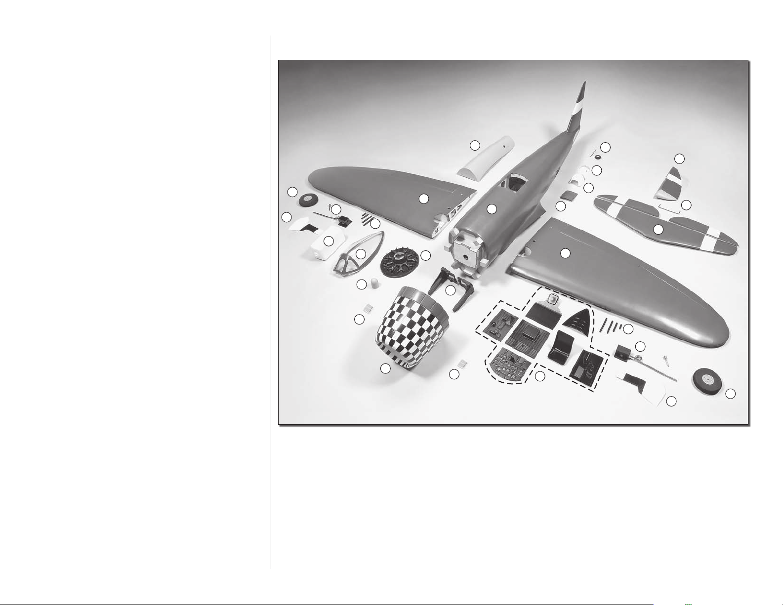
KIT INSPECTION
KIT CONTENTS
6
10
11
9
22
12
7
2
1
13
17
2
14
4
15
16
21
3
Before starting to build, take an inventory of this kit
to make sure it is complete, and inspect the parts
to make sure they are of acceptable quality. If any
parts are missing or are not of acceptable quality, or if
you need assistance with assembly, contact Product
Support. When reporting defective or missing parts,
use the part names exactly as they are written in the
Kit Contents list.
Top Flite Product Support
3002 N Apollo Drive, Suite 1
Champaign, IL 61822
Telephone: (217) 398-8970, ext. 5
Fax: (217) 398-7721
E-mail: airsupport@top-flite.com
19
18
5
1 - Fuselage
2 - Left and right wing panel
3 - Stabilizer with left and right elevator
4 - Rudder
5 - Cowl
6 - Belly pan
7 - Canopy
8 - Cockpit components
20
18
8
9 - Retractable landing gear and axle
10 - Wheels
11 - Landing gear doors
12 - Fuel tank
13 - Dummy engine
14 - Tail wheel
15 - Tail wheel cover
16 - Lower scoop
22
9
11
17 - Side scoops
18 - Forward scoops
19 - Spinner
20 - Engine mount
21 - Elevator joiner wire
22 - Machine guns
10
5
Page 6
ORDERING
Order
Number
Description
REPLACEMENT PARTS LIST
How to
purchase
Instruction manual
Missing pieces
Full-size plans
Wing Set
T/F P-47 ARF
TOPA1782
Fuselage
T/F P-47 ARF
TOPA1783
Tail Set
T/F P-47 ARF
TOPA1784
Cowl
T/F P-47 ARF
TOPA1785
Canopy
T/F P-47 ARF
TOPA1786
Decals
T/F P-47 ARF
TOPA1787
Dummy Engine
T/F P-47 ARF
TOPA1788
Wire Landing
Gear Set
T/F P-47 ARF
TOPA1789
Spinner
T/F P-47 ARF
TOPA1790
Gear Doors
T/F P-47 ARF
TOPA1791
Belly Pan
T/F P-47 ARF
TOPA1792
Contact
Product
Support
Not available
Contact
your
hobby
supplier
to
purchase
these
items
REPLACEMENT PARTS
Replacement parts for the Top Flite P-47 ARF are
available using the order numbers in the Replacement
Parts List that follows. The fastest, most economical
service can be provided by your hobby dealer or mailorder company.
PREPARATIONS
o 1. If you have not done so already, remove the
major parts of the kit from the box and inspect for
damage. If any parts are damaged or missing, contact
Product Support at the address or telephone number
listed in the Kit Inspection section on page 5.
To locate a hobby dealer, visit the Hobbico web site
at www.hobbico.com. Choose “Where to Buy” at
the bottom of the menu on the left side of the page.
Follow the instructions provided on the page to locate
a U.S., Canadian or International dealer. If a hobby
shop is not available, replacement parts may also be
ordered from Tower Hobbies
com, or by calling toll free (800) 637-6050.
Parts may also be ordered directly from Hobby
Services by calling (217) 398-0007, or via facsimile
at (217) 398-7721, but full retail prices and shipping
and handling charges will apply. Illinois and Nevada
residents will also be charged sales tax. If ordering
via fax, include a Visa
expiration date for payment.
Be certain to specify the order number exactly as
listed in the Replacement Parts List. Payment by
credit card or personal check only; no C.O.D.
If additional assistance is required for any reason
contact Product Support by e-mail at
Mail parts orders and
payments by personal
check to:
Hobby Services
3002 N Apollo Dr., Suite 1
Champaign IL 61822
productsupport@top-flite.com,
or by telephone at (217) 398-8970.
®
or MasterCard® number and
®
at www.towerhobbies.
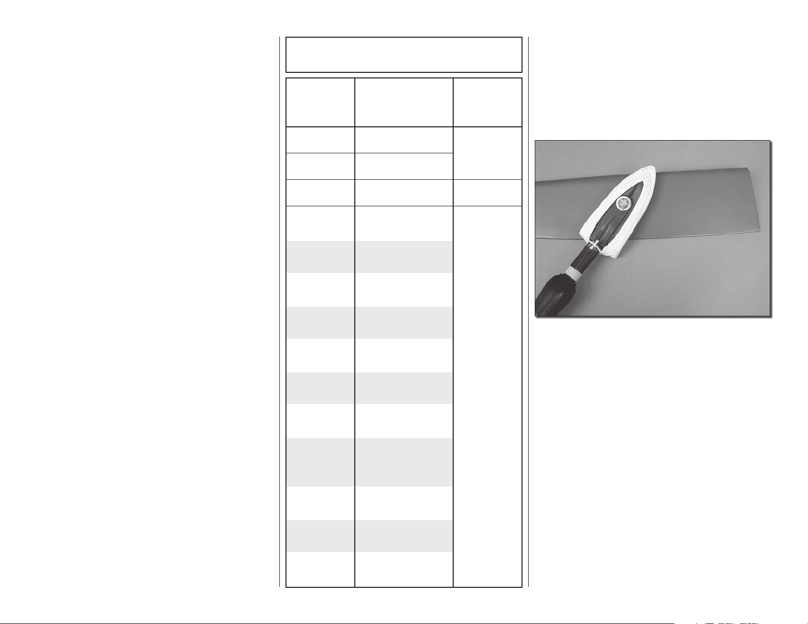
o 2. Use a covering iron with a covering sock on
high heat to tighten the covering if necessary. Apply
pressure over sheeted areas to thoroughly bond the
covering to the wood.
ASSEMBLE THE WING
MOUNT THE SERVOS
Before completing this section, confirm that the
servos that you will be using will properly fit between
the servo mounting block locations on the aileron
and flap servo hatch covers. Make adjustments
as necessary for your brand of servos. The block
locations shown in this section will fit a standard size
Futaba brand servo.
6
Page 7

to each hole to harden the wood. When the CA has
dried, install the servo onto the hatch cover using the
hardware supplied with the servo.
o o 1. Remove the tape holding the aileron and flap
covers to the wing. The servo mounting blocks are
pre-attached to the covers. To assure the blocks have
been adequately glued, apply a few drops of thin CA
to each of the blocks.
o o 2. Cut three arms from a four-armed servo arm
included with the aileron servo. Enlarge the outer hole
of the remaining arm with a 5/64" [2mm] drill bit.
o o 3. Attach a 24" [610mm] servo extension to
each aileron servo and secure the connector using
tape or heat shrink tubing (not included). Center the
servos with your radio system and install the servo
arm to the servo perpendicular to the servo case as
shown. Be sure to reinstall the servo arm screw into
the servo.
o o 4. Position the servo against the underside of
the aileron servo hatch cover between the mounting
blocks. Drill 1/16" [1.6mm] holes through the mounting
tabs on the servo case into the blocks. Insert and
then remove a servo mounting screw (included with
the servo) into each hole. Apply a drop of thin CA
7
o o 5. Tie the string taped inside the aileron servo
hatches to the servo lead. The opposite end of the
string is taped to the wing's root rib. Pull the servo
lead through the wing ribs.
o o 6. Insert and then remove a #2 x 3/8"
[9.5mm] self-tapping screw into each hatch
mounting hole. Apply a drop of thin CA to each
hole to harden the wood. Once the glue has dried,
install the aileron hatch cover to the wing as
shown using four #2 x 3/8" [9.5mm] self-tapping
screws and four #2 flat washers.
Page 8
o o 7. Mount the flap servo and hatch cover in the
same way. The flap servo does not require a servo
lead extension.
o 9. Repeat steps 1-9 for the left wing panel. Make
note that the flap servo arm will be mounted on the
root rib side of the right wing panel and the flap
servo arm is mounted towards the wing tip on the
left wing panel. When the flap servos are joined
together using a Y-harness, they will both move in
the same direction.
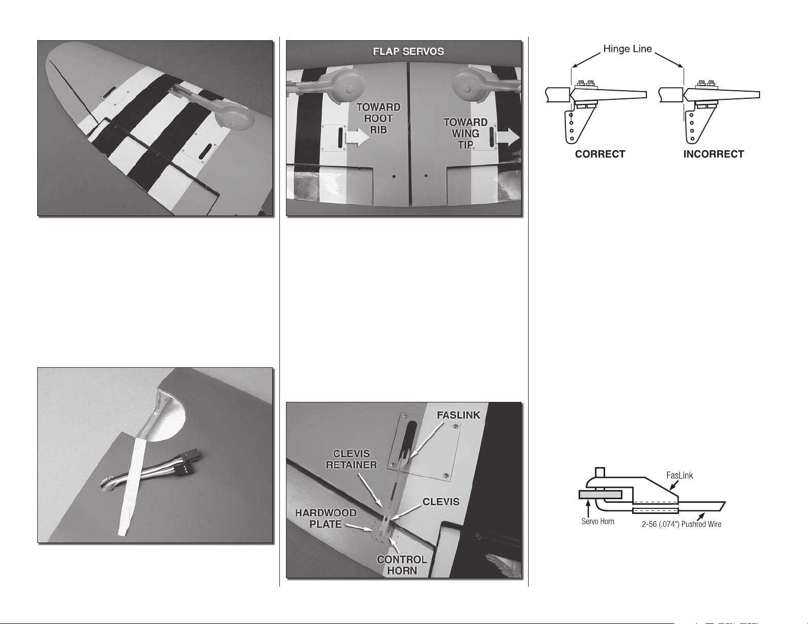
Refer to the photograph as you complete steps 1-4.
o o 1. Thread a nylon clevis 20 complete turns onto
a 4" [152mm] pushrod. Slide a silicone clevis retainer
onto the clevis and connect the clevis to the outer
hole of a nylon control horn.
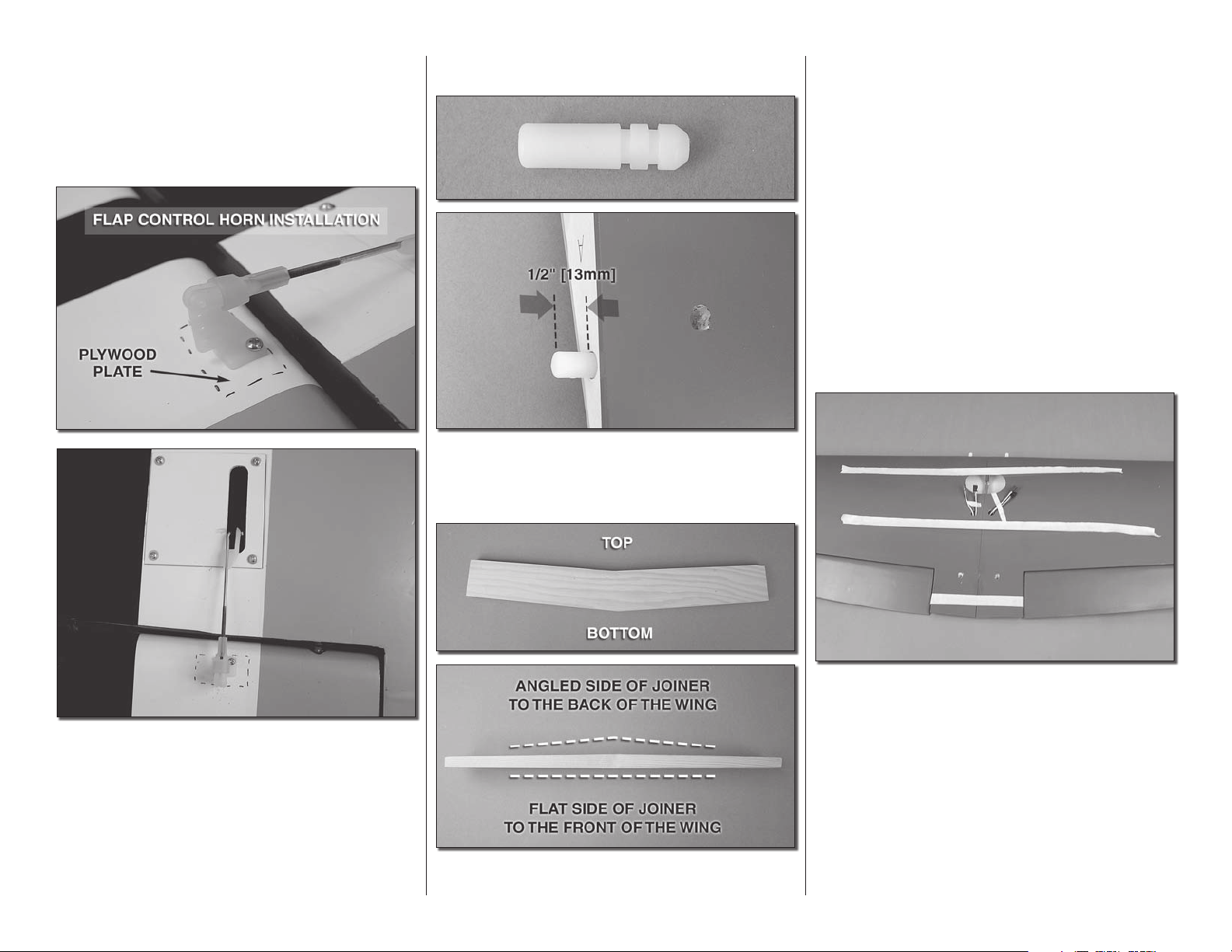
o o 2. Position the control horn over the plywood
plate in the aileron (if you cannot see it, hold the aileron
at a shallow angle in good lighting or use a small pin
to puncture the covering) using the position of the
servo arm as a guide. Align the holes in the control
horn directly over the aileron hinge line and mark the
location of the control horn mounting holes.
o o 8. Insert the servo leads through the hole in the
top of the wing. Tape the leads to the wing to prevent
them from dropping back in.
INSTALL THE AILERON AND FLAP PUSHRODS
8
o o 3. Drill 1/16" [1.6mm] holes at the marks you
made through the plywood plate. Do not drill all
the way through the aileron! Thread a #2 x 3/8"
[9.5mm] self-tapping screw through each hole and
back it out. Apply a couple drops of thin CA glue to
each hole to harden the wood. When the glue has
dried, install the control horns onto the aileron using
two #2 x 3/8" [9.5mm] self-tapping screws.
o o 4. Use tape or a small clamp to hold the aileron
in the neutral position. Make a mark on the pushrod
where it crosses the outer hole in the servo arm.
Make a 90 degree bend at the mark on the pushrod
Page 9
and cut off the excess pushrod 1/4" [6mm] beyond
the bend. Attach the pushrod to the servo arm using
a nylon FasLink. Thread the clevis up or down on the
pushrod as necessary to center the aileron with the
servo arm centered. Slide the silicone clevis retainer
to the end of the clevis to secure it.
JOIN THE WING PANELS
o 1. Locate the nylon anti-rotation pin. Epoxy it
into the hole in the right wing panel. Approximately
½"[13mm] of the pin should extend from the wing
the top of the joiner and the front of the joiner. Test fit
the joiner into the joiner pocket of each wing panel.
The joiner should be able to fit halfway into each
pocket and be slightly loose to allow room for epoxy.
Sand the joiner as necessary for the proper fit.
o 3. Dry fit the wing panels together using the joiner.
The root ribs of the panels should sit flat against each
other with no gaps. Lightly sand the face of the root
ribs if necessary to eliminate any gaps between the
wing panels.
o o 5. Install the flap pushrod using the same
procedure used for the aileron. The flap pushrod is
installed in the same manner except the control horn
is mounted as shown in the photograph, and rather
than centering the servo arm, position the servo arm
so that it is angled back towards the trailing edge of
the wing.
o 6. Repeat steps 1-5 for the other wing panel.
o 2. Locate the hardwood wing joiner. The joiner
has a double taper. The photo shows how to identify
9
o 4. When satisfied with the fit of the wing panels
mix up a ½ ounce of 30-minute epoxy and coat the
inside of the wing joiner pockets in each wing panel.
Coat one half of the wing joiner and slide it into one
wing panel. Coat the root ribs of both wing panels
as well as the exposed ends of the joiner and antirotation pin. Join the two wing panels together and
use paper towels dampened with denatured alcohol
to wipe away any excess epoxy from the joint
between the panels. Use masking tape to hold the
panels together tightly. Set the wing aside and let
the epoxy cure undisturbed.
Page 10
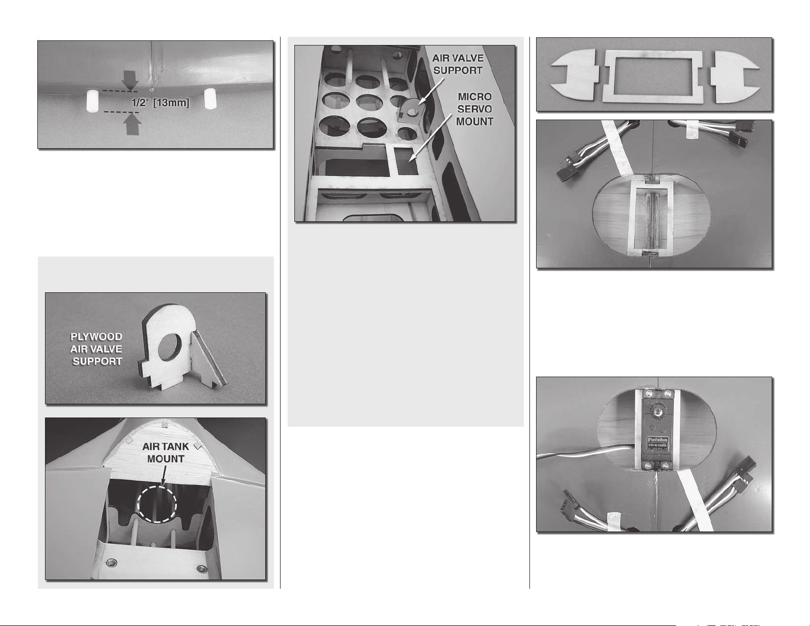
o 5. Glue two nylon pins into the holes in the leading
edge, at the center of the wing. Approximately
½"[13mm] should extend from the leading edge of
the wing.
INSTALL THE RETRACTABLE LANDING
GEAR, SERVO, WHEELS AND GEAR DOORS
Optional Pneumatic Retracts
Some modelers may wish to install pneumatic
retracts instead of the mechanical retracts included
in this kit. Mounting locations are provided in the
fuselage for optional pneumatic retract hardware
including the air tank, air valve, and air valve
servo. Tabs are designed into the air tank that
support the front of the air tank for securing it with
rubber bands. Detailed installation instructions
are not provided for installing pneumatic retracts.
However, the installation process for the gear is
similar to the mechanical installation shown in
the following instructions. The mechanical retract
pushrods will need to be replaced with air lines.
Be sure to follow the instructions included with
the pneumatic retract kit.
o 1. Locate the 3 plywood parts that make up the
servo tray. Test fit them into the center of the wing.
Adjust the parts as needed. Once you are satisfied
with the fit, glue the components in place. You will find
it easiest to glue each of the components in place
individually rather than gluing it together and then
trying to fit it into the opening.
10
2. Install your retract servo between the mounting rail
in the wing center section using the hardware that
came with the servo. Be sure to harden the screw
holes with thin CA glue.
Page 11
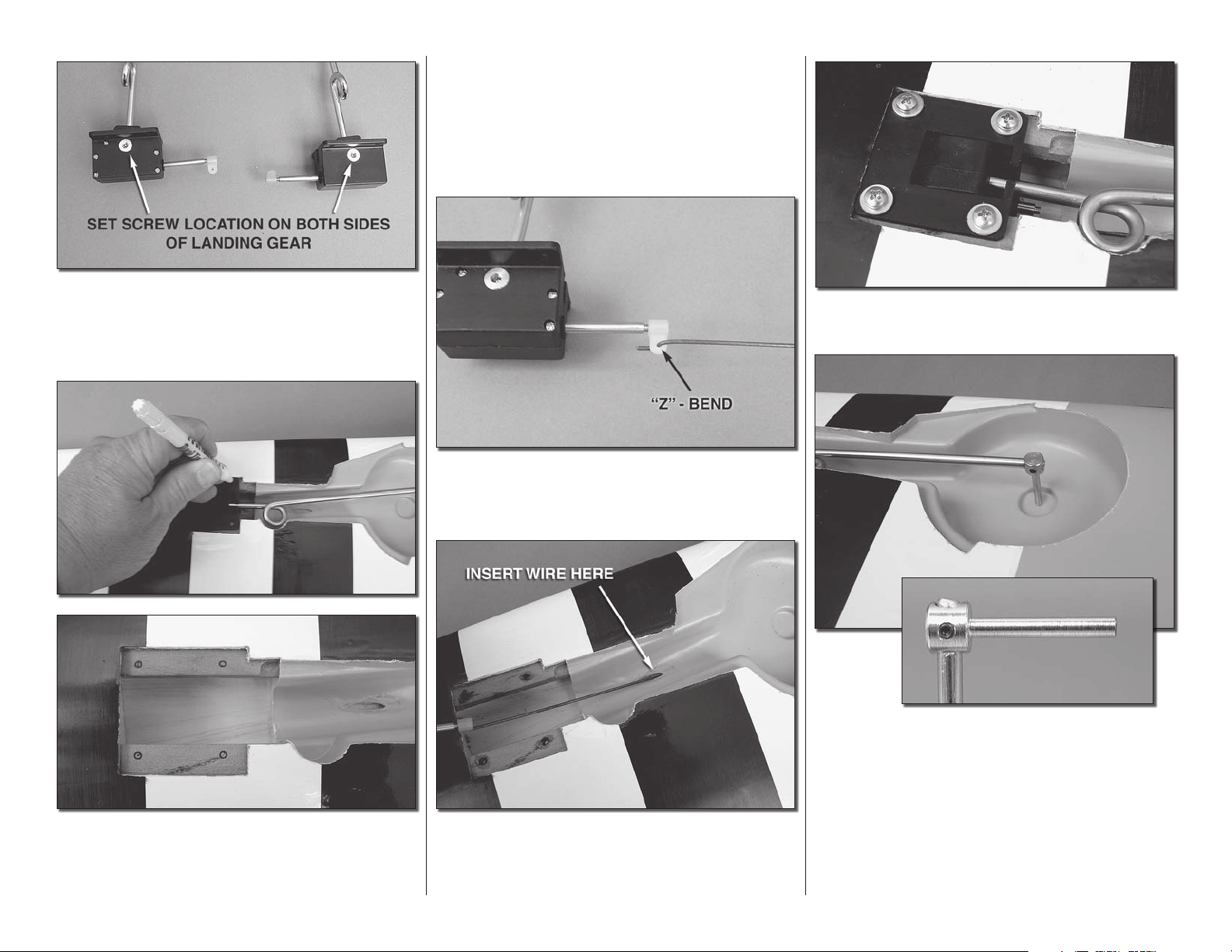
o o 3. Remove the set screw from each side of the
landing gear. Apply a couple of drops of thread locker
onto the set screws. Then re-insert it and tighten it
against the landing gear wire. Do this for both gear.
o o 5. On the marks you made for the location of
the landing gear drill a 7/64" [2.8mm] hole through
the rails. Insert and remove a #6 x3/4" [19mm] screw
into each of the holes. Apply a couple drops of thin
CA into the holes to harden the threads. Allow the
glue to harden.
o o 8. Mount the landing gear to the rail with four
#6 x ¾" [19mm] screws and four #6 flat washers.
o o 6. Locate one of the 12" [305mm] wires with the
“Z” bend on the end. Insert the end with the “Z” bend
into the connector on the end of the retract unit.
o o 4. Position the landing gear onto the landing
gear rails as shown here. With a pencil or fine tip
marker, mark the location of the holes for mounting
the landing gear.
o o 7. Insert the wire from the landing gear into the
tube located in the wheel well. Using the tube as a
guide, push the wire into the wing until the landing
gear can rest on the landing gear rails.
11
o o 9. Apply a drop of thread locker to two 3mm
set screws. Then, thread them into the axle (the set
screws may already be installed in the axle. If so
remove them, apply thread locker, and then re-install
them into the axle). Slide the axle onto the landing
gear. Tighten the set screws in the axle against the flat
spots that have been cut into the end of the landing
gear. When the axle is properly installed, the end of
the axle will fit into the wheel well as shown.
Page 12

o o 10. Using a motor tool or file, grind a flat spot
on the end of the axle.
o o 12. Apply a piece of masking tape to the surface
of the wing at each end of the landing gear. You need
to transfer the exact center line of the landing gear to
the tape. Draw a line on the tape that is directly down
the center of the landing gear wire.
o o 14. Apply another piece of masking tape to
the door in line with the landing gear wire. Using the
lines you previously drew at each end of the landing
gear, draw a line on the tape you just applied to the
door. This line represents the center of the landing
gear wire. From the center of the axle measure up
2-1/8" [54mm] and draw a line perpendicular to
the line representing the landing gear wire. From
that line measure up another 2" [51mm] and make
another line.
o o 11. Install the wheel onto the axle. Apply thread
locker to the set screw and tighten the set screw
against the flat spot on the axle.
o o 13. Tape the landing gear door onto the landing
gear. Be sure to center the door in the opening,
leaving an equal spacing between the door and the
opening on both the leading edge and trailing edge
of the door.
12
Page 13

o o 15. Place one of the nylon humped landing
gear straps on the line you have drawn. Pay careful
attention, positioning it so the hump is centered on
the line representing the landing gear wire and the
mounting holes are on the crossing line. When you are
satisfied with the position, mark the hole locations
of the strap onto the line. Do this for both lines you
have drawn.
o o 17. Attach the door to the landing gear wire
with two humped landing gear straps, four 2-56 x 3/8"
[10mm] screws and four #2 nuts. Be sure to apply
thread locker to the screws. You may wish to apply a
drop of paint to the screw heads to make them blend
into the door.
o 19. Cut four arms from a six-arm servo arm,
leaving two arms opposite each other. Attach a brass
screw-lock connector to each arm in the outer hole
using a nylon retainer to secure them. Loosely thread
a 4-40 x 1/8" [3.2mm] SHCS into each screw-lock
connector. Bend the retract wire as shown to allow
the wire to be aligned with the hole in the brass screw
lock connector. Slide the retract pushrod wires through
the screw-lock connectors and press the arm onto the
servo spline in the orientation shown. With the retract
pushrods all the way in the retracted position, tighten
the SHCS in the screw-lock connectors against the
pushrods. Remember to apply a drop of threadlocker
to the SHCS. Test the operation of the landing gear
with your radio system. Confirm that the servo does
not bind and that the landing gear fully raise and
lower to the locked positions. Make any adjustments
necessary with the screw-lock connectors and servo
arm position. When satisfied, secure the servo arm
to the servo using the servo arm screw included with
the servo.
o o 16. On each of the four marks drill a
3/32"[2.5mm] hole through the landing gear door.
o 18. Repeat steps 3-17 for the left wing.
13
Page 14

FINISH THE WING
o 1. Locate the fiberglass belly pan. Sand the
painted edge with 220-grit sandpaper and clean the
surface with alcohol.
HOW TO CUT COVERING FROM BALSA
Use a soldering iron to cut the covering from the
stab. The tip of the soldering iron doesn’t have to
be sharp, but a fine tip does work best. Allow the
iron to heat fully. Use a straightedge to guide the
soldering iron at a rate that will just melt the covering and not burn into the wood. The hotter the
soldering iron, the faster it must travel to melt a
fine cut. Peel off the covering.
o 4. There are two sets of black tubes that will be
installed as machine guns in the leading edge of the
wing. The holes for the guns are pre-drilled to the
correct depth for each of the guns. The tubes are
installed so the longest gun is towards the center of
the wing and the shortest is towards the tip. Test fit
a tube into each of the holes. Once you are satisfied
with the fit, glue the machine guns into the holes in
the leading edge of the wing.
o 2. Temporarily install the wing onto the fuselage
using two 1/4-20 nylon wing bolts. The wing dowels
will fit into receiving holes in the former at the leading
edge of the wing. Align the fiberglass belly pan onto
the underside of the wing in line with the fuselage
and tape it into position. Use a felt-tip pen to trace
around the belly pan onto the wing. Remove the belly
pan and trim a 3/8" [10mm] strip of covering from the
underside of the wing just inside the line you drew.
Be careful to cut only the covering and not the
surface of the wing. Use a sharp hobby knife or the
“ Hot Tip” that follows.
o 3. Glue the belly pan to the wing with epoxy. Tape
the belly pan in place and put some weight on it to
hold it in place while the glue dries.
14
Built in greater quantities than any other US fighter,
the P-47 was the heaviest single-engine WWII
fighter to go into production and the first pistonpowered fighter to exceed 500 mph. The Thunderbolt
performed 546,000 combat sorties between March
of 1943 and August 1945 and is considered the real
forerunner of today’s multirole fighters.
Page 15

ASSEMBLE THE FUSELAGE
INSTALL THE HORIZONTAL STABILIZER,
ELEVATORS AND RUDDER
For the installation of the stabilizer you will need
to have rubbing alcohol on hand for clean up.
If you do not have any, DO NOT START THIS
INSTALLATION UNTIL YOU DO!
It is suggested that you read the next few steps
to better understand the process before actually
gluing components in place.
o 1. Temporarily attach the wing to the fuselage with
two ¼ - 20 nylon wing bolts. Slide the horizontal
stabilizer in place in the back of the fuselage. Position
the stab so that it is equal in length on both sides of
the fuselage and that the distance from the wing tip
to the stabilizer tip is equal.
o 2. When you are satisfied with the positioning,
mark the outline of the fuselage onto the top and the
bottom of the stabilizer with a fine point felt-tip pen.
o 3. Inside of the line you have marked, cut the
covering from the top and bottom of the stabilizer
using the same technique used on the bottom of the
wing. Make sure you cut the covering only!
o 4. Locate the elevator joiner wire, and insert it
into the slots in the stab opening. Then insert the stab
into the opening in the rear of the fuselage.
15
o 5. Stand back a few feet and look at the stab in
relation to the wing. The stab should be parallel and
in line with the wing. If you find that your stab is not
aligned, adjust the stab by removing small amounts
of the stab saddle with 100 grit sand-paper.
o 6. Move the stab to the right and left, exposing the
wood where you cut the covering away. Apply 30-minute
epoxy to the wood on both the top and bottom of the
stab. Work the glue into the stab opening by moving
the stab back and forth. When you are satisfied with the
penetration of the glue, clean away the excess epoxy
from the stab and fuselage using a cloth dampened
with alcohol. Once cleaned, double check the stab
position and check to be sure the elevator joiner wire
moves freely. Set it aside to cure.
Page 16

o 7. Cut the included CA hinge material into six 3/4"
x 1" [19mm x 25mm] individual hinges. Use a hobby
knife or scissors to trim the corners from each hinge
to make them easier to insert into the hinge slots.
o 8. Drill a 3/32" [2.4mm] hole 1/2" [13mm] deep in
the center of each hinge slot in the wing panel and
aileron. Use a sharp hobby knife to carefully cut away
the covering just around each hinge slot.
o 9. Insert three hinges into each elevator. If the
hinges don’t remain centered, stick a pin through the
middle of the hinge to hold it in position. Slide the
hinges into the elevator, sliding the joiner wire into the
hole in the elevator. Once you are satisfied everything
fits, remove the elevator.
16
o 10. Apply a small amount of epoxy into the hole in
each elevator half. Re-install the elevators and hinges
to the stab. Remove any pins you may have inserted
into the hinges. Adjust the elevator so there is a small
gap between the LE of the elevator and the stab. The
gap should be small, just enough to see light through
or to slip a piece of paper through. Apply six drops of
thin CA to the top and bottom of each hinge. Do not
use CA accelerator. After the CA has fully hardened,
test the hinges by pulling on the elevator. Do this for
both elevator halves.
Page 17

system and install the servo arm perpendicular to
the servo case as shown. Install the servos using the
same procedure used for the other servos, mounting
them onto the servo rails. Be sure to harden the screw
holes with thin CA.
o 11. Install three hinges into the rudder the same
as done with the elevator. Test fit the rudder to the
fin. When you are satisfied with the final fit, apply six
drops of thin CA to the top and bottom of each hinge.
o 12. Screw a nylon clevis onto a .074 x 36"
[914mm] threaded wire 20 turns. Slide a nylon clevis
retainer onto the clevis. Slide the pushrod wire into
the pushrod guide tube hole on the right side of the
fuselage. Install the clevis into the outer hole of the
control horn. Then, slide the silicone retainer over
the clevis. Mark the location for the control horn
onto the elevator. Drill a 1/16" [1.6mm] hole into the
plywood plate in the elevator. Do not drill through
the elevator. Screw the horn to the rudder with #2 x
3/8" [10mm] screws. Remove the screws, and apply
a drop of thin CA to harden the threads. After the glue
has dried, re-install the screws into the horn.
o 13. Repeat step 14 for the rudder. The pushrod
wire will slide into the pushrod guide tube on the left
side of the fuselage.
INSTALL THE SERVOS, ENGINE
AND FUEL TANK
We will be showing the installation of the O.S. .91
engine. If you are installing a larger four-stroke
engine or a two stroke engine, you may need to
make additional cut outs in the cowl or the fuselage
to accommodate the cylinder head and the muffler.
o 1. Use the wire pushrods as your guide for
positioning the servos. Cut three arms from a fourarmed servo arm. Center the servo with your radio
17
o 2. Bolt the engine mount to the firewall with
four 8-32 x 1" [25mm] socket head cap screw, #8
lock washer and #8 flat washer. The engine will be
mounted inverted so be sure the mount is attached to
the firewall inverted. Place your engine on the mount
and adjust the mounting rail position to match and
then tighten the bolts.
o 3. Position the engine on the mount so the
distance from the firewall to the front of the thrust
washer measures 6-1/8" [155mm]. Mark the location
Page 18

of the engine on the mount. The Great Planes® “Dead
Center” Hole Locator (GPMR8130) works well for
this. Drill through the marks you have made with a
#29 or 9/64" [3.6mm] drill bit. Tap each hole with an
8-32 tap.
Remove screws to
rotate carburetor
Correct position
for throttle arm
o 4. Before installing the engine to the mount, check
the location of the throttle arm. Looking from the back
of the engine, the arm needs to be on the left side.
The O.S. engines allow you to rotate the carburetor.
Remove the two screws holding the carburetor to the
engine. Remove the carburetor, rotate it 180 degrees,
and then re-install the screws. Engines other than O.S.
may or may not allow you to rotate the carburetor. If
you cannot, you will have to position the throttle servo
in a different location than you will be instructed later
in this manual.
o 6. Install a brass screw lock connector to the outer
hole of the throttle arm. Lock it to the arm with a nylon
retainer. Slide a pushrod wire through the connector,
touching it to the firewall. Make a mark where the wire
will pass through the firewall.
o 7. Drill a 3/16" [4.8mm] hole on the mark. Glue a
12" [305mm] plastic tube into the hole.
o 9. Slide the wire from the throttle into the brass
screw lock connector. Lock the wire to the connector
with a 4-40 x 1/8" [3mm] socket head cap screw. For
the rudder and elevator, center the control surfaces.
Make a mark on the pushrod where it crosses the
outer hole in the servo arm. Make a 90 degree bend
at the mark on the pushrod and cut off the excess
pushrod 1/4" [6mm] beyond the bend. Attach the
pushrod to the servo arm using a nylon FasLink.
Make sure all of the servo horn screws are installed
in the servos.
o 5. Install the engine to the mount with four each,
8-32 x 1" [25mm] socket head cap screws, #8 lock
washers and #8 flat washers.
o 8. Remove the servo arm from the rudder. Install
a ball link into the second hole from the center. Lock
it to the servo horn with the 0-80 nut. Re-install the
horn to the servo.
18
o 10. Bend the throttle pushrod slightly to get a
smooth movement of the pushrod wire and then
secure the wire with a 4-40 x 1/8" [3mm] socket head
cap screw. Be sure to apply threadlocker to the bolt.
Page 19

o 11. Assemble the fuel tank as shown in the
sketch. When tightening the center screw be sure not
to over tighten it. You just want it snug enough to pull
the rubber stopper tight against the tank.
o 13. Install silicone fuel tubing (not supplied) onto
the aluminum tubes from the fuel tank. One line with
the fuel clunk will feed to the fuel inlet at the needle
valve. The second line with the fuel clunk will be the
line to fill the tank and the other will attach to the
pressure tap on the muffler. (The muffler will not be
installed at this time. You will do this while fitting the
cowl.) The fill line should be plugged after fueling with
the aluminum fuel plug provided with the kit.
INSTALL THE TAIL WHEEL AND LINKAGES
the flat spot in the wire. Be sure that the steering
arm is oriented in the same direction as shown in
the picture. Slide the nylon support onto the wire
beneath the steering arm. Tighten a 1/8" [3.2mm]
wheel collar using a 4-40 set screw onto the wire
below the nylon support. The support should still be
able to rotate on the wire. Secure a brass screwlock connector to the linkage hole in the steering
arm with a nylon retainer. Loosely thread a 4-40
set screw into the screw-lock connector. Be sure to
apply thread locker to all of the screws.
o 12. Slide the neck of the fuel tank into the hole in
the firewall and rest the tank on the tray. Secure the
tank to the tray with two #64 rubber bands.
o 1. Locate the pieces for the tail wheel assembly.
Loosely thread the 3x5mm SHCS into the collar
hole in the steering arm. Slide the steering arm onto
the tail wheel wire and tighten the SHCS against
19
o 2. Secure the assembly with two #2 x 3/8" [9.5mm]
self-tapping screws.
Page 20

o 4. Center the tail wheel wire axle and tighten the
set screw in the screw-lock connector against the tail
wheel pushrod.
INSTALL THE RADIO SYSTEM
o 3. Thread a nylon ball cup onto the end of a 2-56
x 36" [914mm] pushrod threaded on one end. Cut
the wire to a length of 27-3/4" [705mm]. Insert the
pushrod into the pushrod tube that is closest to the
bottom of the fuse. Feed the aft end of the pushrod
through the brass screw lock connector on the tail
wire steering arm and out the elevator control horn
access hole. Push the ball cup onto the ball stud.
o 5. Fit the tail wheel hatch cover in place and
secure it with four #2 x 3/8" [9.5mm] screws. Be sure
to harden the screw holes with thin CA.
o 6. Install the tail wheel onto the tail wheel axle
using two 1/8" [3.2mm] wheel collars and two 4-40
set screws. Be sure that the wheel rotates on the axle
freely. Oil the axle if necessary.
20
o 1. Locate the plywood battery / receiver tray.
Loop one of the Velcro straps through the slots in the
ends of the tray. Place a piece of foam between the
tray and your receiver battery. Secure the battery to
the tray with the Velcro.
o 2. Slide the remaining Velcro through the other two
slots in the tray, wrapping them around the top.
Page 21

o 3. Install your radio switch and charge jack. Ours was
mounted on the side of the fuselage. Plug the battery
lead into the charge jack. Secure the connection with
heat shrink tubing, tape or some similar method to be
sure the lead does not come unplugged.
o 4. Place the tray into the fuselage and onto the
hardwood rails between the servo tray and the fuel
tank. When installing the tray the battery should
be towards the inside of the fuselage. Drill a 1/16"
[1.6mm] hole through the mounting holes. Secure
the tray with two #2 x 3/8" [10mm] screws and two
#2 flat washers.
o 5. Plug the lead from the switch into the receiver.
Place a piece of foam between the tray and the
receiver and the secure the receiver to the tray with
the Velcro.
o 6. Route the receiver antenna through the fuselage
to the antenna tube located between the pushrod
guide tubes.
21
o 7. Install a 6" [152mm] servo extension into the
flap, aileron and retractable landing gear channels
of the receiver. Plug the elevator, rudder and throttle
servos into the receiver. Pay careful attention, routing
the wires to assure a clean installation.
o 8. Plug the two flap servos and the two
aileron servos in the wing into “Y” harnesses.
Secure the servos to the “Y” harness with shrink
tubing, tape or some other method to keep them
from coming unplugged.
o 9. With your radio system turned on, adjust the
position of all of the servo arms and linkages until all
of the control surfaces are neutral.
P-47s flew more than 546,000 combat sorties
between March 1943 and August 1945, destroying
11,874 enemy aircraft, some 9,000 locomotives,
and about 6,000 armored vehicles and tanks. Only
0.7 per cent of the fighters of this type dispatched
against the enemy were lost in combat. As a
testament to the survivability of the P-47, it should
be noted that the top ten aces who flew the P-47
returned home safely.
Page 22

FINISH THE MODEL
the backside of the dummy engine where the tube
contacts the plastic to keep them in place.
INSTALL THE COWL & DUMMY ENGINE
Before installing the cowl you must give some
consideration to the mufflers. If you have installed
a two-stroke engine you will need to cut a lot of the
cowl for the standard muffler. A “Pitts” style muffler
will help minimize the amount of the cowl you will
need to cut. The four-stroke muffler fits pretty well
but a better fit can be achieved if you utilize the
additional exhaust header that will be mentioned.
We are showing the installation of the O.S. .91 fourstroke engine. Modify the instructions as needed to
fit your particular engine.
o 4. Cut the 12" [305mm] red wire into nine 1-3/8"
[35mm] lengths.
o 2. Drill 1/8" [3mm] holes into each of the cylinder
heads and at the base of the cylinder as shown.
o 5. Drill a 1/16" [1.6mm] hole into the cylinder and
at the base of the cylinder. Install a red wire into the
holes to replicate the spark plug lead. Secure the
wire with glue on the back side of the dummy engine
in the same way it was done for the tubes.
o 1. Cut away the portion of the dummy engine that
will be in front of the engine cylinder. This is needed
for proper cooling of the engine. When determining
the exact location to cut, note that the cylinders
should be oriented as shown in the picture. We were
able to cool the O.S. .91 by only cutting away a small
portion of the vacuum formed engine as shown in
the picture.
o 3. Install one of the 1/8" aluminum tubes into
each of the sets of holes. Apply a drop of glue on
22
Page 23

o 6. Tack glue the dummy engine into the cowl. Place
the cowl onto the fuselage and make sure it centers
with the engine crankshaft. Adjust the dummy engine
as needed. Pay careful attention to the clearance
of the dummy cylinder where it sits in front of the
engine. You may need to remove additional material
from the back of the dummy engine to get clearance
for the engine. Once you are satisfied with the fit,
permanently glue the dummy engine to the cowl. A
mixture of 6-minute epoxy and micro balloons works
well for this.
clears the engine. If necessary trim the dummy
engine to get clearance for the engine. Center the
cowl on the engine and slide it back onto the fuselage
and the cowl mounting blocks.
about the washers now.) Do this for each of the five
remaining mounting blocks. Check the position of the
cowl each time before you drill.
o 9. After you have installed the cowl, remove the
cowl. Apply a couple drops of thin CA into the holes
to harden the threads.
o 10. For our installation we used a 90 degree
exhaust header (OSMG2624) in conjunction with
the stock muffler. This allows you to divert the
muffler under the fuselage rather than out the side
of the cowl.
o 7. Position the cowl over the engine and onto the
fuselage. Check to make sure the dummy engine
o 8. From behind the cowl, the cowl mounting blocks
are visible. With the cowl properly positioned, drill a
1/16" [1.6mm] hole through the cowl and into one
mounting block. The hole should be approximately
½" [13mm] back from the trailing edge of the cowl.
Install a #2 x 3/8" [10mm] screw to hold the cowl in
place. (When you are mounting the cowl, #2 washers
should also be used. But since we will be removing
and installing the cowl several times, don’t worry
23
o 11. Assemble the muffler and header to position
the muffler where you want it to exit the cowl. Be
sure to use thread locker to assure everything stays
tight. When you are satisfied, install the pressure
line to the muffler.
Page 24

o 13. Finish cutting any additional openings in the
cowl. The needle valve will most likely require an
extension to make adjustments from outside of the
cowl. See your engine manufacturer’s manual for
additional information.
INSTALL THE SCALE DETAILS
For all of the detail pieces it is important that you
lightly scuff the back side of the plastic with 220-grit
sandpaper to get good adhesion.
o 1. Glue the air exhaust panels facing rearward
as shown. Carefully remove 1/16" [1.6mm] of
covering from around the opening using the same
technique used earlier. Removing the covering will
provide a better glue bond. Do this for both sides
of the fuselage.
o 12. Carefully cut the cowl to allow it to fit around the
muffler. You may be tempted to keep the opening in
the bottom of the cowl as small as possible by using a
remote starter. Please keep in mind that you do have
to have some area for the air to escape the cowl. If
you do not, you will most likely experience engine
overheating. Cutting the cowl as shown, we had no
overheating issues and there was adequate room for
the glow driver. Regardless of your engine choice,
you must leave an area for exit air of at least 6 square
inches [39 square centimeters]. The area around the
cowl is not sufficient for adequate cooling.
o 2. Mark the location for the forward exhaust
scoops. Cut a small amount of covering away from
the fuselage and then glue the scoops in place.
24
Page 25

suggested that you glue this directly to the covering
with 6-minute epoxy. In our testing this held very well.
Mix a small amount of epoxy and tape the scoop in
place. Clean up any glue residue with alcohol.
INSTALL THE COCKPIT INTERIOR,
PILOT AND CANOPY
o 2. If you will be installing a pilot he will be glued
to the seat. To be sure the weight of the pilot coupled
with stresses in flight does not cause the seat to
come loose, it is recommended that you glue a 1"
[25mm] square piece of plywood (not included) under
the riser on the floor. This will allow you to glue and
screw the seat in place.
o 3. Test fit the interior to the fuselage. Install the
back/head rest first followed by the floor, instrument
panel and side panels. Trim as needed to get a
good fit.
o 3. Mark the location for the bottom scoop. This is
in the center of the fuselage and should be aligned
with the black and white stripes. This scoop does
not have a lot of gluing area, making it difficult to
cut enough covering away to make a difference. It is
o 1. The cockpit is made up of the floor, two side
panels, instrument panel, back/head rest and the
seat. The components are pre-painted but scale
minded modelers may wish to add additional detail
and color to their cockpit. Now is a good time to make
these additions.
25
o 4. Epoxy the seat in place. When the glue has
cured, drill two 1/16" [1.6mm] holes through the seat
and into the plywood. Screw the seat in place with #2
x 3/8" [10mm] screws and #2 flat washers.
Page 26

o 5. Glue all of the components into the fuselage.
Install the back/head rest first followed by the floor,
instrument panel and side panels. Note: The side
panel with the throttle quadrant goes on the left side.
of the body to fit the full body pilot. This may make
you consider using the bust only. (CJMQ 9036) Both
versions require minor assembly and are unpainted.
If you are installing a pilot glue him in place now. If
you will be doing this later, skip installing the canopy
until you have the pilot completed.
o 8. Glue the canopy to the covering with Super Z
RC56 canopy glue. Tape the canopy in place until the
glue dries.
o 6. Glue the back deck behind to the top of the
fuselage behind the cockpit area.
o 7. We have found that the 1/7th scale WWII
American Pilot bust from Century Jet Models works
well in this model. They offer both a full body (CJMQ
9038) and a bust. You will have to cut away some
26
INSTALL THE PROPELLER AND SPINNER
o 1. The spinner included with this kit can be
tightened against the propeller without the use of a
drive washer.
Page 27

APPLY THE DECALS
We have included three different trim schemes for this
model, giving you some flexibility in the final look of
the model. Please refer to the sketches on this page
for the placement of the major decals.
1. Use scissors or a sharp hobby knife to cut the
decals from the sheet.
2. Be certain the model is clean and free from oily
fingerprints and dust. Prepare a dishpan or small
bucket with a mixture of liquid dish soap and warm
water—about one teaspoon of soap per gallon of
water. Submerse the decal in the soap and water
and peel off the paper backing. Note: Even though
the decals have a “sticky-back” and are not the
water transfer type, submersing them in soap &
water allows accurate positioning and reduces air
bubbles underneath.
Trim Scheme 1 Trim Scheme 3
Trim Scheme 2
3. Position the decal on the model where desired.
Holding the decal down, use a paper towel to wipe
most of the water away.
4. Use a piece of soft balsa or something similar to
squeegee remaining water from under the decal.
Apply the rest of the decals the same way.
Before the war was over, a total of 15,579
Thunderbolts were built, about two-thirds of which
reached operational squadrons overseas.
27
Page 28

GET THE MODEL READY TO FLY
FULL
THROTTLE
RUDDER
MOVES
RIGHT
ELEVATOR
MOVES DOWN
RIGHT AILERON
MOVES UP
LEFT AILERON
MOVES DOWN
4-CHANNEL RADIO SETUP
(STANDARD MODE 2)
These are the recommended
control surface throws:
ELEVATOR
HIGH RATE
FULL
ONE
HALF
LOW RATE
1/2"
[13mm]
11°
Up
1/2"
[13mm]
11°
Down
3/8"
[10mm]
10°
Up
3/8"
[10mm]
10°
Down
9/16"
[14mm]
16°
Up
9/16"
[14mm]
16°
Down
3/8"
[10mm]
11°
Up
3/8"
[10mm]
11°
Down
2"
[51mm]
36°
Down
7/8"
[22mm]
16°
Down
1-3/8"
[35mm]
21°
Right
1-3/8"
[35mm]
21°
Left
1"
[25mm]
15°
Right
1"
[25mm]
15°
Left
RUDDERAILERONSFLAPS
CHECK THE CONTROL DIRECTIONS
o 1. Turn on the transmitter and receiver and center
the trims. If necessary, remove the servo arms from
the servos and reposition them so they are centered.
Reinstall the screws that hold on the servo arms.
o 2. With the transmitter and receiver still on, check
all the control surfaces to see if they are centered.
If necessary, adjust the clevises on the pushrods to
center the control surfaces.
SET THE CONTROL THROWS
Use a Great Planes AccuThrow (or a ruler) to
accurately measure and set the control throw of each
control surface as indicated in the chart that follows. If
your radio does not have dual rates, we recommend
setting the throws at the low rate setting.
NOTE: The throws are measured at the widest part
of the elevators, rudder and ailerons.
Note: When flaps are deployed you can expect the
airplane to balloon slightly. To minimize this we mixed
1/32" [0.8mm] down elevator trim when the flaps were
deployed. If you have a flap to elevator mix you may
wish to consider this mix as well.
IMPORTANT: The P-47 ARF has been
extensively flown and tested to arrive at the
throws at which it flies best. Flying your model
at these throws will provide you with the greatest
chance for successful first flights. If, after you
have become accustomed to the way the P-47
flies, you would like to change the throws to suit
your taste, that is fine. However, too much control
throw could make the model difficult to control,
so remember, “more is not always better.”
o 3. Make certain that the control surfaces and
the carburetor respond in the correct direction as
shown in the diagram. If any of the controls respond
in the wrong direction, use the servo reversing in
the transmitter to reverse the servos connected to
those controls. Be certain the control surfaces have
remained centered. Adjust if necessary.
BALANCE THE MODEL (C.G.)
More than any other factor, the C.G. (balance
point) can have the greatest effect on how a model
flies, and may determine whether or not your first
flight will be successful. If you value this model
and wish to enjoy it for many flights, DO NOT
OVERLOOK THIS IMPORTANT PROCEDURE.
A model that is not properly balanced will be
unstable and possibly unflyable.
At this stage the model should be in ready-to-fly
condition with all of the systems in place including
the engine, landing gear, and the radio system.
o 1. Use a felt-tip pen or 1/8" [3mm]-wide tape to
accurately mark the C.G. on the top of the wing on
both sides of the fuselage. The C.G. is located 4-1/8"
[105mm] back from the leading edge of the wing
where it meets the fuse.
28
Page 29

This is where your model should balance for the
4 -1/8" [105 mm]
first flights. Later, you may wish to experiment by
shifting the C.G. up to 3/8" [10mm] forward or 3/8"
[10mm] back to change the flying characteristics.
Moving the C.G. forward may improve the
smoothness and stability, but the model may
then require more speed for takeoff and make
it more difficult to slow for landing. Moving the
C.G. aft makes the model more maneuverable,
but could also cause it to become too difficult to
control. In any case, start at the recommended
balance point and do not at any time balance
the model outside the specified range.
o 2. With the wing attached to the fuselage, all parts
of the model installed (ready to fly) and an empty
fuel tank, place the model upside-down on a Great
Planes CG Machine, or lift it upside-down at the
balance point you marked.
o 3. If the tail drops, the model is “tail heavy” and the
battery pack and/or receiver must be shifted forward
or weight must be added to the nose to balance. If
the nose drops, the model is “nose heavy” and the
battery pack and/or receiver must be shifted aft or
weight must be added to the tail to balance. If possible,
relocate the battery pack and receiver to minimize or
eliminate any additional ballast required. If additional
weight is required, nose weight may be easily added
by using a “spinner weight” (GPMQ4645 for the 1 oz.
[28g] weight, or GPMQ4646 for the 2 oz. [57g] weight).
If spinner weight is not practical or is not enough, use
Great Planes (GPMQ4485) “stick-on” lead. A good
place to add stick-on nose weight is to the firewall
(don’t attach weight to the cowl—it is not intended
to support weight). Begin by placing incrementally
increasing amounts of weight on the bottom of the
fuse over the firewall until the model balances. Once
you have determined the amount of weight required,
it can be permanently attached. If required, tail weight
may be added by cutting open the bottom of the fuse
and gluing it permanently inside.
Note: Do not rely upon the adhesive on the back of the
lead weight to permanently hold it in place. Over time,
fuel and exhaust residue may soften the adhesive
and cause the weight to fall off. Use #2 sheet metal
screws, RTV silicone or epoxy to permanently hold
the weight in place.
o 4. IMPORTANT: If you found it necessary to add
any weight, recheck the C.G. after the weight has
been installed.
BALANCE THE MODEL LATERALLY
o 1. With the wing level, have an assistant help you
lift the model by the engine propeller shaft and the
bottom of the fuse under the TE of the fin. Do this
several times.
o 2. If one wing always drops when you lift the model,
it means that side is heavy. Balance the airplane by
adding weight to the other wing tip. An airplane that
has been laterally balanced will track better in
loops and other maneuvers.
PREFLIGHT
IDENTIFY YOUR MODEL
No matter if you fly at an AMA sanctioned R/C club
site or if you fly somewhere on your own, you should
always have your name, address, telephone number
29
and AMA number on or inside your model. It is
required at all AMA R/C club flying sites and AMA
sanctioned flying events. Fill out the identification tag
on page 33 and place it on or inside your model.
CHARGE THE BATTERIES
Follow the battery charging instructions that came with
your radio control system to charge the batteries. You
should always charge your transmitter and receiver
batteries the night before you go flying, and at other
times as recommended by the radio manufacturer.
CAUTION: Unless the instructions that came
with your radio system state differently, the initial
charge on new transmitter and receiver batteries
should be done for 15 hours using the slow-
charger that came with the radio system.
This will “condition” the batteries so that the next
charge may be done using the fast-charger of
your choice. If the initial charge is done with a
fast-charger, the batteries may not reach their
full capacity and you may be flying with batteries
that are only partially charged.
BALANCE PROPELLERS
Carefully balance your propeller and spare
propellers before you fly. An unbalanced prop can
be the single most significant cause of vibration
that can damage your model. Not only will engine
Page 30

mounting screws and bolts loosen, possibly with
disastrous effect, but vibration may also damage
your radio receiver and battery. Vibration can also
cause your fuel to foam, which will, in turn, cause
your engine to run hot or quit.
We use a Top Flite Precision Magnetic Prop Balancer
(TOPQ5700) in the workshop and keep a Great
Planes Fingertip Prop Balancer (GPMQ5000) in our
flight box.
GROUND CHECK
If the engine is new, follow the engine
manufacturer’s instructions to break-in the
engine. After break-in, confirm that the engine idles
reliably, transitions smoothly and rapidly to full power
and maintains full power—indefinitely. After you run
the engine on the model, inspect the model closely
to make sure all screws remained tight, the hinges
are secure, the prop is secure and all pushrods and
connectors are secure.
RANGE CHECK
Ground check the operational range of your radio
before the first flight of the day. With the transmitter
antenna collapsed and the receiver and transmitter
on, you should be able to walk at least 100 feet
away from the model and still have control. Have an
assistant stand by your model and, while you work
the controls, tell you what the control surfaces are
doing. Repeat this test with the engine running at
various speeds with an assistant holding the model,
using hand signals to show you what is happening.
If the control surfaces do not respond correctly, do
not fly! Find and correct the problem first. Look for
loose servo connections or broken wires, corroded
wires on old servo connectors, poor solder joints in
your battery pack or a defective cell, or a damaged
receiver crystal from a previous crash.
ENGINE SAFETY PRECAUTIONS
Failure to follow these safety precautions
may result in severe injury to yourself
and others.
Keep all engine fuel in a safe place, away from high
heat, sparks or flames, as fuel is very flammable. Do
not smoke near the engine or fuel; and remember
that engine exhaust gives off a great deal of deadly
carbon monoxide. Therefore do not run the engine
in a closed room or garage.
Get help from an experienced pilot when learning to
operate engines.
Use safety glasses when starting or running engines.
Do not run the engine in an area of loose gravel or
sand; the propeller may throw such material in your
face or eyes.
Keep your face and body as well as all spectators
away from the plane of rotation of the propeller as
you start and run the engine.
Keep these items away from the prop: loose clothing,
shirt sleeves, ties, scarfs, long hair or loose objects
such as pencils or screwdrivers that may fall out of
shirt or jacket pockets into the prop.
Use a “chicken stick” or electric starter to start the
engine. Do not use your fingers to flip the propeller.
Make certain the glow plug clip or connector is secure
so that it will not pop off or otherwise get into the
running propeller.
Make all engine adjustments from behind the rotating
propeller.
The engine gets hot! Do not touch it during or right
after operation. Make sure fuel lines are in good
condition so fuel will not leak onto a hot engine,
causing a fire.
30
To stop a glow engine, cut off the fuel supply by closing
off the fuel line or following the engine manufacturer’s
recommendations. Do not use hands, fingers or any
other body part to try to stop the engine. To stop a
gasoline powered engine an on/off switch should be
connected to the engine coil. Do not throw anything
into the propeller of a running engine.
AMA SAFETY CODE (excerpts)
Read and abide by the following excerpts from the
Academy of Model Aeronautics Safety Code. For
the complete Safety Code refer to Model Aviation
magazine, the AMA web site or the Code that came
with your AMA license.
GENERAL
1) I will not fly my model aircraft in sanctioned events,
air shows, or model flying demonstrations until it
has been proven to be airworthy by having been
previously, successfully flight tested.
2) I will not fly my model aircraft higher than
approximately 400 feet within 3 miles of an airport
without notifying the airport operator. I will give rightof-way and avoid flying in the proximity of full-scale
aircraft. Where necessary, an observer shall be
utilized to supervise flying to avoid having models fly
in the proximity of full-scale aircraft.
3) Where established, I will abide by the safety rules
for the flying site I use, and I will not willfully and
deliberately fly my models in a careless, reckless
and/or dangerous manner.
5) I will not fly my model unless it is identified with
my name and address or AMA number, on or in the
model. Note: This does not apply to models while
being flown indoors.
7) I will not operate models with pyrotechnics (any
device that explodes, burns, or propels a projectile
of any kind).
Page 31

RADIO CONTROL
1) I will have completed a successful radio equipment
ground check before the first flight of a new or
repaired model.
2) I will not fly my model aircraft in the presence of
spectators until I become a qualified flier, unless
assisted by an experienced helper.
3) At all flying sites a straight or curved line(s) must
be established in front of which all flying takes place
with the other side for spectators. Only personnel
involved with flying the aircraft are allowed at or in
the front of the flight line. Intentional flying behind the
flight line is prohibited.
4) I will operate my model using only radio control
frequencies currently allowed by the Federal
Communications Commission.
5) I will not knowingly operate my model within
three miles of any pre-existing flying site except in
accordance with the frequency sharing agreement
listed [in the complete AMA Safety Code].
9) Under no circumstances may a pilot or other
person touch a powered model in flight; nor should
any part of the model other than the landing
gear, intentionally touch the ground, except
while landing.
CHECK LIST
During the last few moments of preparation
your mind may be elsewhere anticipating the
excitement of the first flight. Because of this, you
may be more likely to overlook certain checks
and procedures that should be performed before
the model is flown. To help avoid this, a check
list is provided to make sure these important
areas are not overlooked. Many are covered in
the instruction manual, so where appropriate,
refer to the manual for complete instructions. Be
sure to check the items off as they are completed
(that’s why it’s called a check list!)
o 1. Fuelproof all areas exposed to fuel or exhaust
residue such as the cowl mounting blocks, wing
saddle area, etc.
o 2. Check the C.G. according to the measurements
provided in the manual.
o 3. Be certain the battery and receiver are securely
mounted in the fuse. Simply stuffing them into place
with foam rubber is not sufficient.
o 4. Extend your receiver antenna and make sure it
has a strain relief inside the fuselage to keep tension
off the solder joint inside the receiver.
o 5. Balance your model laterally as explained in
the instructions.
o 6. Use threadlocking compound to secure
critical fasteners such as the set screws that hold
the wheel axles to the struts, screws that hold the
carburetor arm (if applicable), screw-lock pushrod
connectors, etc.
o 7. Add a drop of oil to the axles so the wheels will
turn freely.
o 8. Make sure all hinges are securely glued
in place.
o 9. Reinforce holes for wood screws with thin CA
where appropriate (servo mounting screws, cowl
mounting screws, etc.).
31
o 10. Confirm that all controls operate in the correct
direction and the throws are set up according to
the manual.
o 11. Make sure there are silicone retainers on all
the clevises and that all servo arms are secured to
the servos with the screws included with your radio.
o 12. Secure connections between servo wires and
Y-connectors or servo extensions, and the connection
between your battery pack and the on/off switch with
vinyl tape, heat shrink tubing or special clips suitable
for that purpose.
o 13. Make sure any servo extension cords you may
have used do not interfere with other systems (servo
arms, pushrods, etc.).
o 14. Secure the pressure tap (if used) to the
muffler with high temp RTV silicone, thread locking
compound or J.B. Weld.
o 15. Make sure the fuel lines are connected and
are not kinked.
o 16. Use an incidence meter to check the wing for
twists and attempt to correct before flying.
o 17. Balance your propeller (and spare propellers).
o 18. Tighten the propeller nut and spinner.
o 19. Place your name, address, AMA number and
telephone number on or inside your model.
o 20. Cycle your receiver battery pack (if necessary)
and make sure it is fully charged.
o 21. If you wish to photograph your model, do so
before your first flight.
o 22. Range check your radio when you get to the
flying field.
FLYING
The P-47 ARF is a great-flying model that flies
smoothly and predictably. The P-47 does not,
however, possess the self-recovery characteristics of
a primary R/C trainer and should be flown only by
experienced R/C pilots.
Page 32

FUEL MIXTURE ADJUSTMENTS
A fully cowled engine may run at a higher temperature
than an un-cowled engine. For this reason, the fuel
mixture should be richened so the engine runs at
about 200 rpm below peak speed. By running the
engine slightly rich, you will help prevent dead-stick
landings caused by overheating.
CAUTION (THIS APPLIES TO ALL R/C
AIRPLANES): If, while flying, you notice an
alarming or unusual sound such as a low-pitched
“buzz,” this may indicate control surface flutter.
Flutter occurs when a control surface (such as
an aileron or elevator) or a flying surface (such
as a wing or stab) rapidly vibrates up and down
(thus causing the noise). In extreme cases, if not
detected immediately, flutter can actually cause
the control surface to detach or the flying surface
to fail, thus causing loss of control followed by an
impending crash. The best thing to do when flutter
is detected is to slow the model immediately
by reducing power, then land as soon as safely
possible. Identify which surface fluttered (so the
problem may be resolved) by checking all the
servo grommets for deterioration or signs of
vibration. Make certain all pushrod linkages are
secure and free of play. If it fluttered once, under
similar circumstances it will probably flutter again
unless the problem is fixed. Some things which
can cause flutter are; Excessive hinge gap; Not
mounting control horns solidly; Poor fit of clevis
pin in horn; Side-play of wire pushrods caused
by large bends; Excessive free play in servo
gears; Insecure servo mounting; and one of the
most prevalent causes of flutter; Flying an overpowered model at excessive speeds.
TAKEOFF
Before you get ready to takeoff, see how the model
handles on the ground by doing a few practice runs at
low speeds on the runway. Hold “up” elevator to keep
the tail wheel on the ground. If necessary, adjust the
tail wheel so the model will roll straight down the
runway. If you need to calm your nerves before the
maiden flight, shut the engine down and bring the
model back into the pits. Top off the fuel, then check
all fasteners and control linkages for peace of mind.
Remember to takeoff into the wind. When you’re ready,
point the model straight down the runway, hold a bit of
up elevator to keep the tail on the ground to maintain
tail wheel steering, and then gradually advance the
throttle. As the model gains speed decrease up
elevator allowing the tail to come off the ground. One
of the most important things to remember with a tail
dragger is to always be ready to apply right rudder
to counteract engine torque. Gain as much speed
as your runway and flying site will practically allow
before gently applying up elevator, lifting the model
into the air. At this moment it is likely that you will
need to apply more right rudder to counteract engine
torque. Be smooth on the elevator stick, allowing the
model to establish a gentle climb to a safe altitude
before turning into the traffic pattern.
FLIGHT
For reassurance and to keep an eye on other traffic,
it is a good idea to have an assistant on the flight line
with you. Tell him to remind you to throttle back once
the plane gets to a comfortable altitude. While full
throttle is usually desirable for takeoff, most models
fly more smoothly at reduced speeds.
Take it easy with the P-47 ARF for the first few flights,
gradually getting acquainted with it as you gain
confidence. Adjust the trims to maintain straight and
level flight. After flying around for a while, and while
still at a safe altitude with plenty of fuel, practice slow
flight and execute practice landing approaches by
reducing the throttle to see how the model handles
at slower speeds. Add power to see how she climbs
as well. Continue to fly around, executing various
maneuvers and making mental notes (or having
your assistant write them down) of what trim or C.G.
changes may be required to fine tune the model so
32
it flies the way you like. Mind your fuel level, but use
this first flight to become familiar with your model
before landing.
LANDING
To initiate a landing approach, lower the throttle while
on the downwind leg. Allow the nose of the model to
pitch downward to gradually bleed off altitude. Deploy
the flaps. A small amount of ballooning will occur but
the plane should begin to settle as you lose speed.
We found that mixing in 2 degrees of down elevator
minimized this tendency. You may wish to experiment
with a flap to elevator mix). When deploying the flaps
do not allow the plane to pitch up and stall. Make
elevator corrections as needed to maintain a steady
descent. (Note: Flaps are not required for landing but
they will substantially reduce the landing speed. We
recommend the use of flaps for the P-47.) Continue
to lose altitude, but maintain airspeed by keeping the
nose down as you turn onto the crosswind leg. Make
your final turn toward the runway (into the wind)
keeping the nose down to maintain airspeed and
control. Level the attitude when the model reaches
the runway threshold, modulating the throttle as
necessary to maintain your glide path and airspeed.
If you are going to overshoot, smoothly advance
the throttle (always ready on the right rudder to
counteract torque) and climb out to make another
attempt. When you’re ready to make your landing
decrease the engine and touch down level on the
main wheels. The tail will settle on the runway as you
begin to lose speed. Once the model is on the runway
and has lost flying speed, hold up elevator to place
the tail on the ground, regaining tail wheel control.
From our experience, this plane lands best if you do
a two point landing on the main wheels rather than
trying to flare to a three point landing.
One final note about flying your model. Have a goal or
flight plan in mind for every flight. This can be learning
a new maneuver(s), improving a maneuver(s) you
already know, or learning how the model behaves
in certain conditions (such as on high or low rates).
This is not necessarily to improve your skills (though
Page 33

it is never a bad idea!), but more importantly so you
do not surprise yourself by impulsively attempting a
maneuver and suddenly finding that you’ve run out
of time, altitude or airspeed. Every maneuver should
be deliberate, not impulsive. For example, if you’re
going to do a loop, check your altitude, mind the
wind direction (anticipating rudder corrections that
will be required to maintain heading), remember to
throttle back at the top, and make certain you are
on the desired rates (high/low rates). A flight plan
greatly reduces the chances of crashing your model
just because of poor planning and impulsive moves.
Remember to think.
Have a ball! But always stay in control and fly in a
safe manner.
GOOD LUCK AND GREAT FLYING!
O.S.® FS-91 Surpass™ II
➤ Displacement: 0.92 cu in
➤ Bore: 1.09 in
➤ Stroke: 0.98 in
➤ RPM Range: 2,000-12,000
➤ Output: 1.6 bhp @ 11,000 rpm
➤ Weight w/o Muffler: 22.6 oz
➤ Weight w/Muffler: 24.5 oz
➤ Includes: glow plug, muffler, header, 60P Carb
The power that lasts!
The FS-91-S II is a sound investment, no matter how you
look at it. It’s more than the deeper, richer sound of a 4-stroke
exhaust. It can swing larger, more aggressively pitched props
than a 2-stroke. It can deliver more straight-up climbing power
than you’d imagine while offering more fuel economy than you’d
expect. Sturdy, ringed piston design contributes to trademark
O.S. durability and long life. 2-Year limited warranty protection is
included as well, along with a permanently lubricated, rubbersealed rear ball bearing and corrosion-resistant plating on the
crankshaft, camshaft and piston. A reversible 60P carb offers
more installation ease and options for the pilot.
OSMG0896
33
Page 34

10C 10-Channel FASST™
Computer System
Pro-level features—
Sport system price—
Fastest response anywhere!
FUTK9250 10C FASST Tx/Rx Air Mode 2
FUTK9251 10C FASST Tx/Rx Heli Mode 2
FUTK9252 10C FASST Tx/Rx Air Mode 1
FUTK9253 10C FASST Tx/Rx Heli Mode 1
resolution and the virtually “bulletproof” RF link FASST systems offer. Easy Link™ locks the receiver
to the transmitter’s signal with the touch of a button — and that’s just one of the FASST features that
make the 10C a better choice. But with the 10C, better also includes offering: logic switches (courtesy
of Smart Switch™ technology); 4 flight modes and 7-point throttle and pitch curves for helis; 7-point
throttle curves and two gyro settings for airplanes; and butterfly-to-elevator mixing and a motor cut
menu for sailplanes, among many other things. More memory, more mixes, a bigger, brighter, backlit
LCD — the 10C offers more all the way around…and offers it for far less than you’d expect.
What sets the Futaba 10C apart from 9-channel systems is its
ability to deliver the fastest response, best resolution and most
dependability in all of R/C. Response is almost two times faster
than the nearest system. That’s matched to cutting-edge 2048
34
Page 35

™
➤ Wingspan: 64.5 in
➤ Wing Area: 721 in²
➤ Weight: 8.8 -10 lb
1/7 Scale P-51
Mustang ARF
➤ Wing Loading: 28-32 oz/ft²
➤ Length: 56 in
➤ Requires: 2-stroke .60-.91 or 4-stroke .91-1.20 engine,
6-channel radio w/7 standard & 1 retract servo
Surpasses all other ARFs in appearance, performance and construction!
The Mustang has long been a modeler favorite among WWII-era aircraft and this impressive ARF is
one reason why! Flight-ready in just 18-25 hours, this Allied wonder features precisely interlocking
wood parts, prebuilt sections and a factory-applied MonoKote® trim scheme. A matte finish and
historically accurate insignia and markings add to the realistic looks without adding to the assembly
work. Molded parts — including a painted fiberglass cowl and air scoop and clear plastic canopy —
help define the Mustang’s bold, clean look with maximum speed and minimum work. Decals help add
realistic touches to the instrument panel, and both are included as parts of a detailed cockpit interior.
Other features include mechanical retracts and a high-quality aluminum spinner. Its scale details
make it display-worthy, but dual aileron servos in both wing halves make tighter takeoffs and mid-air
maneuvers a must!
35
TOPA0950
Page 36

 Loading...