

Page 1
WARRANTY.....
Top Fite
®
Model
Manufacturing Co. guarantees this kit to be free from
defects in both material and workmanship at the date of
purchase. This warranty does not cover any component
parts damaged by use or modification.In no case shall Top
Flites’liability exceed the original cost of the purchased kit.
Further, Top Flite reserves the right to change or modify
this warranty without notice.
In that Top Flite has no control over the final assembly or
material used for final assembly, no liability shall be
assumed nor accepted for any damage resulting from
the use by the user of the final user-assembled product.
By the act of using the user-assembled product, the user
accepts all resulting liability.
If the buyer is not prepared to accept the liability
associated with the use of this product, the buyer is
advised to return this kit immediately in new and unused
condition to the place of purchase.
To make a warranty claim send the defective part or item
to Hobby Services at the following address:
Hobby Services
3002 N. Apollo Dr. Suite 1
Champaign IL 61822
USA
Include a letter stating your name, return shipping
address, as much contact information as possible
(daytime telephone number , fax number, e-mail address),
a detailed description of the problem and a photocopy of
the purchase receipt. Upon receipt of the package the
problem will be evaluated as quickly as possible.
Top Flite Models Champaign, IL Telephone (217) 398-8970, Ext. 5 airsupport@top-flite.com
READ THROUGH THIS MANUAL BEFORE STARTING CONSTRUCTION. IT CONTAINS IMPORTANT INSTRUCTIONS AND WARNINGS CONCERNING THE ASSEMBLY AND USE OF THIS MODEL.
TOPZ0910 for TOPA0910 V1.0
Entire Contents © Copyright 2006
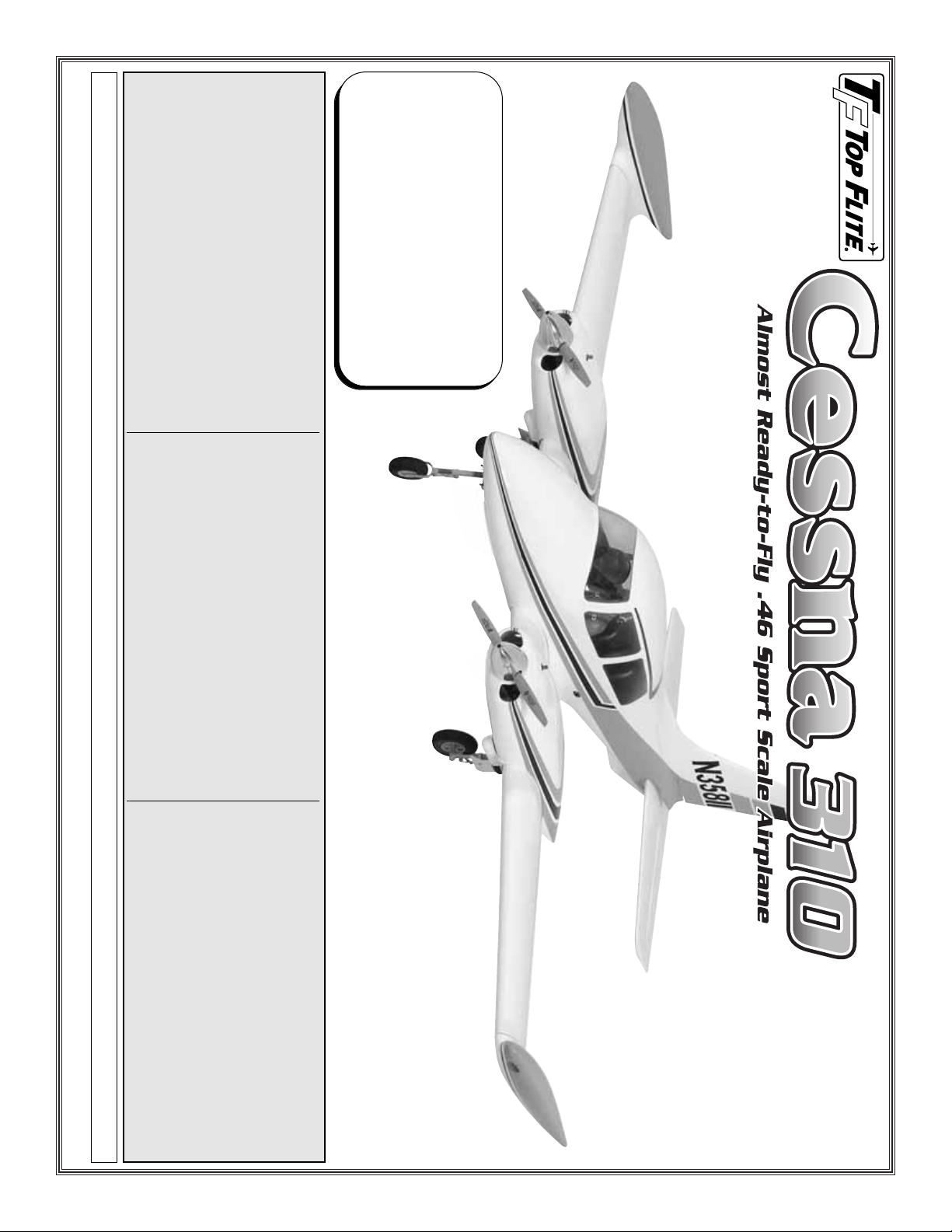
Wingspan: 81 in [2057mm]
Wing Area: 914 sq in [58.9dm
2
]
Weight: 17-20 lb [7710-9070g]
Wing Loading: 43-50 oz/sq ft
[131-153g/dm
2
]
Length: 66 in [1680mm]
Radio: 6-Channel minimum w/8 servos (8- or 9-channel
w/9 servos required for optional retracts)
Engines (2): .46-.51 cu in [7.5-8.5 cc] 2-stroke or
.70-.80 cu in [11.5-13 cc] 4-stroke
Page 2
TABLE OF CONTENTS
INTRODUCTION . . . . . . . . . . . . . . . . . . . . . . . . 2
SAFETY PRECAUTIONS. . . . . . . . . . . . . . . . . . 3
DECISIONS YOU MUST MAKE . . . . . . . . . . . . . 3
Radio Equipment . . . . . . . . . . . . . . . . . . . . 3
Engine Recommendations . . . . . . . . . . . . . 4
Optional Retractable Landing Gear . . . . . . . 4
ADDITIONAL ITEMS REQUIRED. . . . . . . . . . . . 4
Adhesives and Building Supplies. . . . . . . . . 4
Optional Supplies and Tools . . . . . . . . . . . . 4
IMPORTANT BUILDING NOTES . . . . . . . . . . . . 4
ORDERING REPLACEMENT PARTS . . . . . . . . . 5
KIT CONTENTS. . . . . . . . . . . . . . . . . . . . . . . . . 6
PREPARATIONS . . . . . . . . . . . . . . . . . . . . . . . . 7
ASSEMBLE THE FUSELAGE STAND . . . . . . . . 7
ASSEMBLE THE WING . . . . . . . . . . . . . . . . . . . 7
Install the Ailerons and Flaps . . . . . . . . . . . 7
Mount the Plywood Engine Nacelles . . . . . . 9
Install the Flap, Throttle and Aileron
Servos and Pushrods. . . . . . . . . . . . . . . 9
Mount the Wing Tip to the Wing. . . . . . . . . 11
Install the Engine and Fuel Tank . . . . . . . . 12
Install the Fiberglass Nacelles. . . . . . . . . . 13
Install the Spinners . . . . . . . . . . . . . . . . . . 14
Join the Wings . . . . . . . . . . . . . . . . . . . . . 14
ASSEMBLE THE FUSELAGE . . . . . . . . . . . . . 15
Install the Elevator and Rudder . . . . . . . . . 15
Install the Cockpit . . . . . . . . . . . . . . . . . . . 17
Install the Radio, Elevator
and Rudder Servos. . . . . . . . . . . . . . . . 18
INSTALL THE LANDING GEAR . . . . . . . . . . . . 19
Nose Gear . . . . . . . . . . . . . . . . . . . . . . . . 19
Main Gear. . . . . . . . . . . . . . . . . . . . . . . . . 20
RETRACTABLE LANDING GEAR . . . . . . . . . . 22
Nose Gear . . . . . . . . . . . . . . . . . . . . . . . . 22
Main Gear. . . . . . . . . . . . . . . . . . . . . . . . . 23
Install the Retract Hardware . . . . . . . . . . . 25
FINAL ASSEMBLY. . . . . . . . . . . . . . . . . . . . . . 26
Completing the Radio Installation . . . . . . . 26
Connecting the Lighting System . . . . . . . . 26
Apply the Decals. . . . . . . . . . . . . . . . . . . . 27
GET THE MODEL READY TO FLY . . . . . . . . . . 27
Check the Control Directions. . . . . . . . . . . 27
Set the Control Throws . . . . . . . . . . . . . . . 28
Balance the Model (C.G.) . . . . . . . . . . . . . 28
Balance the Model Laterally . . . . . . . . . . . 28
Adjusting the Retractable Landing Gear. . . 29
PREFLIGHT. . . . . . . . . . . . . . . . . . . . . . . . . . . 29
Identify Your Model . . . . . . . . . . . . . . . . . . 29
Charge the Batteries. . . . . . . . . . . . . . . . . 29
Balance Propellers . . . . . . . . . . . . . . . . . . 29
Ground Check. . . . . . . . . . . . . . . . . . . . . . 29
Range Check . . . . . . . . . . . . . . . . . . . . . . 30
ENGINE RUN IN INSTRUCTIONS . . . . . . . . . . 30
ENGINE SAFETY PRECAUTIONS . . . . . . . . . . 30
AMA SAFETY CODE. . . . . . . . . . . . . . . . . . . . 31
IMAA SAFETY CODE . . . . . . . . . . . . . . . . . . . 31
CHECK LIST . . . . . . . . . . . . . . . . . . . . . . . . . . 33
FLYING . . . . . . . . . . . . . . . . . . . . . . . . . . . . . . 33
Takeoff . . . . . . . . . . . . . . . . . . . . . . . . . . . 34
Flight . . . . . . . . . . . . . . . . . . . . . . . . . . . . 34
Landing. . . . . . . . . . . . . . . . . . . . . . . . . . . 34
Engine Out Procedure. . . . . . . . . . . . . . . . 34
INTRODUCTION
Congratulations on the purchase of your Cessna
310! This is one of the finest ARF aircraft we have
ever produced. It is an airplane that is sure to turn
heads at the field and get everyone’s attention as
soon as you are airborne. The molded fiberglass
fuselage and wing tips have faithfully re-created this
classic twin with many fine details and a tremendous
paint finish. Many of the bad tendencies of twin
engine aircraft have been engineered out of this
model so this plane is easily within the capability of
the average intermediate pilot. We are sure this
plane will bring you many hours of flying enjoyment!
For the latest technical updates or manual corrections
to the Cessna 310 visit the Top Flite web site at
www.top-flite.com. Open the “Airplanes” link, then
select the Cessna 310 ARF. If there is new technical
information or changes to this model a “tech notice”
box will appear in the upper left corner of the page.
AMA
In addition to joining a radio control club, we strongly
recommend you join the AMA (Academy of Model
Aeronautics). The AMA is the governing body of
model aviation and membership is required to fly at
AMA clubs. Though joining the AMA provides many
benefits, one of the primary reasons to join is liability
protection. Coverage is not limited to flying at
contests or on the club field. It even applies to flying
at public demonstrations and air shows. Failure to
comply with the Safety Code (excerpts printed in the
back of the manual) may endanger insurance
coverage. Additionally, training programs and
instructors are available at AMA club sites to help
you get started the right way. There are over 2,500
AMA chartered clubs across the country. Contact the
AMA at the address or toll-free phone number below:
Academy of Model
Aeronautics
5151 East Memorial Drive
Muncie, IN 47302-9252
Tele. (800) 435-9262
Fax (765) 741-0057
Or via the Internet at: www.modelaircraft.org
IMPORTANT!!!
Two of the most important things you can do to
preserve the radio controlled aircraft hobby are to
avoid flying near full-scale aircraft and avoid flying
near or over groups of people.
- 2 -
Page 3
IMAA
The Top Flite Cessna 310 is an excellent sport-scale
model and is eligible to fly in IMAA ev ents.The IMAA
(International Miniature Aircraft Association) is an
organization that promotes non-competitive flying of
giant-scale models. If you plan to attend an IMAA
event, obtain a copy of the IMAA Safety Code by
contacting the IMAA at the following address or
telephone number, or b y logging on to their web site .
IMAA
205 S. Hilldale Road
Salina, KS 67401
(913) 823-5569
www.fly-imaa.org/imaa/sanction.html.
SCALE COMPETITION
Though the Top Flite Cessna 310 is an ARF and
may not have the same level of detail as an “all-out”
scratch-built competition model, it is a scale model
nonetheless and is therefore eligible to compete in
the Fun Scale class in AMA competition (we receive
many favorable reports of Top Flite ARFs in scale
competition!). In Fun Scale, the “builder of the
model” rule does not apply.To receive the five points
for scale documentation, the only proof required that
a full size aircraft of this type in this paint/markings
scheme did exist is a single sheet such as a kit box
cover from a plastic model, a photo, or a profile
painting, etc. If the photo is in black and white other
written documentation of color must be provided.
Contact the AMA for a rule book with full details.
If you would like photos of full-size Cessna 310s for
scale documentation, or if you would like to study
the photos to add more scale details, photo packs
are available from:
Bob’s Aircraft Documentation
3114 Y uk on A ve
Costa Mesa, CA 92626
Telephone: (714) 979-8058
Fax:(714) 979-7279
www.bobsairdoc.com
1.Your Cessna 310 should not be considered a toy, but
rather a sophisticated, working model that functions very
much like a full-size airplane. Because of its
performance capabilities, the Cessna 310, if not
assembled and operated correctly, could possibly cause
injury to yourself or spectators and damage to property.
2. You must assemble the model according to the
instructions. Do not alter or modify the model, as
doing so may result in an unsafe or unflyable model.
In a few cases the instructions may diff er slightly from
the photos.In those instances the written instructions
should be considered as correct.
3.You must take time to build straight, trueand strong.
4.You must use an R/C radio system that is in first-
class condition, and correctly sized engines and
components (fuel tank, wheels, etc.) throughout the
building process.
5. You must correctly install all R/C and other
components so that the model operates correctly on
the ground and in the air.
6. You must check the operation of the model before
every flight to insure that all equipment is operating and
that the model has remained structurally sound.Be sure
to check clevises or other connectors often and replace
them if they show any signs of wear or fatigue.
7. If you are not an experienced pilot or have not flown
this type of model before, we recommend that you get
the assistance of an experienced pilot in your R/C club
for your first flights.If you’ re not a member of a club , your
local hobby shop has information about clubs in your
area whose membership includes experienced pilots.
8. WARNING: The cowl, fuselage, nacelles and tail
cone included in this kit are made of fiberglass, the
fibers of which may cause eye, skin and respiratory
tract irritation. Never blow into a part to remove
fiberglass dust, as the dust will blow back into your
eyes. Always wear safety goggles, a particle mask
and rubber gloves when grinding, drilling and sanding
fiberglass parts.Vacuum the parts and the work area
thoroughly after working with fiberglass parts.
Remember: Take your time and follow the
instructions to end up with a well-built model that
is straight and true.
DECISIONS YOU MUST MAKE
This is a partial list of items required to finish the
Cessna 310 that may require planning or decision
making before starting to build. Order numbers are
provided in parentheses.
RADIO EQUIPMENT
Transmitter and Receiver
A minimum of a 6 channel radio is required but
because of the number of servos in this model you
may wish to eliminate the use of “Y” connectors. An
8- or 9- channel radio may be preferable.
Servos
(2) 40 oz-in servos for the throttles
(1) 40 oz-in servo for the retract (optional)
(6) 54 oz-in servos 2-flaps, 2-ailerons,
1-rudder, 1-elevator
We, as the kit manuf acturer , pro vide you with a top
quality, thoroughly tested kit and instructions, but
ultimately the quality and flyability of your finished
model depend on how you build it; therefore, we
cannot in any way guarantee the performance of
your completed model, and no representations
are expressed or implied as to the performance or
safety of your completed model.
PRO TECT YOUR MODEL,
YOURSELF & OTHERS
FOLLO W THESE IMPORT ANT
SAFETY PRECAUTIONS
- 3 -
Page 4

Servo Extensions
(3) Y-har ness (HCAM2751 for Futaba
®
)
(4) 6" [150mm] extension (HCAM2701 for Futaba)
(2) 12" [300mm] extension (HCAM2711 for Futaba)
(4) 24" [610mm] extension (HCAM2721 for Futaba)
Batteries
1000 mAh NiCd battery for the receiver
500 mAh NiCd battery for the lighting system
ENGINE RECOMMENDATIONS
Engine
The recommended engine size for the Cessna 310 is
a .46-.50 two-stroke. This airplane was extensively
flown on the O.S.
®
.46AX two stroke engines and
Bisson muffler. Though your instincts might tell you
that a plane of this size and weight will be
underpowered with these engines, this is not true.
During our test flights we used these engines for
taking off from grass and asphalt with no problems.
The climb out from take off was impressive. Once the
plane was at altitude the plane was flown at 1/2 to 3/4
throttle. As par t of our testing the plane was flown on
a single engine from both the right and left nacelle.
The O.S. .46 was enough power to maintain flying
altitude, fly a figure eight, and a rectangle approach to
the runway. The airplane has the power to fly on one
engine but not enough to climb out from a missed
landing approach.The O.S..46 or .50 SX is the engine
of choice to keep ev erything hidden under the nacelle.
Muffler
The Bisson Pitts Muffler (BISG4046) fits very well in
the nacelle and is the recommended after market
muffler for the Cessna 310.
OPTIONAL RETRACTABLE
LANDING GEAR
Robart Cessna 310 Retracts (ROBQ1623)
Robart Standard Air Kit with variable
rate valve (ROBQ2302)
10' [1meter] Pressure tubing (ROBQ2369)
(2) Air line quick disconnects (ROBQ2395)
ADDITIONAL ITEMS REQUIRED
ADHESIVES & BUILDING SUPPLIES
This is the list of Adhesives and Building Supplies
that are required to finish the Cessna 310.
❏ 3' [900mm] standard silicone fuel
tubing (GPMQ4131)
❏ 1/2 oz. [15g] Thin Pro
™
CA (GPMR6001)
❏ 1 oz. [30g] Medium Pro CA+ (GPMR6008)
❏ Pro 30-minute epoxy (GPMR6047)
❏ Pro 6-minute epoxy (GPMR6045)
❏ Drill bits: 1/16" [1.6mm], 5/64" [2mm], 3/32"
[2.4mm], 7/64" [2.8mm], 1/8" [3.2mm], 11/64"
[4.4mm]
❏ Silver solder w/flux (GPMR8070)
❏ #1 Hobby knife (HCAR0105)
❏ #11 blades (5-pack, HCAR0211)
❏ Medium T-pins (100, HCAR5150)
❏ Masking tape (TOPR8018)
❏ Threadlocker thread locking cement (GPMR6060)
❏ Denatured alcohol (for epoxy clean up)
❏ Hot melt glue and glue gun (available at hobby,
craft and hardware outlets)
OPTIONAL SUPPLIES & TOOLS
Here is a list of optional tools mentioned in the
manual that will help you build the Cessna 310.
❏ 21st Century
®
sealing iron (COVR2700)
❏ 21st Century iron cover (COVR2702)
❏ 4 oz. [113g] aerosol CA activator (GPMR634)
❏ CA applicator tips (HCAR3780)
❏ Epoxy brushes (6, GPMR8060)
❏ Mixing sticks (50, GPMR8055)
❏ Mixing cups (GPMR8056)
❏ Hobbico Duster
™
compressed air (HCAR5500)
❏ Rotary tool such as Dremel
®
❏ Rotary tool reinforced cut-off wheel (GPMR8020)
❏ Servo horn dr ill (HCAR0698)
❏ Dead Center
™
Engine Mount Hole
Locator (GPMR8130)
❏ AccuThrow
™
Deflection Gauge (GPMR2405)
❏ CG Machine
™
(GPMR2400)
❏ Precision Magnetic Prop Balancer (TOPQ5700)
IMPORTANT BUILDING NOTES
• There are two types of screws used in this kit:
Sheet metal screws are designated by a number
and a length. For example #6 x 3/4" [19mm]
This is a number six screw that is
3/4" [19mm] long.
Machine screws are designated by a number, threads
per inch, and a length.For example 4-40 x 3/4" [19mm]
This is a number four screw that
is 3/4" [19mm] long with forty
threads per inch.
Socket head cap screws are designated by a
number, threads per inch and a length.For example
4-40 x 3/4" [19mm]
This is a number four screw that
is 3/4" [19mm] long with forty
threads per inch
.
• When you see the term test fit in the instructions, it
means that you should first position the part on the
assembly without using any glue, and then slightly
modify or custom fit the part as necessar y for the
best fit.
•Whenever the term glue is written you should rely upon
your experience to decide what type of glue to use.
When a specific type of adhesive works best for that
step, the instructions will make a recommendation.
• Whenever just epoxy is specified you may use
either 30-minute (or 45-minute) epoxy or 6-minute
epoxy. When 30-minute epoxy is specified it is
highly recommended that you use only 30-minute
(or 45-minute) epoxy, because you will need the
working time and/or the additional strength.
• Photos and sketches are placed bef ore the step they
refer to .Frequently you can study photos in follo wing
steps to get another view of the same parts.
- 4 -
Page 5

• The Cessna 310 is factory-covered with Top Flite
MonoKote
®
film. Should repairs ever be required,
MonoKote can be patched with additional MonoKote
purchased separately. MonoKote is packaged in six-
foot rolls, but some hob by shops also sell it by the f oot.
If only a small piece of MonoKote is needed for a
minor patch, perhaps a fellow modeler would giv e y ou
some. MonoKote is applied with a model airplane
covering iron, but in an emergency a regular iron could
be used. A roll of MonoKote includes full instructions
for application. Following are the colors used on this
model and order numbers for six foot rolls.
White - TOPQ0204
Sky Blue - TOPQ0206
Insignia Blue - TOPQ0207
METRIC CONVERSIONS
To convert inches to millimeters, multiply inches by 25.4
.4mm = 1/64"
.8mm = 1/32"
1.6mm = 1/16"
2.4mm = 3/32"
3.2mm = 1/8"
4mm = 5/32"
4.8mm = 3/16"
6.4mm = 1/4"
9.5mm = 3/8"
12.7mm = 1/2"
15.9mm = 5/8"
19mm = 3/4"
25.4mm = 1"
50.8mm = 2"
76.2mm = 3"
152.4mm = 6"
304.8mm = 12"
381mm = 15"
457.2mm = 18"
533.4mm = 21"
609.6mm = 24"
762mm = 30"
914.4mm = 36"
ORDERING REPLACEMENT PARTS
Replacement parts for the Top Flite Cessna 310 are
available using the order numbers in the
Replacement Parts List that follows. The fastest,
most economical service can be provided by your
hobby dealer or mail-order company.
To locate a hobby dealer, visit the Hobbico web site
at www.hobbico.com. Choose “Where to Buy” at the
bottom of the menu on the left side of the page.
Follow the instructions provided on the page to
locate a U.S., Canadian or International dealer.
Parts may also be ordered directly from Hobby
Services by calling (217) 398-0007, or via facsimile
at (217) 398-7721, but full retail prices and shipping
and handling charges will apply. Illinois and Nevada
residents will also be charged sales tax. If ordering
via fax, include a Visa
®
or MasterCard
®
number and
expiration date for payment.
Mail parts orders and payments by personal check to:
Hobby Services
3002 N Apollo Drive, Suite 1
Champaign IL 61822
Be certain to specify the order number exactly as
listed in the Replacement Parts List. Payment by
credit card or personal check only; no C.O.D.
If additional assistance is required for any reason
contact Product Support at:
(217) 398-8970
productsupport@greatplanes.com
REPLACEMENT PARTS LIST
Description How to purchase
Missing pieces Contact Product Support
Instruction manual Contact Product Support
Full-size plans Not available
Order # Description
TOPA1660 Wing Set
TOPA1661 Fuselage Set
TOPA1662 Wing Tip Set
TOPA1663 Tail Set
TOPA1664 Left Engine Pod
TOPA1665 Right Engine Pod
TOPA1666 Landing Gear
TOPA1667 Decal Set
TOPA1668 Wing Tubes (2)
TOPA1669 Tail Tubes (2)
TOPA1670 Windshield/Windows
TOPA1671 Gear Doors
TOPA1672 Aluminum Spinner
TOPA1673 Tail Cone
TOPA1674 Rudder
- 5 -
Page 6
- 6 -
PARTS NOT PHOTOGRAPHED
(2) 2-56 Metal Clevis
(1) 4-40 Threaded Metal Clevis
(2) 4-40 Solder Clevis
(4) Brass Screw Lock Connector
(2) 4-40 Nut
(8) 6-32 Blind Nut
(2) 8-32 Blind Nut
(2) 2-56 Nut
(3) .080 Nut
(7) 1/4-20 Blind Nut
(2) Large Nylon Control Horn
(6) 1/4-20 Bolts
(4) 2-56 Nylon Clevis
(2) Large Black Control Horn
(1) 2-56 Nylon Ball Link Socket
(4) Nylon Retainer
(2) CA Hinge Strip
(5) Faslink
(2) 36" Gray outer Pushrod Tube
(9) Silicone Clevis Keeper
(8) #4 x 1/2" [13mm] Sheet
Metal Screw
(2) 4-40 x 1/4" [6mm] SHCS
(32) #2 x 3/8" [10mm] SMS
(16) #6 x 1/2" [13mm] SMS
(4) 8-32 x 1" [25mm] Slotted MS
16 6-32 x 3/4" [19mm] SHCS
(3) .080 Ball
(8) #2 x 3/8" [10mm] Wood Screw
(2) 8-32 x 1" [25mm] SHCS
(4) 4-40 x 1/8" [3mm] SHS
(8) #2 x 1/2" [13mm] SMS
(2) .074 x12" Wire [305mm]
(5) .074 x 6" [152mm] Wire
(2) 4-40 x 36" [914mm] Threaded Rod
(32) #6 Flat Washer
(2) #4 Flat Washer
(20) #2 Flat Washer
(2) #8 Lock Washer
(14) #8 Flat Washer
(28) #6 Lock Washer
(4) Crimp Connector
(1) 1/4-20 Thumb Screw
(4) Flat Nylon Strap
(4) Humped Landing Gear Strap
(3) 4x200mm Nylon Tie Strap
(1) .5 x 1000mm Cable
(2) 8x40mm Nylon Dowel with Pin
(4) 8x30mm Nylon Dowel
(2) 2-56 Brass Connector
(8) Pinned Hinge
(2) Aluminum Door Mount Brackets
(8) 2 x 10mm Screws
(8) 2mm Nuts
(6) Wheel Collars and Set Screws
(3) Fiberglass Landing Gear Doors
(1) 4-40 x 12" [305mm] Fully
Threaded Rod
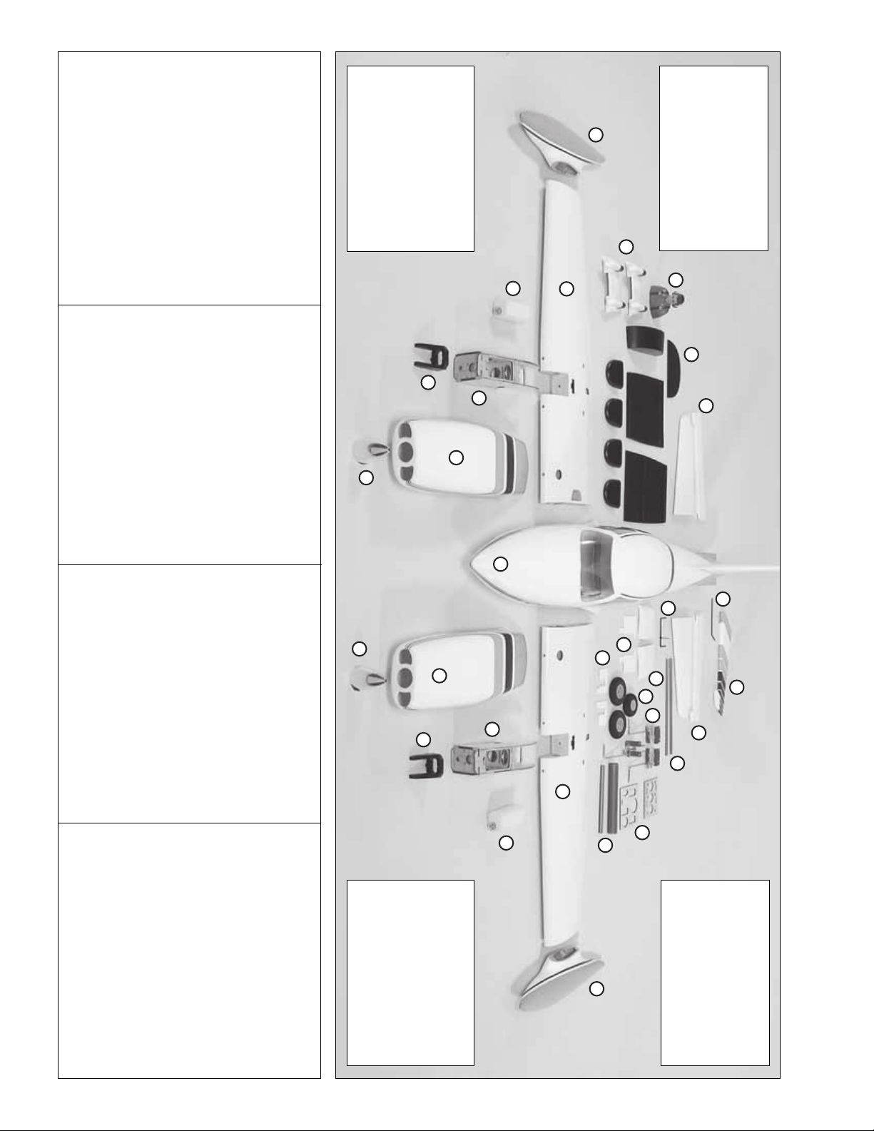
KIT CONTENTS
1. Fuselage
2. Nacelles (L&R)
3. Spinners
4. Engine Mounts
5. Fuel Tanks
6. Wood Nacelle (Left)
14. Pilot
15. Wing Fairing (L&R)
16. Gear Door (L&R)
17. Landing Gear Covers
18. Wheels
19. Landing Gear
7. Wood Nacelle (Right)
8. Wing Half (Left)
9. Wing Half (Right)
10. Wing Tip (Right)
11. Wing Tip (Left)
12. Lower Nacelle Covers
13. Cockpit Kit
20. Ser vo and Battery Tray
21. Wing Joiner Tubes
22. Stab T ubes
23. Elevator Joiner Wire
24. Stabilizer (L&R)
25. Rudder Control Wire
26. Rudder
10
12
4
3
3
4
5
7
2
9
14
13
24
1
23
16
17
2
6
15
18
19
22
25
26
24
8
5
11
20
21
Page 7
- 7 -
PREPARATIONS
❏ 1. If you have not done so already, remove the
major parts of the kit from the box and inspect for
damage. If any parts are damaged or missing,
contact Product Support at the address or telephone
number listed in the “Ordering Replacement Parts”
section on page 5.
❏ 2.Remove the tape and separate the ailerons and
flaps from the wing and the elevators from the stab.
Use a covering iron with a covering soc k on high heat
to tighten the covering if necessary. Apply pressure
over sheeted areas to thoroughly bond the covering
to the wood.
ASSEMBLE THE FUSELAGE STAND
Your kit includes a stand that can be used during the
assembly process and as a useful tool for transporting
the airplane to the field as well as assembly of the
airplane at the field.
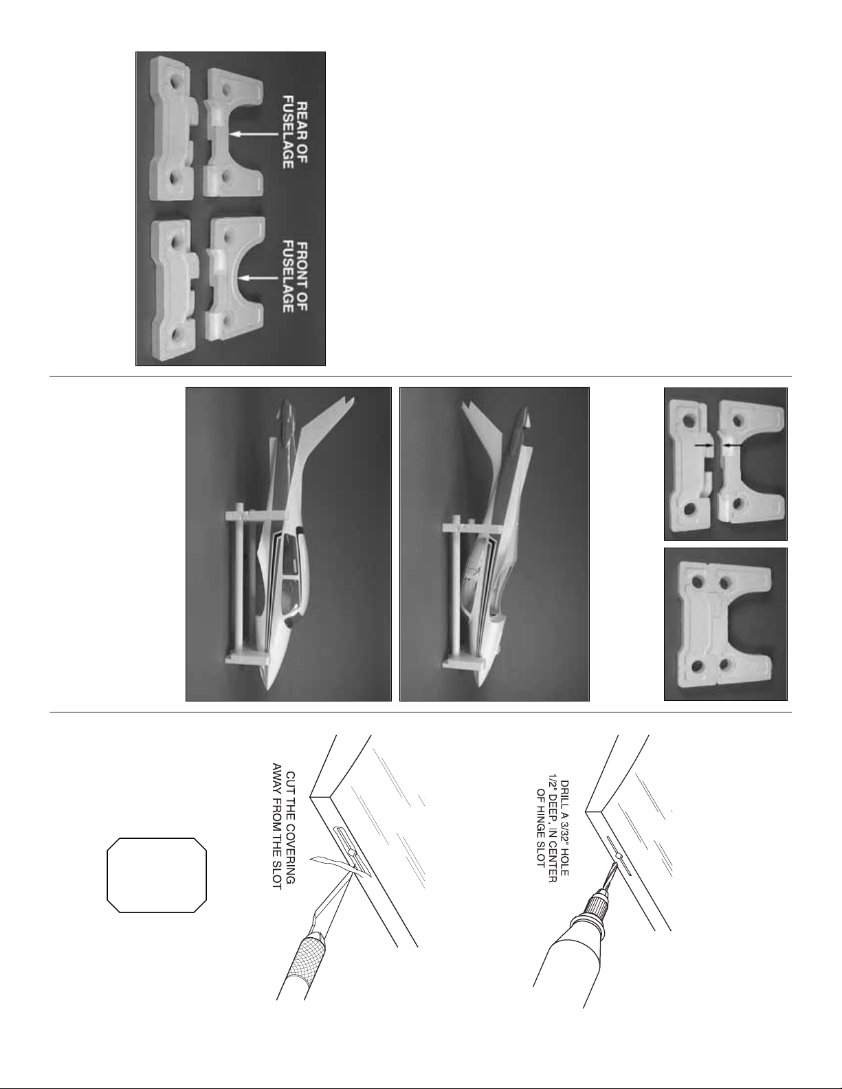
❏ 1. The stand consists of four foam cradle
components and two PVC tubes. There are two
different cutouts in the cradle.The curved section fits
the front of the fuselage while the one that has the
flat cut fits the rear half of the fuselage.
❏ 2. The top and bottom stand components will fit
snugly together. Fit the bottom with the top cradle
(the one with the flat cut) as shown.
❏ 3. When placed into the cradle upside down the
fuselage is elevated so the tail and the cabin top are off
of your work bench. You can also place the fuselage
upright in the cradle.If you install the fixed landing gear
and wish to transport the fuselage or work on it on your
workbench, you will want to place the other bottom
cradle component onto the front cradle.This will allow
enough clearance for the nose gear.
ASSEMBLE THE WING
Install the Ailerons and Flaps
Assemble the right wing first so your
work matches the photos.
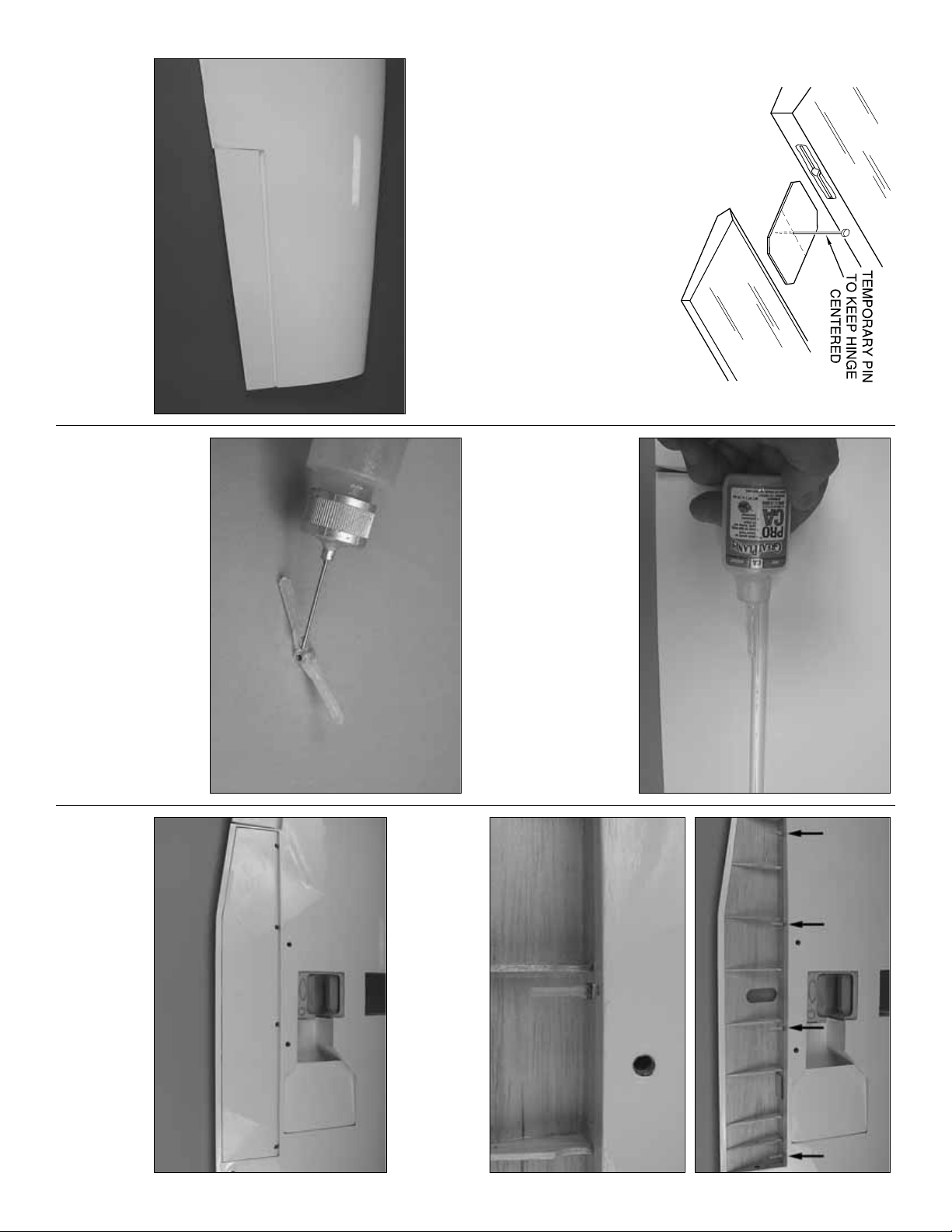
❏❏1. Drill a 3/32" [2.4mm] hole, 1/2" deep in the
center of each hinge slot to allow the CA to “wick”in.
Follow-up with a #11 blade to clean out the slots.
Hint: If you ha v e one , use a high-speed rotary tool to
drill the holes.
❏❏2. Use a sharp #11 blade to cut a strip of
covering from the hinge slots in the wing and aileron.
❏❏3.Cut three 1" x 1" [25mm x25mm] hingesfrom
the CA hing e strip. Snip off the corners so they go
in easier.
Page 8
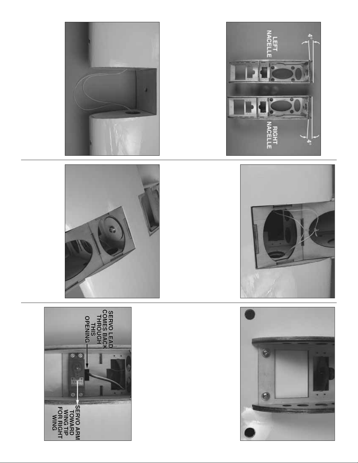
❏❏4. Test fit the ailerons to the wing with the
hinges.If the hinges don’t remain centered, stick a pin
through the middle of the hinge to hold it in position.
❏❏5.Remove any pins you may have inserted into
the hinges. Adjust the aileron so there is a small gap
between the LE of the aileron and the wing.The gap
should be small, just enough to see light through or
to slip a piece of paper through.
❏❏6. Apply six drops of thin CA to the top and
bottom of each hinge. Do not use CA accelerator.
After the CA has fully hardened, test the hinges by
pulling on the aileron.
❏❏7. If you have not removed the flap from the
wing, do so. Locate four nylon pinned hinges. Apply
a drop of oil or work Vaseline into the hinge. This will
prevent glue from getting into the hinge in the next
step. Be careful not to get oil on the portion of the
hinge that slides into the wing and flap.If this should
happen be sure to clean the hinge with alcohol
before applying the glue.
❏❏8. Apply epoxy to one end of each hinge and
into each of the four holes in the wing trailing edge in
the flap compartment. Insert the hinge into the hole,
positioning the hinge as shown.
❏❏9. Apply epoxy to the opposite end of the hinge
and the hinge holes in the flap.Insert the flap onto the
hinges. Set the wing aside until the glue has cured.
❏ 10. Repeat steps 1- 9 for the left wing panel.
- 8 -
Page 9
Mount the Plywood Engine Nacelles
❏
1. Remove the top plate and fuel tank from the
plywood engine nacelle. Set the two plywood
engine nacelles on your workbench as shown in the
photograph. Looking at the top of the nacelle you
must note the difference in the angle of the firewall
of each nacelle. Each nacelle has 4° of outward
thrust built into it. Write the word “left” and “right” on
each nacelle so you can easily identify each one.
❏❏2. The wing has strings running through it for
pulling servo leads through the wing.The string is taped
at the root rib, the wing tip and inside the aileron servo
compartment. Remove the tape and pull the excess
string into the front of the wing where the nacelle will be
mounted. Re-tape the end of the string to the rib.
❏❏3.Cut the strings.Begin sliding the right nacelle
in place and at the same time feed the string through
the holes in each side of the nacelle. Re-tie the
strings.Apply a drop of thin CA to the knot to prevent
it from coming apart.
❏❏4. Slide the nacelle completely into the wing.
Attach the nacelle to the wing with an 8-32 x 1"
[25mm] socket head cap screw, a #8 lock washer
and a #8 flat washer. Apply a couple of drops of
thread locker onto the bolt before tightening the bolt
to the wing and nacelle.
❏❏5. Drill 3/32" [2.4mm] holes through each of the
two pilot holes located at the back of the nacelle.Drill
through the nacelle and into the hardwood block
located in the wing. Inser t and remove a #6 x 1/2"
[13mm] screw into each of the holes.Apply a couple
drops of thin CA into the holes to harden the threads.
Once the glue has cured install the #6 screws and #6
flat washers into each of the holes.
❏ 6. Repeat steps 1- 5 for the left wing panel.
Install Flap,Throttle and Aileron
Servos and Pushrods
❏❏1.Install the flap servo into the rear servo opening.
Insert and remove a servo mounting screw into each of
the pre-drilled holes. Apply a couple drops of thin CA
- 9 -
Page 10
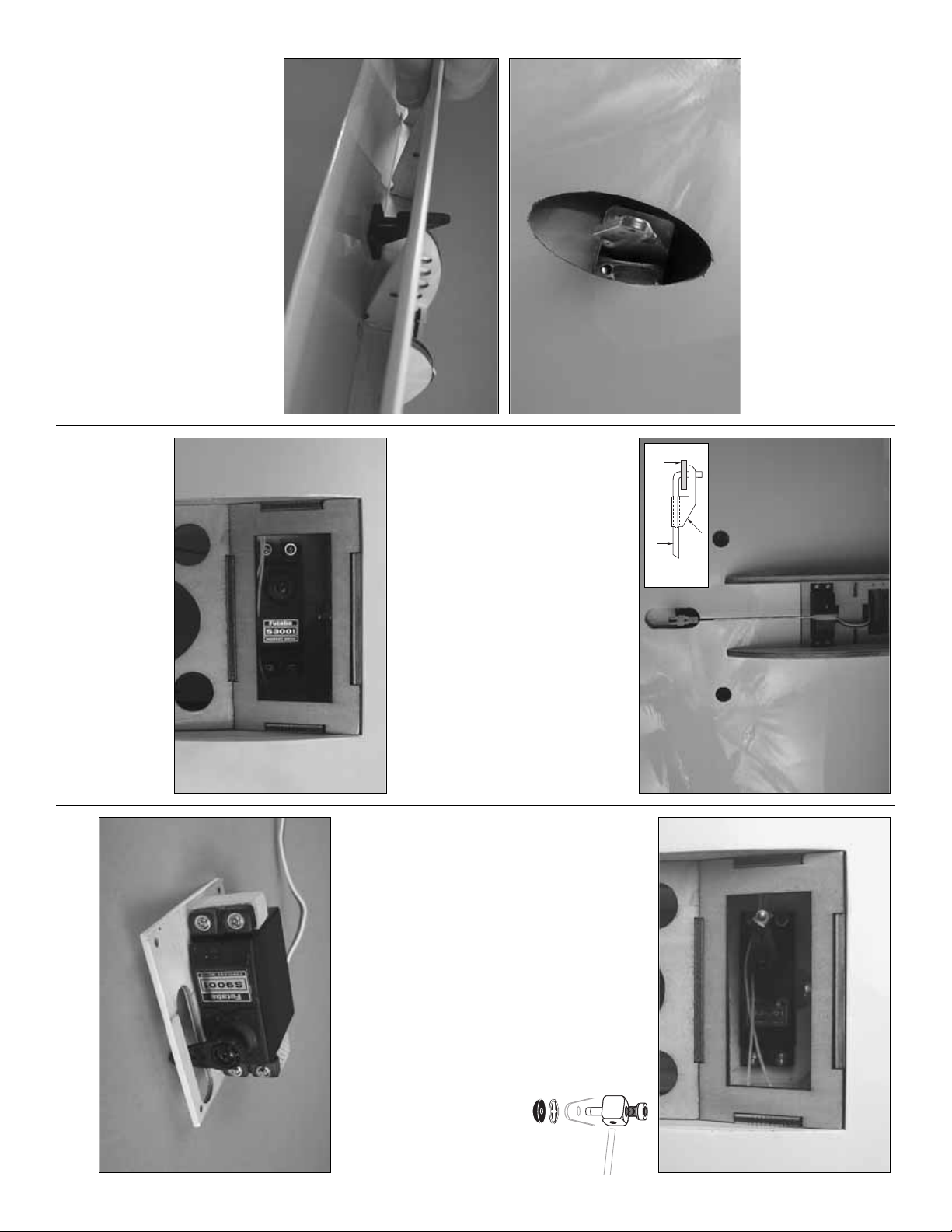
into the holes to harden the threads.Once the glue has
cured re-install the servo mounting screws.Be sure the
servo lead comes up through the slot alongside of the
servo. When installing the flap ser vo in the right wing
panel, the servo arm should be pointed towards the
wing tip.When installing the servo in the left wing, the
arm should be pointed towards the wing center.
❏❏2. Center a black control horn in the opening
above the flap , positioning it as shown (the control horn
should be backwards from what would be considered
the normal direction of a control horn.) Drill a 1/16"
[1.6mm] hole through each of the mounting holes in the
control horn and into the plywood plate in the flap.Drill
only through the plywood plate. DO NOT drill through
the flap. Inser t and remove a #2 x 3/8" [10mm] screw
into each of the holes.Apply a couple drops of thin CA
into the holes to harden the threads.Once the glue has
cured attach the horn to the flap with four
#2 x 3/8" [10mm] screws.
❏❏3.Screw a nylon clevis onto a .074 x 6" [152mm]
threaded wire 20 turns. Slide a nylon clevis retainer
onto the clevis. Install the clevis into the outermost
hole of the control horn. Then slide the silicone
retainer over the clevis. Drill a 5/64" [2mm] hole in the
outer hole of the servo arm. Position the servo arm as
shown and be sure the flap is fully closed.With a fine
tip marker, mark the wire where it aligns with the outer
hole of the servo arm. Make a 90 degree bend on the
mark. Cut the wire so the wire is 3/8" [10mm] in length
after the bend. Insert the wire into the servo arm and
lock it in place with a nylon Faslink.
❏❏4. Install the throttle ser vo into the servo opening.
(Note that the servo is mounted on the bottom of the
nacelle).Insert and remove a servo mounting screw into
each of the pre-drilled holes.Apply a couple drops of thin
CA into the holes to harden the threads. Once the glue
has cured, re-install the servo mounting screws.
❏❏5. Install a brass screw lock
connector, nylon retainer ring and a
4-40 x 1/4" [6mm] socket head cap
screw onto the servo arm. Then
center the servo and install the arm
onto the servo.
❏❏6. Install a 6" [152mm] servo extension onto the
throttle and flap servo leads. Secure the extension to
the lead with tape, a piece of shrink tube or some
other method to keep them from coming unplugged.
❏❏7. Install a 24" [610mm] servo extension onto
the aileron servo lead. Secure the extension to the
lead with tape, a piece of shrink tube or some other
method to keep them from coming unplugged.
❏❏8. Install the aileron servo between the wooden
rails under the aileron servo cover using the
- 10 -
SERVO
HORN
PUSHROD WIRE
2-56 (.074")
FASLINK
Page 11
- 11 -
hardware that came with the servo. Drill a 1/16"
[1.6mm] hole through each of the servo mounting
holes and into the servo mounting rails. Inser t and
remove a servo mounting screw into each of the
holes. Apply a couple drops of thin CA into the holes
to harden the threads. Once the glue has cured,
re-install the servo mounting screws.
❏❏9. Center the servo.Then, install a large ser vo
horn to the servo.
❏❏10. Tie the string from the ser vo compartment
to the servo lead. Pull the lead through the wing
exiting at the nacelle.Leave the string attached to the
lead for now.
❏❏11. Install the aileron ser vo cover to the wing
with four #2x 3/8"[10mm] wood screws.
❏❏12.Look closely under the covering of the aileron
and you will see a plywood mounting plate for the
control horn. Place a nylon clevis on the plate in line
with the servo arm. Mark the location of the mounting
holes onto the aileron. Drill a 1/16" [1.6mm] hole on
the marks, drilling through the plywood plate
but not
through the top of the aileron. Insert and remove a #2
x3/8" [10mm] screw into each of the holes. Apply a
couple drops of thin CA into the holes to harden the
threads. Once the glue has cured, attach the horn to
the aileron with two #2 x 3/8" [10mm] screws.
❏❏13.Screw a nylon clevis onto a .074 x 6" [152mm]
threaded wire 20 turns.Slide a nylon clevis retainer onto
the clevis.Install the clevis into the second hole from the
end of the control horn. Then slide the silicone retainer
over the cle vis.Drill a 5/64" [2mm] hole in the outer hole
of the servo arm. Center the servo and position the
servo arm as shown. Then, center the aileron. With a
fine tip marker, mark the wire where it aligns with the
outer hole of the servo arm. Make a 90 degree bend on
the mark. Cut the wire so the wire is 3/8" [10mm] in
length after the bend.Insert the wire into the servo arm
and lock it in place with a nylon Faslink.
❏ 14. Repeat steps 1- 13 for the left wing panel.
Mount the Wing Tip to the Wing
❏❏1. Glue two 1/4" x1/4" x 3/4" [6mm x 6mm x
19mm] balsa triangle blocks onto each side of the
slot in the wing.
❏❏2.Examine both wing tips to determine which is
the left and the right. When installed on the wing the
tip should curve upward towards the top of the wing.
❏❏3. Pull the wires for the wing tip lights from
inside of the wing tip. Tie the end of the wire to the
string located on the end of the wing. Pull the wire
through the wing exiting at the nacelle. Note: at this
point all of the servo leads and the wire for the light
should be at the nacelle.
Page 12

❏❏4. Test fit the wing tip to the wing. Once you’re
satisfied everything fits, apply epoxy into the pocket
in the end of the wing, the plywood tongue on the
wing tip, the tip of the wing and the root rib of the
wing tip. Tape the wing tip to the wing. Set it aside
until the glues has cured.
❏❏5. At this point the servo leads as well as the
lead for the wing tip lights should be located at the
nacelle. Untie both of the strings from the servo
leads.If you will be installing retractable landing gear,
tape one of the strings to the wing. This will be used
later to pull the air lines through the wing. Tie all of
the leads to the other string. If you will be installing
fixed gear tie two leads to each string.This will make
it easier to pull the leads through the wing. Pull all of
the servo leads and the wing tip light wire through
the wing, exiting through the hole in the top of the
wing.Untie the leads and then tape all of the leads to
the top of the wing, preventing the leads from falling
back into the wing. If you are installing retracts be
sure to leave the string taped to the root rib.
❏ 6. Repeat steps 1- 5 for the left wing panel.
Install Engine and Fuel Tank
❏❏1. Cut the tabs from the engine mount. Install
the engine mount to the firewall with four 6-32x 3/4"
[25mm] socket head cap screws , #6 flat washers and
#6 lock washers.
❏❏2. Position the engine on the engine mount so
the distance from the firewall to the thrust washer
measures 4-5-8" [118mm]. Mark the location of the
mounting holes onto the engine mount. Drill and tap
the engine mount with a 6-32 tap for each of the four
bolts.Mount the engine to the mount with four 6-32 x
3/4" [25mm] socket head cap screws , #6 flat washers
and #6 lock washers.
❏❏3. Assemble the fuel tank as shown in the
sketch.When tightening the center screw be sure not
to over tighten it.You just want it snug enough to pull
the rubber stopper tight against the tank.
❏❏4.Install the tank into the fuselage with the neck
of the tank through the firewall.
- 12 -
SILICONE
FUEL LINE
FUEL TANK
FUEL CLUNK
FUEL
PIPE
FIREWALL
TO NEEDLE
VALVE
PRESSURE
TAP TO
MUFFLER
Page 13

❏❏5. From one of the 1/4" x 1/4" x 12" [6mm x 6mm
x 305mm] balsa sticks, cut two sticks to a length of 1"
[25mm]. Insert them into the square openings on each
side of the bottom of the nacelle. Make sure they
extend into the nacelle far enough to support the fuel
tank.Then, glue them in place.
❏❏6. Install silicone fuel tubing onto the aluminum
tubes from the fuel tank. The line with the fuel clunk
will feed to the fuel inlet at the needle valve and the
other will attach to the pressure tap on the muffler.If
you choose to use some kind of an external fuel
valve, follow the instructions with your particular
brand of fuel valve.You can also install a third line to
the tank and use it for filling the tank.The method you
use is your choice but make your decision before
moving onto the installation of the fuel tank.
❏❏7 Install a brass screw lock connector, nylon
retainer ring and a 4-40 x 1/4" [6mm] socket head cap
screw onto the throttle arm on the engine. Cut the
threaded portion off of a 2-56 x 12" [305mm] pushrod
wire. Slide the wire through the screw lock connector
on the throttle arm, pushing it back towards the throttle
servo.Bend the wire as needed to clear the top of the
fuel tank and reach the screw lock connector. Tighten
the set screws against the wire pushrod.
❏❏8. Epoxy the top of the nacelle in place.
A note about the muffler: A wide variety of mufflers
are available. On our O.S .46 we used the Bison
muffler (BISG4046) and cut the pipes to a length of
3/8" [10mm]. This allowed the cowl to slip over the
engine and muffler yet still allows the e xhaust to clear
the inside of the nacelle. Cut the pipes as shown.
Leave the muffler off the engine for now. This will
make the installation of the fiberglass nacelle easier.
❏ 9. Repeat steps 1- 8 for the left wing panel.
Install Fiberglass Nacelle
❏❏1. Glue two of the 1/4 x 1-1/8" [6mm x 30mm]
nylon dowels into the leading edge of the wing on
each side of the nacelle with epoxy. The dowels
should extend from the leading edge of the wing
approximately1/2" [13mm].
❏❏2. Place the two nacelles side by side. Each
have outboard thrust angles built into the front of the
nacelle. Identify the right and left and mar k this on
the inside of the nacelle.
- 13 -
Page 14

❏❏3. Slide the nacelle over the engine and onto
the locating dowels on the leading edge of the wing.
Note: You may have to remove the needle valve
and/or the needle valve spring to get the nacelle
completely over the engine.Secure the nacelle to the
wing with two 1/4-20 x 2" [51mm] nylon bolts on the
bottom of the wing.
❏❏4. Place the nacelle belly pan onto the bottom
of the wing, placing it tight against the nacelle.Drill a
1/16" [1.6mm] hole at the location shown, making
sure to drill only through the wood under the pan.
Install and then remove a #2 x 1" [25mm] sheet metal
screw into each of the holes. Apply a few drops of
thin CA into the holes. After the glue has cured,
screw the belly pan in place.
❏❏5. Make the necessary cut-outs for the needle
valve, muffler, glow driver, etc.
❏❏6. It is very important that you provide an air
exhaust to allow the engine to be cooled properly.
With the engine completely cowled, you must provide
approximately 5 sq. in. [.35 dm
2
] of exhaust area on
the bottom of the wing nacelle.
❏❏7. Epoxy one of the two 5/16 x 1-1/2" [8mm x
40mm] nylon dowels with the steel pin in its center
into the hole in the leading edge of the wing. Insert
the pin fully into the hole in the leading edge.
❏ 8. Repeat steps 1-7 for the other wing.
Install the Spinners
❏❏Install the spinners to the engine with the
hardware included with the spinners.When mounting
the propellers you will need to use the nut that came
with the spinners rather than the nut that came with
the engine.
Join the Wings
❏ 1. Slide the two aluminum tubes into one of the
wing halves. Slide the other wing onto the tubes.
Push the wings tightly together.
- 14 -
Page 15

❏ 2. Inser t the 1/4-20 thumbscrew into the opening
in the right wing panel.Tighten the screw, pulling the
wings together.
❏ 3. Place the fuselage upside down into the foam
stand. Install the wing onto the fuselage, securing it
with two 1/4-20 nylon wing bolts.
❏ 4. Locate the two fiberglass wing fairings. Place
them on each wing. Trace the outline of the fairing
onto the wing.Using a sharp modeling knife, carefully
cut the covering from the wing. Be careful to only cut
through the covering, not the surface of the wing.
❏ 5. Glue the fairings to the wing. After the glue has
cured, remove the wing from the fuselage and
separate the two halves of the wing.
ASSEMBLE THE FUSELAGE
Install the Elevator and Rudder
❏ 1. Locate the rudder control wire and the r udder
control horn.Note that the wire has a flat spot pre-cut
in the end of the wire.
❏ 2. Slip the rudder control wire into the hole in the
top of the fuselage.
❏ 3. Put a 4-40 nut onto a 4-40 x 36" [914mm] wire
pushrod.Screw the wire pushrod into the nylon swiv el
connector approximately 20 turns. Lock the nut
against the connector.From the back of the fuselage,
slide the pushrod wire into the center plastic guide
tube that is pre-installed in the fuselage. Slide the
rudder control wire through the nylon bearing. Place
the rudder control horn onto the rudder control wire.
When installing it over the wire be sure the control
arm is on the left side of the fuselage.Remove the set
screw from the control horn and apply a couple of
drops of thread locker to the threads. Re-insert the
screw into the control horn, tightening the set screw
against the flat spot on the rudder control wire.
- 15 -
Page 16

- 16 -
❏ 4. Insert the elev ator joiner wire into the holes in the
sides of the fuselage following the sequence shown.
❏ 5. Slide the aluminum stabilizer tubes into the
back of the fuselage.Test fit the two stabilizer halves
onto the tubes. Be sure the stabilizer fits snug to the
sides of the fuselage.Once you are satisfied with the
fit, remove the stabilizers from the tubes.
❏ 6. WIth 200-grit sandpaper, roughen the fuselage
where the stabilizers make contact with the fuselage.
Glue the stabilizer halves to the fuselage with epoxy.
Tape the stabilizers in place until the glue has hardened.
❏ 7. Cut six 1" x 1" [25mm x 25mm] hinges from the
CA hinge strip. Snip off the corners so they go in
easier. Install three hinges into each of the elevator
halves and trial fit the elevators to the stab. Once
satisfied with the fit, remove the elevators from the
stab. Apply a small amount of epoxy to the elevator
joiner wires.With the hinges installed in the elevator,
slide the elevators onto the joiner wire and into the
hinge slots, securing the hinges to the stabilizer with
thin CA the same way you did the ailerons.
❏ 8. Cut three 1" x 1" [25mm x 25mm] hinges from the
CA hinge strip.Snip off the corners so they go in easier.
❏ 9. Insert the hinges into the hinge slots of the
vertical fin. Keep the hinges centered using a pin.
Page 17

❏ 10. Trial fit the rudder onto the hinges and the
vertical fin. Once satisfied with the fit, remove the
rudder. Apply a small amount of epoxy to the rudder
wire.With the hinges installed in the rudder, slide the
rudder in position.Secure the hinges with thin CA the
same way as was done for the elevator.
Install the Cockpit
The cockpit needs to be installed now, before the
installation of the servos.Do not skip this step thinking
you will install the cockpit after the rest of the plane is
complete. The cockpit can be installed permanently
but if you’re like most modelers you may lik e the ability
to remove it at a future date.The following instructions
will allow the cockpit to be removed should there ever
be a need to do so.
❏ 1. Locate the components of the cockpit interior.
Cut the instrument panel decal from the decal sheet
and install it to the instrument panel bulkhead. Glue
the four seat backs, the instrument panel and the
back of the cockpit in place.Glue pilot in place.
❏ 2. Located inside of the fuselage, on both sides of
the fuselage, are wood tabs.These are to be used to
help locate the cockpit floor. Position the cockpit just
above these blocks.
❏ 3. Install the cockpit into position with a hot melt
glue gun.This glue sets quickly yet is easily removab le
should you ever need to remove the cockpit.If you do
not have a hot melt glue gun you can also use silicone
though this will take longer to set up.
- 17 -
Page 18

Install Radio, Elevator & Rudder Servos
❏ 1. Plug the wire from the landing light located in the
nose of the fuselage into the wiring harness inside
the fuselage.
❏ 2.If you plan to install retractable landing gear you
need to install the air tank now .Glue the tank into the
opening on the right side of the fuselage. Hot melt
glue or epoxy mixed with microballoons works well.
❏ 3. Glue the two 3/16" x 3/8" x 9" [4mm x 10mm x
230mm] hardwood servo tray mounting rails inside
the fuselage.The mounting rails must be located on
the top of the balsa rails already glued to the
fuselage sides and spaced as shown in the photo.
❏ 4. Test fit the radio and servo tray to the rails you
glued into the fuselage. Note that the trays fit between
the balsa longerons on the fuselage sides. Once you
are satisfied with the fit of the trays, drill a 1/16" [1.6mm]
hole through the servo and radio trays, drilling through
the servo mounting rails. Secure both trays to the rails
with eight #2 x 3/8" [10mm] sheet metal screws and #2
flat washers.
❏ 5. Install a 4-40 nut, 4-40 threaded clevis and
silicone clevis keeper onto the threaded end of a 4-40
x 36" [914mm] wire pushrod. From the back of the
fuselage slide the elevator wire into the pre-installed
plastic pushrod tube for the elevator. Attach the clevis
to the elevator control horn.
❏ 6. Using the hardware provided with the servos,
install the elevator servo into the servo tra y as sho wn.
Center the elevator servo. Align the elevator pushrod
wire with the servo arm.To get a good alignment with
the servo arm, adjust the pushrod wire by making
slight bends as needed to the wire. Install a 4-40
solder clevis onto the servo arm. Center the elevator
and then mark the pushrod wire and cut it to length.
Remove the clevis from the ser vo arm.
❏ 7. Solder the clevis to the wire. Slide a clevis
keeper over the clevis. Then, attach the clevis to the
servo arm.
❏ 8. Install the rudder servo following the same
procedure used with the elevator servo. For the
rudder use a double servo arm and install the clevis
one hole in from the outermost hole as shown.
- 18 -
Page 19

❏ 9. Place 1/4" [6mm] foam under the receiver and
battery .Hold them to the tray with the plastic tie wraps.
Route the receiver antenna through the antenna tube,
securing the antenna at the back of the fuselage.
Note:If you are going to be utilizing the lighting system
on this airplane, you should hold off on installing the
receiver battery until you are instructed to install the
battery for the lights.The same plastic tie wraps used
for the receiver battery will be used to hold the battery
for the lighting system in place.
❏ 10. Position the tail cover in place on the bottom of
the fuselage.Drill a 1/16" [1.6mm] hole in each corner
of the cover. Remove the cover and drill a 3/32"
[2.4mm] hole through each of the holes you drilled in
the cover. Secure the cover to the fuselage with four
#2 x 3/8" [10mm] screws and #2 flat washers.
INSTALL THE LANDING GEAR
The following instructions are for the installation of the
fixed landing gear. If you will be installing the
retractable landing gear, skip ahead to the instruction
for the retractable landing gear .Should you later decide
to change over to the retractable landing gear, the
mounting holes match so the gear is interchangeable.
Nose Gear
❏
1. Locate the components for the nose gear
assembly. Assemble it as shown, making sure to use
thread locker on all of the bolts.
❏ 2. Place the nose gear assembly onto the
mounting rail in the fuselage. You will find that the
nose gear wire touches the fuselage. Mark the spot
where the wire makes contact and make a clearance
hole in the fuselage with a high speed motor tool.
❏ 3. Place the nose gear onto the mounting rails.
Mark the hole locations. Then, drill a 7/64" [2.8mm]
hole on each of the marks. Install the nose gear
assembly with four #6 x 1/2" [13mm] machine scre ws,
#6 flat washers and #6 lock washers.
- 19 -
Page 20

❏ 4. Cut the 39" [990mm] pull-pull wire in half. Slip a
crimp connector onto one of the wires. Wrap the wire
around each of the ball links on the nose gear steering.
Pull the wires tight and squeeze the crimp connector.
Insert the opposite end of the wire into the plastic tube.
❏ 5. Install a 2-56 nut and clevis onto two threaded
brass couplers.Install the clevis onto the outer holes of
the servo arm. Slide a crimp connector onto the wire.
Then, feed the wire through the hole in the side of the
brass coupler and back through the crimp connector.
Do this for both of the wires. Pull the wires, making
them equal in tension and making sure the rudder is
centered. Crimp the connectors against the wire.
❏ 6. Apply thread locker to two of the wheel collar set
screws. Insert the screws into two wheel collars.
Slide a wheel collar onto the nose gear wire,
tightening it against the inner most flat spot on the
nose gear wire. Install the nose wheel onto the axle
followed b y another wheel collar, tightening it against
the remaining flat spot on the wire.
Decision you must make…
Included in the kit is a fiberglass door that fits the
opening in the fuselage for the landing gear. If you
are planning to only fly this airplane with fixed
landing gear, then you might wish to proceed with
step 7. If you think you might be installing retracts at
some time in the future, you should skip step 7 and
move onto the main landing gear. The procedure
outlined in step 7 may be skipped with no effect on
the flying performance of the airplane.
❏ 7. You might wish to close off the nose gear
compartment to minimize drag to the aircraft. If so,
trim the door as shown and glue it permanently in
place on the fuselage.
Main Gear
Decision you must make…
Look closely at the bottom of the right wing. Adjacent
to the mounting rails for the landing gear you will find
the wheel opening for the retracts is covered with
Monokote. This covering can be left in place to
minimize drag. If you are interested in a more scale
like appearance, you might wish to permanently
mount the fiberglass gear doors as shown in the
following instructions. If there is a chance that you
might install retracts in the future, it is recommended
that you leave the covering in place and not install
the gear doors.If you choose to leave the co vering in
place skip ahead to step 3.
❏❏1. Cut the covering from the wheel wells. From
the 1/8" x 3/16" x 15-1/2" [3mm x 5mm x 390mm]
white balsa stick, cut four 3" [76mm] sticks. Glue two
into each wheel well to support the door when it is
glued in place. Position the sticks 1/8" [3mm] above
the bottom skin of the wing.
- 20 -
Page 21

❏❏2. Glue the gear door to the sticks.
❏❏3. Install the
landing gear into the
landing gear mounting
block.Secure the gear
to the blocks with two
nylon landing gear
straps and four #4 x
1/2" [3mm x 13mm]
sheet metal screws.
❏❏4. Position the landing gear over the hardwood
rails. Be sure the axle is pointed towards the root rib
of the wing. Drill four 7/64" [2.8mm] holes through the
mounting holes and into the hardwood rails.Use four
#6 x 1/2" [13mm] sheet metal screws, #6 lock
washers and #6 flat washers to hold the gear in place.
❏❏5.Position two nylon humped landing gear straps
onto the landing gear wire and position the landing
gear door over the landing gear wire.Mark the location
of the holes for the landing gear straps onto the door.
On the marks, drill a 5/64" [2mm] hole through the
door. Secure the door to the landing gear straps with
four 2mm x 10mm machine screws and 2mm nuts.
When positioning the landing gear doors note that the
bottom of the door extends beyond the axle.
❏❏6. Drill a 3/32" [2.4mm] hole in each of the
corners of the landing gear plate as shown.
❏❏7. Place the landing gear plate in position over
the landing gear block. Drill a 1/16" [1.6mm] hole
through each of the four holes, drilling through the
hardwood plate. Mount the plate with four #2 x 3/8"
[9.5mm] sheet metal screws.
❏❏8.Install a set screw into two 3/16" [5mm] wheel
collars. Slide a wheel collar onto the axle followed by
the wheel and another wheel collar. Tighten the set
screw against the flat spots on the axle.
❏ 9.Repeat steps 1–8 for the opposite landing gear.
Skip ahead to Final Assembly.
- 21 -
Page 22

RETRACTABLE LANDING GEAR
The following instructions will take you through the
installation of the retractable landing gear.To maximize
the scale appearance of the airplane we have included
landing gear doors for the nose gear and the main gear .
These doors are intended for use with the installation of
the fixed landing gear. Though we are not providing
instructions for their use on retractable landing gear , the
more “scale-minded” pilot might wish to use them and
create their own door hinging and closure mechanisms.
Nose Gear
❏ 1. Drill two 1/8" [3mm] holes in the corner of the
nose gear wheel well for the air lines.
❏ 2. Install 18" [460mm] of air line onto each air inlet
on the landing gear.Feed each line into the holes you
drilled, pulling the lines into the radio compartment.
Place the nose gear onto the mounting rails.Mark the
hole locations and then drill a 7/64" [2.8mm] hole on
each of the marks. Install the nose gear assembly
with four #6 x 1/2" [13mm] machine screws, #6 flat
washers and #6 lock washers.
❏ 3.Install the nose wheel.Use two #8 flat washers on
each side of the wheel to keep it centered in the fork.
❏ 4. Cut the 39" [990mm] pull-pull wire in half. Slip a
crimp connector onto one of the wires.Wrap the wire
around each of the ball links on the nose gear
steering. Pull the wires tight and squeeze the crimp
connector.Insert the opposite end of the wire into the
plastic tube.
❏ 5. Install a 2-56 nut and clevis onto two threaded
brass couplers.Install the clevis onto the outer holes
of the servo arm. Slide a crimp connector onto the
wire.Then, feed the wire through the hole in the side
of the brass coupler and back through the crimp
connector. Do this for both of the wires. Pull the
wires, making them equal in tension and making
sure the rudder is centered. Crimp the connectors
against the wire.
- 22 -
Page 23

Main Gear
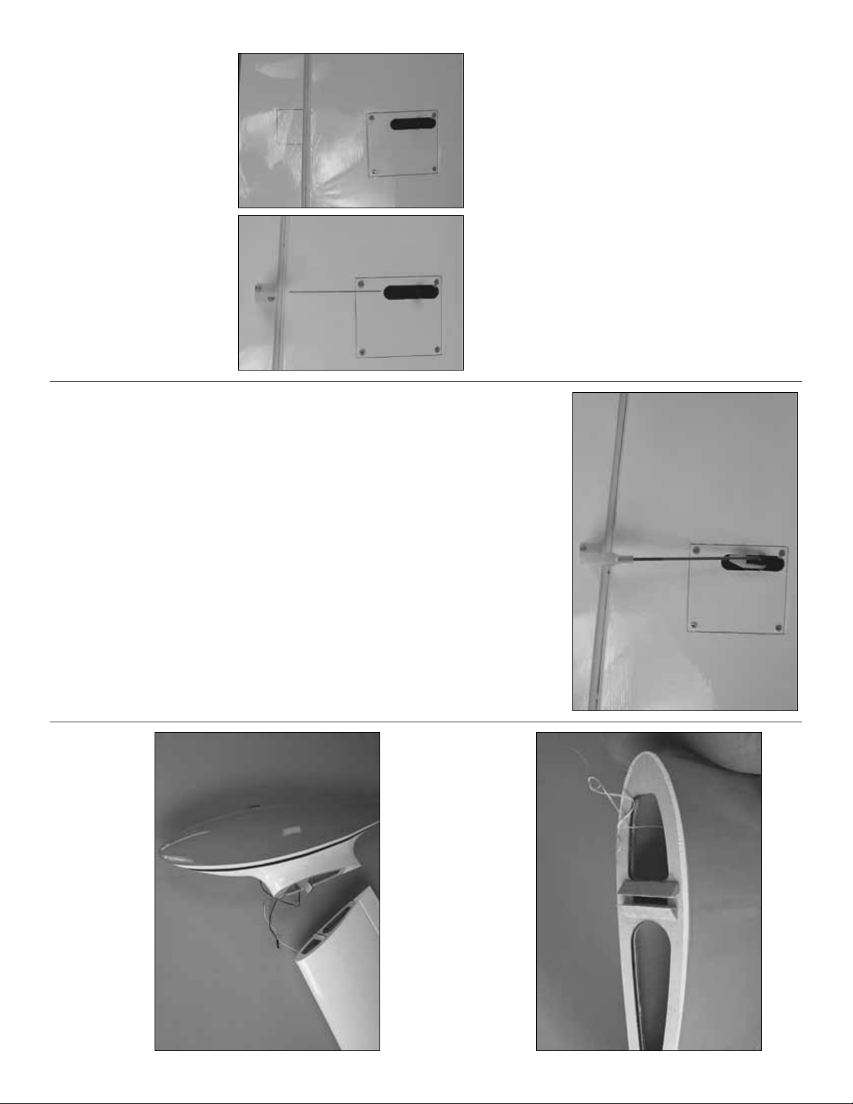
❏❏1. Cut two airlines to a length of 24" [610mm].
They need to be fed from the wheel well to the center
of the wing where they will be pulled through the
wing with the string that was left in place during the
servo installation. The lines can be fed through the
openings for the servo leads as shown in the photos.
Once the line is installed between the wheel well and
the wing, tie the string to the two airlines and pull
them through the hole at the root of the wing.
❏❏2. Attach the airlines to the air inlets on the
landing gear.Place the landing gear onto the landing
gear rails. (
Note: When installing the landing gear,
the torque link assembly will be towards the back of
the wing.
) Drill a 7/64" [2.8mm] hole through the
landing gear plate for each of the mounting holes.
Insert and then remove a #6 x 1/2" [13mm] screw
into each hole.Apply a small amount of thin CA onto
the threads to harden them. After the glue has
hardened, mount the landing gear with a #6 x 1/2"
[13mm] screw, #6 flat washer and #6 lock washer.
❏❏3. Cut away the wood as shown.
❏❏4. Loosen the set screw for the landing gear.
Remove the landing gear leg.Then, slide one of the
landing gear door cover mounting brackets onto the
leg. Reinstall the leg and tighten the set screw.
❏❏5. Retract the landing gear.Then, position the
landing gear door so it is centered in the opening as
shown. Make a line on the door in line with the hole
in the landing gear.
- 23 -
Page 24

❏❏6. Place a piece of masking tape onto the
mounting flange. Make a line on the masking tape in
line with the hole in the landing gear.
❏❏7. Position the landing gear door in the opening
in the bottom of the wing.When you are satisfied with
the position of the door, draw a line across the line
already drawn on the landing gear door.
❏❏8.At the intersection of the two lines drill a 1/16"
[1.6mm] pilot hole. Then drill through the pilot hole
with a 11/64" [4.4mm] drill.
❏❏9. Glue two #8 flat washers to the inside of the
landing gear door.
❏❏10. Locate a #8 x 1" [25mm] phillips head
machine screw. Use a high speed motor tool or
hacksaw and cut the bolt so the threaded length of
the bolt is 5/16" [7.9mm].
❏❏11. Locate the 4-40 x 12" [305mm] threaded
rod. File a point onto one end of the rod. Cut the
pointed end from the rod to a length of 1/4" [6mm].
❏❏12.Position the landing gear door cover mounting
bracket so that it is appro ximately 1/16" [1.6mm] abov e
the torque link assembly. Install the pointed rod into the
hole in the bracket as shown.Be sure the flat portion of
the bracket is aligned with the surface of the wing and
then tighten the threaded rod against the landing gear.
❏❏13. Place the landing gear door in position over
the wheel well. Install the 8-32 bolt that you cut
through the hole in the gear door, tightening it to the
landing gear. Adjust the door as needed to make
sure it is properly centered in the wheel well. Once
you are satisfied with the position, press firmly on the
landing gear door where the pointed rod is making
contact with the door.Press firmly enough to make a
small mark on the inside of the door.
- 24 -
Page 25

❏❏14.Remove the gear door from the landing gear.
On the mark you made drill a 1/16" [1.6mm] pilot hole
through the mark. Drill though the pilot hole with a
7/64" drill bit.
❏❏15. Reinstall the landing gear door onto the
landing gear with the 8-32 bolt. Using a 4-40 x 1/4"
[13mm] socket head cap screw and a #4 washer,
secure the bottom of the door to the landing gear
door cover mounting bracket. Be sure to use thread
locker on both mounting screws.
❏❏16. Position the landing gear flange plate over
the landing gear mounting plate.Drill a 1/16" [1.6mm]
hole in each corner of the plate. Remove the flange
plate from the wing and drill a 3-32" [2.4mm] hole
through each of the holes you drilled in the flange
plate.Secure the flange plate to the wing with four #2
x 3/8" [10mm] screws and #2 flat washers.
❏ 17. Repeat steps 1-16 for the other landing gear.
Install the Retract Hardware
❏ 1.Glue the plywood air control valve plate to the
servo tray and glue the two plywood triangle shaped
gussets as shown.
❏ 2. Install a ball link ball to the control valve with a
.080 nut. Be sure to use a small amount of thread
locker when securing the nut. Insert the air control
valve into the plate.Secure the valve to the plate with
the nut.Be sure to use a small amount of thread locker
when securing the nut.
❏ 3. Install the retract servo into the servo opening
in the tray. Secure it the same way you did the other
servos. Install a nylon ball link onto the 2-56 x 6"
[152mm] threaded rod approximately 15 turns.Then
install the nylon ball link onto the ball. Center the air
control valve arm and center the servo.With a fine tip
marker, mark the wire where it aligns with the outer
hole of the servo arm. Make a 90 degree bend on the
mark. Cut the wire so the wire is 3/8" [10mm] in
length after the bend. Inser t the wire into the servo
arm and lock it in place with a nylon Faslink.
- 25 -
Page 26

❏ 4. Decide on a location to mount the air fill valve.
We mounted ours on the bottom of the fuselage just
behind the trailing edge of the wing. This keeps the
valve somewhat hidden but it is not the most easily
accessible location.If you do not mind it being visible
you may wish to locate in on the fuselage in a place
more convenient for filling the air tank.
❏ 5. Install the air lines to the air tank, fill valve and
air control valve as shown in the instructions that
came with the air control kit. Install the connectors
that will connect the airlines from the main gear to
the airlines in the fuselage.
❏ 6. You now have to make a couple of decisions
regarding the wing.The wing is designed in two pieces
for easier transportation and storage. Those of you
that have an appropriately sized v ehicle and adequate
storage area may wish to leav e the wing assemb led in
one piece.If you will be leaving the wing together, join
the two air lines that will retract the landing gear with
a “T” fitting. Join the remaining two lines with another
“T” fitting. Install a 12" [310mm] length of air line onto
the “T” fitting and an air line quick connector on the
other end. If you will be taking your wings apart,
substitute a pair of quick connectors for the “T”fittings.
FINAL ASSEMBLY
Completing the Radio Installation
❏ 1. Connect the elevator and rudder servos to the
receiver. If you have installed retracts, connect the
retract servo to the receiver too.
❏ 2. You have a few options when connecting the
aileron, flap and throttle servos. Depending on the
number of channels you hav e available on your radio
system, you may wish to have each servo lead plug
into its own receiver slot. If you choose to do this
follow the instructions included with your radio
system. The option of using a “Y” connector is
probably the simplest method.Install a “Y” connector
between the two aileron connections coming out of
each wing and one between the flap connections in
each wing.If you intend to leave y our wings together,
secure the connectors together with heat shrink
tubing, tape or some other method. If you want the
ability to separate the two wings, secure the
connectors on one wing only.
❏ 3. For the throttle linkage you can use “Y”
connectors the same way done for the ailerons and
flaps. Again, if your radio has the ability to plug each
throttle servo into its own slot, you might want to
consider doing this. Even if you chose to use “Y”
connectors on the ailerons and flaps, you might want
to have the throttles on separate channels and mix
them with the radio.This would give you the option of
starting and operating each engine independently of
each other during the start up of the engines.
❏ 4. Install a 6" [152mm] ser vo extension into the
slots in your receiver for each of the aileron, flap and
throttle servo leads. This will make plugging the
connections in the wing to the receiver easier.
❏ 5. Install the radio switch and charge jack for your
particular brand of radio and plug it into the receiver.
We chose to mount ours on the bottom of the
fuselage. For easier access you might want to
consider mounting it to the side of the fuselage.
Connect the Lighting System
The lighting system is a nice scale option but is not
required in order to fly the airplane. If you choose not
to use the lights you can skip this section of the
manual.
Do not operate the lighting system from
the receiver battery pack!
The lighting system will
require the use of a separate 500 mAh battery pack
and a switch harness for installation.
- 26 -
Page 27

❏ 1. You may wish to balance your airplane before
deciding on the final location of the battery for the lighting
system, but most likely the battery placement will not be
crucial for purposes of balancing the airplane.Mount the
battery for the lighting system on the opposite side of the
battery/receiver tray from the battery for the radio
system. Use the plastic tie wraps to hold them in place.
❏ 2. Install a switch and charge jack on the fuselage
the same way done for the receiver.
❏ 3. Be sure the main landing light from the front of
the fuselage is plugged into the pre-installed lighting
harness. Plug the wires from the switch into the
wiring harness and the batter y pack.
❏ 4. Once everything in the fuselage is connected
properly, use tie wraps or tape to bundle the excess
wire together to help clean up the entire installation.
When doing this be sure that you leave the male
connector for the lights in the wing accessible.
❏ 5.Install a “Y”harness to the wires from the left and
right wing tip light. When you assemble the airplane
for flight, plug the lights from the wing into the
connector on the lighting harness.
Apply the Decals
1. Use scissors or a sharp hobby knife to cut the
decals from the sheet.
2. Be certain the model is clean and free from oily
fingerprints and dust. Prepare a dishpan or small
bucket with a mixture of liquid dish soap and warm
water–about one teaspoon of soap per gallon of water .
Submerse the decal in the soap and water and peel off
the paper backing.Note: Even though the decals have
a “sticky-back” and are not the water transfer type,
submersing them in soap and water allows accurate
positioning and reduces air bubbles underneath.
3. Position the decal on the model where desired.
Holding the decal down, use a paper towel to wipe
most of the water away.
4. Use a piece of soft balsa or something similar to
squeegee remaining water from under the decal.
Apply the rest of the decals the same way.
GET THE MODEL READY TO FLY
Check the Control Directions
❏ 1.Turn on the transmitter and receiver and center
the trims. If necessary, remove the servo arms from
the servos and reposition them so they are centered.
Reinstall the screws that hold on the servo arms.
❏ 2. With the transmitter and receiver still on, check
all the control surfaces to see if they are centered.If
necessary, adjust the clevises on the pushrods to
center the control surfaces.
❏ 3. Make cer tain that the control surfaces and the
carburetor respond in the correct direction as shown
in the diagram. If any of the controls respond in the
wrong direction, use the servo reversing in the
transmitter to reverse the servos connected to those
controls. Be certain the control surfaces have
remained centered. Adjust if necessar y.
- 27 -
Page 28

Set the Control Throws
Use a Great Planes AccuThrow
™
(or a ruler) to
accurately measure and set the control throw of each
control surface as indicated in the chart that follows.If
your radio does not have dual rates, we recommend
setting the throws at the high rate setting. NOTE: The
throws are measured at the widest part of the
elevators, rudder and ailerons.
Balance the Model (C.G.)
At this stage the model should be in ready-to-fly
condition with all of the systems in place including
the engines, landing gear and the radio system.
❏ 1. Use a felt-tip pen or 1/8" [3mm]-wide tape to
accurately mark the C.G. on the top of the wing on
both sides of the fuselage.The C.G. is located 3-7/16"
[87mm] back from the leading edge of the wing at the
fuselage sides.
❏ 2.With the wing attached to the fuselage, all parts
of the model installed (ready to fly) and an empty fuel
tank, place the model upsidedown on a Great Planes
CG Machine
™
, or lift it upside down at the balance
point you marked.
❏ 3.If the tail drops, the model is “tail heavy”and the
battery pack and/or receiver must be shifted forward
or weight must be added to the nose to balance.If the
nose drops, the model is “nose heavy”and the battery
pack and/or receiver must be shifted aft or weight
must be added to the tail to balance. If possible,
relocate the battery pack or eliminate any additional
ballast required. Use Great Planes (GPMQ4485)
“stick on” lead. A good place to add stick-on nose
weight is in the nose of the fuselage.Begin by placing
incrementally increasing amounts of weight on the
inside of the fuse until the model balances. Once you
have determined the amount of weight required, it
can be permanently attached. If required, tail weight
may be added inside the rear of the fuselage.
❏ 4. IMPORTANT: If you found it necessary to add
any weight, recheck the C.G. after the weight has
been installed.
Balance the Model Laterally
❏ 1. With the wing level, have an assistant help you
lift the model at the tip of the nose and the tail. Do
this several times.
❏ 2.If one wing always drops when you lift the model,
it means that side is heavy. Balance the airplane by
adding weight to the other wing tip.An airplane that
has been laterally balanced will track better in
loops and other maneuvers.
This is where your model should balance for the first
flights.Later, you may wish to experiment by shifting
the C.G. up to 5/16" [8mm] forward or 5/16" [8mm]
back to change the flying characteristics.Moving the
C.G. forward may improve the smoothness and
stability, but the model may then require more speed
for takeoff and make it more difficult to slow for
landing. Moving the C.G. aft makes the model more
maneuverable , but could also cause it to become too
difficult to control. In any case, start at the
recommended balance point and do not at any
time balance the model outside the specified range.
More than any other factor, the C.G. (balance
point) can have the greatesteffect on how a model
flies, and may determine whether or not your first
flight will be successful.If you value this model and
wish to enjoy it for many flights, DO NOT
OVERLOOK THIS IMPORTANT PROCEDURE. A
model that is not properly balanced will be
unstable and possibly unflyable.
IMPORTANT:The Cessna 310 has been extensively
flown and tested to arrive at the throws at which it flies
best. Flying your model at these throws will provide
you with the greatest chance for successful first flights .
If, after you have become accustomed to the way the
Cessna 310 flies, you would like to change the thro ws
to suit your taste, that is fine. However, too much
control throw could make the model difficult to control,
so remember, “more is not always better.”
These are the recommended control surface throws:
High Rate Low Rate
ELEVATOR 1" up 3/4" up
1" down 3/4" down
[25mm] [19mm]
RUDDER 1-1/2" right 1" right
1-1/2" left 1" left
[38mm] [25mm]
AILERONS: 3/4" up 1/2" up
3/4" down 1/2" down
[19mm] [19mm]
FLAPS: 1-5/8" [40mm] down
- 28 -
3-7/16" [87mm]
Page 29

Adjusting the Retractable Landing Gear
After connecting the air lines as instructed in the
instructions that came with the Air Control kit, fill the
air tank to 100psi and try cycling the landing gear.
The landing gear should cycle up and down freely. If
they do not, here are some troubleshooting tips:
❏ 1. The gear does not move up or down: Check to
be sure the control screws on the variable rate valve
are open.
❏ 2. The landing gear moves up and down but is
not smooth:When mounting the landing gear onto the
landing gear rails it is important that the rails are
exactly parallel to one another. If not, when you tighten
the screws the mounting flange of the gear mechanism
can twist slightly.Try loosening the mounting screws a
little and try cycling the landing gear again. If the gear
now works, re-tighten the screws one at a time, cycling
the gear after each screw is tightened.When you find
out which screw is pulling down too hard on the
mounting flange, slip a shim under the mounting flange
and then re-tighten the screw.
❏ 3. One of the landing gear goes up while the
other goes down: Most likely you have crossed one of
the air lines.
❏ 4. The main landing gear seems to lock in the
“gear up”position: The screw that you cut to length
to hold the bottom of the landing gear door to the
strut can extend too far into the thread, causing the
gear to bind. Slightly loosen that screw and try
cycling the gear again.If it now works smoothly grind
a little off the end of the bolt.
PREFLIGHT
Identify Y our Model
No matter if you fly at an AMA sanctioned R/C club
site or if you fly somewhere on your own, you should
always have your name, address, telephone number
and AMA number on or inside your model. It is
required at all AMA R/C club flying sites and AMA
sanctioned flying events. Fill out the identification tag
on page 35 and place it on or inside your model.
Charge the Batteries
Follow the battery charging instructions that came with
your radio control system to charge the batteries.You
should always charge your transmitter and receiver
batteries the night before you go flying, and at other
times as recommended by the radio manufacturer.
Balance Propellers
Carefully balance your propellers and spare propellers
before you fly. An unbalanced prop can be the single
most significant cause of vibration that can damage
your model.Not only will engine mounting screws and
bolts loosen, possibly with disastrous effect, but
vibration may also damage your radio receiver and
battery. Vibration can also cause your fuel to foam,
which will, in turn, cause your engine to run hot or quit.
We use a Top Flite Precision Magnetic Prop Balancer
(TOPQ5700) in the workshop and keep a Great
Planes Fingertip Prop Balancer (GPMQ5000) in our
flight box.
Ground Check
If the engine is new, follow the engine
manufacturer’s instructions to break-in the
engine. After break-in, confir m that the engine idles
reliably, transitions smoothly and rapidly to full power
and maintains full power–indefinitely. After you run
the engine on the model, inspect the model closely
to make sure all screws remained tight, the hinges
are secure, the prop is secure and all pushrods and
connectors are secure.
CAUTION: Unless the instr uctions that came with
your radio system state differently, the initial
charge on new transmitter and receiver batteries
should be done for 15 hours using the slow-
charger that came with the radio system. This
will “condition” the batteries so that the next
charge may be done using the fast-charger of y our
choice. If the initial charge is done with a fast-
charger, the batteries may not reach their full
capacity and you may be flying with batteries that
are only partially charged.
- 29 -
Page 30

Range Check
Ground check the operational range of your radio
before the first flight of the day. With the transmitter
antenna collapsed and the receiver and transmitter
on, you should be able to walk at least 100 feet away
from the model and still have control. Have an
assistant stand by your model and, while you w ork the
controls, tell you what the control surfaces are doing.
Repeat this test with the engines running at various
speeds with an assistant holding the model, using
hand signals to show you what is happening. If the
control surfaces do not respond correctly, do not fly!
Find and correct the problem first.Look for loose servo
connections or broken wires, corroded wires on old
servo connectors, poor solder joints in your battery
pack or a defectiv e cell, or a damaged receiver crystal
from a previous crash.
ENGINE RUN IN INSTRUCTIONS
Because of the importance for both engines to run
through the entire flight we recommend that you
follow these engine pre-flight instructions.
1. Before attempting to fly the airplane, remove the
nacelles and run a full tank of fuel through one
engine. Put a second tank of fuel through the same
engine, running it at different speeds from idle to full
throttle. It is impor tant that the engine has a solid,
reliable idle and that it transitions from idle to mid
range and then full throttle without any signs of the
engine quitting. Adjust the low speed needle valve to
achieve a good idle and low end transition. Then
adjust the high speed needle valve. Once you are
confident of the engine performance, repeat the
procedure for the other engine.
2.Once you are satisfied with both engines, carefully
start both of them. When starting a twin engine
airplane be careful not to get anything or any part of
you in the prop of the running engine! With both
engines running, let them idle for a few seconds.
Check the RPM of each engine. They should be
close but not necessarily exactly the same.Advance
the throttle to full. The engines should transition
similarly .Once at full throttle the engines should have
an RPM very close to one another.Check this with a
tachometer.If you do not have a tachometer listen to
the sound of the engines. When they are running
close to the same RPM they will sound the same.
Run the two engines together for the remainder of
the tank, running them throughout the engine range.
3. Reinstall the nacelles and run the engines. A fully
cowled engine may run at a higher temperature than
an un-cowled engine.Adjust the needle valves so the
engines run as well with the nacelles as they did
when the nacelles were off. Check the RPM
measurements, making sure the engines are
synchronized with each other. Once you have the
engines adjusted to their maximum RPM, richen the
engines, allowing the engines to run 150–200 RPM
below the maximum achievable RPM. Running the
engine slightly rich will help allow the engines to run
slightly cooler and minimize chances of the engines
overheating. When making your final engine
adjustments it is most important that the engines are
synchronized at full throttle.At lower RPM it is not as
crucial that they are in synch. If, when your engines
are at full throttle one engine has a higher RPM than
another, richen the stronger engine until it is in synch
with the weaker engine.
4.It has been our experience that the .46 AX engines
will run approximately 10 minutes with the supplied
fuel tanks. We recommend that you run the engines
on the ground at 3/4 to full throttle and time them to
see how long you can expect them to run while in the
air. Use of a timer in flight will assure that you don’t
lose track of time.
ENGINE SAFETY PRECAUTIONS
• Keep all engine fuel in a safe place, a wa y from high
heat, sparks or flames, as fuel is very flammable.
Do not smoke near the engine or fuel; and
remember that engine exhaust gives off a great
deal of deadly carbon monoxide.Therefore do not
run the engine in a closed room or garage.
• Get help from an experienced pilot when learning
to operate engines.
• Use safety glasses when starting or running engines.
• Do not run the engine in an area of loose gravel or
sand; the propeller may throw such material in
your face or eyes.
• Keep your face and body as well as all spectators
away from the plane of rotation of the propeller as
you start and run the engine.
• Keep these items away from the prop: loose
clothing, shirt sleeves, ties, scarfs, long hair or
loose objects such as pencils or screwdrivers that
may fall out of shirt or jacket pockets into the prop.
• Use a “chicken stick” or electric star ter to star t the
engine.Do not use your fingers to flip the propeller.
Make certain the glow plug clip or connector is
secure so that it will not pop off or otherwise get
into the running propeller.
• Make all engine adjustments from behind the
rotating propeller.
• The engine gets hot! Do not touch it during or right
after operation. Make sure fuel lines are in good
condition so fuel will not leak onto a hot engine,
causing a fire.
• To stop a glow engine, cut off the fuel supply by
closing off the fuel line or following the engine
manufacturer’s recommendations. Do not use
hands, fingers or any other body part to try to stop
the engine.Do not throw anything into the propeller
of a running engine.
Failure to follow these safety precautions may
result in severe injury to yourself and others.
- 30 -
Page 31

AMA SAFETY CODE (EXCERPTS)
Read and abide by the following excerpts from the
Academy of Model Aeronautics Safety Code.For the
complete Safety Code refer to Model Aviation
magazine, the AMA web site or the Code that came
with your AMA license.
General
1) I will not fly my model aircraft in sanctioned
events, air shows, or model flying demonstrations
until it has been proven to be airworthy by having
been previously, successfully flight tested.
2) I will not fly my model aircraft higher than
approximately 400 feet within 3 miles of an airport
without notifying the airport operator. I will give
right-of-way and av oid flying in the proximity of full-
scale aircraft.Where necessary, an observer shall
be utilized to supervise flying to avoid having
models fly in the proximity of full-scale aircraft.
3) Where established, I will abide by the safety rules
for the flying site I use, and I will not willfully and
deliberately fly my models in a careless, reckless
and/or dangerous manner.
5) I will not fly my model unless it is identified with my
name and address or AMA number, on or in the
model. Note:This does not apply to models while
being flown indoors.
7) I will not operate models with pyrotechnics (any
device that explodes , b urns, or propels a projectile
of any kind).
Radio Control
1) I will have completed a successful radio
equipment ground check before the first flight of a
new or repaired model.
2) I will not fly my model aircraft in the presence of
spectators until I become a qualified flier, unless
assisted by an experienced helper.
3) At all flying sites a straight or curved line(s) must
be established in front of which all flying takes
place with the other side for spectators. Only
personnel involved with flying the aircraft are
allowed at or in the front of the flight line.Intentional
flying behind the flight line is prohibited.
4) I will operate my model using only radio control
frequencies currently allowed by the Federal
Communications Commission.
5) I will not knowingly operate my model within three
miles of any pre-existing flying site except in
accordance with the frequency sharing agreement
listed [in the complete AMA Safety Code].
9) Under no circumstances may a pilot or other person
touch a powered model in flight; nor should any part
of the model other than the landing gear, intentionally
touch the ground, except while landing.
IMAA SAFETY CODE (EXCERPTS)
Since the Cessna 310 qualifies as a “giant scale”
model and is therefore eligible to fly in IMAA
events, we’ve printed excerpts from the IMAA
Safety Code which follows.
What is Giant Scale?
The concept of large or giant-scale is generally
considered to apply to radio controlled model aircraft
with minimum wingspans of 80 inches for monoplanes
and 60 inches for multi-wing aircraft.Quarter-scale or
larger replicas of person-carrying aircraft with proper
documentation (minimum 3-view drawing) which do
not fit the size requirements will also be permitted.
Section 1.0: SAFETY STANDARD
1.1 Adherence to Code: The purpose of this Safety
Code is to provide a structure whereby all
participants, including spectators, will be aware of
the inherent dangers in the operation of radio
controlled aircraft.This code is meant to serve as a
minimum guideline to all participants. It is
understood that the ultimate responsibility for the
safety of any aircraft lies with the owner(s), pilot(s)
and spectator(s) involved in any event. It is the
responsibility of all participants to exercise caution
when operating, or observing the operation of all
radio controlled aircraft. The pilot/owner of an
aircraft will not be dissuaded from taking whatever
steps they deem necessary, in addition to this
code, to insure that their aircraft is safe.
1.2 The most current AMA Safety Code in effect is to
be observed.
Section 3.0: SAFETY REVIEW
3.4 Flight Testing: All aircraft are to have been flight
tested and flight trimmed with a minimum of six
(6) flights before the model is allowed to fly at an
IMAA Sanctioned event.
3.5 Proof of Flight: The completing and signing of the
Declaration section of the Safety Re view f orm (see
Section 3.2) by the pilot (or owner) shall
document, as fact, that the noted aircraft has been
successfully flight tested and proven airworthy
prior to the IMAA event.
Section 4.0: SPOTTER/HELPER
4.1 Spotter/Helper Definition: An assistant to aid the
pilot during start-up, and taxing onto the runway.
The spotter/helper will assist the pilot in completing
a safe flight.
4.2 Each pilot is required to have a spotter/helper at all
IMAA sanctioned events. The event Safety
Committee should be prepared to assist those
pilots who do not have a spotter/helper to make
sure that every registered pilot has the opportunity
to fly at a sanctioned event.
- 31 -
Page 32

Section 5.0: EMERGENCY ENGINE SHUT OFF
(Kill Switch)
5.1 Magneto spark ignition engines must have a coil-
grounding switch on the aircraft to stop the engine.
This will also prevent accidental starting of the
engine.This switch shall be readily available to both
pilot and spotter/helper.This switch is to be oper ated
manually and without the use of the Radio System.
5.2 Engines with battery powered ignition systems
must have a switch to turn off the power from the
battery pack to disable the engine from firing.This
will also prevent accidental starting of the engine.
This switch shall be readily available to both pilot
and spotter/helper. This switch shall be operated
manually and without the use of the Radio System.
5.3 There must also be a means to stop the engine from
the transmitter. The most common method is to
completely close the carburetor throat using throttle
trim. However, other methods are acceptable. This
requirement applies to all glow/gas ignition engines
regardless of size.
Section 6.0: RADIO REQUIREMENTS
6.1 All transmitters must be FCC type certified.
6.2 FCC Technician or higher-class license required
for 6 meter band operation only.
ADDITIONAL IMAA GENERAL
RECOMMENDATIONS
The following recommendations are included in the
Safety Code not to police such items, but rather to
offer basic suggestions for enhanced safety. It is
expected that IMAA members will av ail themselves of
technological advances as such become available, to
promote the safety of all aircraft and participants.
• Servos need to be of a rating capable to handle the
loads that the control surfaces impose upon the
servos. Standard servos are not recommended for
control surfaces.Serv os should be rated hea vy-duty
ounces of torque. For flight critical control functions
a minimum of 45 inch/ounces of torque should be
considered. This should be considered a minimum
for smaller aircraft and higher torque servos are
strongly encouraged for larger aircraft. The use of
one servo for each aileron and one for each
stabilizer half is strongly recommended.Use of dual
servos is also recommended on larger aircraft.
• On board batteries should be, at a minimum, 1000
mAh up to 20 lbs., 1200 mAh to 30 lbs., 1800 mAh
to 40 lbs., and 2000 mAh over 40 lbs. flying weight.
The number and size of servos, size and loads on
control surfaces, and added features should be
considered as an increase to these minimums.
Batteries should be able to sustain power to the
onboard radio components for a minimum of one
hour total flying time before recharging.
• Dependable, redundant and f ail saf e battery systems
are recommended.
• The use of anti-glitch devices for long leads
is recommended.
• There is no maximum engine displacement limit, as it
is the position of this body that an under powered
aircraft presents a greater danger than an over
powered aircraft. However, the selections of engine
size relative to airframe strength and power loading
mandates good discretionary judgment by the
designer and builder. Current AMA maximums for
engine displacement are 6.0 cu.in.for two stroke and
9.6 cu. in. for four stroke engines. These maximums
apply only to AMA Sanction competition events such
as 511, 512, 515 and 520.All non competition events
should be sanctioned as Class C events, in which
these engine size maximums do not apply.
• Generally, it is recommended that no attempt should
be made to fly a radio controlled model aircraft with
a gasoline engine in which the model aircraft weight
would exceed 12 pounds per cubic inch of engine
displacement (under powered), or be less than 5
pounds per cubic inch of engine displacement
(overpowered).Example: Using a 3 cu. in. engine, a
model would likely be under powered at an aircraft
weight greater than 36 pounds. With the same
engine, an aircraft weighing less than 15 pounds
would likely be over powered.
• Servo arms and control horns should be rated heavy-
duty. Glass filled servo arms and control horns are
highly recommended.
• Control surface linkages are listed in order
of preference:
1. Cable system (pull pull). A tiller bar is highly
recommended along with necessary bracing.
2.Arrow-shaft, fiberglass or aluminum, 1/4" or 5/16"
OD. Bracing every six (6) to ten (10) inches is
highly recommended.
3. Tube in tube (Nyrod). Bracing every few inches
is highly recommended. Inner tube should be
totally enclosed in outer tube.
4. Hardwood dowel, 3/8" OD. Bracing every six
(6) to ten (10) inches is highly recommended.
• Hinges should be rated heavy-duty and manufactured
primarily for use in giant-sized aircraft. Homemade
and original design hinges are acceptable if
determined to be adequate for the intended use.
• Clevis (steel, excluding heavy-duty ball links) and
attachment hardware should be heavy-duty 4-40
thread-and-rod type.2-56 thread size rod is acceptable
for some applications (e.g.throttle).Clevises must have
lock nuts and sleeve (fuel tubing) or spring keepers.
• Propeller tips should be painted or colored in a visible
and contrasting manner to increase the visibility of the
propeller tip arc.
- 32 -
Page 33

CHECK LIST
❏ 1. Fuelproof all areas exposed to fuel or exhaust
residue such as the cowl ring, cowl mounting
blocks, wing saddle area, etc.
❏ 2. Check the C.G.according to the measurements
provided in the manual.
❏ 3. Be certain the battery and receiver are securely
mounted in the fuse. Simply stuffing them into
place with foam rubber is not sufficient.
❏ 4. Extend your receiver antenna and make sure it
has a strain relief inside the fuselage to keep
tension off the solder joint inside the receiver.
❏ 5. Balance your model
laterally
as explained in
the instructions.
❏ 6. Use threadlocking compound to secure critical
fasteners such as the set screws that hold the
wheel axles to the struts, screws that hold the
carburetor arm (if applicable), screw-lock
pushrod connectors, etc.
❏ 7. Add a drop of oil to the axles so the wheels will
turn freely.
❏ 8. Make sure all hinges are securely glued in place.
❏ 9. Reinforce holes for wood screws with thin CA
where appropriate (servo mounting screws,
cowl mounting screws, etc.).
❏ 10.Confir m that all controls operate in the correct
direction and the throws are set up according
to the manual.
❏ 11. Make sure there are silicone retainers on all
the clevises and that all servo arms are
secured to the servos with the screws included
with your radio.
❏ 12.Secure connections between ser vo wires and
Y-connectors or servo extensions, and the
connection between your battery pack and the
on/off switch with vinyl tape, heat shrink tubing
or special clips suitable for that purpose.
❏ 13.Make sure any servo extension cords you may
have used do not interfere with other systems
(servo arms, pushrods, etc.).
❏ 14.Secure the pressure tap (if used) to the muffler
with high temp RTV silicone, thread locking
compound or J.B.Weld.
❏ 15. Make sure the fuel lines are connected and
are not kinked.
❏ 16. Balance your propeller (and spare propellers).
❏ 17.Tighten the propeller nut and spinner.
❏ 18.Place your name, address, AMA number and
telephone number on or inside your model.
❏ 19.Cycle your receiver battery pack (if necessary)
and make sure it is fully charged.
❏ 20. If you wish to photograph your model, do so
before your first flight.
❏ 21. Range check your radio when you get to the
flying field.
FLYING
The Cessna 310 is a great-flying model that flies
smoothly and predictably. The Cessna 310 does not,
howev er, possess the self-recovery characteristics of
a primary R/C trainer and should be flown only by
experienced R/C pilots.
CAUTION (THIS APPLIES TO
ALL
R/C
AIRPLANES): If, while flying, you notice an alarming
or unusual sound such as a low-pitched “buzz,” this
may indicate control surface flutter. Flutter occurs
when a control surface (such as an aileron or elev ator)
or a flying surface (such as a wing or stab) rapidly
vibrates up and down (thus causing the noise). In
extreme cases, if not detected immediately, flutter can
actually cause the control surface to detach or the
flying surface to fail, thus causing loss of control
followed by an impending crash.The best thing to do
when flutter is detected is to slow the model
immediatelyby reducing power , then land as soon as
safely possible.Identify which surface fluttered (so the
problem may be resolved) by checking all the servo
grommets for deterioration or signs of vibration.Make
certain all pushrod linkages are secure and free of
play. If it fluttered once, under similar circumstances it
will probably flutter again unless the problem is fixed.
Some things which can cause flutter are; Excessive
hinge gap; Not mounting control horns solidly; P oor fit
of clevis pin in horn; Side-play of wire pushrods
caused by large bends; Excessive free play in servo
gears; Insecure servo mounting;and one of the most
prevalent causes of flutter; Flying an over-powered
model at excessive speeds.
During the last few moments of preparation your
mind may be elsewhere anticipating the e xcitement
of the first flight. Because of this, you may be more
likely to overlook certain checks and procedures
that should be performed before the model is flown.
To help avoid this, a check list is provided to make
sure these important areas are not overlooked.
Many are covered in the instruction manual, so
where appropriate, refer to the manual f or complete
instructions. Be sure to check the items off as they
are completed.
- 33 -
Page 34

Takeoff
Before you get ready to takeoff, see how the model
handles on the ground by doing a few practice runs
at low speeds on the runway. If necessary, adjust
the nose wheel so the model will roll straight down
the runway. If you need to calm your nerves before
the maiden flight, shut the engines down and bring
the model back into the pits.If you have been running
the engines for any extended period of time prior to
takeoff, top off the fuel, and then check all fasteners
and control linkages for peace of mind.
If you are taking off from an asphalt runway there is no
need to use flaps for takeoff. If you are taking off from
grass you will not need to use flaps as long as you
allow the plane to gain adequate ground speed.If you
have a short grass field, if it has particularly thick grass
or rough conditions you might consider applying 1/2"
[13mm] to 3/4" [19mm] of flap.When the plane breaks
ground be sure to maintain a shallow climb out and
retract the flaps as the plane begins to pick up speed.
When you’re ready, remember to takeoff into the wind
and point the model straight down the runway. As the
model gains speed begin adding elevator to achieve a
smooth take-off.Gain as much speed as your runway
and flying site will practically allow before gently
applying up elevator, lifting the model into the air. At
this moment it is likely that you will need to apply more
right rudder to counteract engine torque. Be smooth
on the elevator stic k, allowing the model to establish a
gentle climb to a safe altitude before turning into the
traffic pattern.
Flight
For reassurance and to keep an eye on other traffic,
it is a good idea to have an assistant on the flight line
with you.Tell him to remind you to throttle back once
the plane gets to a comfortable altitude. While full
throttle is usually desirable for takeoff, this model
flies more smoothly at reduced speeds.
Take it easy for the first few flights, gradually getting
acquainted with it as you gain confidence.Adjust the
trims to maintain straight and level flight. After flying
around for a while, and while still at a safe altitude
with plenty of fuel, practice slow flight and execute
practice landing approaches utilizing the flaps. You
will find that the plane may balloon slightly when the
flaps are deployed.A small amount of down elevator
will minimize this and as the plane slows the
ballooning will stop. You may wish to mix in 1 to 2
degrees of down elevator to the flaps but it is best to
work on the amount of mix after the first flight.
Continue to fly around, ex ecuting various maneuvers
and making mental notes (or having your assistant
write them down) of what trim or C.G. changes may
be required to fine tune the model so it flies the way
you like. Mind your fuel level, use this first flight to
become familiar with your model before landing.
Landing
To initiate a landing approach, lower the throttle while
on the downwind leg and lower the flaps.When the
flaps are deployed you will find that the plane may
balloon slightly. A small amount of down elevator will
minimize this and as the plane slows the ballooning
will stop. You may wish to mix in 1 to 2 degrees of
down elev ator to the flaps but it is best to w ork on the
amount of mix after the first flight. Allow the nose of
the model to pitch downward to gradually bleed off
altitude. Continue to lose altitude, but maintain
airspeed by keeping the nose down as you turn onto
the crosswind leg. Make your final turn toward the
runway (into the wind) keeping the nose down to
maintain airspeed and control. Level the attitude
when the model reaches the runway threshold,
modulating the throttle as necessary to maintain your
glide path and airspeed. If you are going to
overshoot, smoothly advance the throttle (always
ready on the right rudder to counteract torque) and
climb out to make another attempt. When you’re
ready to make your landing flare and the model is a
foot or so off the deck, smoothly increase up ele vator
until it gently touches down.
Engine Out Procedure
One of the primary concerns everybody has when
thinking about flying a twin-engine airplane is “what if
an engine quits?” While this is never a desirable
situation, through our previous flying experience with
other twin-engine models and our flight testing and
development with this Cessna 310, we have
developed a model that will not suddenly react
unexpectedly if an engine quits and can be controlled
well enough to get her safely back to the ground.
Thankfully, during straight-and-level flight, if an
engine does quit the plane will not do anything
sudden or unexpected.The first thing you must do is
recognize that an engine has quit and then
determine which engine it is. When an engine does
quit the plane will gradually yaw towards the dead
engine and will soon begin to lose altitude. At this
point you must decide if you are going to try and land
on one engine or kill the other engine and attempt a
dead-stick landing.We have flown left and right hand
turns on a single engine, turning into both the dead
engine as well as the engine that is running. Both
situations will require the use of the ailerons and the
rudder. The key to making the turns on a single
engine is to steer the plane with the rudder and use
the ailerons to keep the wings level.Turning with just
the ailerons can result in a stall or a spin depending
on which engine you turn into.
Turning towards the running engine will result in a tight
turn so it is important to tr y and make a flat, gradual
turn, making the turn with rudder input and keeping
the wings level using the ailerons. When turning into
the running engine the rudder and ailerons will be very
responsive so gradually input the controls.
When making a turn into the dead engine the turn
will be much wider. Begin the turn with the rudders
and use the ailerons to make any needed correction
to keep the wings level.
- 34 -
Page 35

In either situation it is important to keep the airspeed
up.With one engine you will have power enough to fly
and maintain altitude for a while before slo wly begin to
lose altitude.If you lose too much airspeed you will not
be able to recover the airspeed with just the engine.
You will have to point the nose down towards the
ground to recover airspeed.Of course if you are close
to the ground you will not have this option so flat large
turns are the key to success. Once you have
determined which engine is running and which engine
is dead, start planning your landing approach. Once
you have guided the plane bac k to the field and are on
the final leg, cut the engine power just the same as
you would if executing a normal approach. If you use
the flaps on landing, do not deploy the flaps until you
are over the runway. Otherwise they may slow the
plane too much, resulting in a stall. Flaps are not
required for a single-engine landing.
If you do not feel y ou ha v e the proficiency to fly using
the rudder and ailerons or are afraid you could
become confused executing the procedures just
stated, it would be safer to take the second approach
which is simply to cut the throttle thus “killing” the
running engine and treating the model as though it
was a single-engine aircraft in a dead-stick landing.
Whether you land on a single engine or dead-stick you
do not have the power to go around for a second
landing approach once you are on final. On a single
engine approach, if you find you are not aligned
properly with the runway and if you have adequate
altitude, you can most likely fly around for a second
approach.Once you are set up on final you will not have
adequate power to climb out and go around again. To
put it succinctly, if an engine quits, set up for a landing
as quickly as you can. Make smooth, coordinated
control adjustments and don’t panic.After you have had
your first single engine landing, you should find that they
are not as bad as you might have thought.
One final note about flying your model.Have a goal or
flight plan in mind for ev ery flight.This can be learning
a new maneuver(s), improving a maneuver(s) you
already know, or learning how the model behaves in
certain conditions (such as on high or low rates). As
part of out test flying we set up a condition on the
radio that would allow control of the throttles
independently .If you have this ability with y our system
you might want to consider setting your radio up this
way. Once the plane is at altitude you can reduce the
throttle to idle on one side or the other to get a feel for
what the engine out performance is like. Of course
using this set up you can easily power the engine
back up if you should get in trouble while flying on one
engine.This will improve your skills and increase the
chances that you will not surprise yourself by
impulsively attempting a maneuver and suddenly
finding that you’ve run out of time, altitude or
airspeed. A flight plan greatly reduces the chances of
crashing your model just because of poor planning
and impulsive moves. Remember to think.
Have a ball!
But always stay in control and fly in a safe manner.
GOOD LUCK AND GREAT FLYING!
- 35 -
Page 36

Unveiled in 1932, Beech Aircraft Corporation's Staggerwing was instantly distinguished by its forward-
projecting lower wing. The Staggerwing continues to impress as this 1.60-size sport-scale ARF - a model
that sets new high standards for simplicity of scale detail! Top Flite uses only the best materials - premium
woods, high-quality fiberglass, and MonoKote covering - and the finest engineering. For easy transport, the
wings disassemble into four manageable pieces. At the field, the halves plug into joiner tubes and secure
with nylon bolts. The fiberglass wing struts install easily as well, and authentic-looking stringers perfectly
complement rivets and panel lines molded into the fiberglass fuselage. Elevator and rudder linkages mount
internally to preserve the scale profile.Add a 1.60-size 2- or 4-stroke engine and you'll have plenty of muscle
for powering through the air!
O.S.
®
.50 SX
OSMG0550
There's nothing wrong with wanting more out of aerobatics, and the
.50 SX Ring delivers it.It punches out 10% more power than a .46, yet
fits in the same space as a .40. It's a clear gain in performance AND
options, for sport flying and aerobatics, and here's why. The 1-piece
remote needle valve can be repositioned for standard upgright or side
mounting and the fuel inlet rotates, for ease either way you go. Also
included: dual bearings, an #873 muffler and 2-year warranty.
Wingspan: 72.5 in (1840mm)
Wing Area: 1525 sq in (97.6dm²)
Weight: 17-19 lb (7.7-8.6kg)
Wing Loading: 26-28 oz/sq ft (80-90g/dm²)
Fuselage Length: 62.5 in (1590mm)
Engine Required: 2-stroke or 4-stroke 1.60 cu in (25cc) glow engine
Radio Required: 6-channel w/7 servos (minimum) or 8-9 channel w/9
servos (with retracts), (2) 6" (152mm) flap extensions, (2) 12" (305mm)
aileron extensions, (2) Y connectors, 1000+ mAh battery, propeller
Displacement: 0.499 cu in (8.18cc)
Bore: 0.866 in (22mm)
Stroke: 0.847 in (21.5mm)
Output: 1.8 bhp @ 17,000 rpm
Practical rpm range: 2000-20,000
Weight: 13.8 oz (391.2g)
Top Flite
®
Gold Edition
™
Beechcraft Staggerwing
TOPA0905
Enjoy 9-channel PCM and 8-channel FM capacity, plus easy
programming - and more! Using the 16K CAMPac module
included with 9C Super radios, you'll have memory for a
whopping 18 models. With a selectable switch through
channels 5, 7 or 8, you can set up a 2-rate or 3-rate GYA
gyro system for your airplane. Plus, the air brake is switch-
selectable, and the heli mode's Throttle and Pitch Curves
features a delay that smoothes the transition from hover to
idle-up. 9C Super radios are available in both FM and PCM
modulations on 72MHz, with or without S3151 and/or S9252
digital servos. All come with full NiCds.
For the ultimate in convenience, choose 9C Super
systems that feature the 9C/9CS Synthesized Module and
R319DPS Synthesized Receiver PCM.They allow pilots to
select any channel on 72MHz, without the hassle of
selecting and installing crystals!
Futaba
®
Super 9C 9-Channel Computer Radios
FUTK85**–FUTK88** 9C Super FM/PCM
 Loading...