

Page 1
Top Flite Models Champaign, IL Telephone (217) 398-8970, Ext. 5 airsupport@top-flite.com
READ THROUGH THIS MANUAL BEFORE STARTING CONSTRUCTION. IT CONTAINS IMPORTANT INSTRUCTIONS AND WARNINGS CONCERNING THE ASSEMBLY AND USE OF THIS MODEL.
TOPZ0905 for TOPA0905V1.0
Entire Contents © Copyright 2006
Wingspan: 72.5 in [1840mm]
Wing Area: 1525 sq in [97.6 dm2]
Weight: 17-19 lb [7.7-8.6 kg]
Wing Loading: 26-28 oz/sq ft
[80-90 g/dm
2
]
Length: 62.5 in [1590mm]
Radio: 6-Channel w/7 servos (minimum)
or
8/9-Channel w/9 servos (w/retracts)
Engines: 1.60 cu in [25 cc] two-stroke,
1.60 cu in [25 cc] four-stroke
WARRANTY.....Top Flite Models guarantees this kit to be free
from defects in both material and workmanship at the date of purchase.This warranty
does not cover any component parts damaged by use or modification.In no case shall
Top Flite’s liability exceed the original cost of the purchased kit. Further, Top Flite
reserves the right to change or modify this warranty without notice.
In that Top Flite has no control over the final assembly or material used for final
assembly, no liability shall be assumed nor accepted for an y damage resulting from the
use by the user of the final user-assembled product. By the act of using the userassembled product, the user accepts all resulting liability.
If the buyer is not prepared to accept the liability associated with the use of this
product, the buyer is advised to return this kit immediately in new and unused condition
to the place of purchase.
To make a warranty claim send the defective
part or item to Hobby Services at the address:
Include a letter stating your name, return shipping address, as much contact
information as possible (daytime telephone number, fax number, e-mail address), a
detailed description of the problem and a photocopy of the purchase receipt. Upon
receipt of the package the problem will be evaluated as quickly as possible.
Hobby Services
3002 N. Apollo Dr. Suite 1
Champaign IL 61822 USA
Page 2
TABLE OF CONTENTS
INTRODUCTION . . . . . . . . . . . . . . . . . . . . . . . . 2
SAFETY PRECAUTIONS. . . . . . . . . . . . . . . . . . 3
DECISIONS YOU MUST MAKE . . . . . . . . . . . . . 4
Radio Equipment . . . . . . . . . . . . . . . . . . . . . . . . 4
Engine Recommendations . . . . . . . . . . . . . . . . . 4
Retracts . . . . . . . . . . . . . . . . . . . . . . . . . . . . . . . 4
ADDITIONAL ITEMS REQUIRED. . . . . . . . . . . . 4
Required Hardware and Accessories . . . . . . . . . 4
Optional Supplies and Tools . . . . . . . . . . . . . . . . 4
IMPORTANT BUILDING NOTES . . . . . . . . . . . . 4
ORDERING REPLACEMENT PARTS. . . . . . . . . 5
KIT CONTENTS. . . . . . . . . . . . . . . . . . . . . . . . . 6
PREPARATIONS . . . . . . . . . . . . . . . . . . . . . . . . 7
BUILD THE WING . . . . . . . . . . . . . . . . . . . . . . . 7
Install the Flaps/Ailerons. . . . . . . . . . . . . . . . . . . 7
Install the Aileron Servos and Pushrods . . . . . . . 8
Install the Flap Servos and Pushrods . . . . . . . . . 9
Install the Wing Joiners . . . . . . . . . . . . . . . . . . . 10
Attach the Wings to the Fuselage . . . . . . . . . . . 11
Install the Struts . . . . . . . . . . . . . . . . . . . . . . . . 12
BUILD THE FUSELA GE. . . . . . . . . . . . . . . . . . 13
Install the Stabilizers, Elevators and Rudder . . . 13
INSTALL THE LANDING GEAR. . . . . . . . . . . . 15
Fixed Landing Gear . . . . . . . . . . . . . . . . . . . . . 15
Fixed Tail Wheel . . . . . . . . . . . . . . . . . . . . . . . . 17
Tail Wheel Door Installation. . . . . . . . . . . . . . . . 17
Retractable Landing Gear. . . . . . . . . . . . . . . . . 18
Retractable Tail Wheel . . . . . . . . . . . . . . . . . . . 23
Tail Wheel Door Installation. . . . . . . . . . . . . . . . 24
Install the Retract Hardware . . . . . . . . . . . . . . . 26
Adjusting the Retractable Landing Gear . . . . . . 27
INSTALL THE ENGINE & THROTTLE SERVO . 28
O.S.1.60 Two-Stroke Engine . . . . . . . . . . . . . . . 28
O.S.1.60 Four-Stroke Engine . . . . . . . . . . . . . . 29
Install the Fuel Tank for the
O.S.1.60 Two-Stroke Engine . . . . . . . . . . . . 29
Install the Fuel Tank for the
O.S.1.60 Four-Stroke Engine. . . . . . . . . . . . 30
Install the Cowl and Dummy Engine . . . . . . . . . 30
Install the Radio System . . . . . . . . . . . . . . . . . . 32
Finishing Touches . . . . . . . . . . . . . . . . . . . . . . . 35
GET THE MODEL READY TO FLY. . . . . . . . . . 36
Check the Control Directions. . . . . . . . . . . . . . . 36
Set the Control Throws. . . . . . . . . . . . . . . . . . . 36
Balance the Model (C.G.) . . . . . . . . . . . . . . . . . 36
Balance the Model Laterally . . . . . . . . . . . . . . . 37
PREFLIGHT. . . . . . . . . . . . . . . . . . . . . . . . . . . 37
Identify Your Model . . . . . . . . . . . . . . . . . . . . . . 37
Charge the Batteries. . . . . . . . . . . . . . . . . . . . . 37
Balance Propellers . . . . . . . . . . . . . . . . . . . . . . 37
Ground Check . . . . . . . . . . . . . . . . . . . . . . . . . 38
Range Check . . . . . . . . . . . . . . . . . . . . . . . . . . 38
ENGINE SAFETY PRECAUTIONS . . . . . . . . . . 38
AMA SAFETY CODE. . . . . . . . . . . . . . . . . . . . 38
IMAA SAFETY CODE . . . . . . . . . . . . . . . . . . . 39
CHECK LIST . . . . . . . . . . . . . . . . . . . . . . . . . . 40
FLYING . . . . . . . . . . . . . . . . . . . . . . . . . . . . . . 41
Takeoff . . . . . . . . . . . . . . . . . . . . . . . . . . . . . . . 41
Flight . . . . . . . . . . . . . . . . . . . . . . . . . . . . . . . . 42
Landing . . . . . . . . . . . . . . . . . . . . . . . . . . . . . . 42
1.60 Engine Mount Template. . . . . . . . . . . . . . . 43
INTRODUCTION
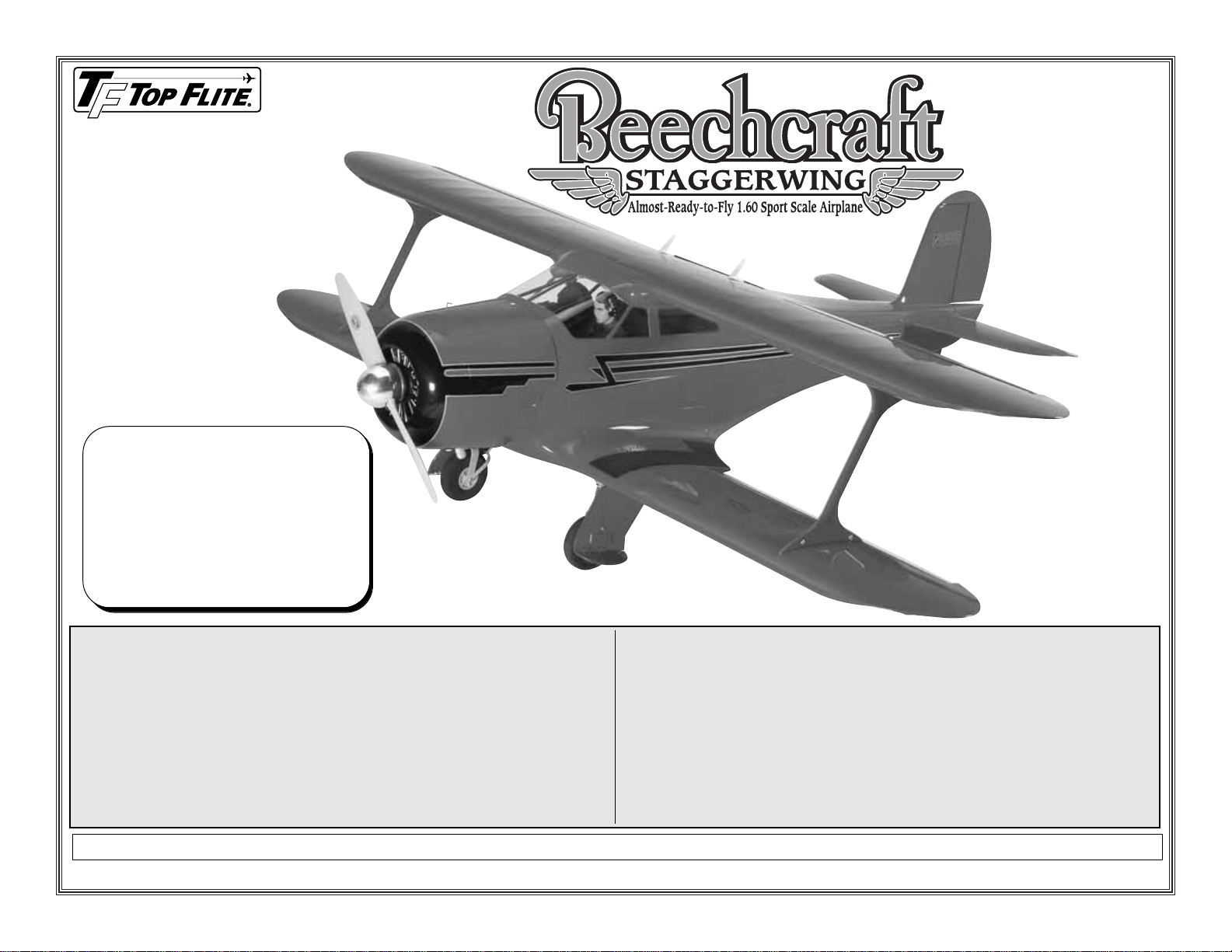
With its clean lines, negatively staggered wings, and
retractable landing gear, the natural aesthetic beauty
of the “Staggerwing” has made it an uncontested
classic airplane. Even today the Beechcraft Model 17
Staggerwing is comparable to modern private aircraft.
This classiest of classic airplanes transported military
generals and executives throughout the Second
World War and for years afterwards. Top Flite has
returned this vintage airplane to the modeling
community in the form of a “W orld Class”ARF that we
are sure will bring you hours of great fun.
For the latest technical updates or manual
corrections to the Staggerwing visit the Top Flite web
site at www.top-flite.com.Open the “Airplanes” link,
and then select the Staggerwing ARF. If there is new
technical information or changes to this model a
“tech notice” box will appear in the upper left corner
of the page.
AMA
We urge you to join the AMA (Academy of Model
Aeronautics) and a local R/C club. The AMA is the
governing body of model aviation and membership is
required to fly at AMA clubs.Though joining the AMA
provides many benefits, one of the primary reasons
to join is liability protection. Coverage is not limited to
flying at contests or on the club field. It even applies
to flying at public demonstrations and air shows.
Failure to comply with the Safety Code (excerpts
printed in the back of the manual) may endanger
insurance coverage. Additionally, training programs
and instructors are available at AMA club sites to help
you get started the right way. There are over 2,500
AMA chartered clubs across the countr y.Contact the
AMA at the address or toll-free phone number below:
Academy of Model Aeronautics
5151 East Memorial Drive
Muncie, IN 47302-9252
Tele.(800) 435-9262
Fax (765) 741-0057
Or via the Internet at:
www.modelaircraft.org
IMPORTANT!!!
Two of the most important things you can do to
preserve the radio-controlled aircraft hobby are to
avoid flying near full-scale aircraft and avoid flying
near or over groups of people.
IMAA
The Top Flite Staggerwing is an excellent sport-scale
model and is eligible to fly in IMAA events.The IMAA
(International Miniature Aircraft Association) is an
organization that promotes non-competitive flying of
giant-scale models. If you plan to attend an IMAA
event, obtain a copy of the IMAA Safety Code by
contacting the IMAA at the address or telephone
number below, or by logging on to their web site at:
IMAA
205 S. Hilldale Road
Salina, KS 67401
(913) 823-5569
www.fly-imaa.org/imaa/sanction.html.
- 2 -
Page 3
SCALE COMPETITION
Though the Top Flite Staggerwing is an ARF and
may not have the same level of detail as an “all-out”
scratch-built competition model, it is a scale model
nonetheless and is therefore eligible to compete in
the
Fun Scale
class in AMA competition (we receive
many favorable reports of Top Flite ARFs in scale
competition!).In Fun Scale, the “b uilder of the model”
rule does not apply. To receive the five points for
scale documentation, the only proof required that a
full-size aircraft of this type in this paint/markings
scheme did exist is a single sheet such as a kit box
cover from a plastic model, a photo, or a profile
painting, etc. If the photo is in black and white, other
written documentation of color must be provided.
Contact the AMA for a rule book with full details.
If you would like photos of full-size Staggerwings for
scale documentation, or if you would like to study the
photos to add more scale details, photo packs are
available from:
Bob’s Aircraft Documentation
3114 Y uk on A ve
Costa Mesa, CA 92626
Telephone: (714) 979-8058
Fax:(714) 979-7279
www.bobsairdoc.com
1.Your Staggerwing should not be considered a toy, but
rather a sophisticated, working model that functions very
much like a full-size airplane. Because of its
performance capabilities, the Staggerwing, if not
assembled and operated correctly, could possib ly cause
injury to yourself or spectators and damage to property.
2. You must assemble the model according to the
instructions. Do not alter or modify the model, as
doing so may result in an unsafe or unflyable model.
In a few cases the instructions may diff er slightly from
the photos.In those instances the written instructions
should be considered as correct.
3.You must take time to build straight,true and strong.
4.You must use an R/C radio system that is in firstclass condition, and a correctly sized engine and
components (fuel tank, wheels, etc.) throughout the
building process.
5. You must correctly install all R/C and other
components so that the model operates correctly on
the ground and in the air.
6. You must check the operation of the model before
every flight to insure that all equipment is operating and
that the model has remained structurally sound.Be sure
to check clevises or other connectors often and replace
them if they show any signs of wear or fatigue.
7. If you are not an experienced pilot or have not
flown this type of model before, we recommend that
you get the assistance of an experienced pilot in your
R/C club for your first flights.If you’re not a member
of a club, your local hobby shop has information
about clubs in your area whose membership
includes experienced pilots.
8. While this kit has been flight tested to exceed
normal use, if the plane will be used for extremely
high stress flying, such as racing, or if an engine
larger than one in the recommended range is used,
the modeler is responsible for taking steps to
reinforce the high stress points and/or substituting
hardware more suitable for the increased stress.
9.W ARNING:The cowl, landing gear covers and wing
struts included in this kit are made of fiberglass, the
fibers of which may cause eye, skin and respiratory
tract irritation. Never blow into a part to remove
fiberglass dust, as the dust will blow back into your
eyes.Always wear saf ety goggles, a particle mask and
rubber gloves when grinding, drilling and sanding
fiberglass parts. Vacuum the parts and the work area
thoroughly after working with fiberglass parts.
Remember: Take your time and follow the
instructions to end up with a well-built model that
is straight and true.
We, as the kit manuf acturer , pro vide you with a top
quality, thoroughly tested kit and instructions, but
ultimately the quality and flyability of your finished
model depends on how you build it; therefore, we
cannot in any way guarantee the performance of
your completed model, and no representations
are expressed or implied as to the performance or
safety of your completed model.
PRO TECT YOUR MODEL,
YOURSELF & OTHERS
FOLLO W THESE IMPORT ANT
SAFETY PRECAUTIONS
- 3 -
Page 4
DECISIONS YOU MUST MAKE
This is a partial list of items required to finish the
Staggerwing that may require planning or decision
making before starting to build. Order numbers are
provided in parentheses.
RADIO EQUIPMENT
❏ 6-channel w/7 servos (6- 50oz/in, 1- 30oz/in) or
(with retracts) 8/9-channel w/9 servos (6- 50oz/in,
2- 30oz/in, 1- 90oz/in)
❏ 2 - 6" [150mm] servo extension (HCAM2701 for
Futaba®)
❏ 2 - 12" [300mm] servo extension (HCAM2711
for Futaba)
❏ 2 - Y-harness (HCAM2751 for Futaba)
❏ 1000 mAh battery (minimum)
❏ 6 - 54 oz/in servos (2-tail, 2-flaps, 1-rudder,
1-elevator)
❏ 2 - 30 oz/in servos (1-throttle, 1-retracts)
ENGINE RECOMMENDATIONS
The recommended engine for the Staggerwing is an
O.S.®1.60 two-stroke or four-stroke.
❏ For the 2-stroke engine we used the Bisson
Pitts muffler.(BISG4116)
❏ The O.S.1.60 4-stroke engine can use the O.S.
Flex-pipe.(OSMG2672)
RETRACTS
If you choose to put retracts on your Staggerwing, we
used the following:
❏ Robart #530STAG Retracts (ROBQ0536)
❏ Robart #188VR Air Control Kit Standard with VR
Valve (ROBQ2302)
❏ Robart #169 Pressure Tubing (ROBQ2369)
❏ Robart #121 Scale Retract Tail Wheel (ROBQ2210)
❏ 90 oz-in Servo (such as the Futaba S3305,
FUTM0035 for the tail wheel)
ADDITIONAL ITEMS REQUIRED
ADHESIVES & BUILDING SUPPLIES
This is the list of Adhesives and Building Supplies
that are required to finish the Staggerwing.
❏ 1/2 oz. [15g] Thin Pro™CA (GPMR6001)
❏ 1 oz. [30g] Medium Pro CA+ (GPMR6008)
❏ Pro 30-Minute Epoxy (GPMR6047)
❏ Pro 6-Minute Epoxy (GPMR6045)
❏ R/C Foam Rubber (1/4" [6mm] - HCAQ1000
❏ 3' [900mm] Standard Silicone Fuel
Tubing (GPMQ4131)
❏ Drill Bits: 1/16" [1.6mm], 5/64" [2mm], 3/32"
[2.4mm], 7/64" [2.8mm], 1/8" [3.2mm], 9/64"
[3.6mm], 5/32" [4mm], 3/16" [4.8mm]
❏ 4-40 Tap and Dr ill Set (GPMR8101)
❏ 8-32 Tap and Dr ill Set (GPMR8103)
❏ Small T-Pins (100, HCAR5100)
❏ #1 Hobby Knife (HCAR0105)
❏ #11 Blades (5-pack, HCAR0211)
❏ Stick-On Segmented Lead Weights (GPMQ4485)
❏ Silver Solder w/Flux (GPMR8070)
❏ 21STCentury®Sealing Iron (COVR2700)
❏ 4 oz. [113g] Aerosol CA Activator (GPMR634)
❏ CA Applicator Tips (HCAR3780)
❏ Epoxy Brushes (6, GPMR8060)
❏ Mixing Sticks (50, GPMR8055)
❏ Mixing Cups (GPMR8056)
❏ Microballoons (TOPR1090)
❏ Threadlocker Thread Loc king Cement (GPMR6060)
OPTIONAL SUPPLIES & TOOLS
Here is a list of optional tools mentioned in the
manual that will help you build the Staggerwing.
❏ Hobbico®Duster™Compressed Air (HCAR5500)
❏ Masking Tape (TOPR8018)
❏ Denatured Alcohol (for epoxy clean up)
❏ Panel Line Pen (TOPQ2510)
❏ Rotary Tool (such as Dremel)
❏ Rotary Tool Reinforced Cut-Off Wheel (GPMR8020)
❏ Servo Horn Dr ill (HCAR0698)
❏ Hobby Heat
™
Micro Torch (HCAR0750)
❏ AccuThrow™Deflection Gauge (GPMR2405)
❏ Precision Magnetic Prop Balancer (TOPQ5700)
❏ CG Machine™(GPMR2400)
❏ Dead Center™Engine Mount Hole
Locator (GPMR8130)
IMPORTANT BUILDING NOTES
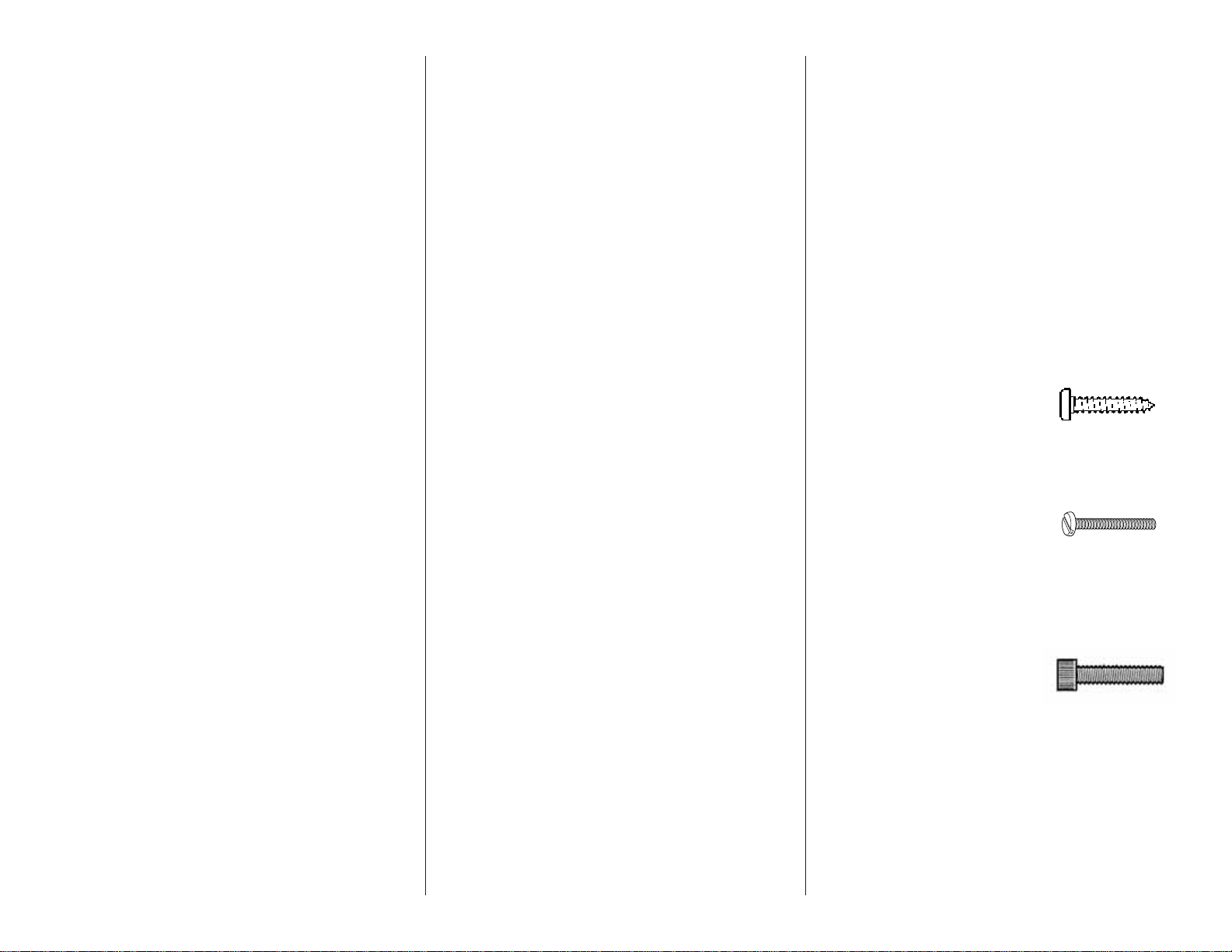
• There are two types of screws used in this kit:
Sheet metal screws are designated by a number
and a length. For example #6 x 3/4" [19mm]
This is a number six screw that is
3/4" [19mm] long.
Machine screws are designated by a number, threads
per inch, and a length.For example 4-40 x 3/4" [19mm]
This is a number four screw that
is 3/4" [19mm] long with forty
threads per inch.
Socket head cap screws are designated by a
number, threads per inch and a length. For example
4-40 x 3/4" [19mm]
This is a number four screw that
is 3/4" [19mm] long with forty
threads per inch
.
• When you see the term “test fit” in the instructions, it
means that you should first position the part on the
assembly without using any glue, then slightly modify
or custom fit the part as necessar y for the best fit.
•Whenever the term “glue” is wr itten, you should rely
upon your experience to decide what type of glue to
use. When a specific type of adhesive works best for
that step, the instructions will make a recommendation.
- 4 -
Page 5

• Whenever just epoxy is specified, you may use
either 30-minute (or 45-minute) epoxy or 6-minute
epoxy. When 30-minute epoxy is specified, it is
highly recommended that you use only 30-minute
(or 45-minute) epoxy, because you will need the
working time and/or the additional strength.
• Photos and sketches are placed before the step they
refer to .Frequently you can study photos in follo wing
steps to get another view of the same parts.
• The Staggerwing is factory-covered with Dark Red
Top Flite MonoKote®film (TOPQ0218 for a six foot
roll).Should repairs ever be required, MonoKote can
be patched with additional MonoKote purchased
separately. MonoKote is packaged in six-foot rolls,
but some hobby shops also sell it by the foot.If only
a small piece of MonoKote is needed for a minor
patch, perhaps a fellow modeler would give you
some. MonoKote is applied with a model airplane
covering iron, but in an emergency a regular iron
could be used. A roll of MonoKote includes full
instructions for application.
METRIC CONVERSIONS
To conv ert inches to millimeters, multiply inches by 25.4
ORDERING REPLACEMENT PARTS
Replacement parts for the Top Flite Staggerwing are
available using the order numbers in the
Replacement Parts List that follows. The fastest,
most economical service can be provided by your
hobby dealer or mail-order company.
To locate a hobby dealer, visit the Hobbico web site
at www.hobbico.com. Choose “Where to Buy” at the
bottom of the menu on the left side of the page.
Follow the instructions provided on the page to
locate a U.S., Canadian or International dealer.
Parts may also be ordered directly from Hobby
Services by calling (217) 398-0007, or via facsimile
at (217) 398-7721, but full retail prices and shipping
and handling charges will apply. Illinois and Nevada
residents will also be charged sales tax. If ordering
via fax, include a Visa®or MasterCard®number and
expiration date for payment.
Mail parts orders and payments by personal check to:
Hobby Services
3002 N Apollo Drive, Suite 1
Champaign IL 61822
Be certain to specify the order number exactly as
listed in the Replacement Parts List. Payment by
credit card or personal check only; no C.O.D.
If additional assistance is required for any reason
contact Product Support at:
(217) 398-8970
productsupport@greatplanes.com
REPLACEMENT PARTS LIST
Description How to purchase
Missing pieces Contact Product Support
Instruction manual Contact Product Support
Full-size plans Not available
Order # Description
TOPA1680 ........T op Wing w/Joiner
TOPA1681 ........Bottom Wing
TOPA1682 ........Fuselage
TOPA1683 ........Rudder w/Hinges
TOPA1684 ........Horizontal Stabilizer
TOPA1685 ........Landing Gear w/Tailwheel
TOPA1686 ........Gear Doors & Wheel Covers
w/Actuating Wires
TOPA1687 ........Cowl
TOPA1688 ........Cockpit Floor w/ Seat Backs
TOPA1689 ........Tail Cone
TOPA1690 ........Horizontal Stabilizer Tubes
TOPA1691 ........Interplane Wing Strut Mounts
TOPA1692 ........Interplane Wing Strut
TOPA1693 ........Wing Mounting Blades
.4mm = 1/64"
.8mm = 1/32"
1.6mm = 1/16"
2.4mm = 3/32"
3.2mm = 1/8"
4mm = 5/32"
4.8mm = 3/16"
6.4mm = 1/4"
9.5mm = 3/8"
12.7mm = 1/2"
15.9mm = 5/8"
19mm = 3/4"
25.4mm = 1"
50.8mm = 2"
76.2mm = 3"
152.4mm = 6"
304.8mm = 12"
381mm = 15"
457.2mm = 18"
533.4mm = 21"
609.6mm = 24"
762mm = 30"
914.4mm = 36"
- 5 -
Page 6
- 6 -
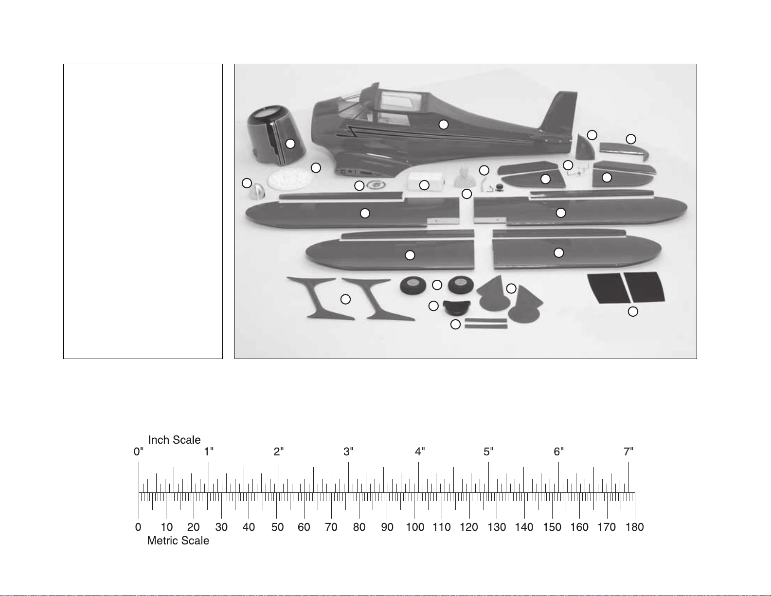
KIT CONTENTS
1. Fuselage
2. Cowl
3. Tail Cone
4. Rudder
5. Stab with Elevators
6. Elevator Control Wire
7. Tail Wheel Hardware
8. Pilot
9. Fuel Tank
10. Pull-Pull Wire with Hardware
11. Spinner
12. Top Right Wing with Aileron
13. Top Left Wing with Aileron
14. Bottom Right Wing with Flap
15. Bottom Left Wing with Flap
16. Struts
17. Main Wheels
18. Seat Backs
19. T ail Wheel Doors
20. Landing Gear Doors
21. Cockpit Floor
22. Dummy Engine
To convert inches to millimeters, multiply inches by 25.4
1
2
22
11
10
12
16
9
14
17
18
19
7
5
8
13
15
20
3
6
4
5
21
Page 7
- 7 -
PREPARATIONS
❏ 1. If you have not done so already, remove the
major parts of the kit from the box and inspect for
damage.If any parts are damaged or missing, contact
Product Support at the address or telephone number
listed in the “Kit Contents” section on page 6.
❏ 2.Remove the tape and separate the ailerons and
flaps from the wing and the elevators from the stab.
Use a covering iron with a covering soc k on high heat
to tighten the covering if necessary. Apply pressure
over sheeted areas to thoroughly bond the covering
to the wood.
BUILD THE WING
Install the Flaps/Ailerons
Do the bottom right wing first so your work
matches the photos the first time through.
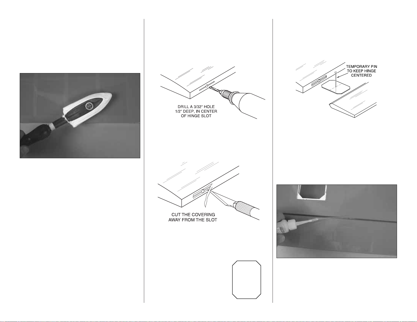
❏❏❏❏1.Drill a 3/32" [2mm] hole, 1/2" [13mm] deep
in the center of each hinge slot to allow the CA to “wick”
in. Follow-up with a #11 blade to clean out the slots.
Hint: If you have one, use a high-speed rotary tool to
drill the holes.
❏❏❏❏2. Use a shar p #11 blade to cut a strip of
covering from the hinge slots in the wing and aileron.
❏❏❏❏3. Cut sixteen 1" x 1"
[25mm x 25mm] hinges from a
CA hinge strip. Snip off the
corners so they go in easier.
Note:The following steps ref er to the installation of the
flaps/ailerons. The bottom wing of the Staggerwing
has flaps.The top wing has ailerons. If you look at the
location of the hinge slots of each you will see the
flaps are hinged off the centerline of the flap and the
aileron is hinged on the centerline.
❏❏❏❏4. Test fit the flap/aileron to the wing with
the hinges. If the hinges don’t remain centered, stick a
pin through the middle of the hinge to hold it in position.
❏❏❏❏5.Remove any pins y ou ma y hav e inserted
into the hinges. Adjust the flap / aileron so there is a
small gap between the LE of the aileron and the wing.
The gap should be small, just enough to see light
through or to slip a piece of paper through.
❏❏❏❏6.Apply six drops of thin CA to the top and
bottom of each hinge. Do not use CA accelerator.
After the CA has fully hardened, test the hinges by
pulling on the aileron.
❏ 7. Repeat steps 1- 6 for the left wing panel and the
two wing panels for the top wing.
Page 8
Install the Aileron Servos and Pushrods
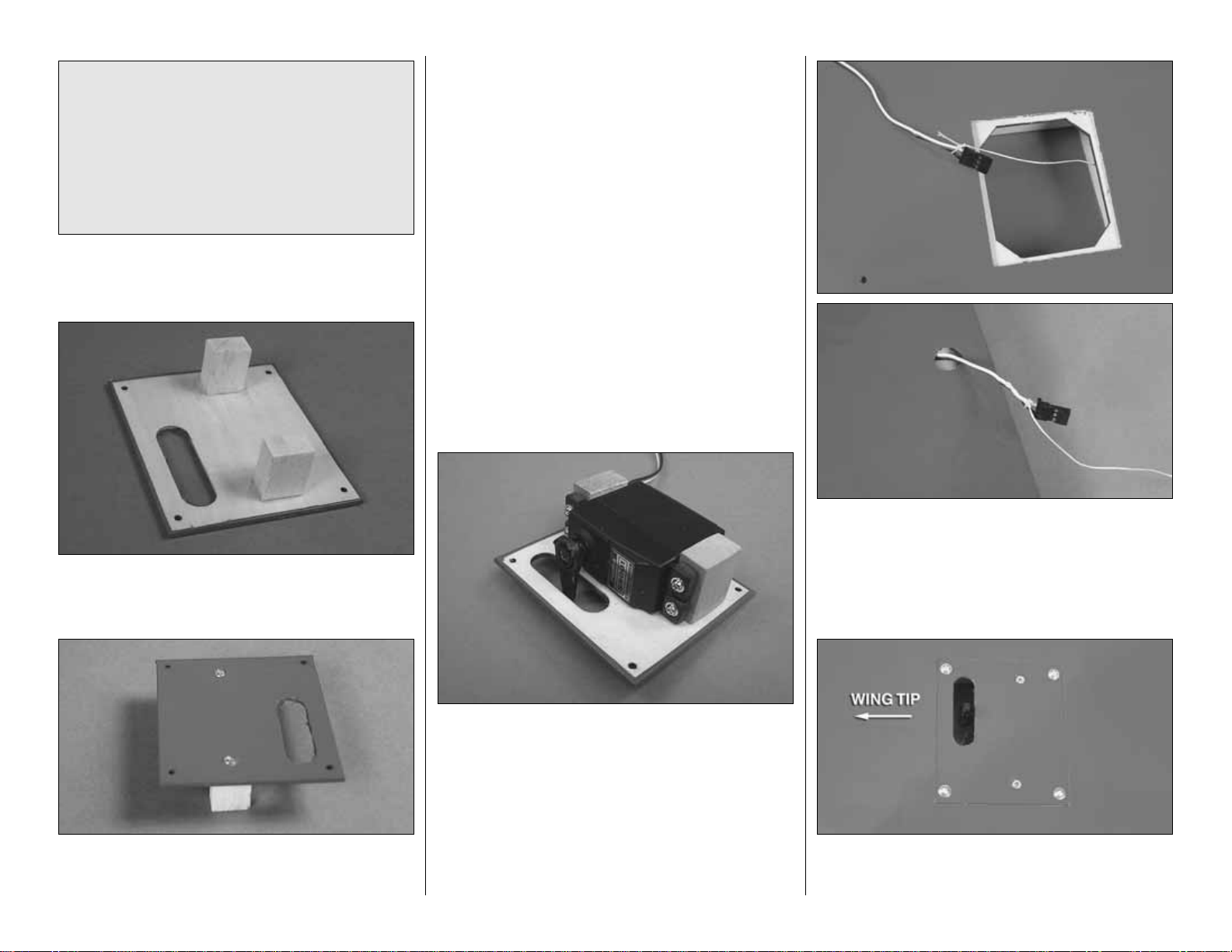
❏❏1. Glue two 5/16" x 1/2" x 11/16" [8mm x 13mm x
18mm] hardwood blocks to the servo cover. Position
the blocks so the servo fits between the blocks.
❏❏2. Drill a 1/16" [1.6mm] hole through the ser vo
cover into the center of the servo mounting blocks.
Install and then remove a #2 x 3/8" [10mm] wood
screw into the holes you drilled. Apply a drop of thin
CA into the holes to harden the threads.Once the glue
has cured, install the screws into the servo cover.
❏❏3. Install a 12" [305mm] ser vo extension onto
the servo lead. Secure the extension to the lead with
tape, a piece of shrink tube or some other method to
keep them from coming unplugged.
❏❏4. Place the servo onto the servo mounting
blocks.Drill through the servo mounting holes with a
1/16" [1.6mm] drill bit. Remove the servo from the
servo cover. Install and then remove a servo
mounting screw into each of the holes you have
drilled. Apply a drop of thin CA into the holes to
harden the threads. Once the glue has cured, install
the servo onto the servo cover using the hardware
included with your servo. Center the servo and then
install a servo arm as shown.
❏❏5. Inside the servo bay a string is taped.Tie the
string to the servo extension. Pull the string and the
servo lead through the wing.Untie the string from the
lead and insert the lead through the small hole on the
top of the wing at the root.Tape the lead to the wing
to prevent it from falling back into the wing.
❏❏6. Place the servo cover onto the wing. The
opening for the servo arm should be pointed
towards the wingtip. Drill a 1/16" [1.6mm] hole
Did you know…
At the height of the Great
Depression, aircraft executive Walter H. Beech
and airplane designer T.A. “T ed”Wells joined forces
to collaborate on a project many considered
foolhardy—a large, powerful, and fast biplane built
specifically for the business executive. The Beech
Model 17, popularly known as the “Staggerwing,”
was first flown on November 4, 1932.
- 8 -
Page 9
through each corner of the cover.Remove the cover.
Then, install and remove a #2 x 3/8" [10mm] screw
into the holes you drilled. Apply a drop of thin CA into
the holes to harden the threads. Once the glue has
hardened, mount the servo cover with #2 x 3/8"
[10mm] screws and #2 flat washers.
❏❏7.Place a nylon control horn in line with the outer
hole in the servo arm. When positioned properly the
control horn will rest on a hardwood plate in the aileron.
Mark the location of the mounting holes onto the
aileron.Drill a 1/16" [1.6mm] hole on the marks, drilling
through the plywood plate
but not
through the top of
the aileron. Insert and remove a #2 x 3/8” [10mm]
screw into each of the holes. Apply a couple drops of
thin CA into the holes to harden the threads. Once the
glue has hardened attach the horn to the aileron with
two #2 x 3/8" [10mm] screws.
❏❏8. Screw a nylon clevis onto a .074 x 6" [152mm]
threaded wire 20 turns.Slide a nylon clevis retainer onto
the clevis.Install the clevis into the second hole from the
end of the control horn.Then, slide the silicone retainer
over the cle vis. Drill a 5/64 [2mm] hole in the outer hole
of the servo arm. Center the servo and the aileron.With
a fine tip marker, mark the wire where it aligns with the
outer hole of the servo arm. Make a 90 degree bend on
the mark. Cut the wire so the wire is 3/8” [10mm] in
length after the bend.Insert the wire into the servo arm
and lock it in place with a nylon Faslink.
❏ 9. Repeat steps 1-8 for the left wing panel.
Install the Flap Servos and Pushrods
❏❏1. Glue two 5/16" x 1/2" x 11/16" [8mm x 13mm x
18mm] hardwood blocks to the servo cover. Position
the blocks so the servo fits between the blocks.
❏❏2. Drill a 1/16" [1.6mm] hole through the ser vo
cover into the center of the servo mounting blocks.
Install and then remove a #2 x 3/8" [10mm] wood
screw into the holes you drilled. Apply a drop of thin
CA into the holes to harden the threads.Once the glue
has cured, install the screws into the servo cover.
❏❏3.Install a 6" [152mm] servo extension onto the
servo lead. Secure the extension to the lead with
tape, a piece of shrink tube or some other method to
keep them from coming unplugged.
❏❏4. Place the servo onto the servo mounting
blocks.Drill through the servo mounting holes with a
1/16" [1.6mm] drill bit. Remove the servo from the
servo cover. Install and then remove a servo
mounting screw into each of the holes you have
drilled. Apply a drop of thin CA into the holes to
harden the threads. Once the glue has cured, install
the servo onto the servo cover using the hardware
included with your servo. Center the servo and then
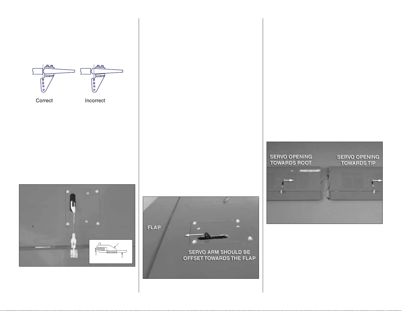
offset the servo arm as shown.
❏❏5. Inside the servo bay a string is taped.Tie the
string to the servo extension. Pull the string and the
servo lead through the wing.Untie the string from the
lead and insert the lead through the small hole on the
top of the wing at the root.Tape the lead to the wing
to prevent it from falling back into the wing.
❏❏6. Place the servo cover onto the wing. The
opening for the servo arm should be pointed
towards the wing root on the right wing. (When
installing the left wing the opening will be towards the
wing tip). Drill a 1/16" [1.6mm] hole through each
corner of the cover. Remove the cover. Then, install
and remove a #2 x 3/8" [10mm] screw into the holes
you drilled. Apply a drop of thin CA into the holes to
harden the threads. Once the glue has hardened,
mount the servo cover with #2 x 3/8" [10mm] screws
and #2 flat washers.
- 9 -
FASLINK
HORN
2-56 (.074")
PUSHROD WIRE
SERVO
Page 10
❏❏7. Place a nylon control horn backwards from
what would be considered the normal mounting
position, in line with the outer hole in the servo arm.
When positioned properly the control horn will rest
on a hardwood plate in the flap.Mark the location of
the mounting holes onto the flap. Drill a 1/16"
[1.6mm] hole on the marks, drilling through the
plywood plate
but not
through the top of the flap.
Insert and remove a #2 x 3/8" [10mm] screw into
each of the holes. Apply a couple drops of thin CA
into the holes to harden the threads. Once the glue
has hardened, attach the horn to the aileron with two
#2 x 3/8" [10mm] screws.
❏❏8. Screw a nylon clevis onto a .074 x 6” [152mm]
threaded wire 20 turns.Slide a nylon clevis retainer onto
the clevis.Install the clevis into the second hole from the
end of the control horn.Then, slide the silicone retainer
over the cle vis.Drill a 5/64" [2mm] hole in the outer hole
of the servo arm. Center the servo and the flap.With a
fine tip marker, mark the wire where it aligns with the
outer hole of the servo arm. Make a 90 degree bend on
the mark. Cut the wire so the wire is 3/8" [10mm] in
length after the bend.Insert the wire into the servo arm
and lock it in place with a nylon Faslink.
❏ 9. Repeat steps 1-8 for the left wing panel.
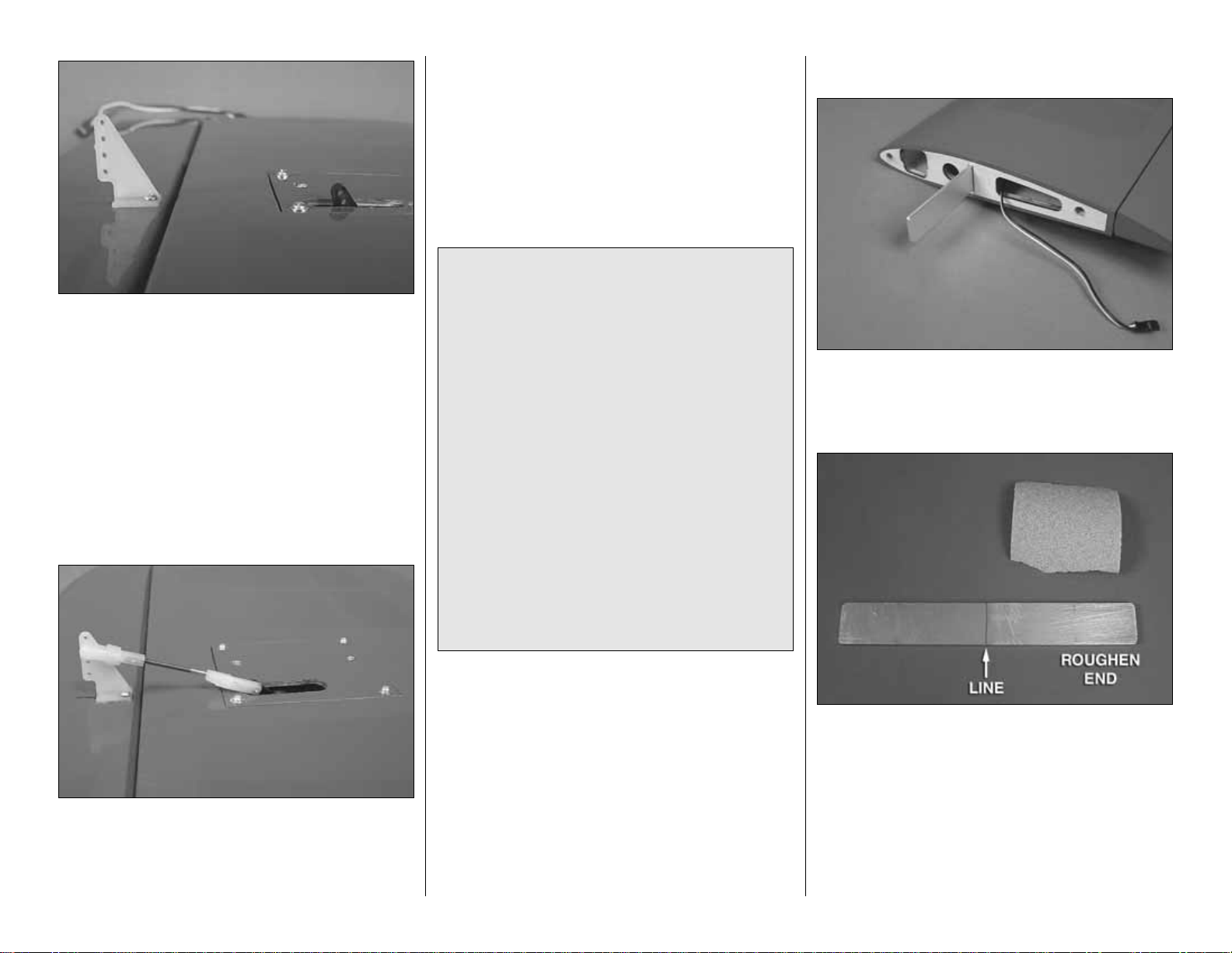
Install the Wing Joiners
❏❏
1. Locate three aluminum wing joiners. Slide
one joiner completely into the joiner pocket of the
lower right wing. The lower wing is the shorter wing
panel with the flaps.
❏❏2.Draw a line on the joiner where it extends out of
the joiner pocket.Roughen the portion of the joiner that
extends into the joiner pocket with 80-grit sandpaper.
❏❏3. Apply 30-minute epoxy to the inside of the
joiner pocket and the roughened end of the
aluminum joiner. Insert the joiner into the joiner
pocket. Be sure to insert the joiner fully into the
pocket.Clean any excess epoxy away from the wing
and joiner with rubbing alcohol.
Did you know…
The Model 17s could achieve
a top speed of 201 miles per hour (323 kilometers
per hour), which made it faster than most military
aircraft of the era.Staggerwing’s speed also made
it the darling of the air racers of the 1930s.An early
version of Model 17 won the 1933 T exaco T r ophy
Race. In 1935, a British diplomat, Capt. H.L.
Farquhar, successfully flew around the world in a
Model B17R, traveling 21,332 miles (34,331
kilometers) from New York to London, by way of
Siberia, Southeast Asia, the Middle East, North
Africa and back across Europe. Aviatrices Louise
Thaden and Blanche Noyes won the 1936
Bendix Trophy Race in a Model C17R
Staggerwing.Thaden also won the Harmon Troph y
for her achievement. Aviatrix Jackie Cochran set
a women’s speed record of 203.9 mph,
established an altitude record of over 30,000 feet
(9.144 meters), and finished third in the 1937
Bendix Trophy Race, all while flying a special
Model D17W Staggerwing.
- 10 -
Page 11
- 11 -
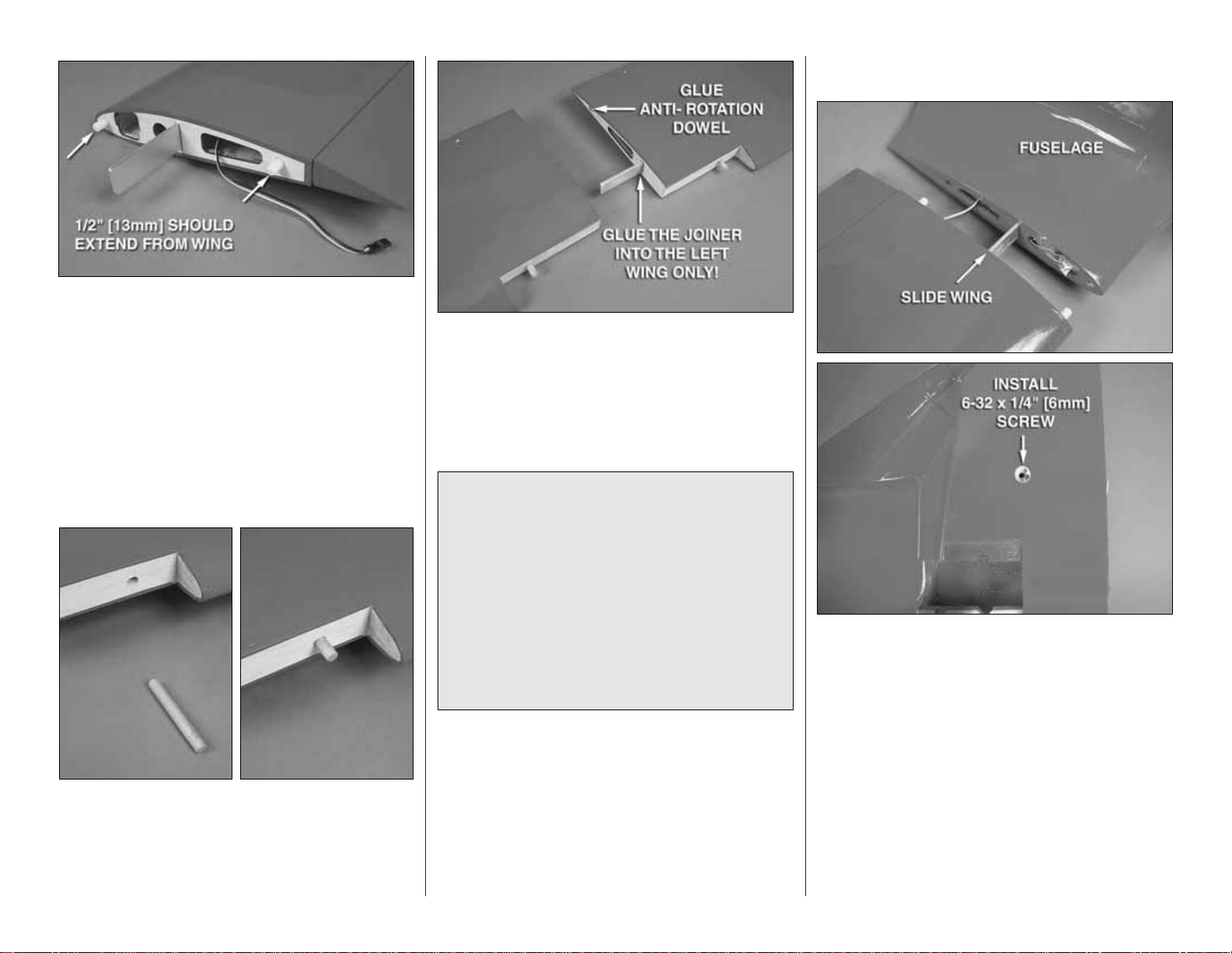
❏❏4. Using 30-minute epoxy, glue two nylon anti-
rotation dowels into the holes at the root of the wing.
Glue them in so 1/2" of the dowels extends from
the wing.
❏ 5. Repeat steps 1-4 for the other wing.
❏ 6. Test fit a 3/8" x 2-1/2" [10mm x 64mm] wood
dowel into the hole at the leading edge of the top
wing. Push it into the wing, making sure it catches in
the hole further inside of the wing. Once you are
satisfied with the fit, epoxy them in place.Repeat this
for the other wing panel.
❏ 7. Glue the remaining wing joiner into the joiner
pocket of the top left wing using the same procedure
used for installing them in the bottom wing.
Only glue
the joiner into the left wing!
Glue the remaining
nylon anti-rotation dowel in the hole in the wing root.
Attach the Wings to the Fuselage
❏ 1. Slide the bottom wing panels into the sides of
the fuselage.Install a 6-32 x 1/4" [6mm] socket head
cap screw into the threaded holes on the bottom of
the fuselage. Push the wing tight to the fuselage.
Then, tighten the screw against the wing joiner.
Did you know…
The Model 17’s unusual wing
configuration—the upper wing inversely staggered
behind the lower—and unique shape resulted in a
design that maximized the pilot’s visibility while
minimizing the aircraft’s tendency to stall.The fabriccovered fuselage was faired with wood formers and
stringers. The Staggerwing’s use of retractable
conventional landing gear, uncommon at that time,
combined with streamlining, reducing the weight of
the materials, and its use of powerful radial engines
ranging from 225 to 710 horsepower produced an
aircraft with impressive performance.
Page 12
❏ 2. Slide the two top wings together.On the bottom
of the right wing you will see a threaded hole. Install
a 6-32 socket head cap screw into the hole. Make
sure the wings are tight against each other and then
tighten the screw against the wing joiner.
❏ 3. Install the top wing onto the top of the fuselage.
Secure the wing to the fuselage with two
1/4-20 x 2" [50mm] nylon wing bolts.
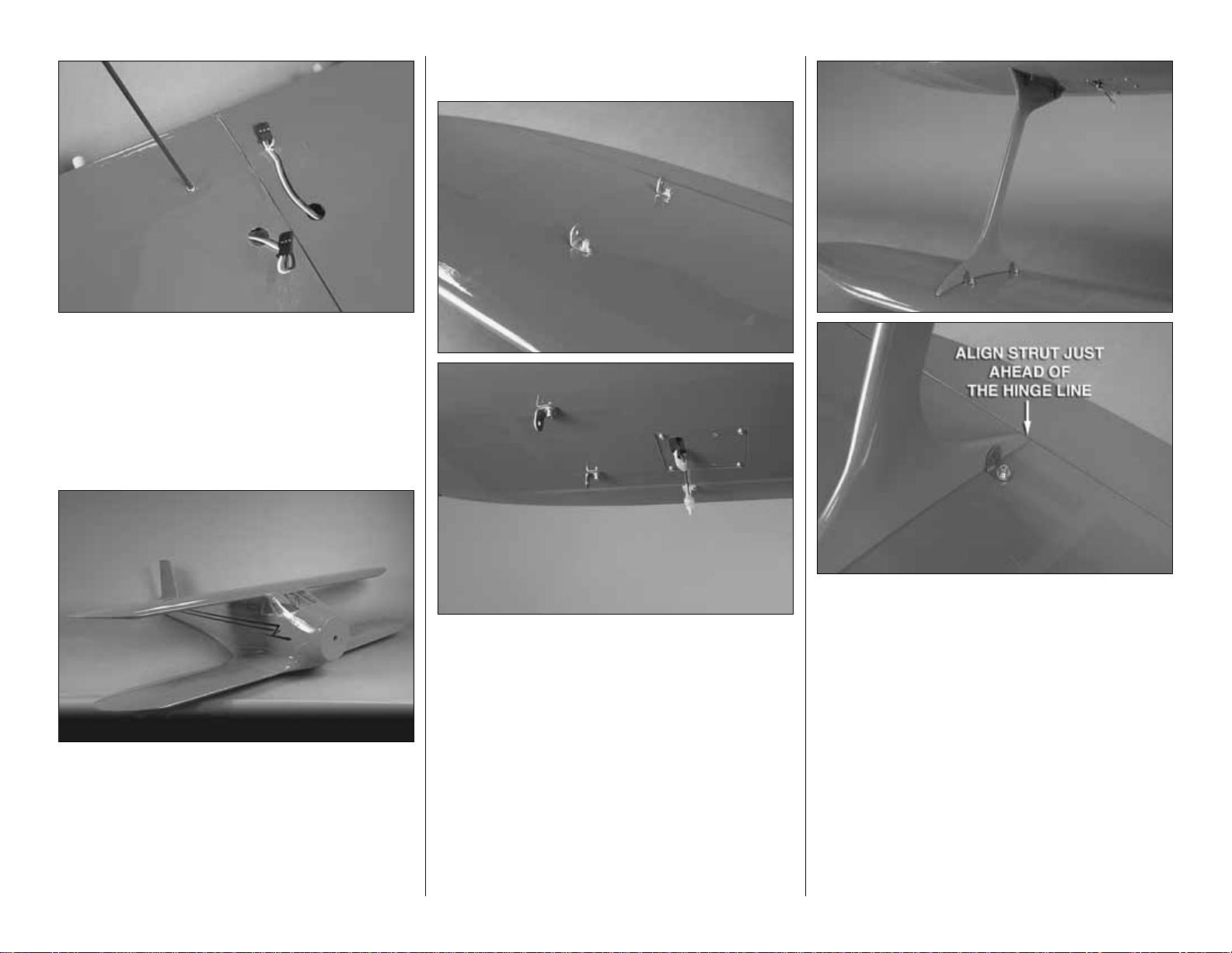
Install the Struts
❏ 1. On the top of the bottom wing and the bottom of
the top wing locate the pinholes that the manufacturer
made in the MonoKote film. Cut the covering on the
pinholes to reveal the 4-40 blind nuts pre-installed in
the wing. Install a metal bracket in each of the holes
with a 4-40 x 1/2" [13mm] socket head cap screw,
#4 flat washer and #4 lock washer .Do this for both the
left and right wings.
❏ 2. Slide the struts in place for both the left and right
wings.When positioning them the trailing edge of the
strut should be just in front of the hinge line for the flap.
❏ 3. When you are satisfied with the positioning of
the struts, mark the location of the holes from the
bracket onto the strut. Drill a pilot hole through the
marks with a 1/16" [1.6mm] drill. Then, drill through
the pilot hole with a 1/8" [3mm] bit.
- 12 -
Page 13
❏ 4. Mount the strut to the bracket with a 4-40 x 1/2"
[13mm] Philips head screw, flat washer and 4-40
nylon lock nut. Do this for all four holes. Repeat this
for the other wing.
❏ 5. Remove the wings before moving on to the
next section.
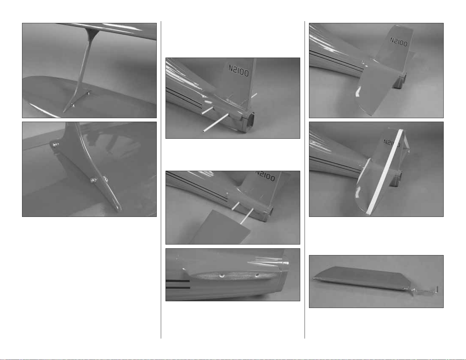
BUILD THE FUSELAGE
Install the Stabilizers, Elevators
and Rudder
❏ 1. Slide the two aluminum stab tubes into the
back of the fuselage. The longer of the tubes goes
into the rear-most hole.
❏ 2. Slide the stabs onto the tubes, making sure that
they slide on and fit tight to the fuselage.When you
are satisfied with the fit, remove the stabs. Then
roughen the fuselage with 80-grit sandpaper where
the stab meets with the fuselage.
❏ 3. Apply epoxy to the root of each stab and the
fuselage side you roughed up.Slide the stabs onto the
aluminum tubes, pressing them firmly against the stab.
Hold the stabs tight to the fuselage with masking tape.
❏ 4. Test fit the joiner and the right elevator to the
stab, making sure that the elevator control arm is
inside of the fuselage. Epoxy the wing joiner to the
right elevator.
- 13 -
Page 14
❏ 5. Cut nine 1" x 1" [25mm x 25mm] hinges from a
CA hinge strip. Insert three hinges into the elevator.
If the hinges don’t remain centered, stick a pin
through the middle of the hinge to hold it in position.
Slide the hinges into the elevator
❏ 6. Remove any pins you may have inserted into
the hinges.Adjust the elevator so there is a small gap
between the LE of the elevator and the stab.The gap
should be small, just enough to see light through or
to slip a piece of paper through. Apply six drops of
thin CA to the top and bottom of each hinge. Do not
use CA accelerator.After the CA has fully hardened,
test the hinges by pulling on the elevator.
❏ 7.Install three hinges into the left elevator.Test fit the
elevator to the stab, making sure you fit the elevator
joiner into the hole in the leading edge of the elevator.
Once you are satisfied with the fit, apply epoxy into the
hole in the leading edge of the left elevator and then
slide the hinges into the stab. Secure the hinges with
thin CA the same as was done with the right elevator.
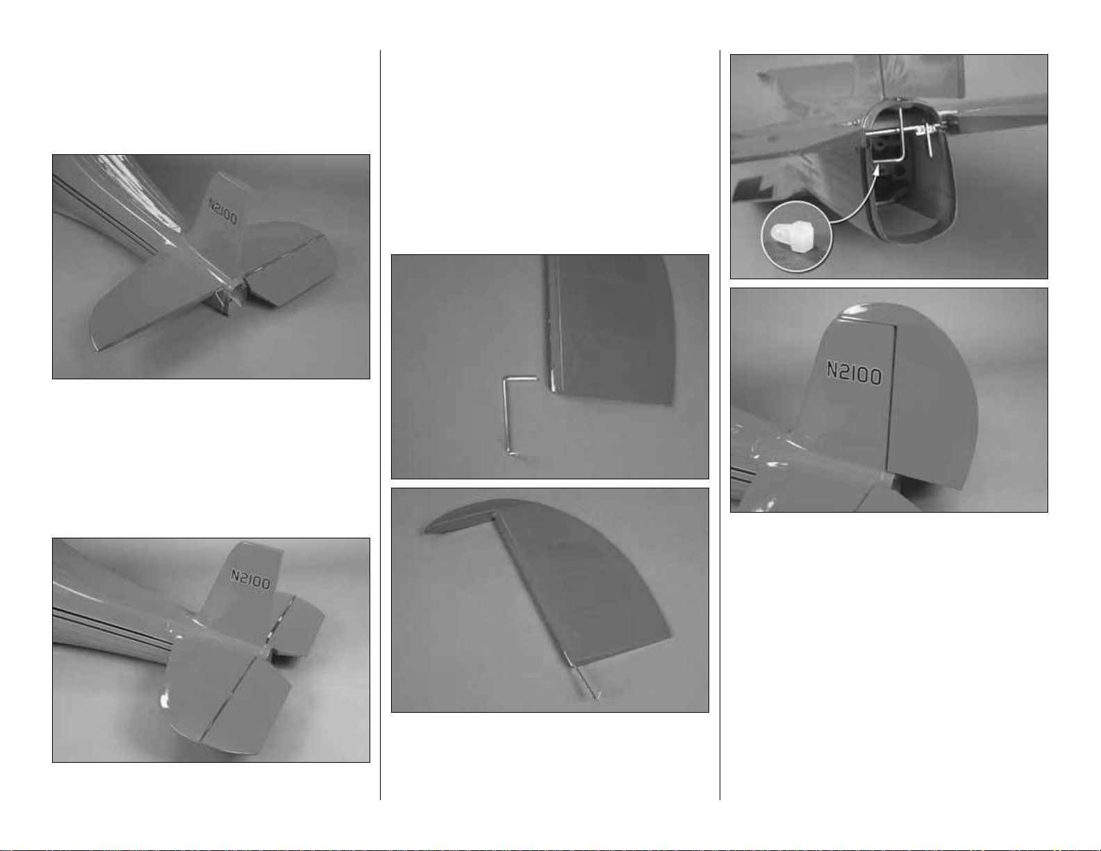
❏ 8. Glue the rudder control horn into the rudder
with epoxy.When gluing it into the rudder be sure to
glue the end of the wire
without the threads
into the
rudder. Allow the glue to completely harden before
moving on to the next step.
❏ 9. Install three hinges into the rudder the same as
was done with the elev ator .Insert the end of the rudder
control horn into the hole in the top of the fuselage.
Thread the nylon clevis link onto the threaded end of
the rudder control wire. Guide the hinges into the
vertical fin.Once satisfied with the fit, apply six drops of
thin CA to the top and bottom of each hinge.
- 14 -
Page 15

INSTALL THE LANDING GEAR
The following instructions are for the installation of the
fixed landing gear .If you will be installing the retractable
landing gear skip ahead to the instructions for the
retractable landing gear. Should you later decide to
change over to the retractable landing gear, the
mounting holes match so the gear is interchangeable.
Fixed Landing Gear
❏❏
1. Locate the components of the landing gear
blocks.Assemble them as shown using eight #4 x 3/8"
[10mm] screws on each landing gear block.
❏❏2. Place the assembly into the opening in the
fuselage
. Note that the hole for the landing gear wire
should be towards the inside of the fuselage.
Drill a
5/32" [4mm] hole through each of the mounting holes
and into the landing gear rails.Mount the block to the
landing gear rails with four #6 x 1/2" [13mm] screws
and a #6 lock washer.
❏❏3.T est fit the landing gear wire into the hole in the
landing gear block.When positioned properly the wire
should fit into the slot. If the wire does not fully seat,
grind away some of the nylon with a Dremel tool to
allow the radius of the wire to fully seat into the block.
❏❏4. Insert the landing gear wire into the landing
gear block. Using #2 x 3/8" [910mm] screws, attach
two nylon landing gear straps to the landing gear
block as shown.
❏❏5. Mark a line parallel to the mold line at the
bottom of the landing gear door. Mark the line 1/8"
[3mm] from the mold line. Cut on the line you have
drawn with a razor saw.
❏❏6. Measure 3/4" [19mm] from the mold line
and draw a line. Roughen the area shown with 80
grit sandpaper.
- 15 -
Page 16

- 16 -
❏❏7. Locate the landing gear door wood mounting
bracket. Place it on the landing gear wire as shown.
Drill a 1/16" [1.6mm] hole for each of the landing gear
strap mounting holes. Install three flat nylon landing
gear straps with #2 x 3/8" [10mm] sheet metal screws.
❏❏8. Apply 6-minute epoxy to the part of the door
that you roughened up.Place the door onto the wood
mounting bracket, positioning the door so the axle is
in the center of the door and the bottom of the door is
approximately 3/4" from the bottom of the fuselage.
Hold the door in position while the glue hardens.
❏❏9. File a flat spot on the end of the axle. Install
a 5mm wheel collar and set screw onto the axle.
❏❏10. Slide a wheel onto the axle followed by the
wheel collar. Tighten the set screw against the flat
spot you made.Open the lower portion of the landing
gear door as shown. Apply a couple of drops of thin
CA to the hinge to keep the door fixed in place.
Note: Read step 11 and 12 before proceeding with
them. The installation of a cover to close the wheel
well is optional.The door will reduce the overall drag
but is not required for good flight performance.
❏❏11. From the 1/4" x 1/4" x 12" [6mm x 6mm x
300mm] balsa stick, cut pieces 3/4" [19mm] in length.
Glue them in the wheel well 1/16" [1.6mm] below the
bottom of the fuselage.
❏❏12. Glue the plywood wheel cover to the balsa
blocks and the fuselage.
❏ 13. Repeat steps 1-12 for the left landing gear.
Page 17

Fixed T ail Wheel
❏ 1. Using the hardware in the tail wheel bag, assemble
the tail wheel components as shown. Be sure to apply
thread locker to the set screws during assembly.
❏ 2. Insert the tail wheel mounting bracket into the
fuselage, aligning the holes in the mounting bracket
with the holes in the wood mounting plate inside of the
fuselage. Mount the tail wheel to the wood mounting
plate with two 4-40 x 1/2" [13mm] socket head cap
screws, #4 flat washers and #4 lock washers.
Tail Wheel Door Installation (Fixed)
The following steps cov er the installation of the tail wheel
doors. This is optional and not required for flight
performance. If you fly from a grass field that is very
rough or has long grass, you might wish to omit the
installation of the doors due to the amount of clearance
between the doors and the ground.If you omit the doors
you might also consider replacing the 1-1/4" [32mm] tail
wheel with the 2" [51mm] wheel included in this kit.
❏❏1. Locate the fiberglass tail wheel doors and
four pinned hinges. Place the doors into the opening
aligning the simulated stringers on the fuselage with
the doors to determine which door is the right and left.
❏❏2. On the backside of the door make a mark
1/2" [13mm] in from each end of the door.
❏❏3.Place the hinges on the line and make another
mark at the other end of the hinge to mark the exact
placement of the hinge. Do this for both hinges.
❏❏4. Measure in from the side of the door 1/16"
[1.6mm] and draw a line as shown.
- 17 -
Page 18

❏❏5. Make a file by cutting a piece of plywood the
width of the hinge. Apply 180-grit sandpaper to the
plywood. Sand the door to make a 1/16" [1.6mm]
groove in the door at the location of each hinge.
❏❏6.Roughen the fiberglass with sandpaper in the
area the hinges will be glued to the doors. After
sanding, clean the area with rubbing alcohol.
❏❏7. Apply a couple of drops of lightweight oil to
the hinge pin to prevent glue from getting into the
hinge. Glue the hinges to the door.
❏❏8. Place the door into the opening in the
fuselage.Mark the area the hinge will be glued to the
fuselage. Sand and clean the areas inside of the
fuselage where the hinges will be glued.Then, epoxy
the doors in place.
❏ 9. Repeat steps 1-8 for the other door.
❏ 10. Spread the doors as far open as they will go.
Clean any remaining oil in the hinge pin with rubbing
alcohol. Apply a couple of drops of thin CA into the
hinge to lock the doors open. (Note: If you have any
thoughts of installing a retractable tail wheel in the
future, do not glue the hinges. Leave them free.This
will not interfere with the tail wheel operation.
Retractable Landing Gear
❏❏1. Cut two air lines 24" [610mm] long. Remove
the string taped at the root of the fuselage and tie it
tightly around the two air lines.
❏❏2. Inside of the fuselage at the wheel well you
will find the other end of the string taped in place.Pull
the string into the wheel well, pulling the airlines
through the fuselage. Insert each of the lines onto
the air inlets on the landing gear.
- 18 -
Page 19

❏❏3.Partially insert the landing gear into the wing.
Make a mark where the airline will contact the
landing gear rail.
❏❏4. Using a high speed motor tool or a small
round file make a groove in the landing gear rail just
big enough to allow the air line to clear the landing
gear rail without pinching the airline.
❏❏5. Position the landing gear onto the landing
gear rails. The air cylinder will exit the side of the
fuselage as shown. When positioning the landing
gear be sure you do not kink either of the air lines.
❏❏6.Drill a 7/64" [2.8mm] hole into the landing gear
rails for each of the mounting holes.Screw the landing
gear to the rails with four #6 x 1/2" [13mm] screws.
❏❏7. Compress the landing gear strut completely.
While it is compressed, look at the positioning of the
back strut. Under compression the end of the back
strut should be at the end of molded channel. If the
landing gear back strut is too long, cut the end of the
strut so it will fit.
- 19 -
Page 20

❏❏8. Place the back strut of the landing gear into
the slot molded in the fuselage. Place a flat landing
gear strap over the end of the strut.Mark the location
of the holes for the nylon strap. Then, drill a 1/16"
[1.6mm] hole through each of them, drilling into the
wood mounted under the skin of the fuselage.
Secure the strap with two #2 x 3/8" [10mm] screws.
❏❏9. Remove the screws that hold the axle and
the rear strut to the main landing gear.Install a wheel
onto the axle and the nylon collar over the bac k strut.
Screw the axle and rear strut back to the landing
gear. Be sure the back strut is under the nylon
landing gear strap and the nylon collar is positioned
over the recess molded into the wheel well.Push the
landing gear into the wheel well.
❏❏10.Place the landing gear door over the landing
gear, making sure it is centered in the wheel well.
Once satisfied with its position tape the door in place.
❏❏11. Draw a line on the door that is in line with
the angle of the back strut.
❏❏12. Measure from the tip of the door 1" [25mm]
and then draw a crossing line.
❏❏13.At the intersection of the two lines drill a 1/8"
[3mm] hole through the door.
❏❏14. Inser t a 4-40 x 1/4" [6mm] socket head cap
screw and a #4 flat washer into the gear door .Thread
the screw into the nylon collar.
Do not
over tighten
the screw causing the hole in the collar to strip.The
screw does not have to be overly tight and the screw
will not be tight against the back strut.
- 20 -
Page 21

❏❏15.Measure from the bottom of the landing gear
2" [51mm].Make a cross centered in the landing gear.
On the intersection of the two lines, use a punch to
make a punch mark for the drill bit to start in.
❏❏16. Drill a 3/32" or #43 [2.4mm] hole on the
mark.
Important!
When you drill the hole, be sure the
drill is perpendicular to the surface of the fuselage.Do
not drill the hole perpendicular to the side of the
landing gear.
❏❏17.Tap the hole you just drilled with a 4-40 tap.
❏❏18. Using a file or
grinder, taper the end of the
4-40 x 6" [152mm] threaded
rod to a point. Cut the
threaded portion to a length
of 3/8" [10mm].
❏❏19. Screw the pointed threaded rod into the
hole you tapped in the landing gear with the pointed
end pointing out of the gear. The point needs to be
just above the landing gear.
❏❏20. Carefully position the door over the opening
in the fuselage. When you are satisfied with the
position, press the door firmly onto the point of the rod.
Press hard enough to leave a mark inside of the door.
❏❏21. Locate a 4-40 x 1/2" [13mm] socket head
cap screw .Cut it so the threaded portion of the screw
is 3/8" [10mm] long.
❏❏22. Remove the pointed rod from the landing
gear. Drill a 1/8" [3mm] hole through the mark you
made in the door.Position the door so the hole in the
door and the hole in the landing gear are aligned.
Attach the door to the landing gear with the 4-40
screw you cut and a #4 flat washer.
❏❏23. Cut a small nylon control horn as shown.
❏❏24. Apply a drop of medium CA to the control
horn and glue it to the square molded in the door.
(You do not need to use too m uch glue as the glue is
only being used as a temporary mounting procedure.
Once you are assured ev erything is working properly
the control horn will be permanently mounted).
- 21 -
Page 22

❏❏25. The kit has two pre-bent wires used for
closing the gear door. There is a left and a right.
Examine the sketch and photos to determine the
wire required for the door you are installing.Remove
the two mounting screws from the rear landing gear
plate. Inser t the bent end of the wire into the hole in
the nylon plate.Place the wire along the landing gear
door as shown.Then, mount the nylon plate on top of
the landing gear plate with the screws you removed
and #6 flat washers.When tightening the screws, do
not over tighten them.
❏❏26. Slide a brass screw lock connector onto the
wire. Then insert the pin on the connector into the
outermost hole of the control horn. Secure it to the
control arm with the nylon retainer.Start a 4-40 x 1/4"
[6mm] socket head cap screw into the connector.Do
not tighten the screw against the wire yet.
❏❏27. Open the hinged portion of the door about
as much as is shown in the photo.Tighten the screw
against the wire.
❏❏28. Manually begin retracting the landing gear
into the wheel well. As the gear moves closer to the
fuselage you will see the door start to close over the
wheel.When the gear is fully retracted into the wheel
well the door should be flush with the fuselage.If not,
loosen the screw, adjust the door position, tighten
the screw and then fully retract the gear until you
have a good fit.
Note: Those of you who have installed retracts in
other airplanes know that there is always some
adjustments that need to be made.This airplane is no
exception. The pre-bent wires are very close to the
correct shape but if needed, don’t be afraid to make
minor adjustments to get them to work properly.
PRE-BENT WIRE
- 22 -
FOR RIGHT
LANDING GEAR
LANDING GEAR VIEWED FROM THE
BACK/BOTTOM OF THE FUSELAGE
PRE-BENT WIRE
FOR LEFT
LANDING GEAR
Page 23

❏❏29.Mark a 3/16" x 3/16" x 3/16" [4.8mm x 4.8mm
x 4.8mm] square centered on the fuselage, centered
on the position the wire goes through the nylon
mounting bracket.
❏❏30. Use a rotar y tool or file to cut the marked
portion away.Slide the wire through the nylon mount,
into a 1/16" [1.6mm] wheel collar. Install and tighten
a 4-40 set screw against the wire.
❏❏31. Drill a 3/32" [2.4mm] hole through each of
the mounting holes in the nylon control horn, drilling
through the landing gear door. Inser t a 2-56 x 3/8"
[9.5mm] screw into each of the holes and secure
them to the door with a 2-56 nut. Be sure to apply a
drop of thread locker to the screw.
❏❏32. Manually move the landing gear in and out
of the wheel well a few times.When you are satisfied
that everything is working well, go through the
completed door installation and apply a drop of
thread locker to each of the nuts and bolts. As
mentioned earlier the bolt that goes into the nylon
collar should not be over tightened.The collar should
be able to move on the back strut. Instead of thread
locker, use a drop of aliphatic glue on the threads of
the bolt going into the nylon collar. While going
through all of your installation, remove the axle from
the landing gear and slide two #8 flat washers onto
the axle on both sides of the wheel to keep it
centered in the landing gear. Be sure to use thread
locker on the axle screws during the final installation.
❏ 33. Repeat steps 1-29 for the other landing gear.
Note:When you have completed the installation of the
gear you might wish to apply a bit of deep red paint to
the heads of the screws you installed in the door.
Retractable T ail Wheel
Installation of the retractable landing gear for the
main landing gear does not require that you use a
retractable landing gear for the tail wheel. Some
versions of the Staggerwing that have been restored
have not always utilized a retractable tail wheel. If
you wish to use a fixed tail wheel go bac k to page 17
for the instructions on its installation. If you use the
retractable tail wheel it will require the use of one
additional 90 oz-in servo (the Futaba S3305
[FUTM0035] is an inexpensive servo suitable for
this), pushrod wire and the Robart #121 scale retract
tail wheel (ROBQ2210).
❏ 1. Cut off the mounting lugs from the Robart tail
wheel retract unit as shown.
- 23 -
Page 24

❏ 2. Position the retract against the wood mounting
bracket so the bottom of the retract is flush with the
bottom of the bracket.Drill a 1/16" hole through each
of the mounting holes.Then, install the retract to the
mounting bracket with four #2 x 3/8" [10mm] screws.
❏ 3. Install a 2-56 nut, 2-56 threaded clevis and
silicone clevis retainer onto a 2-56 x 36" [914mm]
threaded rod. Install the clevis into the outermost
hole in the arm of the retract.
❏ 4. Insert the threaded rod and retract unit into the
rear of the fuselage, sliding the rod into the plastic
tube in the center of the fuselage. Attach the retract
to the fuselage by inserting two 4-40 x 1/2" [13mm]
socket head cap screws and #4 flat washers through
the two holes in the bottom of the fuselage, attaching
the mounting plate and retract to the plywood plate
with pre-installed blind nuts inside of the fuselage.
Mount the tail wheel to the landing gear with a 3/32"
[2.5mm] wheel collar and 4-40 set screw on each
side of the wheel.
Tail Wheel Door Installation (Retractable)
The following steps cover the installation of the tail
wheel doors. This is optional and not required for
flight performance. If you fly from a grass field that is
very rough or has long grass, you might wish to omit
the installation of the doors due to the amount of
clearance between the doors and the ground.
❏❏1. Locate the fiberglass tail wheel doors and
four pinned hinges. Place the doors into the opening
aligning the simulated stringers on the fuselage with
the doors to determine which door is the right and left.
❏❏2. On the backside of the door make a mark
1/2" [13mm] in from each end of the door.
- 24 -
Page 25

❏❏3.Place the hinges on the line and make another
mark at the other end of the hinge to mark the exact
placement of the hinge. Do this for both hinges.
❏❏4. Measure in from the side of the door 1/16"
[1.6mm] and draw a line as shown.
❏❏5. Make a file by cutting a piece of plywood the
width of the hinge. Apply 180-grit sandpaper to the
plywood. Sand the door to make a 1/6" [1.6mm]
groove in the door at the location of each hinge.
❏❏6.Roughen the fiberglass with sandpaper in the
area the hinges will be glued to the doors. After
sanding, clean the area with rubbing alcohol.
❏❏7. Apply a couple of drops of lightweight oil to
the hinge pin to prevent glue from getting into the
hinge. Glue the hinges to the door.
❏ 8. Repeat steps 1-7 for the other door.
❏ 9.Place the door in position on the fuselage.Mark
the hinge location onto the fuselage.Then, sand the
fuselage to make a 1/16" [1.6mm] groove the same
as was done on the doors. Do this for both doors.
❏ 10. Test fit the doors in the opening. It may be
necessary to sand the edges of the doors to fit when
the doors are closed. Sand as needed. Apply a drop
of oil to the hinge to prevent glue from getting into the
- 25 -
Page 26

hinges, and then glue the doors into the fuselage.
Note:We glued the door to the fuselage with medium
CA before applying epoxy over the top of the hinge,
working the epoxy into the holes in the hinge. If you
have long grass that could drag against the doors,
you might wish to install a small bolt and nut through
the hinge and the fuselage.
❏ 11. Drill a 1/16" [1.6mm] hole in the landing gear
as shown.Mount the aluminum door spreader to the
landing gear with a #2 x 3/8" [10mm] screw.
❏ 12. Locate the plywood parts shown and glue
them together as shown.
❏ 13. Glue one of the smaller blocks to the gear door
just ahead of the rear door hinge. Be sure the tap is
pointed towards the bottom of the door. Do this for
both doors.
❏ 14. Glue one of the larger blocks below the smaller
block approximately 1" [25mm] from the bottom of
the fuselage, making sure the tab is towards the top
of the fuselage.Do this on both sides of the fuselage.
❏ 15. Glue four 1/2" [13mm] square plywood blocks
to the fuselage as shown. The doors will be pulled
down against these blocks, creating a door stop.
❏ 16. Install a small rubber band to the blocks on both
sides of the doors.The rubber bands will pull the doors
shut when the gear is retracted and the door spreader
will hold them open when the gear is extended.
- 26 -
Page 27

Install the Retract Hardware
❏ 1. Decide on a location to mount the air fill valve.
Glue the plywood air valve mounting plate inside the
fuselage.
We mounted ours on the bottom of the
fuselage.This keeps the valve somewhat hidden but
it is not the most easily accessible location.If you do
not mind it being visible you may wish to locate it on
the fuselage in a place more convenient for filling the
air tank.
Using a Dremel tool and grinding bit, make
a hole in the fiberglass fuselage through the hole in
the plywood air valve mounting plate.
❏ 2. Following the manufacturer’s instructions for
your air system, install the air lines required for
installation to the air tank. Install the tank into the
hole in the bulkhead that will hold the tank.
❏ 3. Locate the plywood air tank support. Glue it in
place in the cut outs in the fuel tank structure.
❏ 4. Slide the tank into the support, positioning it so that
the air tank does not protrude into the location for the
retract servo. Glue the tank to the suppor ts with either
hot melt glue or a mixture of epoxy and micro balloons.
❏ 5 Glue the components of the air valve tra y together .
❏ 6. Glue the air valve tray over the servo opening
just above the air tank.
❏ 7.Install the threaded ball through the hole in the air
valve, securing it with an 0-80 nut and thread locker.
- 27 -
Page 28

❏ 8. Install the air lines to the air valve. Remove the
retaining nut from the air valve, insert the valve into
the hole in the air valve tray, and secure the valve to
the tray with the retaining nut and thread locker.
❏ 9. Place the retract servo into the tray.Drill a 1/16"
[1.6mm] hole through the servo mounting holes and
into the tray.Insert and remove the mounting screws
that came with your servo.Apply a couple of drops of
thin CA to harden the threads. Once the glue has
hardened re-install the mounting screws.
❏ 10. Install a nylon ball link onto the 2-56 x 6"
[152mm] threaded rod approximately 15 turns.Then,
install the nylon ball link onto the ball. Center the air
control valve arm and center the servo.With a fine tip
marker, mark the wire where it aligns with the outer
hole of the servo arm. Make a 90 degree bend on the
mark. Cut the wire so the wire is 3/8” [10mm] in
length after the bend. Inser t the wire into the servo
arm and lock it in place with a nylon Faslink.
Adjusting the Retractable Landing Gear
After connecting the air lines as explained in the
instructions that came with the Air Control kit, fill the
air tank to 100psi and try cycling the landing gear.
The landing gear should cycle up and down freely.If
they do not, here are some troubleshooting tips.
The gear does not move up or down:
Check to be sure the control screws on the variable
rate valve are open.
The landing gear moves up and down but
is not smooth:
When mounting the landing gear onto the landing
gear rails, it is important that the rails are exactly
parallel to one another. If not, when you tighten the
screws the mounting flange of the gear mechanism
can twist slightly.Try loosening the mounting screws
a little and try cycling the landing gear again. If the
gear now works, re-tighten the screws one at a time,
cycling the gear after each screw is tightened.When
you find out which screw is pulling down too hard on
the mounting flange, slip a shim under the mounting
flange and then re-tighten the screw.
One of the landing gear goes up while the
other goes down
:
Most likely you have crossed one of the air lines.
INSTALL ENGINE & THROTTLE SERVO
O.S. 1.60 Tw o-Stroke Engine
❏ 1. On page 43 of this manual you will find the
engine mounting template.Cut out the template from
the manual and tape it to the firewall, aligning the
lines of the template with the lines on the firewall.
❏ 2. On each of the four marks drill a 7/32" [5.6mm]
hole. Install an 8-32 blind nut into each of the holes
from the back of the firewall. Install a #8 flat washer
onto an 8-32 x 1" [25mm] socket head cap screw.
Then, tighten the screw into the blind nut, pulling it
into the firewall.Do this for all four blind nuts.
Did you know…
Early in World War II, the need
for a compact executive-type transport or courier
aircraft became apparent and in 1942 the United
States Army Air Force ordered the first of 270
Model 17s for service within the United States and
overseas as the UC-43.
- 28 -
FASLINK
HORN
2-56 (.074")
PUSHROD WIRE
SERVO
Page 29

❏ 3. Cut the tabs from the engine mount. Then, cut
1/2" [13mm] from the front of each mounting rail.
(This is needed to allow room for mounting the
dummy engine later in this manual).
Install the
engine mount to the firewall with four 8-32 x 1-1/4"
[32mm] socket head cap screws , #8 flat washers and
#8 lock washers.When installing the mount, be sure
that you have the mount positioned allowing the
engine to be mounted on its side.
❏ 4. Position the engine on the mount so the distance
from the firewall to the front of the thrust washer
measures 6" [152mm].Mark the location of the engine
on the mount.The Great Planes®“Dead Center” Hole
Locator (GPMR8130) works well for this.Drill through
the marks you have made with a #29 or 9/64" [3.6mm]
drill bit.Tap each hole with an 8-32 tap.
❏ 5. Install the engine to the mount with four each,
8-32 x 1" [25mm] socket head cap screws, #8 lock
washers and #8 flat washers.
❏ 6. Install the muffler onto the engine. Examine the
photo and you can see the line the throttle servo must
follow. Install the throttle ser vo into the servo opening
in the fuselage and drill a 1/16" [1.6mm] hole through
each of the mounting holes. Remove the servo.Then,
install and remove a servo mounting screw into each
hole.Apply a couple drops of thin CA into the holes to
harden the threads. When the glue has cured,
permanently mount the servo. Using the location of
the throttle arm and the photograph as references,
determine the location the throttle wire will pass
through the firewall. Mark the location and then drill a
3/16" [4.8mm] hole on the mark. Cut the 36" [914mm]
white plastic tube to 12-1/2" [318mm]. Roughen one
end of the tube with 220-grit sandpaper. Insert the
smooth end of the tube into the hole you drilled.Then,
glue the roughened end of the tube to the firewall.
❏ 7. Install a brass screw lock
connector, nylon retainer ring and a
4-40 x 1/8" [3mm] socket head cap
screw onto the outer hole of the
servo arm and the throttle arm.
❏ 8. Cut the threads from an .074 x 36" [914mm]
threaded rod.Bend it to fit from the throttle servo arm
to the throttle arm. When bending the wire be sure
that you have clearance between the pushrod and
any of the engine/muffler components.Metal contact
may create radio interf erence .Slide the pushrod wire
into the brass screw lock connectors. Then, tighten
the 4-40 x 1/8" [3mm] socket head cap screw against
the throttle pushrod wire. Cut off any excess wire.
- 29 -
Page 30

O.S. 1.60 Four-Stroke Engine
(Mounting hardware not included with kit.)
❏ 1.Make stand-offs from dowels or a plywood plate
that will position the engine a distance of 6" [152mm]
from the firewall to the front of drive washer. Center
the engine so the engine will be centered in the cowl.
Make marks on the firewall for the location of the
mounting holes of the engine backplate.
❏ 2. On each of the four marks drill a 7/32" [5.6mm]
hole.Install an 8-32 blind nut into each of the holes from
the back of the firewall.Install a #8 flat washer onto an
8-32 x 1" [25mm] socket head cap screw.Then, tighten
the screw into the blind nut, pulling it into the firewall.
❏ 3. Mark the location where the throttle pushrod will
come through the firewall.
(Note: Because the
carburetor is an up-draft carburetor, the fuel tank is
going to have to be relocated from the location for a
two-stroke engine to the lowest point in the fuselage.
Keep this in mind when determining the location for
the pushrod. The pushrod must not conflict with the
fuel tank).
❏ 4. Install the throttle ser vo into the servo opening
in the fuselage and drill a 1/16" [1.6mm] hole through
each of the mounting holes. Remove the servo, and
then install and remove a servo mounting screw into
each hole. Apply a couple drops of thin CA into the
holes to harden the threads. When the glue has
cured permanently mount the servo.
❏ 5. Install a brass screw lock
connector, nylon retainer ring and a
4-40 x 1/8" [3mm] socket head cap
screw onto the outer hole of the servo
arm and the throttle servo arm.
❏ 6.Cut the threads from an .074 x
36" [914mm] threaded rod. Bend it to fit from the
throttle servo arm to the throttle arm. When bending
the wire be sure that you have clearance between
the pushrod and any of the engine/muffler
components. Metal contact may create radio
interference. Slide the pushrod wire into the brass
screw lock connectors.Then, tighten the 4-40 x 1/8"
[3mm] socket head cap screw against the throttle
pushrod wire. Cut off any excess wire.
Install the Fuel Tank for the
O.S. 1.60 Tw o-Stroke Engine
Follow these instructions for any engine that
does not have an up-draft carburetor.
❏ 1.Assemble the fuel tank as shown in the sketch.
When tightening the center screw be sure not to over
tighten it. You just want it snug enough to pull the
rubber stopper tight against the tank.
❏ 2. Install silicone fuel tubing (not supplied) onto the
aluminum tubes from the fuel tank. The line with the
fuel clunk will feed to the fuel inlet at the needle valve
and the other will attach to the pressure tap on the
muffler.If you choose to use some kind of an external
fuel valve follow the instructions with your particular
brand of fuel valve.You can also install a third line to
the tank and use it for filling the tank.The method you
use is your choice but make your decision before
moving onto the installation of the fuel tank.
❏ 3. Install the tank into the fuselage with the neck
of the tank through the firewall.
- 30 -
FUEL TANK
PRESSURE
TAP TO
MUFFLER
SILICONE
FUEL LINE
FUEL
PIPE
FUEL CLUNK
TO NEEDLE
VALVE
FIREWALL
Page 31

Install the Fuel Tank for the
O.S. 1.60 Four-Stroke Engine
❏
1.Assemble the fuel tank as shown in the sketch.
When tightening the center screw be sure not to over
tighten it. You just want it snug enough to pull the
rubber stopper tight against the tank.
❏ 2. The up-draft carburetor requires that the fuel
tank be mounted as low as possible in the fuselage.
Because of this the tank cannot be mounted in the
area designated in the model. To move the tank
location to the bottom of the fuselage, cut the floor
out of the fuel tank area, locate the tank to the
bottom of the fuselage and drill new holes for the fuel
line so they can exit out from the bottom of the
firewall in line with the fuel inlet on the carburetor.
This process will be cumbersome due to the limited
amount of space you have to work in. Patience will
help to assure a good installation.
Install the Cowl and Dummy Engine
❏ 1. Remove the muffler .This will make the installation
of the cowl easier.
❏ 2. Cut out the center of the dummy engine.Slide it
over the engine crankshaft. Mark the area where the
dummy engine covers the cylinder head of your
engine.
(If you are installing a twin cylinder engine
then you must cut out the dummy engine to provide
cooling for both cylinders).
Remove the dummy
engine and cut out the area you marked.Note: When
installing the dummy engine, one cylinder head should
be at the top of the cowl. Trim the cowl as needed to
get it to fit completely forward into the cowl.
❏ 3. Drill 1/8" [3mm] holes in each of the rocker covers
and the center of the engine for the aluminum pushrod
tubes. If you would like to add some additional detail
you may wish to use wire (not included) as a spark plug
lead. We used a 20 gauge red wire and then drilled
1/16" [1.6mm] holes in each cylinder for the wire.
❏ 4. Paint the engine flat black. After the paint dries
install the aluminum tubes and wire into the holes
you drilled. On the backside of the engine apply a
small amount of glue to each wire and aluminum
tube to hold them in place.
- 31 -
FUEL TANK
PRESSURE
TAP TO
MUFFLER
SILICONE
FUEL LINE
FUEL
PIPE
FUEL CLUNK
TO NEEDLE
VALVE
FIREWALL
Page 32

❏ 5.This step will be easier if you have a second set
of hands to help you with the positioning of the cowl.
Slide the cowl onto the front of the fuselage. Press
the cowl back against the fuselage so that the sides
of the cowl are tight to the sides of the fuselage.Note
that the cowl has a pre-drilled hole in the top and both
sides of the cowl for the mounting screws. With the
cowl pressed in place and the engine centered in the
cowl, drill a 1/16" [1.6mm] pilot hole through the top
mounting hole in the cowl drilling into the fuselage.
(Note: When the cowl is properly placed, your pilot
hole will be through the fiberglass as well as a wood
plate that is pre-installed inside of the fuselage. Be
sure you have drilled through the wood plate).
Temporarily install a #2 x 3/8" [10mm] screw into the
hole in the top of the cowl and into the hole you
drilled.Re- center the cowl with the engine and repeat
this procedure for the other two mounting holes.
❏ 6. Place the dummy engine over the engine.Then,
place the cowl over the dummy engine. Attach the
cowl to the fuselage with the temporary screws. To
position the dummy engine you will need two 7"
[180mm] balsa sticks and two small rubber bands
(not included). Loop a rubber band through a couple
of the aluminum tubes on one side of engine
crankshaft. Insert the stick through the rubber bands
and place the stick onto the front of the cowl.This will
pull the dummy engine into the front of the cowl.
Repeat this with the second stick and rubber band on
the other side of the engine crankshaft.
❏ 7. Position the dummy engine so that the cut out is
over the engine cylinder and the hole you cut in the
center of the dummy engine is centered on the engine
drive washer .Be sure the center cylinder on the dummy
engine is centered at the top of the fuselage.When you
are satisfied with the positioning of the dummy engine,
carefully remove the cowl from the fuselage, being
careful not to disturb the dummy engine.
❏ 8. Using medium CA, tack-glue the dummy engine
to the cowl from inside the cowl. Re-install the cowl
to the fuselage to verify that the dummy engine is
placed properly.When you are satisfied with the way
it fits, remove the cowl from the fuselage and
permanently glue the dummy engine to the cowl from
inside the cowl with 6-minute epoxy mixed with
microballoon filler.
❏ 9. Drill through each of the three mounting holes
you drilled in the fuselage with a 5/64" [2mm] drill bit.
Install and remove a #4 x 1/2" [13mm] screw into each
hole.Apply a couple of drops of thin CA into the holes
to harden the threads. After the glue has hardened,
the cowl will be mounted to the fuselage with three
#4 x 1/2" [13mm] screws and three #4 flat washers.
❏ 10. Make any necessary cut-outs for the muffler,
needle valve, etc.If you are using an engine that would
- 32 -
Page 33

hide the mufflers completely inside of the engine, be
sure you allow for an air exhaust area of at least 6 sq.
in. [.387 sq. dm.]. This is required for engine cooling
due to the tight fit of the cowl to the fuselage.
Install the Radio System
❏ 1.Cut a piece of 1/4" foam 4" x 5" [102mm x 127mm]
and place it in the receiver/battery compartment.
❏ 2. Locate the .074 x 36" [914mm] pushrod wires.
From the back of the fuselage, slide them into the
plastic tubes for the elevator and the rudder.Use the
wires as your guide for positioning the servos.Install
the servos using the same procedure used for the
other servos, mounting them onto the servo rails.
Install the servo arms onto the servos as shown.
❏ 3. Remove the wires from the fuselage. On the
threaded end of one of the wires install a 4-40 nut
and a 4-40 threaded metal clevis approximately 20
turns. Slide the wire into the plastic tube for the
rudder and attach the clevis to the nylon torque link
on the rudder control wire. Center the r udder.
❏ 4. Mark the wire where it lines up with the end of
the clevis.Cut the wire on that line.
❏ 5. Remove the wire from the tube. Remove the
threaded metal clevis and the nut you previously
installed onto the wire. Solder a 4-40 solder clevis
onto the wire, aligning the wire and the clevis where
they were when you cut the wire.
HOW T O SOLDER
❏ A. Use denatured alcohol or other solvent to
thoroughly clean the pushrod. Roughen the end of
the pushrod with coarse sandpaper where it is to
be soldered.
❏ B. Apply a few drops of soldering flux to the end
of the pushrod, and then use a soldering iron or a
torch to heat it. “Tin” the heated area with silver
solder (GPMR8070) by applying the solder to the
end. The heat of the pushrod should melt the
solder—not the flame of the torch or soldering iron—
thus allowing the solder to flow. The end of the wire
should be coated with solder all the way around.
❏ C.Place the clevis on the end of the pushrod.Add
another drop of flux, then heat and add solder. The
same as before, the heat of the parts being soldered
should melt the solder, thus allowing it to flow.Allow
the joint to naturally cool without disturbing. Avoid
excess blobs, b ut mak e certain the joint is thoroughly
soldered. The solder should be shiny, not rough. If
necessary, reheat the joint and allow to cool.
❏ D. Immediately after the solder has solidified, but
while it is still hot, use a cloth to quickly wipe off the flux
before it hardens.Important: After the joint cools, coat
with oil to prevent rust. Note: Do not use the acid flux
that comes with silver solder for electrical soldering.
This is what a properly soldered clevis looks like—
shiny solder with good flow, no blobs, flux removed.
- 33 -
Page 34

❏ 6. Slide a silicone clevis retainer over the clevis
you soldered to the wire. Slide the threaded end of
the wire into the tube and attach the solder clevis to
the nylon torque link. Install the 4-40 nut threaded
clevis and silicone clevis retainer onto the threaded
end of the wire. Attach the clevis to the outer hole in
the servo arm as shown.
❏ 7. Locate the coil of wire for the pull-pull system.
Cut it into two equal lengths. Install the hardware (256 nut, thread brass coupler, silicone clevis retainer
and swag) onto one end of each of the wires and
crimp the swag.
❏ 8. Attach each of the clevises onto the steering
arms of the tail wheel assembly (either the fixed tail
wheel or the retractable). Then, from the back of the
fuselage, insert the wires into the plastic tubes feeding
the wire up to the servo compartment.
❏ 9. Assemble the hardware (2-56 nut, threaded
brass coupler, silicone clevis retainer and swag) and
the wire.Center the servo and the tail wheel, pull the
wires tight and then crimp the swag onto the wire.
Attach the clevis to the servo arm as shown.
❏ 10. Install the pushrod wire and clevises for the
elevator using the same technique that was used for
the rudder.If you have a retractable tail wheel, solder
the 2-56 clevis to the pushrod wire for the retracting
tail wheel.
❏ 11. Place the battery and receiver onto the foam
and hold it in place with the Velcro.
- 34 -
Page 35

❏ 12. Install the servos to the receiver. Be sure to
plug extensions into the receiver for the flaps and
ailerons. Slide the receiver antenna into the antenna
tube shown in the picture at step 10.
❏ 13. Install a switch and charge jack in the fuselage.
We installed ours on the bottom of the fuselage
to maintain the scale appearance of the plane. You
may wish to locate it in a more convenient place on
the fuselage.
❏ 14. Cut the 1/4" x 14" x 10" [6mm x 6mm x 254mm]
hardwood stick into three pieces: two sticks 2-3/4"
[70mm] long and one stick 4-1/4" [108mm] long.
❏ 15. Glue the sticks to the front of the former
and even with the top of the receiver/battery
compartment formers.
❏ 16. Locate the cockpit floor and the plywood
instrument panel. Cut the instrument panel decal
from the decal sheet. Then, stick it to the plywood
instrument panel.
❏ 17. Place the cockpit floor over the receiver and
battery resting on the hardwood sticks you just glued
in place. Using a finger drill (if you do not have a
finger drill you can make a finger drill with a small
dowel and a drill bit), drill a 1/16" [1.6mm] hole
through the cockpit floor and the hardwood stick.
Install a #2 x 3/8" screw into the hole you drilled to
secure the cockpit floor to the hardwood sticks. Drill
a 1/16" [1.6mm] hole into the instrument panel. Slide
the instrument panel into the cockpit and screw a
#2 x 3/8" [10mm] screw into the panel and the former
behind the panel. The instrument panel will hold the
front of the floor in place.
❏ 18. Glue a seat back to the cockpit floor on both
the left and right side of the cockpit.
- 35 -
Page 36

Finishing T ouches
❏ 1. Mix 1/4 ounce [2 drams] of epoxy with microballoon
filler.Put the epoxy around the inside of the base of the
pilot figure. Place the pilot on plastic or wax paper until
the glue hardens. Once hardened the epoxy will form a
good base for gluing the pilot to the cockpit.
❏ 2. Glue the pilot to the cockpit floor with epoxy.
(Note: When you need to remove the pilot you will
find that you will have to bend it forward, bending the
cockpit floor. The floor is heavy enough plastic to
bend as needed to remove the pilot.)
❏ 3. Place the tail cone onto the back of the fuselage
centering it with the rudder. Drill two 1/16" [1.6mm]
holes on each side of the tail cone, drilling into the
flange at the back of the fuselage. Remove the tail
cone from the fuselage. Glue four 1/8" x 1/2" x 1/2"
[3mm x 13mm x13mm] plywood plates inside the
fuselage over the holes you drilled.Once the glue has
hardened, drill through the plates with the 1/16"
[1.6mm] drill. Re-install the tail cone and secure it to
the fuselage with four #2 x 3/8" [10mm] screws.
❏ 4. Remove a small amount of covering from the
wing around the wing bolts for the antennas.Glue the
antennas to the wing so that the back curvature of
the antennas fit around the bolt.
- 36 -
Page 37

GET THE MODEL READY TO FLY
Check the Control Directions
❏ 1. Turn on the transmitter and receiver and center
the trims. If necessary, remove the servo arms from
the servos and reposition them so they are centered.
Reinstall the screws that hold on the servo arms.
❏ 2. With the transmitter and receiver still on, check
all the control surfaces to see if they are centered.If
necessary, adjust the clevises on the pushrods to
center the control surfaces.
❏ 3. Make certain that the control surfaces and the
carburetor respond in the correct direction as shown
in the diagram. If any of the controls respond in the
wrong direction, use the servo reversing in the
transmitter to reverse the servos connected to those
controls. Be certain the control surfaces have
remained centered. Adjust if necessar y.
Set the Control Throws
Use a Great Planes®AccuThrow™(or a ruler) to
accurately measure and set the control throw of each
control surface as indicated in the chart that follows.
If your radio does not have dual rates, we
recommend setting the throws at the high rate
setting. NOTE: The throws are measured at the
widest part of the elevators, rudder and ailerons.
Balance the Model (C.G.)
At this stage the model should be in ready-to-fly
condition with all of the systems in place including
the engine, landing gear, covering and paint, and the
radio system.
❏ 1. Use a felt-tip pen or 1/8" [3mm]-wide tape to
accurately mark the C.G. on the top of the bottom
wing on both sides of the fuselage.The model should
be balanced upside-down. The C.G. is located
5-1/2" [140mm] back from the leading edge of the
bottom wing, measured at the fuselage sides.
More than any other factor, the C.G. (balance
point) can have the greatest effect on how a model
flies, and may determine whether or not your first
flight will be successful.If you value this model and
wish to enjoy it for many flights, DO NOT
OVERLOOK THIS IMPORTANT PROCEDURE. A
model that is not properly balanced will be unstable
and possibly unflyable.
IMPORTANT: The Staggerwing has been
extensively flown and tested to arrive at the
throws at which it flies best. Flying your model at
these throws will provide you with the greatest
chance for successful first flights.If, after you have
become accustomed to the way the Staggerwing
flies, you would like to change the throws to suit
your taste, that is fine. However, too much control
throw could make the model difficult to control, so
remember, “more is not always better.”
These are the recommended control surface throws:
High Rate Low Rate
ELEVATOR 3/4" up 1/2" up
3/4" down 1/2" down
[19mm] [13mm]
RUDDER 1-1/2" right 1" right
1-1/2" left 1" left
[38mm] [25mm]
AILERONS: 3/4" up 1/2" up
3/4" down 1/2" down
[19mm] [13mm]
FLAPS: 1-3/8" [35mm] down 1" [25mm] down
Note: When flaps are deployed you can e xpect the
airplane to balloon slightly. To minimize this we
mixed 1/16" [1.6mm] down elevator trim when the
flaps were deployed.If you have a flap to elevator
mix you may wish to consider this mix as well.
- 37 -
5-1/2” [140 mm]
Page 38

❏ 2.With the wing attached to the fuselage, all parts
of the model installed (ready to fly) and an empty fuel
tank, place the model upside-down on a Great
Planes CG Machine, or lift it upside-down at the
balance point you marked.
❏ 3. If the tail drops, the model is “tail heavy” and the
battery pack and/or receiver must be shifted forward
or weight must be added to the nose to balance.If the
nose drops, the model is “nose heavy”and the battery
pack and/or receiver must be shifted aft or weight
must be added to the tail to balance. If possible,
relocate the battery pack and receiver to minimize or
eliminate any additional ballast required. If additional
weight is required, nose weight may be easily added
by using a “spinner weight” (GPMQ4645 for the 1 oz.
[28g] weight, or GPMQ4646 for the 2 oz.[57g] weight).
If spinner weight is not practical or is not enough, use
Great Planes (GPMQ4485) “stick-on” lead. A good
place to add stick-on nose weight is to the firewall
(don’t attach weight to the cowl—it is not intended to
support weight). Begin by placing incrementally
increasing amounts of weight on the bottom of the
fuse over the firewall until the model balances. Once
you have determined the amount of weight required, it
can be permanently attached. If required, tail weight
may be added by cutting open the bottom of the fuse
and gluing it permanently inside.
Note: Do not rely upon the adhesive on the back of
the lead weight to permanently hold it in place. Over
time, fuel and exhaust residue may soften the
adhesive and cause the weight to fall off. Use #2
sheet metal screws, RTV silicone or epoxy to
permanently hold the weight in place.
❏ 4. IMPORTANT: If you found it necessary to add
any weight, recheck the C.G. after the weight has
been installed.
Balance the Model Laterally
❏ 1. With the wing level, have an assistant help you
lift the model by the engine propeller shaft and the
bottom of the fuse under the TE of the fin. Do this
several times.
❏ 2. If one wing always drops when you lift the
model, it means that side is heavy. Balance the
airplane by adding weight to the other wing tip. An
airplane that has been laterally balanced will
track better in loops and other maneuvers.
PREFLIGHT
Identify Y our Model
No matter if you fly at an AMA sanctioned R/C club site
or if you fly somewhere on your own, you should
always have your name, address, telephone number
and AMA number on or inside your model. It is
required at all AMA R/C club flying sites and AMA
sanctioned flying events. Fill out the identification tag
on the decal sheet and place it on or inside your model.
Charge the Batteries
Follow the battery charging instructions that came with
your radio control system to charge the batteries.You
should always charge your transmitter and receiver
batteries the night before you go flying, and at other
times as recommended by the radio manufacturer.
Balance Propellers
Carefully balance your propeller and spare propellers
before you fly. An unbalanced prop can be the single
most significant cause of vibration that can damage
your model.Not only will engine mounting screws and
bolts loosen, possibly with disastrous effect, but
vibration may also damage your radio receiver and
battery. Vibration can also cause your fuel to foam,
which will, in turn, cause your engine to run hot or quit.
We use a Top Flite Precision Magnetic Prop Balancer
(TOPQ5700) in the workshop and keep a Great Planes
Fingertip Prop Balancer (GPMQ5000) in our flight box.
CAUTION: Unless the instructions that came with
your radio system state differently, the initial charge
on new transmitter and receiv er batteries should be
done for 15 hours using the slow-charger that
came with the radio system. This will “condition”
the batteries so that the next charge may be done
using the fast-charger of your choice. If the initial
charge is done with a fast-charger the batteries may
not reach their full capacity and you may be flying
with batteries that are only partially charged.
This is where your model should balance for the
first flights. Later, you may wish to experiment by
shifting the C.G. up to 3/8” [10mm] forward or 3/8”
[10mm] back to change the flying characteristics.
Moving the C.G. forward may improve the
smoothness and stability, but the model may then
require more speed for takeoff and make it more
difficult to slow for landing. Moving the C.G. aft
makes the model more maneuverable, but could
also cause it to become too difficult to control. In
any case, start at the recommended balance
point and do not at any time balance the model
outside the specified range.
- 38 -
Page 39

Ground Check
If the engine is new, follow the engine
manufacturer’s instructions to break-in the
engine. After break-in, confirm that the engine idles
reliably, transitions smoothly and rapidly to full power
and maintains full power—indefinitely. After you run
the engine on the model, inspect the model closely
to make sure all screws remained tight, the hinges
are secure, the prop is secure and all pushrods and
connectors are secure.
Range Check
Ground check the operational range of your radio
before the first flight of the day. With the transmitter
antenna collapsed and the receiver and transmitter
on, you should be able to walk at least 100 feet away
from the model and still have control. Have an
assistant stand by your model and, while you w ork the
controls, tell you what the control surfaces are doing.
Repeat this test with the engine running at various
speeds with an assistant holding the model, using
hand signals to show you what is happening. If the
control surfaces do not respond correctly, do not fly!
Find and correct the problem first.Look for loose servo
connections or broken wires, corroded wires on old
servo connectors, poor solder joints in your battery
pack or a defectiv e cell, or a damaged receiver crystal
from a previous crash.
ENGINE SAFETY PRECAUTIONS
• Keep all engine fuel in a safe place , aw ay from high
heat, sparks or flames, as fuel is very flammable.
Do not smoke near the engine or fuel; and
remember that engine exhaust gives off a great
deal of deadly carbon monoxide.Therefore do not
run the engine in a closed room or garage.
• Get help from an experienced pilot when learning
to operate engines.
• Use safety glasses when starting or running engines.
• Do not run the engine in an area of loose gravel or
sand; the propeller may throw such material in
your face or eyes.
• Keep your face and body as well as all spectators
away from the plane of rotation of the propeller as
you start and run the engine.
• Keep these items away from the prop: loose
clothing, shirt sleeves, ties, scarfs, long hair or
loose objects such as pencils or screwdrivers that
may fall out of shirt or jacket pockets into the prop.
• Use a “chicken stick” or electric star ter to start the
engine.Do not use your fingers to flip the propeller.
Make certain the glow plug clip or connector is
secure so that it will not pop off or otherwise get
into the running propeller.
• Make all engine adjustments from behind the
rotating propeller.
• The engine gets hot! Do not touch it during or right
after operation. Make sure fuel lines are in good
condition so fuel will not leak onto a hot engine,
causing a fire.
• To stop a glow engine, cut off the fuel supply by
closing off the fuel line or following the engine
manufacturer’s recommendations. Do not use
hands, fingers or any other body part to try to stop
the engine.Do not throw anything into the propeller
of a running engine.
AMA SAFETY CODE (EXCERPTS)
Read and abide by the following excerpts from the
Academy of Model Aeronautics Safety Code.For the
complete Safety Code refer to Model Aviation
magazine, the AMA web site or the Code that came
with your AMA license.
General
1) I will not fly my model aircraft in sanctioned
events, air shows, or model flying demonstrations
until it has been proven to be airworthy by having
been previously, successfully flight tested.
2) I will not fly my model aircraft higher than
approximately 400 feet within 3 miles of an airport
without notifying the airport operator. I will give
right-of-way and av oid flying in the proximity of fullscale aircraft.Where necessary, an observer shall
be utilized to supervise flying to avoid having
models fly in the proximity of full-scale aircraft.
3) Where established, I will abide by the safety rules
for the flying site I use, and I will not willfully and
deliberately fly my models in a careless, reckless
and/or dangerous manner.
5) I will not fly my model unless it is identified with my
name and address or AMA number, on or in the
model. Note: This does not apply to models while
being flown indoors.
7) I will not operate models with pyrotechnics (any
device that explodes , b urns, or propels a projectile
of any kind).
Radio Control
1) I will have completed a successful radio
equipment ground check before the first flight of a
new or repaired model.
Failure to follow these safety precautions may
result in severe injury to yourself and others.
- 39 -
Page 40

2) I will not fly my model aircraft in the presence of
spectators until I become a qualified flier, unless
assisted by an experienced helper.
3) At all flying sites a straight or curved line(s) must
be established in front of which all flying takes
place with the other side for spectators. Only
personnel involved with flying the aircraft are
allowed at or in the front of the flight line.Intentional
flying behind the flight line is prohibited.
4) I will operate my model using only radio control
frequencies currently allowed by the Federal
Communications Commission.
5) I will not knowingly operate my model within three
miles of any pre-existing flying site except in
accordance with the frequency sharing agreement
listed [in the complete AMA Safety Code].
9) Under no circumstances may a pilot or other person
touch a powered model in flight; nor should any part
of the model other than the landing gear, intentionally
touch the ground, except while landing.
IMAA SAFETY CODE (EXCERPTS)
Since the Cessna 310 qualifies as a “giant scale”
model and is therefore eligible to fly in IMAA
events, we’ve printed excerpts from the IMAA
Safety Code which follows.
What is Giant Scale?
The concept of large or giant-scale is generally
considered to apply to radio controlled model aircraft
with minimum wingspans of 80 inches for monoplanes
and 60 inches for multi-wing aircraft.Quarter-scale or
larger replicas of person-carrying aircraft with proper
documentation (minimum 3-view drawing) which do
not fit the size requirements will also be permitted.
Section 1.0: SAFETY STANDARD
1.1 Adherence to Code: The purpose of this Safety
Code is to provide a structure whereby all
participants, including spectators, will be aware of
the inherent dangers in the operation of radio
controlled aircraft.This code is meant to serve as a
minimum guideline to all participants. It is
understood that the ultimate responsibility for the
safety of any aircraft lies with the owner(s), pilot(s)
and spectator(s) involved in any event. It is the
responsibility of all participants to exercise caution
when operating, or observing the operation of all
radio controlled aircraft. The pilot/owner of an
aircraft will not be dissuaded from taking whatever
steps they deem necessary, in addition to this
code, to insure that their aircraft is safe.
1.2 The most current AMA Safety Code in effect is to
be observed.
Section 3.0: SAFETY REVIEW
3.4 Flight Testing: All aircraft are to have been flight
tested and flight trimmed with a minimum of six
(6) flights before the model is allowed to fly at an
IMAA Sanctioned event.
3.5 Proof of Flight: The completing and signing of the
Declaration section of the Safety Re view f orm (see
Section 3.2) by the pilot (or owner) shall
document, as fact, that the noted aircraft has been
successfully flight tested and proven airworthy
prior to the IMAA event.
Section 4.0: SPOTTER/HELPER
4.1 Spotter/Helper Definition: An assistant to aid the
pilot during start-up, and taxing onto the runway.
The spotter/helper will assist the pilot in completing
a safe flight.
4.2 Each pilot is required to have a spotter/helper at all
IMAA sanctioned events. The event Safety
Committee should be prepared to assist those
pilots who do not have a spotter/helper to make
sure that every registered pilot has the opportunity
to fly at a sanctioned event.
Section 5.0: EMERGENCY ENGINE SHUT OFF
(Kill Switch)
5.1 Magneto spark ignition engines must have a coil-
grounding switch on the aircraft to stop the engine.
This will also prevent accidental starting of the
engine.This switch shall be readily available to both
pilot and spotter/helper.This switch is to be oper ated
manually and without the use of the Radio System.
5.2 Engines with battery powered ignition systems
must have a switch to turn off the power from the
battery pack to disable the engine from firing.This
will also prevent accidental starting of the engine.
This switch shall be readily available to both pilot
and spotter/helper. This switch shall be operated
manually and without the use of the Radio System.
5.3 There must also be a means to stop the engine from
the transmitter. The most common method is to
completely close the carburetor throat using throttle
trim, however other methods are acceptable. This
requirement applies to all glow/gas ignition engines
regardless of size.
Section 6.0: RADIO REQUIREMENTS
6.1 All transmitters must be FCC type certified.
6.2 FCC Technician or higher-class license required
for 6 meter band operation only.
ADDITIONAL IMAA GENERAL
RECOMMENDATIONS
The following recommendations are included in the
Safety Code not to police such items, but rather to
offer basic suggestions for enhanced safety. It is
expected that IMAA members will av ail themselves of
technological advances as such become available, to
promote the safety of all aircraft and participants.
• Servos need to be of a rating capable to handle the
loads that the control surfaces impose upon the
servos. Standard ser vos are not recommended for
control surfaces.Serv os should be rated hea vy-duty
ounces of torque. For flight critical control functions
a minimum of 45 inch/ounces of torque should be
- 40 -
Page 41

considered. This should be considered a minimum
for smaller aircraft and higher torque servos are
strongly encouraged for larger aircraft. The use of
one servo for each aileron and one for each
stabilizer half is strongly recommended.Use of dual
servos is also recommended on larger aircraft.
• On board batteries should be, at a minimum, 1000
mAh up to 20 lbs., 1200 mAh to 30 lbs., 1800 mAh
to 40 lbs., and 2000 mAh over 40 lbs. flying weight.
The number and size of servos, size and loads on
control surfaces, and added features should be
considered as an increase to these minimums.
Batteries should be able to sustain power to the
onboard radio components for a minimum of one
hour total flying time before recharging.
• Dependable, redundant and fail saf e battery systems
are recommended.
• The use of anti-glitch devices for long leads
is recommended.
• There is no maximum engine displacement limit, as it
is the position of this body that an under powered
aircraft presents a greater danger than an over
powered aircraft. However, the selections of engine
size relative to airframe strength and power loading
mandates good discretionary judgment by the
designer and builder. Current AMA maximums for
engine displacement are 6.0 cu.in.for two stroke and
9.6 cu. in. for four stroke engines.These maximums
apply only to AMA Sanction competition events such
as 511, 512, 515 and 520.All non competition events
should be sanctioned as Class C events, in which
these engine size maximums do not apply.
• Generally , it is recommended that no attempt should
be made to fly a radio controlled model aircraft with
a gasoline engine in which the model aircraft weight
would exceed 12 pounds per cubic inch of engine
displacement (under powered), or be less than 5
pounds per cubic inch of engine displacement
(overpowered).Example: Using a 3 cu. in. engine, a
model would likely be under powered at an aircraft
weight greater than 36 pounds. With the same
engine, an aircraft weighing less than 15 pounds
would likely be overpowered.
• Servo arms and control horns should be rated heavyduty. Glass filled servo arms and control horns are
highly recommended.
• Control surface linkages are listed in order
of preference:
1. Cable system (pull pull). A tiller bar is highly
recommended along with necessary bracing.
2.Arrow-shaft, fiberglass or aluminum, 1/4" or 5/16"
OD. Bracing every six (6) to ten (10) inches is
highly recommended.
3. Tube in tube (Nyrod). Bracing every few inches
is highly recommended. Inner tube should be
totally enclosed in outer tube.
4. Hardwood dowel, 3/8" OD. Bracing every six
(6) to ten (10) inches is highly recommended.
• Hinges should be rated heavy-duty and manufactured
primarily for use in giant-sized aircraft. Homemade
and original design hinges are acceptable if
determined to be adequate for the intended use.
• Clevis (steel, excluding heavy-duty ball links) and
attachment hardware should be heavy-duty 4-40
thread-and-rod type.2-56 thread size rod is acceptable
for some applications (e.g.throttle).Clevises must have
lock nuts and sleeve (fuel tubing) or spring keepers.
• Propeller tips should be painted or colored in a visible
and contrasting manner to increase the visibility of the
propeller tip arc.
CHECK LIST
❏ 1. Fuelproof all areas exposed to fuel or exhaust
residue such as the cowl ring, cowl mounting
blocks, wing saddle area, etc.
❏ 2. Check the C.G.according to the measurements
provided in the manual.
❏ 3. Be certain the battery and receiver are securely
mounted in the fuse. Simply stuffing them into
place with foam rubber is not sufficient.
❏ 4. Extend your receiver antenna and mak e sure it
has a strain relief inside the fuselage to keep
tension off the solder joint inside the receiver.
❏ 5. Balance your model
laterally
as explained in
the instructions.
❏ 6. Use threadlocking compound to secure critical
fasteners such as the set screws that hold the
wheel axles to the struts, screws that hold the
carburetor arm (if applicable), screw-lock
pushrod connectors, etc.
❏ 7. Add a drop of oil to the axles so the wheels will
turn freely.
❏ 8. Make sure all hinges are securelyglued in place.
During the last few moments of preparation your
mind may be elsewhere anticipating the e xcitement
of the first flight. Because of this, you may be more
likely to overlook certain checks and procedures
that should be performed before the model is flown.
To help avoid this, a check list is provided to make
sure these important areas are not overlooked.
Many are covered in the instruction manual, so
where appropriate, refer to the manual f or complete
instructions. Be sure to check the items off as they
are completed.
- 41 -
Page 42

❏ 9. Reinforce holes for wood screws with thin CA
where appropriate (servo mounting screws,
cowl mounting screws, etc.).
❏ 10.Confirm that all controls operate in the correct
direction and the throws are set up according
to the manual.
❏ 11. Make sure there are silicone retainers on all
the clevises and that all servo arms are
secured to the servos with the screws included
with your radio.
❏ 12.Secure connections between servo wires and
Y-connectors or servo extensions, and the
connection between your battery pack and the
on/off switch with vinyl tape, heat shrink tubing
or special clips suitable for that purpose.
❏ 13.Make sure any servo extension cords you may
have used do not interfere with other systems
(servo arms, pushrods, etc.).
❏ 14.Secure the pressure tap (if used) to the muffler
with high temp RTV silicone, thread locking
compound or J.B.Weld.
❏ 15. Make sure the fuel lines are connected and
are not kinked.
❏ 16. Balance your propeller (and spare propellers).
❏ 17.Tighten the propeller nut and spinner.
❏ 18.Place your name, address, AMA number and
telephone number on or inside your model.
❏ 19.Cycle your receiver battery pack (if necessary)
and make sure it is fully charged.
❏ 20.If you wish to photograph your model, do so
before your first flight.
❏ 21.Range check your radio when you get to the
flying field.
FLYING
The Staggerwing is a great-flying model that flies
smoothly and predictably.The Staggerwing does not,
howev er, possess the self-recovery characteristics of
a primary R/C trainer and should be flown only by
experienced R/C pilots.
Fuel Mixture Adjustments
A fully cowled engine may run at a higher temperature
than an un-cowled engine. For this reason, the fuel
mixture should be richened so the engine runs at
about 200 rpm below peak speed. By running the
engine slightly rich, you will help prevent dead-stick
landings caused by overheating.
Takeoff
Before you get ready to take off, see how the model
handles on the ground by doing a few practice runs
at low speeds on the runway. Hold “up” elevator to
keep the tail wheel on the ground. If necessary,
adjust the tail wheel so the model will roll straight
down the runway. If you need to calm your nerves
before the maiden flight, shut the engine down and
bring the model back into the pits. Top off the fuel,
and then check all fasteners and control linkages for
peace of mind.
Remember to take off into the wind.As a general rule
the flaps are not required for a good take-off. Unless
you have a v ery thick gr ass field that limits the ground
speed of the model we would not recommend flaps
for the takeoff. If you do use flaps, no more than 3/4"
[19mm] flap should be needed. When you’re ready,
point the model straight down the runway, hold a bit of
up elevator to keep the tail on the ground to maintain
tail wheel steering, and then gradually advance the
throttle. As the model gains speed decrease up
elevator, allowing the tail to come off the ground.One
of the most important things to remember with a tail
dragger is to always be ready to apply right rudder to
counteract engine torque. Gain as much speed as
your runway and flying site will practically allo w before
gently applying up elevator, lifting the model into the
air. At this moment it is likely that you will need to
apply more right rudder to counteract engine torque.
Be smooth on the elevator stic k, allowing the model to
establish a gentle climb to a safe altitude before
turning into the traffic pattern.
CAUTION (THIS APPLIES TO ALL R/C
AIRPLANES): If, while flying, you notice an
alarming or unusual sound such as a low-pitched
“buzz,” this may indicate control surface
flutter.
Flutter occurs when a control surface (such as an
aileron or elevator) or a flying surface (such as a
wing or stab) rapidly vibrates up and down (thus
causing the noise). In extreme cases, if not
detected immediately, flutter can actually cause
the control surface to detach or the flying surface
to fail, thus causing loss of control followed by an
impending crash.The best thing to do when flutter
is detected is to slow the model immediately by
reducing power, then land as soon as safely
possible. Identify which surface fluttered (so the
problem may be resolved) by checking all the
servo grommets for deterioration or signs of
vibration. Make certain all pushrod linkages are
secure and free of play. If it fluttered once, under
similar circumstances it will probably flutter again
unless the problem is fixed. Some things which
can cause flutter are; Excessive hinge gap; Not
mounting control horns solidly; Poor fit of clevis
pin in horn; Side-play of wire pushrods caused by
large bends; Excessive free play in servo gears;
Insecure servo mounting; and one of the most
prevalent causes of flutter; Flying an overpowered model at excessive speeds.
- 42 -
Page 43

Flight
For reassurance and to keep an eye on other traffic,
it is a good idea to have an assistant on the flight line
with you.Tell him to remind you to throttle back once
the plane gets to a comfortable altitude. While full
throttle is usually desirable for takeoff, most models
fly more smoothly at reduced speeds.
Take it easy with the Staggerwing for the first few
flights, gradually getting acquainted with it as you
gain confidence. Adjust the trims to maintain straight
and level flight. After flying around for a while, and
while still at a safe altitude with plenty of fuel,
practice slow flight and execute practice landing
approaches by reducing the throttle to see how the
model handles at slower speeds. Add power to see
how she climbs as well. Continue to fly around,
executing various maneuvers and making mental
notes (or having your assistant write them down) of
what trim or C.G. changes may be required to fine
tune the model so it flies the way you like. Pr ior to
landing you may want to experiment with the use of
the flaps and flying at slow speeds. Mind your fuel
level, but use this first flight to become familiar with
your model before landing.
Landing
To initiate a landing approach, lower the throttle while
on the downwind leg. Allow the nose of the model to
pitch downward to gradually bleed off altitude.
Deploy the flaps. A small amount of ballooning will
occur but the plane should begin to settle as you lose
speed. (We found that mixing in 2 degrees of down
elevator minimized this tendency. You may wish to
experiment with a flap to elevator mix). When
deploying the flaps do not allow the plane to pitch up
and stall. Make elevator corrections as needed to
maintain a steady descent.
(Note: Flaps are not
required for landing but they will substantially reduce
the landing speed. We recommend the use of flaps
for the Staggerwing.)
Continue to lose altitude, but
maintain airspeed by keeping the nose down as you
turn onto the crosswind leg. Make your final turn
toward the runway (into the wind) keeping the nose
down to maintain airspeed and control. Level the
attitude when the model reaches the runway
threshold, modulating the throttle as necessary to
maintain your glide path and airspeed. If you are
going to overshoot, smoothly advance the throttle
(always ready on the right rudder to counteract
torque) and climb out to make another attempt.
When you’re ready to make your landing decrease
the engine and touch down lev el on the main wheels.
The tail will settle on the runway as you begin to lose
speed.Once the model is on the runway and has lost
flying speed, hold up elevator to place the tail on the
ground, regaining tail wheel control. From our
experience, this plane lands best if you do a two
point landing on the main wheels rather than trying to
flare to a three point landing.
One final note about flying your model.Have a goal or
flight plan in mind for every flight.This can be learning
a new maneuver(s), improving a maneuver(s) you
already know, or learning how the model behaves in
certain conditions (such as on high or low rates).This
is not necessarily to improve your skills (
though it is
never a bad idea!)
, but more importantly so you do not
surprise yourself by impulsively attempting a
maneuver and suddenly finding that you’ve run out of
time, altitude or airspeed. Every maneuver should be
deliberate, not impulsive.For example, if you’re going
to do a loop, check your altitude, mind the wind
direction (anticipating rudder corrections that will be
required to maintain heading), remember to throttle
back at the top, and make certain you are on the
desired rates (high/low rates). A flight plan greatly
reduces the chances of crashing your model just
because of poor planning and impulsive moves.
Remember to think.
Have a ball! But always stay in control and fly in
a safe manner.
GOOD LUCK AND GREAT FLYING!
ITEMS AVAILABLE FOR YOUR
STAGGERWING
Futaba®S9001 Coreless BB Servo
FUTM0075
Ideal for airplanes, sailplanes,
helis, even nitro or electric
boats, the S9001 features a
coreless motor for smooth, fast
response and a final gear with
dual ball bearings for fast transit time. It comes with
“J” connector, one attached servo horn, three extra
horns and mounting hardware. One year warranty.
Length: 1.59 in.
Width: 0.78 in.
Height: 1.42 in.
Weight: 1.69 oz.
Torque: 54.1 oz-in (4.8V); 72.2 oz-in (6V)
Transit time:0.22 sec./60° (4.8V); 0.18 sec./60° (6V).
- 43 -
Page 44

O.S.®1.60 FX Ringed Engines
OSMG0660 1.60 FX Ringed with Muffler
OSMG0661 1.60 FX Ringed without Muffler
Weight Without Muffler: 32.6 oz
Practical RPM Range: 1,800-10,000
BHP @ RPM: 3.7 @ 9,000
The 1.60 FX features dual ball bearings for durability
and smooth operation, plus a low crankcase profile
that allows for a proportionally taller, semi-squared
head - a design refinement that increases cooling fin
area and improves heat dispersion. The threaded
portion of the crankshaft is extra-long for more
secure prop and spinner nut engagement, and the
needle valve is remotely mounted for safety during
adjustments. The high-speed needle can also be
mounted horizontally, vertically, or separate from the
engine for more installation options! Both styles
include glow plug and 2-year warranty.
Futaba®9C Super Computer Radios
FUTK75** 9C Super FM w/R148DF
FUTK77** 9C Super PCM w/R149DP
Enjoy 9-channel PCM and 8-channel FM capacity,
easy programming–and with the included 16K
CAMPac module, the memory capacity for a whopping
18 models! The 9C’s up- and down-timer has a third
function that keeps track of total flying time for any
particular model. Besides Basic offset trim, there are
three other glider offset trims to choose from. With a
selectable switch through channels 5, 7 or 8, you can
set up a 2-rate or 3-rate GYA gyro system for your
airplanes. Plus, the heli mode’s Throttle and Pitch
Curves feature a delay that smoothes the transition
from hover to idle-up. Comes with full NiCds, and is
available in FM and PCM modulations.
O.S.®FT-160 Twin Cylinder 4-Stroke
OSMG1160
Weight w/o Header: 38.8 oz (1100g)
Practical RPM Range: 12,000-10,000
HP @ RPM: 12.0 @10,000
Suggested Props:15X8, 16X6, 18X6, 18X7, 18X8, 10X6
As spectacular in performance as they are in
appearance, O.S. Multi-Cylinder engines offer scale
modelers the best of both worlds. Superior balance
minimizes harmful vibration, emphasizing smoothrunning power and realistic sound. Design features
include ringed pistons, pushrod overhead valves,
geared camshafts and multiple bearings in the
crankshaft and camshaft.The FT-160 twin includes a
locking prop nut assembly and an opposed cylinder
design for minimum vibration, plus choke valve;
safety prop nut assembly; engine mount; glow plug;
glow plug extension;and 2-year warranty protection.
1.60 ENGINE MOUNT
BOLT PATTERN
 Loading...