

Page 1
Top Flite Models Champaign, IL
Ph: (217) 398-8970, Ext. 5
Fax: (217) 398-7721
airsupport@top-flite.com
WARRANTY
Top Flite® Model Manufacturing Co. guarantees this kit to be free from defects in both material and
workmanship at the date of purchase. This warranty does not cover any component parts damaged by use
or modification. In no case shall Top Flite’s liability exceed the original cost of the purchased kit.
SPECIFICATIONS
Wingspan
Wing Area:
:
86 in [2185mm]
1262 sq in [81.4 dm2]
Further, Top Flite reserves the right to change or modify this warranty without notice.
In that Top Flite has no control over the final assembly or material used for final assembly, no liability shall be
Weight:
assumed nor accepted for any damage resulting from the use by the user of the final user-assembled
product. By the act of using the user-assembled product, the user accepts all resulting liability.
If the buyer is not prepared to accept the liability associated with the use of this product, the buyer is
Wing
Loading:
advised to return this kit immediately in new and unused condition to the place of purchase.
To make a warranty claim send the
defective part or item to Hobby
Services at this address:
Hobby Services
3002 N. Apollo Dr. Suite 1
Champaign IL 61822 USA
Include a letter stating your name, return shipping address, as much contact information as possible (daytime
Length:
Radio: 5-7 channel minimum
Engine: 2.6–3.3 cu in
telephone number, fax number, e-mail address), a detailed description of the problem and a photocopy of the
purchase receipt. Upon receipt of the package the problem will be evaluated as quickly as possible.
READ THROUGH THIS MANUAL BEFORE STARTING CONSTRUCTION. IT CONTAINS IMPORTANT INSTRUCTIONS AND WARNINGS CONCERNING THE ASSEMBLY AND USE OF THIS MODEL.
Entire Contents © 2010 Hobbico®, Inc. TOPA0705 Mnl 1.3
23– 24 lb
[10430– 10880 g]
42– 44 oz/sq ft
[128–134 g/dm
72 in
[1830mm]
[43–55cc] two-stroke
gasoline engine
2
]
Page 2
TABLE OF CONTENTS
INTRODUCTION
INTRODUCTION . . . . . . . . . . . . . . . . . . . . . . . . . . 2
Academy Of Model Aeronautics. . . . . . . . . . . . 2
IMAA . . . . . . . . . . . . . . . . . . . . . . . . . . . . . . . . 2
Scale Competition . . . . . . . . . . . . . . . . . . . . . . 3
SAFETY PRECAUTIONS . . . . . . . . . . . . . . . . . . . 3
DECISIONS YOU MUST MAKE. . . . . . . . . . . . . . . 3
Radio Equipment . . . . . . . . . . . . . . . . . . . . . . . 3
Engine Recommendations. . . . . . . . . . . . . . . . 4
OPTIONAL ROBART RETRACTABLE
LANDING GEAR . . . . . . . . . . . . . . . . . . . . . . . 4
ADDITIONAL ITEMS REQUIRED . . . . . . . . . . . . . 4
Required Hardware & Accessories . . . . . . . . . 4
Optional Supplies & Tools . . . . . . . . . . . . . . . . 4
IMPORTANT BUILDING NOTES. . . . . . . . . . . . . . 4
COMMON ABBREVIATIONS . . . . . . . . . . . . . . . . 5
KIT INSPECTION. . . . . . . . . . . . . . . . . . . . . . . . . . 5
KIT CONTENTS. . . . . . . . . . . . . . . . . . . . . . . . . . . 5
ORDERING REPLACEMENT PARTS. . . . . . . . . . 6
PREPARATIONS . . . . . . . . . . . . . . . . . . . . . . . . . . 6
ASSEMBLE THE WING . . . . . . . . . . . . . . . . . . . . . 6
INSTALL THE FIXED WIRE LANDING GEAR . . . 9
INST ALL THE RETRACT ABLE
LANDING GEAR . . . . . . . . . . . . . . . . . . . . . . 12
MOUNT THE WING NACELLES . . . . . . . . . . . . . 14
JOIN THE WING HALVES . . . . . . . . . . . . . . . . . . 15
ASSEMBLE THE FUSELAGE. . . . . . . . . . . . . . . 17
Install The Stabilizer. . . . . . . . . . . . . . . . . . . . 17
Install The Tail Gear Assembly. . . . . . . . . . . . 18
Mount The Fixed Tail Gear . . . . . . . . . . . . . . . 18
Mount The Retractable Tail Gear . . . . . . . . . . 18
Install The Elevator & Rudder Servos . . . . . . 20
INSTALL THE ENGINE, MUFFLER, RADIO
AND REMAINING SERVOS . . . . . . . . . . . . . 22
INST ALL THE COWL. . . . . . . . . . . . . . . . . . . . . . 30
INSTALL THE COCKPIT, PILOT
AND CANOPY. . . . . . . . . . . . . . . . . . . . . . . . 31
APPL Y THE DECALS . . . . . . . . . . . . . . . . . . . . . 32
GET THE MODEL READY TO FLY . . . . . . . . . . . 34
Check The Control Directions . . . . . . . . . . . . 34
Set The Control Throws . . . . . . . . . . . . . . . . . 34
Check the Retract Operation . . . . . . . . . . . . . 35
Balance The Model (C.G.) . . . . . . . . . . . . . . . 35
Balance The Model Laterally . . . . . . . . . . . . . 35
PREFLIGHT. . . . . . . . . . . . . . . . . . . . . . . . . . . . . 36
Identify Your Model. . . . . . . . . . . . . . . . . . . . . 36
Charge The Batteries. . . . . . . . . . . . . . . . . . . 36
Balance Propellers. . . . . . . . . . . . . . . . . . . . . 36
Ground Check And Range Check . . . . . . . . . 36
ENGINE SAFETY PRECAUTIONS . . . . . . . . . . . 36
AMA SAFETY CODE (excerpts). . . . . . . . . . . . . 37
General . . . . . . . . . . . . . . . . . . . . . . . . . . . . . 37
Radio Control . . . . . . . . . . . . . . . . . . . . . . . . . 37
CHECK LIST . . . . . . . . . . . . . . . . . . . . . . . . . . . . 37
FLYING. . . . . . . . . . . . . . . . . . . . . . . . . . . . . . . . . 38
Fuel Mixture Adjustments . . . . . . . . . . . . . . . 38
Takeoff . . . . . . . . . . . . . . . . . . . . . . . . . . . . . . 38
Flight . . . . . . . . . . . . . . . . . . . . . . . . . . . . . . . 38
Landing . . . . . . . . . . . . . . . . . . . . . . . . . . . . . 39
Top Flite is very proud to bring you the P-40 Warhawk
ARF. The Curtiss P-40 Warhawk became one of the
most important fi ghters of World War II, and was fl own
in every combat theatre. This legendary fi ghter is best
known for the Flying Tiger markings of the American
Fighter Group (AVG). This is a great fl ying model that
you will enjoy and will turn heads at the fl ying fi eld. We
have made a realistic airplane that has no bad fl ight
characteristics. We believe you will be thrilled with the
fi nal product.
For the latest technical updates or manual corrections
to the Giant Scale P-40 ARF visit the Top Flite web site
at www.top-fl ite.com. Open the “Airplanes” link, then
select the Giant Scale P-40 ARF. If there is new technical
information or changes to this model a “tech notice” box
will appear in the upper left corner of the page.
ACADEMY OF MODEL AERONAUTICS
If you are not already a member of the AMA, please
join! The AMA is the governing body of model aviation
and membership provides liability insurance coverage,
protects modelers’ rights and interests and is required
to fl y at most R/C sites.
Academy of Model Aeronautics
5151 East Memorial Drive
Muncie, IN 47302-9252
Ph. (800) 435-9262 Or via the Internet at:
Fax (765) 741-0057 http://www.modelaircraft.org
IMPORTANT!!! Two of the most important things you
can do to preserve the radio controlled aircraft hobby
are to avoid fl ying near full-scale aircraft and avoid
fl ying near or over groups of people.
IMAA
The Top Flite Giant Scale P-40 ARF is an excellent
sport-scale model and is eligible to fl y in IMAA events.
The IMAA (International Miniature Aircraft Association)
is an organization that promotes non-competitive fl ying
of giant-scale models. If you plan to attend an IMAA
2
Page 3
event, obtain a copy of the IMAA Safety Code by
contacting the IMAA at the address or telephone
number below, or by logging onto their web site at:
www.fl y-imaa.org/imaa/sanction.html.
IMAA
205 S. Hilldale Road
Salina, KS 67401
(913) 823-5569
SCALE COMPETITION
Though the Top Flite P-40 is an ARF and may not have
the same level of detail as an “all-out” scratch-built
competition model, it is a scale model nonetheless
and is therefore eligible to compete in the Fun Scale
class in AMA competition (we receive many favorable
reports of Top Flite ARFs in scale competition!). In Fun
Scale, the “builder of the model” rule does not apply. To
receive the fi ve points for scale documentation, the only
proof required that a full size aircraft of this type in this
paint/markings scheme did exist is a single sheet such
as a kit box cover from a plastic model, a photo, or a
profi le painting, etc. If the photo is in black and white
other written documentation of color must be provided.
Contact the AMA for a rule book with full details.
If you would like photos of the full-size P-40 for scale
documentation, or if you would like to study the
photos to add more scale details, photo packs are
available from:
Bob’s Aircraft Documentation
3114 Yukon Ave Ph: (714) 979-8058
Costa Mesa, CA 92626 Fax: (714) 979-7279
e-mail: www.bobsairdoc.com
PROTECT YOUR MODEL,
YOURSELF & OTHERS… FOLLOW
THESE IMPORTANT SAFETY
PRECAUTIONS
1. Your P-40 should not be considered a toy, but rather a
sophisticated, working model that functions very much
like a full-size airplane. Because of its performance
capabilities, the P-40, if not assembled and operated
correctly, could possibly cause injury to yourself or
spectators and damage to property.
2. You must assemble the model according to the
instructions. Do not alter or modify the model, as
doing so may result in an unsafe or unfl yable model.
In a few cases the instructions may differ slightly from
the photos. In those instances the written instructions
should be considered as correct.
3. You must take time to build straight, true and strong.
4. You must use an R/C radio system that is in
good condition, a correctly sized engine, and other
components as specifi ed in this instruction manual.
All components must be correctly installed so that the
model operates correctly on the ground and in the air.
You must check the operation of the model and all
components before every fl ight.
5. If you are not an experienced pilot or have not fl own
this type of model before, we recommend that you get
the assistance of an experienced pilot in your R/C club
for your fi rst fl ights. If you’re not a member of a club, your
local hobby shop has information about clubs in your
area whose membership includes experienced pilots.
6. While this kit has been fl ight tested to exceed normal
use, if the plane will be used for extremely high stress
fl ying, such as racing, or if an engine larger than one
in the recommended range is used, the modeler is
responsible for taking steps to reinforce the high stress
points and/or substituting hardware more suitable for
the increased stress.
7. WARNING: The cowl, belly pan and other misc parts
included in this kit are made of fi berglass, the fi bers
of which may cause eye, skin and respiratory tract
irritation. Never blow into a part to remove fi berglass
dust, as the dust will blow back into your eyes. Always
wear safety goggles, a particle mask and rubber gloves
when grinding, drilling and sanding fi berglass parts.
Vacuum the parts and the work area thoroughly after
working with fi berglass parts.
3
We, as the kit manufacturer, provide you with a top
quality, thoroughly tested kit and instructions, but
ultimately the quality and fl yability of your fi nished
model depends on how you build it; therefore, we
cannot in any way guarantee the performance of
your completed model, and no representations are
expressed or implied as to the performance or safety
of your completed model.
Remember: Take your time and follow the
instructions to end up with a well-built model
that is straight and true.
DECISIONS YOU MUST MAKE
This is a partial list of items required to fi nish the
P-40 that may require planning or decision making
before starting to build. Order numbers are provided
in parentheses.
RADIO EQUIPMENT
The P-40 can be flown with a minimum of a five
channel radio if you are using the fi xed landing gear
and “Y” harnesses on the servos. If you install the
retractable landing gear you will need a minimum of a
six channel radio with a “Y” harness on the servos. For
our installation we used a twelve channel radio. One
channel each was used for the throttle, choke, right
elevator, left elevator, rudder, right aileron, left aileron,
right fl ap, left fl ap and retracts.
Recommended servos: All control surfaces require
the use of a high quality servo of at least 85 oz.-in. of
torque. A servo of 40 oz.-in. of torque can be used for
the throttle, choke and air control valve.
❍ Control surfaces – Futaba® 9402 (FUTM0102)
❍ Throttle, choke and air valve Futaba 3003
(FUTM0031)
❍ 2 - 24" [310mm] Pro™ Series Heavy Duty Servo
Extensions (HCAM2721) for the ailerons.
❍ 5 - 12" [305mm] Pro Series Heavy Duty Servo
Extensions (HCAM2711); two for the fl aps, two
for the elevator halves and one for the rudder.
Page 4

Depending on your choice of receiver and the number
of channels you will be using you may have to use
“Y” harnesses on the aileron, flaps and elevator.
(FUTM4130)
❍ 1500 mAh NiCad receiver battery or equivalent
(FUTM1285).
❍ 2 - Heavy duty switch harness (FUTM4385).
❍ 2 - Ernst Charge Receptacle (ERNM3001).
❍ 2 - 1" Servo arms
❍ 1 - 2" Servo arm
(There are a number of options for servo arms. We
used the Du-Bro Super Strength Arms. (DUBM6670)
This package includes eight servo arms, including the
two needed for this model).
ENGINE RECOMMENDATIONS
The recommended engine size range for the P-40 is
43cc to 55cc [2.6 - 3.3 cu in] two-stroke gasoline engine.
We used the DLE™ 55 engine for our model. We have
provided instructions and hardware for the Fuji-Imvac™
43 EI (FJIG134) and the DLE 55 (DLEG0055). Other
engines can also be used but you may need to make
modifi cations for mounting those engines.
OPTIONAL ROBART
RETRACTABLE LANDING GEAR
Robart makes a very realistic, high quality, scale landing
gear for the P-40. This landing gear rotates just the
same as the full scale airplane providing a very realistic
operation. This is a tremendous addition to the airplane.
If you choose to use them you will need the following.
❍ 100 Degree retract large scale (ROBQ1665)
❍ 157VR Large Air Control Kit (ROBQ2305)
❍ 169 Pressure Tubing 10' Red/Purple
(ROBQ2369)
❍ #160LWC LH Offset Pneumatic Tail Wheel
(ROBQ2225)
ADDITIONAL ITEMS REQUIRED
REQUIRED HARDWARE & ACCESSORIES
This is the list of hardware and accessories required
to fi nish the P-40. Order numbers are provided in
parentheses.
❍ R/C foam rubber (1/4" [6mm] - HCAQ1000, or
1/2" [13mm] - HCAQ1050)
❍ 3' [900mm] gasoline fuel tubing (GPMQ4135)
❍ 1 oz. [30g] Thin Pro™ CA (GPMR6002)
❍ 1 oz. [30g] Medium Pro CA+ (GPMR6008)
❍ Pro 30-minute epoxy (GPMR6047)
❍ Pro 6-minute epoxy (GPMR6045)
❍ Silver solder w/fl ux (STAR2000)
❍ Hobbico® Soldering Iron 60 Watt (HCAR0776)
❍ #1 Hobby knife (HCAR0105)
❍ #11 blades (5-pack, HCAR0211)
❍ R/C-56 canopy glue (JOZR5007)
❍ Epoxy brushes (6, GPMR8060)
❍ Mixing sticks (50, GPMR8055)
❍ Mixing cups (GPMR8056)
❍ Masking tape (TOPR8018)
❍ Threadlocker thread locking cement
(GPMR6060)
❍ Denatured alcohol (for epoxy clean up)
❍ Panel Line Pen (TOPQ2510)
❍ Rotary tool such as Dremel
❍ Rotary tool reinforced cut-off wheel
(GPMR8200)
❍ Drill bits: 1/16" [1.6mm], 1/8" [3.2mm], 5/64"
[2mm], 3/32" [2.4mm], 7/64" [2.8mm}, 3/16"
[4.8mm], 5/16" [8mm], 1/4" [6.4mm].
❍ Du-Bro Fuel Line Barb 1/8" (DUBQ0670)
OPTIONAL SUPPLIES & TOOLS
Here is a list of optional tools mentioned in the manual
that will help you build the P-40.
❍ 21st Century® sealing iron (COVR2700)
❍ 21st Century® iron cover (COVR2702)
❍ 2 oz. [57g] spray CA activator (GPMR6035)
❍ 4 oz. [113g] aerosol CA activator (GPMR634)
❍ Epoxy brushes (6, GPMR8060)
❍ Mixing sticks (50, GPMR8055)
®
4
❍ Mixing cups (GPMR8056)
❍ Denatured alcohol (for epoxy clean up)
❍ Panel Line Pen (TOPQ2510)
❍ Rotary tool such as Dremel
❍ Rotary tool reinforced cut-off wheel
(GPMR8200)
®
IMPORTANT BUILDING NOTES
● There are three types of screws used in this kit:
Sheet Metal Screws are designated by a number
and a length. For example #6 × 3/4" [19mm].
This is a number six screw
that is 3/4" [19mm] long.
Machine Screws are designated by a number,
threads per inch, and a length. For example
4-40 × 3/4" [19mm].
This is a number four screw
that is 3/4" [19mm] long with
forty threads per inch.
Socket Head Cap Screws (SHCS) are designated
by a number, threads per inch, and a length. For
example 4-40 × 3/4" [19mm].
This is a 4-40 SHCS that is
3/4" [19mm] long with forty
threads per inch
● When you see the term test fi t in the instructions,
it means that you should fi rst position the part on
the assembly without using any glue, then slightly
modify or custom fi t the part as necessary for the
best fi t.
● Whenever the term glue is written you should rely
upon your experience to decide what type of glue
to use. When a specifi c type of adhesive works
best for that step, the instructions will make a
recommendation.
● Whenever just epoxy is specifi ed you may use
either 30-minute (or 45-minute) epoxy or 6-minute
epoxy. When 30-minute epoxy is specifi ed it is
highly recommended that you use only 30-minute
(or 45-minute) epoxy, because you will need the
working time and/or the additional strength.
Page 5
● Photos and sketches are placed before the step
they refer to. Frequently you can study photos in
following steps to get another view of the same parts.
● The Giant Scale P-40 ARF is factory-covered with
Top Flite® MonoKote fi lm. Should repairs ever be
required, MonoKote can be patched with additional
MonoKote purchased separately. MonoKote is
packaged in six-foot rolls, but some hobby shops
also sell it by the foot. If only a small piece of
MonoKote is needed for a minor patch, perhaps a
fellow modeler would give you some. MonoKote is
applied with a model airplane covering iron, but in
an emergency a regular iron could be used. A roll of
MonoKote includes full instructions for application.
Following are the colors used on this model and
order numbers for six foot rolls.
Flat Olive Drab TOPQ0510 Flat Dove Gray TOPQ0511
Flat Tan TOPQ0516 Missile Red TOPQ0201
Flat Black TOPQ0508
● The stabilizer and wing incidences and engine
thrust angles have been factory-built into this model.
However, some technically-minded modelers may
wish to check these measurements anyway. To
view this information visit the web site at www.
top-fl ite.com and click on “Technical Data.” Due
to manufacturing tolerances which will have little
or no effect on the way your model will fl y, please
expect slight deviations between your model and
the published values.
COMMON ABBREVIATIONS
Stab = Horizontal Stabilizer
Fin = Vertical Stabilizer
LE = Leading Edge
TE = Trailing Edge
" = Inches
mm = Millimeters
SHCS = Socket Head Cap Screw
mAh = Milliamp Hours (refers to the
usable capacity of a battery)
To convert inches to millimeters, multiply inches
by 25.4 (25.4mm = 1")
KIT INSPECTION
Before starting to build, take an inventory of this kit
to make sure it is complete, and inspect the parts to
make sure they are of acceptable quality. If any parts
are missing or are not of acceptable quality, or if you
need assistance with assembly, contact Product
Support. When reporting defective or missing parts,
use the part names exactly as they are written in the
Kit Contents list.
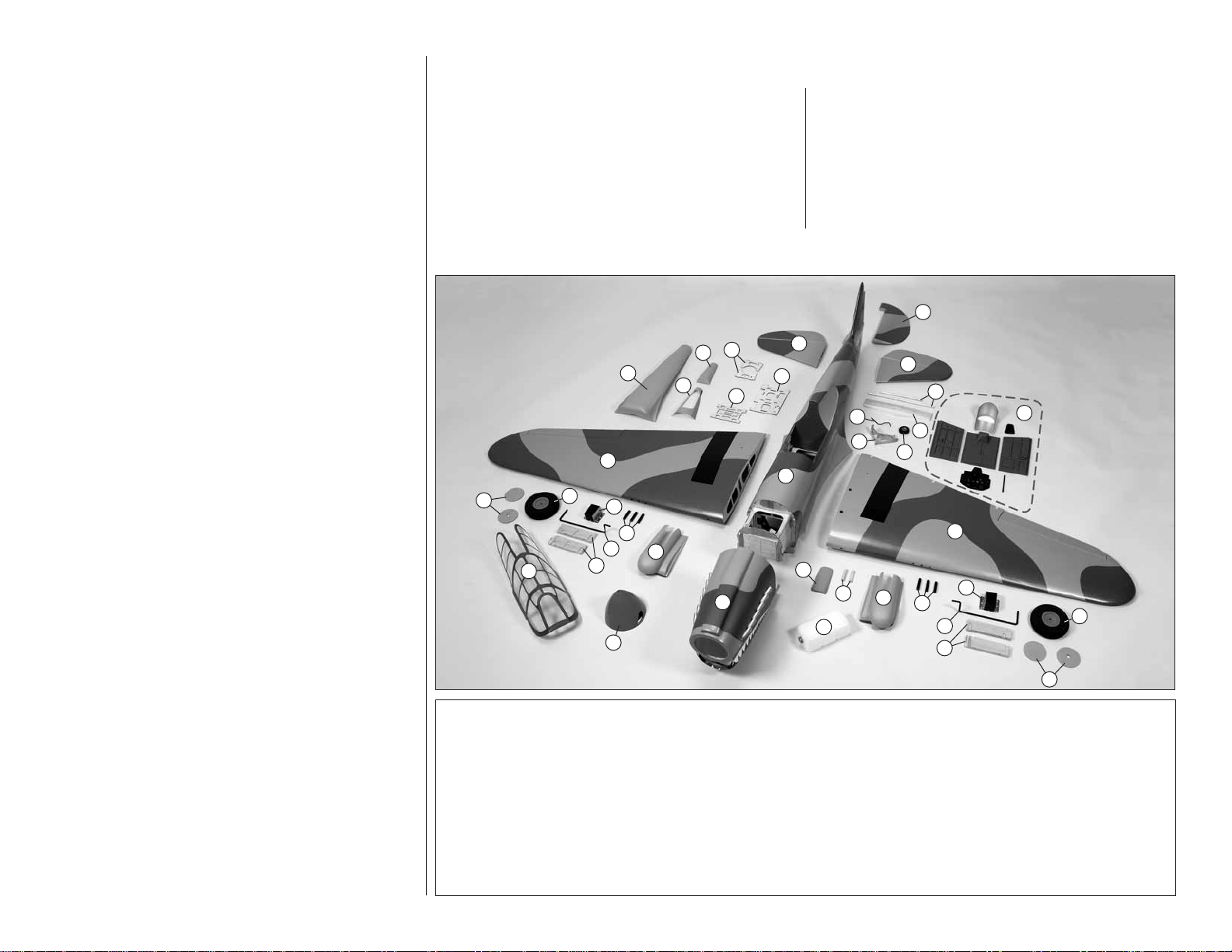
KIT CONTENTS
23
21
20
1
9
1. Right Wing w/ Aileron & Flap
2. Left Wing w/ Aileron & Flap
3. Fuselage
4. Cowl
5. Canopy
6. Right Stabilizer & Elevator
7. Left Stabilizer & Elevator
8. Rudder
9. Wheel Covers
10. Wheels
11. Landing Gear Blocks
10
15
14
12
5
11
16
22
13
4
12. Landing Gear Wire
13. Wheel Nacelles
14. Machine Gun Tubes
15. Landing Gear Mount
16. Spinner
17. Cowl Extension
18. Fuel Tank
19. Leading Edge Dowel
20. Belly Pan
21. Rear Belly Pan
22. Tail Wheel Cover
24
25
3
Top Flite Product Support
3002 N Apollo Drive, Suite 1
Champaign, IL 61822
Ph: (217) 398-8970, ext. 5
Fax: (217) 398-7721
E-mail: airsupport@top-fl ite.com
8
6
7
26
28
29
17
19
18
30
27
2
13
15
14
12
11
23. Air Tank Support
24. Servo/Receiver Tray
25. Ignition/Battery Tray
26. Stab Tubes (2)
27. Tail Wheel
28. Tail Wheel Wire
29. Tail Wheel Bracket
30. Wing Joiner
31. Cockpit Components
31
10
9
5
Page 6
ORDERING REPLACEMENT PARTS
Replacement parts for the Top Flite Giant Scale P-40
ARF are available using the order numbers in the
Replacement Parts List that follows. The fastest, most
economical service can be provided by your hobby
dealer or mail-order company.
To locate a hobby dealer, visit the Top Flite web site at
www.top-fl ite.com. Select “Where to Buy” in the menu
across the top of the page and follow the instructions
provided to locate a U.S., Canadian or International dealer.
Parts may also be ordered directly from Hobby Services
by calling (217) 398-0007, or via facsimile at (217) 3987721, but full retail prices and shipping and handling
charges will apply. Illinois and Nevada residents will also
be charged sales tax. If ordering via fax, include a Visa®
or MasterCard® number and expiration date for payment.
Mail parts orders Hobby Services
and payments by 3002 N Apollo Drive, Suite 1
personal check to: Champaign IL 61822
Be certain to specify the order number exactly as listed
in the Replacement Parts List. Payment by credit card
or personal check only; no C.O.D.
If additional assistance is required for any reason
contact Product Support
by e-mail at or by telephone at
productsupport@top-fl ite.com (217) 398-8970
SpinnerTOPA1804
DecalsTOPA1805
Cockpit KitTOPA1806
Belly Pan and Aft FairingTOPA1807
Tail Gear CoverTOPA1808
PREPARATIONS
1. If you have not done so already, remove the major
❏
parts of the kit from the box and inspect for damage.
If any parts are damaged or missing, contact Product
Support at the address or telephone number listed in
the “Kit Inspection” section on page 5.
Begin with your right wing panel fi rst so your assembly
matches the photos in the manual.
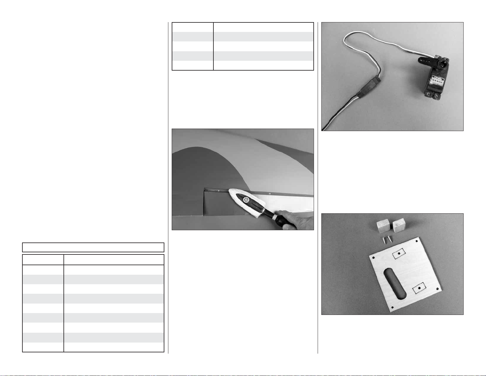
1. Install a 24" [610mm] servo extension to your
❏ ❏
aileron servo. Secure it with heat shrink tubing, tape
or other method for securing them together.
2. Install a 12" [305] servo extension to your fl ap
❏ ❏
servo. Secure it with heat shrink tubing, tape or other
method for securing them together.
REPLACEMENT PARTS LIST
Order No. Description
FuselageTOPA1795
WingTOPA1796
Stab and ElevatorsTOPA1797
RudderTOPA1798
CowlTOPA1799
CanopyTOPA1800
Fixed Landing Gear WiresTOPA1801
Landing Gear Nacelle SetTOPA1802
Tail Wheel BracketTOPA1803
2. Use a covering iron with a covering sock on high
❏
heat to tighten the covering if necessary. Do this for
all of the components of the model. Apply pressure
over sheeted areas to thoroughly bond the covering
to the wood.
ASSEMBLE THE WING
Note: Throughout this instruction manual you will be
instructed to use screws to secure different parts. In
all cases, whenever a screw is threaded into wood
sheeting or wood blocks we recommend that y ou install
the screw and then remove it. Apply a drop of thin CA
glue into the hole to harden the threads. After the glue
has hardened, re-install the screw . Follo wing this step
will insure that you have a solid thread f or you scre ws.
6
3. Remove the tape holding the servo covers
❏ ❏
to the bottom of the wing. Locate two 5/16" × 1/2" ×
3/4" [8mm × 13mm × 19mm] hardwood blocks. The
markings on the back of the cover are correct for
Page 7
Futaba servos. Place your particular brand of servo on
the cover making sure they fi t between the locations
for the blocks. Adjust the positioning of the blocks for
your brand of servo.
4. Glue the blocks to the servo cover. Once the
❏ ❏
glue has cured, drill a 1/16" [1.6mm] hole through the
cover and into the servo mounting blocks. Secure the
block to the cover with a #2 × 3/8" [#2 × 9.5mm] wood
screw. Do this for both of the servo covers.
6. Install the servo arms onto your servos. The
❏ ❏
aileron servo will require a 1" [25mm] servo arm to get
the required aileron throw. A standard length arm will
work for the fl ap. Place your servo onto the mounting
blocks. Drill a 1/16" [1.6mm] hole through the servo
mounting tabs into the mounting blocks. Secure the
servos to the mounting blocks with the screws that
came with your servos.
5. Inside the aileron and fl ap servo compartments
❏ ❏
you will fi nd a string. Tie the string to the servo lead.
The other end of the string is taped to the root wing
of the rib. Pull the leads through the wing.
7. Install the servo covers to the wing securing
❏ ❏
them to the wing with four #2 × 3/8" [9.5mm] screws
and four #2 fl at washers.
7
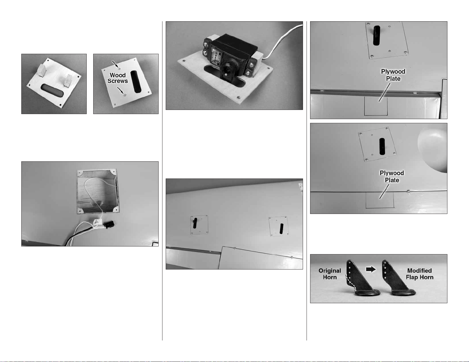
8. Located in both the aileron and the fl ap is
❏ ❏
a plywood mounting plate. If you look at the control
surface at a slight angle you will be able to see the
plate through the covering.
9. The fl ap and aileron will each require a black
❏ ❏
nylon control horn. The fl ap control horn needs to be
modifi ed. Cut a control horn as shown. A high-speed
motor tool works well for this.
Page 8
10. Place a black nylon control horn onto the
❏ ❏
plywood mounting plate in the aileron in line with the
servo arm. Drill a 3/32" [2.4mm] hole through each
of the holes in the control horn. Drill only through the
plywood plate. Do not drill through the top of the
control surface. Mount the horn with four #4 × 3/8"
screws.
11. Install the modifi ed control horn to the fl ap
❏ ❏
using the same method used for the aileron.
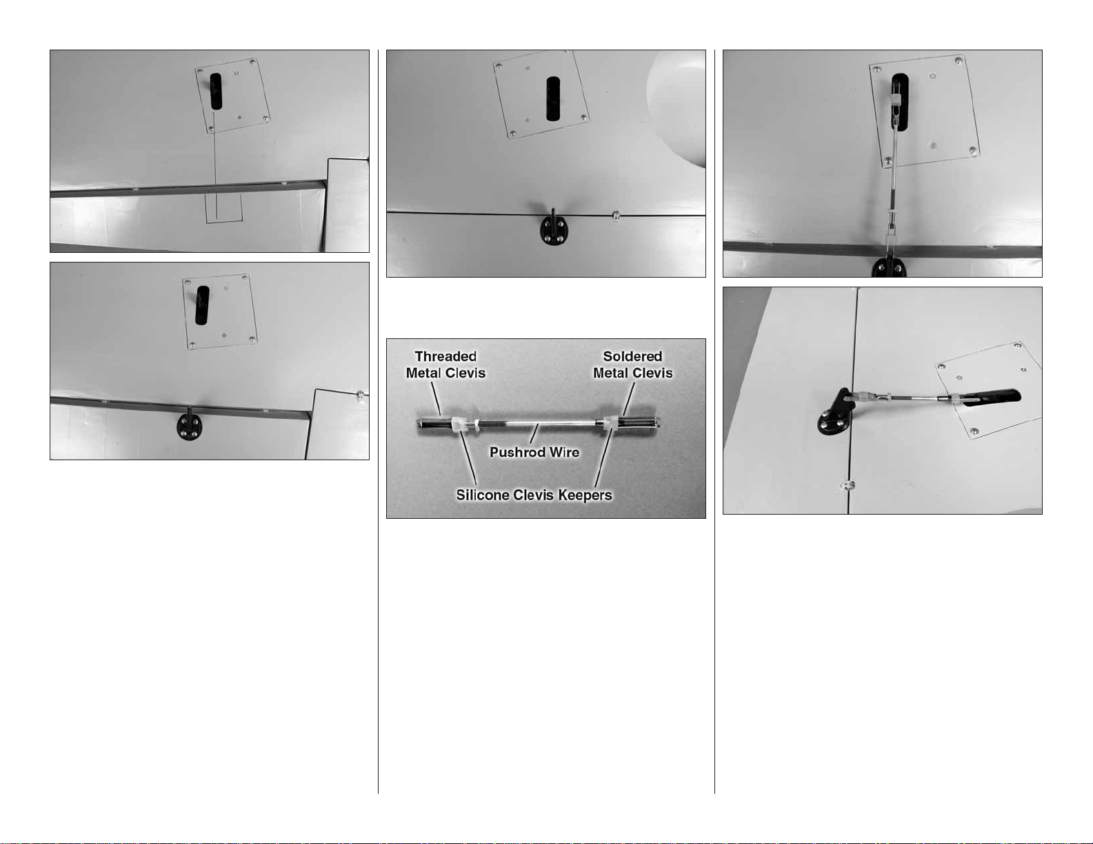
12. Each aileron and fl ap pushrod is made from
❏ ❏
a 5-3/4" [146mm] pushrod wire threaded on one end,
a threaded metal clevis, a 4-40 nut, a metal solder
clevis and two silicone clevis keepers.
13. Screw the 4-40 nut and the threaded metal
❏ ❏
clevis onto the pushrod wire. Attach the clevis to the
third hole from the bottom of control horn. Attach the
metal solder clevis into the outer hole of the aileron
servo arm. Center the aileron servo arm and the aileron.
Mark on the pushrod wire where to cut the wire. Remove
all of the pushrod wire components. Solder the metal
solder clevis to the pushrod. If you are not familiar with
soldering, follow the “Hot Tip” that follows. After the
solder cools, apply threadlocker to the threaded wire
and tighten the nut against the clevis.
8
Page 9
HOW T O SOLDER
1. Use denatured alcohol or other solvent to
thoroughly clean the pushrod. Roughen the end of
the pushrod with coarse sandpaper where it is to
be soldered.
2. Apply a few drops of soldering fl ux to the end of
the pushrod, then use a soldering iron or a torch
to heat it. “Tin” the heated area with silver solder
by applying the solder to the end. The heat of the
pushrod should melt the solder – not the fl ame of
the torch or soldering iron – thus allowing the solder
to fl ow. The end of the wire should be coated with
solder all the way around.
3. Place the clevis on the end of the pushrod. Add
another drop of fl ux, then heat and add solder. The
same as before, the heat of the parts being soldered
should melt the solder, thus allowing it to fl ow. Allow
the joint to cool naturally without disturbing. Avoid
excess blobs, but make certain the joint is thoroughly
soldered. The solder should be shiny, not rough. If
necessary, reheat the joint and allow to cool.
4. Immediately after the solder has solidifi ed, but
while it is still hot, use a cloth to quickly wipe off the
fl ux before it hardens. Important: After the joint cools,
coat the joint with oil to prevent rust. Note: Do not
use the acid fl ux that comes with silver solder for
electrical soldering.
This is what a properly soldered clevis looks
like – shiny solder with good flow, no blobs and
flux removed.
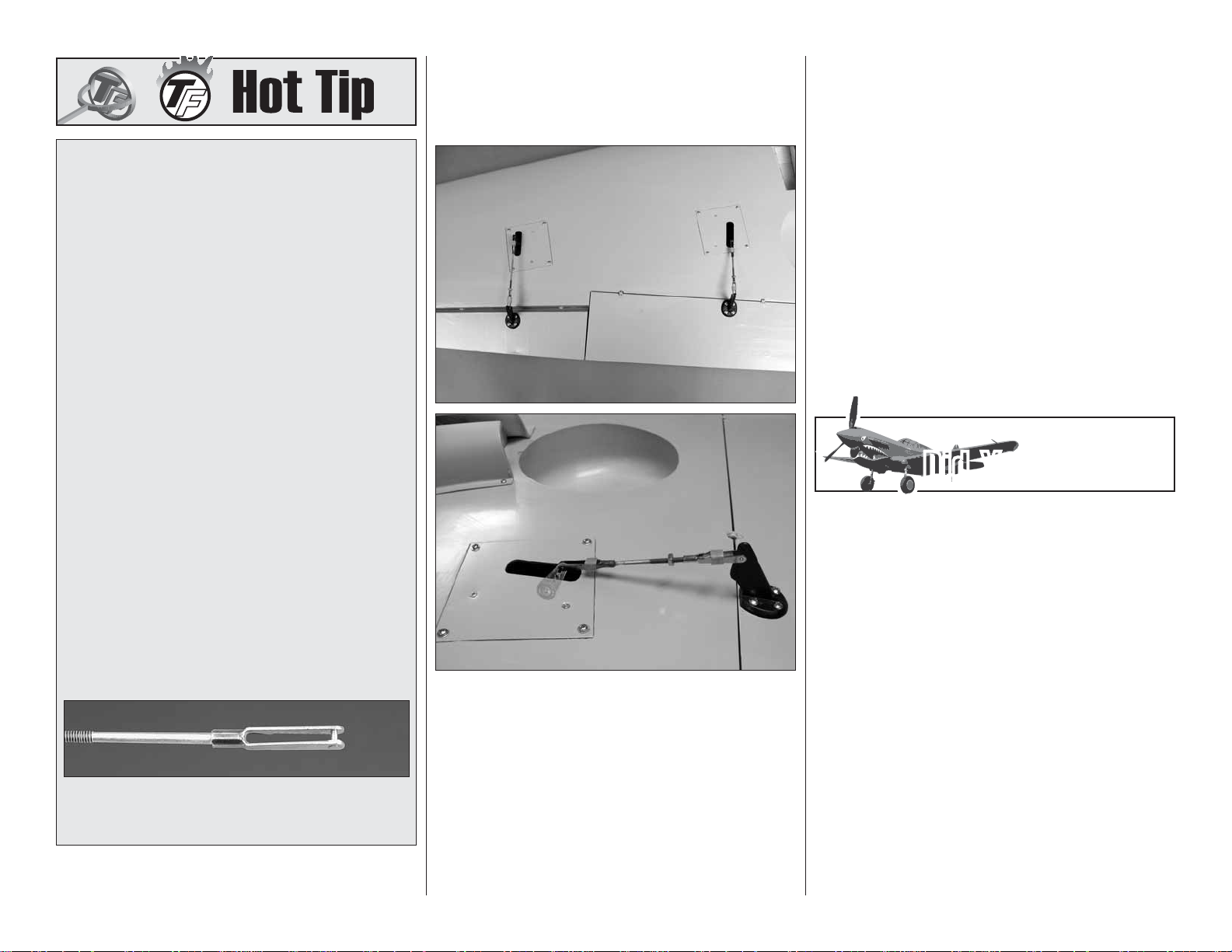
14. Once the solder has cooled slide a silicone
❏ ❏
clevis keeper over each clevis. Install the pushrod
wire assembly to the aileron servo arm and aileron
control horn.
15. Use the same procedure for the fl ap servo
❏ ❏
except you will not center the servo. Instead, make sure
the fl ap is fully closed to the bottom of the wing. Then,
position the servo arm so that it is rotated toward the
wing trailing edge. Now you can proceed with making
the pushrod wire assembly.
16. Repeat steps 1-15 for the left wing.
❏
You now need to make a decision on the type of
landing gear you will be installing. We provide fi xed
wire landing gear as part of the kit. The retractable
rotating landing gear that is available from Robart
really is a great addition to the looks and the realism of
this airplane. You can choose to install the fi xed landing
gear and upgrade to the Robart landing gear in the
future if you wish to. Both gears are interchangeable
in the mount.
If you will be installing the fi xed wire landing gear,
continue with the next step. If you will be installing the
retractable landing gear, skip ahead to the next section.
“INSTALL THE RETRACTABLE LANDING GEAR”.
Did You Know?…Did You Know?…
The P-40 was a relatively clean design, and was
unusual for its time in having a fully retractable tail
wheel. One hundred and ninety-seven P-40s were
built in 1939-40 for the USAAF, and many more were
sold abroad to Britain and France.
INST ALL THE FIXED WIRE
LANDING GEAR
IMPORTANT! The fi rst step in the installation of the
landing gear is to identify which blocks go into each
wing half. This is the most critical part of the landing
gear installation. If you ever choose to upgrade to the
Robart retractable landing gear, the blocks must be
installed as shown.
9
Page 10
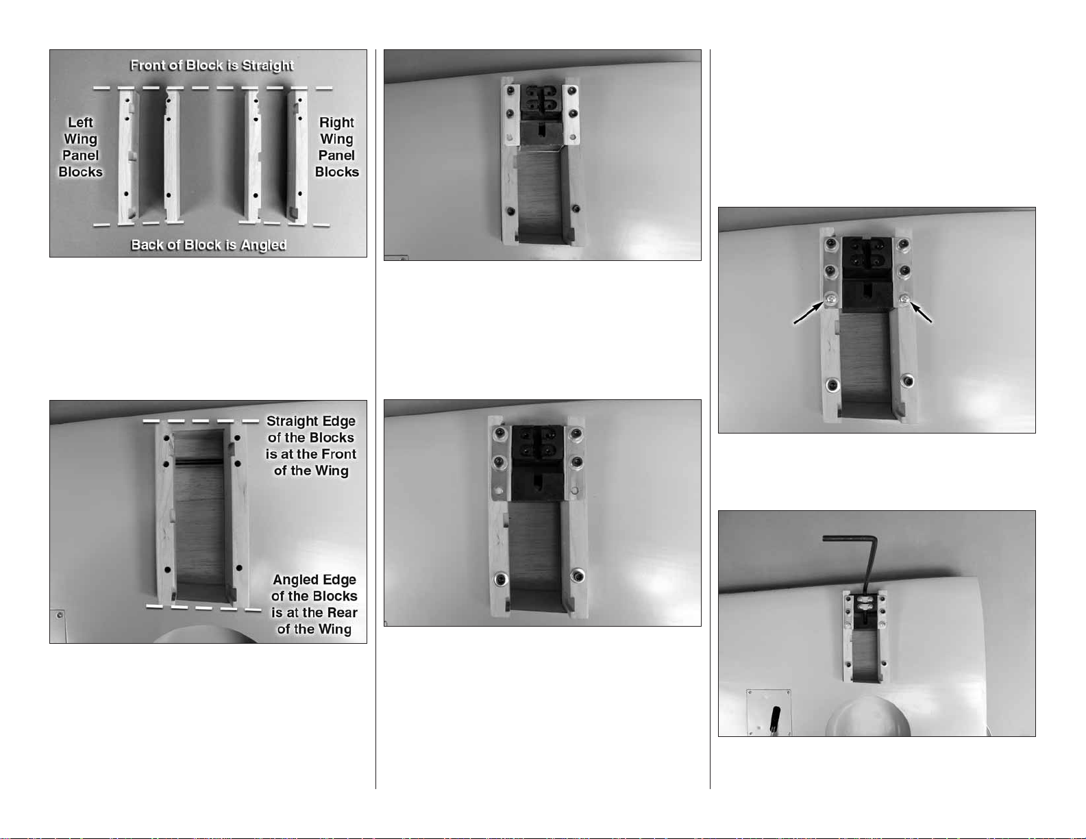
1. Locate the four hardwood landing gear
❏ ❏
blocks. Place them on you work bench exactly as
shown in the picture. You will notice that the front of
the block is square and the back of the block is angled.
You will also notice that there are a number of router
cuts in the blocks. Examine the picture closely to be
sure the blocks are just as shown in the picture.
3. Install one of the aluminum/fi ber landing
❏ ❏
gear mounts between the landing gear blocks.
Temporarily secure the landing gear block and the
landing gear mount with six 8-32 × 2-1/2" [64mm]
socket head cap screws.
4. Repeat steps 1-3 for the left wing panel.
❏
bolts or blind nuts, it will be very diffi cult to remove the
mounting bolts. As a precaution, you might consider
applying a small amount of petroleum jelly or lightweight
oil to the threads of the bolts before installing them.
Place the wood blocks in position on the rails. Place
the aluminum/fi ber landing gear block between the
mounts. Secure the components to the wing with six
8-32 × 2-1/2" [64mm] socket head cap screws, #8 fl at
washers and #8 lock washers.
2. Install the blocks for the right wing panel into
❏ ❏
the opening as shown. If you have the correct blocks,
the angled end of the block should match the angle
of the opening in the wing.
5. Double-check both of the landing gear block
❏ ❏
installations to be sure they are correct. When you are
satisfi ed with the installation remove the bolts from the
right wing panel. Mix a 1/2 ounce [4 drams] of 30-minute
epoxy. Use an epoxy brush to apply a fi lm of glue to
the bottom of the landing gear mounting blocks and
to the rails in the wing as well as the sides of the box
the mounts slide into. Be careful not to get glue into
the blind nuts. If you get glue into the threads of the
10
6. Drill a 7/64" [2.8mm] hole through each of the
❏ ❏
two rear mounting holes of the landing gear. Insert two
#6 × 1/2" screws, #6 lock washers and #6 fl at washers.
7. Insert the landing gear wire into the hole in
❏ ❏
the landing gear block. The axle of the wire must be
Page 11
pointing toward the wing tip. If it does not, you have the
wrong wire. Install two aluminum landing gear straps
into the block and screw them to the block with four
#6 × 1/2" [13mm] screws.
10. At the location of the wheel collars make a
❏ ❏
fl at spot on the axle. A high-speed motor tool or small
fi le works well for this.
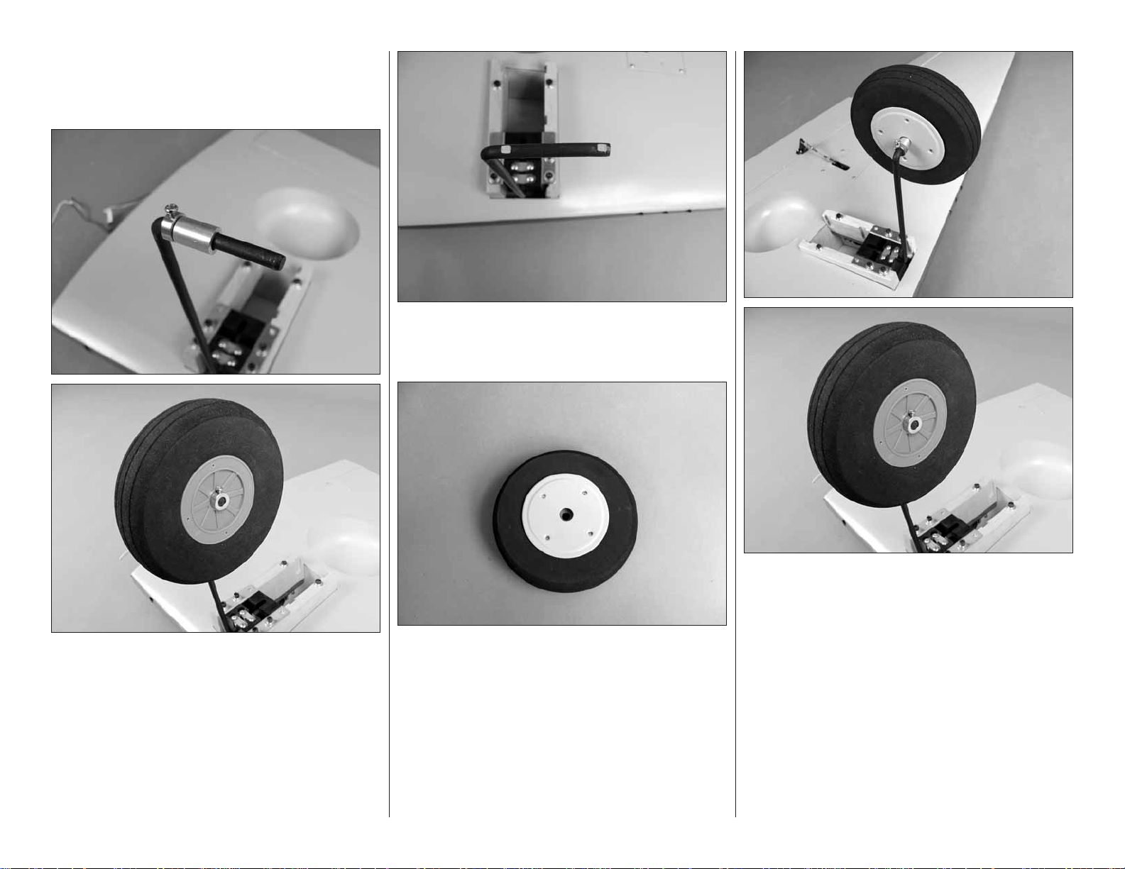
8. Slide a 6mm [15/64"] wheel collar onto the axle
❏ ❏
followed by a 5/8" [16mm] long aluminum tube. Slide
the wheel onto the axle. Insert a 3mm × 5mm phillips
head screw into another 6mm wheel collar and then
secure the wheel collar to the end of the axle.
9. Slide the aluminum tube and the wheel collar
❏ ❏
on the inside of the wheel against the wheel. Mark the
location of the wheel collars onto the axle and remove
the wheel, collars and aluminum tube.
11. Locate two of the wheel covers and the wheel.
❏ ❏
Screw the wheel cover with the large hole into the
pre-drilled holes in the wheel with four 2mm × 4mm
Philips head screws.
11
12. Slide one of the 6mm wheel collars with the
❏ ❏
3mm × 5mm phillips head screw threaded into it onto
the axle, followed by the 5/8" [16mm] long aluminum
tube. Slide the wheel onto the axle and another wheel
collar and set screw. Apply threadlocker to the set
screws, then tighten the set screws in the wheel collars
against the fl at spot you made in the axle.
Page 12
13. Secure the outer wheel cover to the wheel
❏ ❏
with four 2mm × 4mm Philips head screws.
14. Repeat steps 5-13 for the left wing panel.
❏
If you have installed the fi xed wire landing gear, skip
ahead to “MOUNT THE WING NACELLES”
INST ALL THE RETRA CT ABLE
LANDING GEAR
IMPORTANT! The fi rst step in the installation of the
landing gear is to identify which blocks go into each
wing half. This is the most critical part of the landing
gear installation. If these blocks are not installed
properly the landing gear will not fi t properly into all
of the cut-outs in the blocks. Follow these instructions
exactly to insure the landing gear will fi t properly.
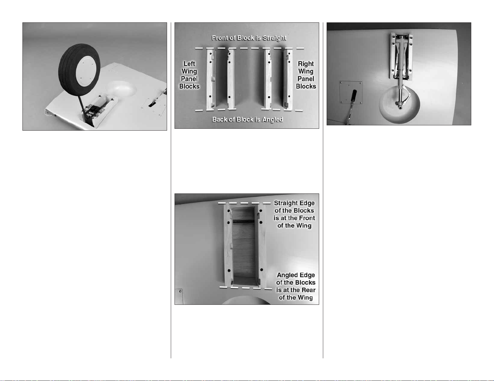
1. Locate the four hardwood landing gear
❏ ❏
blocks. Place them on your work bench exactly as
shown in the picture. You will notice that the front of
the block is square and the back of the block is angled.
You will also notice that there are a number of router
cuts in the blocks. Examine the picture closely to be
sure the blocks are just as shown in the picture.
2. Install the blocks for the right wing panel into
❏ ❏
the opening as shown. If you have the correct blocks
the angled end of the block should match the angle
of the opening in the wing.
3. Install the right side landing gear between
❏ ❏
the mounting blocks. The landing gear fi ts between
the blocks best if you install it with the gear retracted.
Mount the landing gear and the blocks with six 8-32 ×
2-1/2 [64mm] socket head cap screws, #8 fl at washers
and #8 lock washers.
4. Repeat steps 1-3 for the left wing panel.
❏
5. Double check both of the landing gear block
❏ ❏
installations to be sure they are correct. Make sure
that the landing gear move smoothly in and out of
the wing. When you are satisfi ed with the installation
remove the bolts and the landing gear from the right
wing panel. Mix a 1/2 ounce [4 drams] of 30-minute
epoxy. Use an epoxy brush to apply a fi lm of glue to
the bottom of the landing gear mounting blocks and to
the rails in the wing as well as the sides of the box the
mounts slide into. Be careful not to get glue into the
blind nuts. If you get glue into the threads of the bolts or
blind nuts it will be very diffi cult to remove the mounting
bolts. As a precaution you might consider applying a
small amount of petroleum jelly or lightweight oil to the
threads of the bolts before installing them. Place the
blocks in position on the rails. Place the landing gear
between the mounts. Secure the components to the
wing with six 8-32 × 2-1/2" [64mm] socket head caps
screws, #8 fl at washers and #8 lock washers.
6. Repeat step fi ve for the left wing. Set the wings
❏ ❏
aside and allow the glue to cure. Move onto the next
step after the glue has completely cured.
12
Page 13

7. Remove the landing gear from the right wing
❏ ❏
panel.
8. If you have purchased the Robart air pressure
❏ ❏
tubing, cut a piece of the red and blue line to a length
of 18" [457mm]. Cut the remaining line in half, leaving
you with two red and purple lines approximately 20"
[508mm] long.
9. Install the purple line to the fi tting on the front
❏ ❏
of the air cylinder and the red line to the rear fi tting.
11. Locate a wheel, the 5/8" [16mm] long
❏ ❏
aluminum tube and the axle included with the landing
gear. Slide the axle into the wheel and slide the
aluminum tube over the axle.
14. Determine where the set screw makes contact
❏ ❏
with the axle. Make a fl at spot on the axle with a fi le
or motor tool.
15. Locate two of the wheel covers and the wheel.
❏ ❏
Screw the wheel cover with the large hole into the
pre-drilled holes in the wheel with four 2mm × 4mm
Philips head screws.
10. Re-install the landing gear to the blocks with
❏ ❏
the six 8-32 × 2-1/2" [64mm] socket head cap screws,
#8 fl at washers and #8 lock washers. Pull the air line
through the wing, exiting at the wing root.
12. Slide the wheel and axle into the landing
❏ ❏
gear. Make a mark on the axle where it needs to be
cut to make it fl ush with the landing gear.
13. Cut off the end of the axle. A high-speed
❏ ❏
motor tool and cut off wheel works well for this.
13
16. Slide the axle into the wheel from the side
❏ ❏
without the wheel cover; then, slide the aluminum tube
over the axle.
Page 14

17. Insert the axle and wheel into the landing gear.
❏ ❏
Apply a drop of threadlocker onto the set screw; then,
tighten the set screw against the fl at spot on the axle.
18. Install the remaining cover to the outside of
❏ ❏
the wheel with four 2mm × 4mm Philips head screws.
19. Repeat steps 7–18 for the left wing panel.
❏
MOUNT THE WING NA CELLES
1. Examine the two fi berglass landing gear
❏ ❏
nacelles and determine which goes on each wing.
Drill four 5/64" [2mm] holes through the fl ange on each
side of the nacelle as shown.
2. Place the right nacelle over the landing gear
❏ ❏
on the right wing. Be sure to center the nacelle to the
landing gear. Once you are satisfi ed with the location.
Drill a 1/16" [1.6 mm] hole through each of the holes
in the fl anges, into the wing surface.
3. Insert and then remove a #2 × 3/8" [9.5mm]
❏ ❏
screw into each of the holes in the wing. Around each
of the holes you made pierce four holes with a pin.
Apply a drop of thin CA glue into the holes, allowing
the glue to harden the threads you just made in the
balsa wing skin. Allow the glue to cure.
4. Mount the nacelle to the wing with eight #2
❏ ❏
× 3/8" [9.5mm] screws. In our model development we
found that the procedure of strengthening the wood
with thin CA allowed the nacelles to be held securely
by the screws. If you feel that your engine may have
excessive vibration potentially causing the screws to
back out, or would like to add extra holding strength to
the nacelles you can apply a thin bead of R/C 56 glue
to each fl ange. If you should ever need to remove the
nacelle you can slide a knife blade under the fl ange
to free the glue bond.
14
5. Repeat steps 1– 4 for the left wing.
❏
Page 15

JOIN THE WING HAL VES
1. Glue the 1/4" ×
❏
3/4" [6mm × 19mm]
dowel into the hole
at the rear of the
root rib in the right
wing.
2. You will see two holes in the left wing panel. These
❏
holes are to allow the servo leads and the air lines to
exit the wing. Important: Be sure that you feed all of
the servo leads and all of the air lines through these two
holes before gluing the wings together in the next step .
4. When you are satisfi ed with the fi t of the joiner, glue
❏
the joiner into the wing joiner pockets with 30-minute
epoxy. When gluing the wings together be sure that
you use plenty of glue in the joiner pockets, the joiner
and the root ribs of the wing. Use masking tape to hold
the wings together while the glue cures.
6. Mount the wing to the fuselage with the two 1/4-
❏
20 × 2" [51mm] nylon wing bolts. Locate the fi berglass
belly pan. Place it on the wing. With a fi ne-tip felt pen,
mark the location on the wing for the belly pan.
3. Locate the har dwood wing joiner and examine
❏
these pictures to understand how to install the joiner
into the wings. Test fi t the joiner into the wings.
5. Test fi t the two 3/8" × 2" [9.5mm × 51mm] wood
❏
dowels into the two holes in the leading edge of the
wing. Place them into the holes so that 3/4" [19mm] of
the dowel extends out of the wing. Make a mark on the
dowel to indicate this distance. Remove the dowel; then,
apply epoxy into the holes and on the dowel. Slide the
dowel into the hole leaving 3/4" [19mm] extending from
the wing. Clean off any excess epoxy with denatured
alcohol and a paper towel.
15
7. Following the instructions for cutting MonoKote
❏
in the “Hot Tip” that follows, carefully cut the covering
from the wing, making sure you do not cut the wing skin.
IMPORTANT: Cutting the wing skin will severely
weaken the structure.
Page 16

HOW TO CUT COVERING FROM BALSA
Use a soldering iron to cut the covering from the
stab. The tip of the soldering iron doesn’t have to be
sharp, but a fi ne tip does work best. Allow the iron to
heat fully. Use a straightedge to guide the soldering
iron at a rate that will just melt the covering and not
burn into the wood. The hotter the soldering iron,
the faster it must travel to melt a fi ne cut. Peel off
the covering.
9. Apply epoxy to the belly pan fl ange. Then glue
❏
the belly pan in place on the fuselage. Tape the belly
pan in place until the glue cures.
11. Locate six 3/8" × 1-3/4" [9.5mm × 44mm] black
❏
tubes. These tubes replicate the machine guns. Test
fi t a tube into each of the holes in the leading edge
of the wing. Once you are satisfi ed with the fi t, glue a
tube into each hole. Leave 3/8" of the tube extending
beyond the leading edge of the wing.
8. Lightly scuff the fl ange of the fi berglass belly pan
❏
with 220-grit sandpaper. Wipe off the residue with a
paper towel wetted with denatured alcohol.
10. Locate the rear fi berglass bell y pan and place
❏
it in position on the fuselage behind the belly pan you
just glued in place. Mark the location on the fuselage
and cut the covering away using the same technique
used for the main belly pan. Glue the rear belly pan
in place. Tape it in place behind the main belly pan.
You should maintain a gap between the belly pans of
3/32" [2.4mm]. After the glue has cured remove the
wing from the fuselage.
16
12. Install the Robart T-fi ttings and quick connect air
❏
line connectors to the air lines from the landing gear.
Page 17

Did You Know?…Did You Know?…
In the middle of 1941, General Claire Chennault began
recruiting for his Volunteer Group–better known as the
Flying Tigers –to fi ght the Japanese from China, for
which 100 P-40s were ordered for purchase through
a loan from the U.S. Government.
ASSEMBLE THE FUSELA GE
INST ALL THE STABILIZER
1. Test fi t the two aluminum stabilizer tubes in the
❏
fuselage and slide the stabilizers onto the tubes. The
shorter tube goes in the front hole. If the aluminum
tubes are too tight to slide through the holes, take
a sharp hobby knife and gently scrape the inside of
the holes. During the manufacturing process a small
amount of resin or fi ller may be left behind in the hole.
2. Once you are satisfi ed with the fi t of the stabilizer
❏
halves, remove the stabilizer halves and joiner tubes.
Use medium grit sandpaper to roughen up the
aluminum tubes. Clean the tubes with denatured
alcohol and insert both tubes back into the fuselage
until the end exits on the opposite side by approximately
1" [25.4mm].
3. Gather everything required for gluing the stabilizer
❏
halves to the fuselage, including 30-minute epoxy,
mixing sticks, epoxy brush, 12" [305mm] long dowel
or wire, masking tape, denatured alcohol and small
paper towel squares. Mix up 3/4 oz. [22cc] of 30-minute
epoxy. Apply a generous amount of epoxy to the long
side of the aluminum joiner tubes. Pull the tubes
through the fuselage so that they are close to centered.
Pour a small amount of epoxy into both holes of one
of the stabilizer halves. Using a dowel or wire, coat
the inside of the holes. Apply epoxy to the root rib of
the stabilizer and the fuselage. Insert the end of the
aluminum tubes with epoxy on them into the stabilizer
and press the stabilizer against the fuselage. Wipe off
any excess epoxy that may have squeezed out before
it runs down the fuselage. Quickly repeat the process
on the other side. Wipe off any excess epoxy with a
dampened paper towel and denatured alcohol. Use
pieces of masking tape to hold the stabilizer halves
tight against the fuselage until the epoxy cures.
4. Without using any glue, install three hinges into
❏
the holes in the trailing edge of the fi n. Note that the
pivot point of each hinge must align with the center of
the trailing edge. To achieve this alignment, the hinges
will be fairly deep in the fi n. Also note that the hinges
must be perpendicular to the leading edge.
5. Again without glue, test fi t the rudder to the fi n.
❏
Remove the rudder and all the hinges. Add a small drop
17
Page 18

of oil to the pivot point on the hinges. This will prevent
the epoxy from adhering to the pivot point. Make sure
oil does not get on the gluing surface of the hinge.
If it does, clean the oil off with a paper towel square
dampened with denatured alcohol.
6. Mix up approximately 1/4 oz. [7.4cc] of 30-minute
❏
epoxy. Use a toothpick to thoroughly apply the epoxy in
the holes in the fi n and rudder. Use the toothpick to get
the epoxy out of the opening of the holes in the rudder
and fi n so it doesn’t get into the hinge pin. Wipe away
any excess epoxy around the outside of the holes with
a couple of the small paper towel squares dampened
with denatured alcohol.
7. Use the toothpick to apply epoxy to the ends
❏
of the rudder hinges that go into the fi n. Insert each
hinge into the fi n and wipe away any excess epoxy
that squeezes out of the hole.
gear. The two tail gears are interchangeable; you can
install the fi xed gear and upgrade to the retractable
gear later if you wish. Proceed to "Mount the Fixed
Tail Gear" or if you will be installing the retractable tail
gear skip ahead to, “Mount the Retractable Tail Gear”.
MOUNT THE FIXED TAIL GEAR
the top of the tail gear wire and perpendicular to the
tail wheel. Also, remove the two nuts from the top of
the tail gear, apply threadlocker and reinstall the nuts.
2. Enlarge the holes in the steering arm with a 5/64"
❏
[2mm] drill bit. Mount a 2-56 ball link ball to each arm
with a 2-56 nut and a drop of threadlocker.
3. Skip to step 6 in “Mount the Retractable Tail
❏
Gear” and follow the steps for installing the pull-
pull cable.
8. Apply epoxy to the other end of the hinges. Join
❏
the rudder to the fi n, pushing the hinges only about
3/4 of the way into the rudder. Use a toothpick to wipe
away any epoxy that squeezes out. Then push the
rudder the rest of the way in.
9. Move the rudder left and right to align the hinges.
❏
If needed, use a length of masking tape to hold the
rudder to the fi n. Allow the glue to fully cure.
INST ALL THE T AIL GEAR ASSEMBL Y
We have provided instructions for the installation of the
fi xed tail gear assembly and the Robart retractable tail
1. Slide a 3.5mm wheel collar on the tail gear wire.
❏
Insert the tail gear wire in the tail gear mount. Install
a second wheel collar followed by the steering arm
on the tail gear wire. Apply a drop of threadlocker on
three 3mm × 6mm machine screws. Secure the two
wheel collars and the steering arm to the tail gear wire
with the three 3mm × 6mm machine screws. Adjust
the location of the steering arm so that it is fl ush with
18
MOUNT THE RETRACTABLE TAIL GEAR
1. Remove the steering arm from the Robart
❏
#160LWC retractable tail gear assembly (not included).
File a fl at spot near the top of the shaft for the set screw
Page 19

in the steering arm to lock onto. Mount the steering
arm to the shaft with a drop of threadlocker and the
set screw.
2. File another fl at spot near the bottom of the
❏
shaft for one of the set screws in the strut. Tighten
both set screws with a drop of threadlocker on each.
Be certain the steering arm and the axle in the strut
remain parallel with each other. Make adjustments to
the fl at spots if necessary.
3. Enlarge the center hole in both sides of the
❏
steering arm with a 3/32" [2.4mm] drill.
5. Insert a 2-56 ball link ball in the hole. Secure
❏
each ball with a 2-56 nut and a drop of threadlocker
6. Use wire cutters to cut the supplied braided cable
❏
into two equal lengths. Slide a small copper tube (called
a swage) over one end of the cables, then guide the
end of the cable back through.
8. Use pliers to pull the cable from the fi rst loop to
❏
reduce the size of the second loop.
9. Now pull on the long end of the cable to reduce
❏
the size of the fi rst loop. Slip the loop over one of the
ball link balls on the steering arm. Tighten the loop
until it is small enough to remain secure on the ball,
yet may still be pried off. Squeeze the swage with
pliers. Connect the other cable to the other ball link
ball the same way.
4. Cut off the part of the steering arm outside of the
❏
center hole and re-shape the end ot the steering arm.
7. Wrap the cable back around the swage and back
❏
through the swage.
19
10. Retractable tail gear only: Connect 40"
❏
[1016mm] of purple air line to the forward air fi tting
Page 20

and 40" [1016mm] of red air line to the aft fi tting on
the air cylinder. There is not enough air line left over
from the main gear, so additional line will have to be
purchased separately (Robart #169 Pressure Tubing).
11. Place the tail gear (fi xed or retractable) in the
❏
fuselage while simultaneously guiding the pull/pull cable
through the white plastic guide tubes. If installing the
retractable tail gear, also guide the air lines through
the fuselage.
12. Drill four 3/32" [2.4mm] holes through the rails
❏
for mounting the tail gear. If your drill bit is not long
enough to reach the rail nearest the top of the fuselage,
use medium CA to temporarily glue a 3/32" [2.4mm]
drill bit in a 1/8" [3.2mm] brass tube. After drilling the
holes, the drill bit can be removed from the tube by
heating the tube.
14. Locate the fi berglass tail gear cover. Place it
❏
onto the fuselage making sure you align the color
markings on it to the markings on the fuselage. Drill
three 1/16" [1.6mm] holes into each side of the cover,
drilling through the fuselage. Secure the cover with
six #2 × 3/8" [9.5m] screws. It is recommended that
you harden these screw holes in the balsa fuselage
with thin CA to be assured the threads are strong.
Follow the technique provided on page 6. ("Assemble
the Wing")
INST ALL THE ELEVA T OR
& RUDDER SERVOS
1. Cut two 4-40 × 48" [1220mm] metal pushrods to
❏
a length of 30" [762mm]. Insert the pushrods into the
upper pushrod exit holes on each side of the fuselage
as shown in the photo.
13. Mount the tail gear in the fuselage with four
❏
#6 × 1/2" [12.7mm] sheet metal screws. Enlarge the
center hole through the 1-3/4" [44mm] tailwheel with
a #9 [5mm] drill. Cut the axle included with the Robart
retractable tail gear to the correct length; then, fi le a
fl at spot on it and mount it to the strut.
Did You Know?…Did You Know?…
The P-40 Warhawk was a deadly fi ghting machine in
trained hands. The formidable armament of 6 × 12.7mm
(.50 caliber) machine guns (up to 200 rounds per gun)
was complemented by the ability of the aircraft to carry
a bombload for an increasingly expanding workload.
20
2. Thread a 4-40 nut, threaded clevis and a silicone
❏
clevis retainer, 12 turns, onto both elevator pushrods.
Page 21

3. Draw a straight line from the lower pushrod hole
❏
to the rudder to indicate the position for the rudder
control horn. Repeat on the other side of the fuselage
and rudder.
4. Mount the control horns to the elevators and
❏
the rudder. Follow the same procedure used for the
ailerons, by drilling 3/32" [2.4mm] holes and using #4 ×
1/2" [12.7mm] sheet metal screws. Attach the elevator
clevis in the third hole from base of the control horn.
Don’t forget to harden the holes with thin CA after fi rst
installing, then removing the screws.
5. Place two elevator and one rudder/ tailwheel
❏
steering servos in the servo tray as shown. Make two
one-arm servo arms from the servo arms that came
with your servos. Position the servo arms as shown. A
2" [51mm} servo arm needs to be used on the rudder
servo. Many aftermarket servo arms are available. We
used the arm included with the Du-Bro Super Strength
Servo arm assortment (DUBM6670).
6. Install solder clevises on the elevator servo arms
❏
in the outer hole from the center of the servo arm.
Following the same procedure that was done for the
aileron and fl ap pushrods, mark the elevator pushrods
where they are to be cut for the solder clevises. One at a
time, remove the threaded metal clevis from the control
horn end, remove the pushrod from the fuselage, cut
it to the correct length and solder a metal solder clevis
on the end. Re-install the pushrod from the front and
connect the solder clevis to the servo arms. Re-install
the threaded metal clevis and 4-40 nut. Don’t forget
to use a silicone clevis retainer on all the cle vises.
7. Thread a 4-40 nut and a 4-40 metal clevis, 12
❏
turns, onto each of six 4-40 rigging couplers. Install
the clevises on the tailwheel steering servo arm in the
holes 5/8" [15mm] from the center of the servo arm.
21
Page 22

8. Center the servo arm and the tail wheel gear.
❏
Install a swage on each cable, securing it following
the same procedure used on the tail gear. Use pliers
to crimp the swage tightly on the cable.
9. Locate the remaining coil of braided wire. Cut it
❏
into two equal lengths. Using the same technique used
on the retractable tail gear, attach a rigging coupler,
nut, clevis and silicone clevis keeper to one end of
each of the braided wire.
10. Slide the opposite end of the wire into each of
❏
the two remaining plastic tubes in the fuselage. Push
the wire through the tube until it exits the tubes at the
rear of the fuselage.
12. Attach the remaining two clevis assemblies into
❏
the middle hole of the rudder control horn on each
side of the rudder. Center the rudder and the rudder
servo. Attach the wire to each of the clevis assemblies
using the same technique used on the other clevis
assemblies.
13. Adjust the tension of the wires and then lock
❏
the nut against the clevis.
INSTALL THE ENGINE, MUFFLER,
RADIO AND REMAINING SERVOS
The following engine mounting instructions shows the
installation of the DLE-55 gas engine. The installation of
other brands of engines will be similar and the following
instructions can be used as a guide.
1. The Giant P-40 ARF fi rewall has two sets of engine
❏
mounting bolt patterns embossed on it. The “+” is for
the DLE-55 gas engine and the “×” is for the Fuji-Imvac
BT-43EI-2 gas engine. If you are installing an engine
with a different mounting bolt pattern, the fi rewall also
has crosshairs embossed on it to help locate the correct
mounting location. Drill a 3/16" [4.8mm] hole through
the fi rewall at each location marked with a “+”.
11. Attach each clevis to the outer hole of the
❏
servo arm.
Did You Know?…Did You Know?…
Overall, the various models of the P-40 made it the
second most numerous fi ghter aircraft produced by
the Allies during WWII. They had a production run of
13,738.
22
Page 23

2. We have included 1/8" [3.2mm] plywood spacers
❏
to help space different engines out the required distance
for the engine to fi t the cowl. Drill a 3/16" [4.8mm] hole
through the “+” marks on one of the plywood spacers.
It’s a good idea to fuel proof the spacer. This can be
done by brushing a coat of 6-minute epoxy thinned
with alcohol, or a coat of paint.
3. Install 10-32 × 1" [10-32 × 25mm] engine mounting
❏
bolts, fl at washers and lock washers from the back of
the fi rewall. (The mounting hardware is not included
in this kit. It should come with the engine. Most likely
the bolts with the engine are too short. You will need
to purchase four of the required bolts. We strongly
recommend the use of 3/4 in. [19mm] fender
washers on the back side of the fi rewall). Install
two plywood spacers onto the bolts. Apply a drop of
threadlocker to each bolt before installing. Note: The
photo shows only one plywood spacer installed but two
are needed for the installation of the DLE-55.
4. For reference, the distance from the front
❏
of the firewall to the front of the drive washer is
6-7/8" [175mm].
Many modelers have their own opinions for connectors
and throttle linkage. We have provided materials for a
secure and safe throttle linkage. We have also included
a method to connect a linkage to the choke. This will
require the use of an additional servo for the choke
linkage. Some modelers may prefer a mechanical
choke linkage. Review the following procedure and
then modify it to fi t your personal preferences.
5. Install a 2-56 ball link and 2-56 nuts to both the
❏
throttle and the choke. Be sure to apply a drop of
thread-locker to the threads on the ball link.
6. Make marks on the fi rewall where the throttle,
❏
choke and fuel line will pass through. Remove the
engine from the standoffs and then drill a 3/16" [4.8mm]
hole through the fi rewall for the throttle and choke.
Drill a 1/4" [6.4mm] hole on the mark for the fuel line.
(Check the diameter of your fuel line to be sure that a
1/4" [6.4mm] hole is correct).
7. Install 18" [457mm] of air line onto the end of
❏
the air tank. Install the Robart air tank into the cradle
in the fuselage. A couple of dabs of silicone sealant
(such as Shoe Goo®) can be applied at the front to
hold the tank in position, but still allow it to be removed
if necessary. A plywood plate will be installed later to
secure the tank.
23
Page 24

10. Install fuel lines onto the brass tubes from the
❏
fuel tank. To route the fuel lines as will be shown here
you will need to use a 24" [610mm] length of tubing
on the fi ll and vent line and a 6" [152mm] length on
the carburetor line.
11. Install the fuel tank into the opening in the
❏
fuselage as shown. Feed the lines through the fuselage
up to the fi rewall. Make sure when you insert the tank
that the vent line is at the top of the tank.
box in the bottom of the box as shown. Pass the vent
and carburetor lines through the holes.
13. Drill two more holes for each line as shown
❏
in the picture. Push the lines through the holes. This
installation allows both of the lines to be located under
the fuselage. Install the aluminum fuel plug into the
fuel/defuel line.
8. Assemble the fuel tank stopper assembly with
❏
the fuel tubes as shown. The easiest way is to fi rst
solder a fuel line barb (not included, we used Du-Bro
Fuel Barb DUBQ0670) onto one end of all three tubes.
Insert the tubes into the stopper with the metal plates,
and then solder a barb onto the other end of the two
short tubes. Bend the vent tube and connect the pickup
and fueling/defueling lines (not included) to the short
tubes. Connect the clunks to the Tygon Fuel lines (not
included) and secure the lines to the clunk and brass
tubing with the included small tie straps.
9. Install the fuel tank stopper assembly in the fuel
❏
tank. Check that the clunks move around freely in the
fuel tank. Tighten the fuel tank stopper screw.
12. Route the carburetor line through the fi rewall.
❏
Trim it as needed and attach it to the carburetor. Drill
two 1/4" [6mm] holes though the bottom of the fi rewall
24
Page 25

14. From the 36" [610mm] grey plastic tube, cut a
❏
piece to a length of 14" [356mm] and another to 10"
[254mm]. Insert the 14" [356mm] tube into the hole
for the choke. After the tube has passed through the
fi rewall, slide a plywood support over the tube (Do not
glue it in place yet. You will be doing this in a future
step). Continue to work the tube through the fuselage
as shown. (Look at the photo in step 19 to better
understand the location for the tubes.) Repeat this
with the 10" [254mm] tube, but do not use a plywood
support. Both tubes need to be routed around the fuel
tank and into the fuselage. Push the tubes into the
area of the fuselage around the tank, stopping short
of having them reach into the middle of the fuselage.
15. Locate the three components of the radio / servo
❏
tray. Glue the tray together as shown making sure that
you glue the two parts with the arc into the main tray
exactly as shown in the photo.
16. Glue three plywood parts together creating a
❏
fi xture for mounting the air control valve. Glue it in
place on the servo tray.
17. Install a .080 metal ball into the hole in the air
❏
control valve. Secure it with a .080 nut. Be sure to put
a couple of drops of thread locker in the threads before
installing the nut. Install the air control valve into the tray.
18. Place the tray into the fuselage. When positioned
❏
properly the tray will rest on the air tank.
19. The throttle servo will be mounted into the
❏
forward opening. The servo arm will be pointing toward
the center of the fuselage. With this in mind, carefully
make an opening in the fuel tank former for the tube
to pass through. This can be done with a drill or a
high-speed motor tool. This hole needs to be 3/16"
[4.8mm] in diameter. The tube must pass through the
former so it aligns with the location of the servo arm.
Feed the throttle tube around the tank and into this
hole. The tube must be fl ush with the former. Glue the
tube fl ush with the hole.
25
Page 26

20. Look closely at the photo in step 19. You will
❏
fi nd an elongated hole in the fuselage former. (Hole
for choke.) Feed the choke tube through this hole. The
tube should pass through the hole into the fuselage
approximately 5" [127mm].
21. The forward opening is for the throttle servo. The
❏
aft opening is for the choke. The tube for the choke
should be positioned as shown.
24. 1/8" [3.2mm] below the marks you made make
❏
another line. Glue a 3/8" × 1/2" × 5/8" [9.5mm × 13mm
16mm] hardwood block so that the top of the block is
aligned with the new line you just made. The tray will
rest on and be screwed into the blocks. Once the glue
has cured place the tray onto the blocks. Drill a 1/16"
[1.6mm] hole through the holes in the corners of the
tray into the blocks and then remove the tray.
22. In the front of the fuselage, glue the plywood
❏
support for the choke tube to the former. Once the
glue has cured cut off the portion of the plastic tube
between the fi rewall and the plywood support as shown
in the photo.
23. With the servo tray resting in place on the air
❏
tank, make a mark on the fuselage formers to show
the location for the tray at each of the four corners of
the tray.
26
25. Install the battery and receiver to the tray. Insert
❏
a piece of R/C foam under each and secure them with
Velcro® cut from the 12" [305mm] piece included in
the kit. Using the same mounting method used for the
other servos, install the throttle, choke and air control
Page 27

valve servos to the tray as shown. Make single servo
arms from 3/4" [19mm] servo arms. Enlarge the outer
hole of the servo arm with a 5/64" [2mm] drill. Install
an arm onto each of the servos.
26. Feed the 18" [457mm] air line through the
❏
hole in the tray. The excess length of air line allows
you to remove the tray and access the tank without
disconnecting the air line from the air control valve
when doing normal maintenance.
the air tank and the air valve. Install an air line to the
“T” fi tting and the air control valve. If you are unfamiliar
with the installation of the retractable landing gear air
line system please refer to the instructions included
with the air control kit.
28. Place the tray onto the wood blocks. Secure
❏
the tray with four #2 × 3/8" [9.5mm] screws and fl at
washers, screwing them into the holes you drilled.
[254mm–152mm]. Make all of the connections between
the switch harness and the radio.
30. Thread a nylon ball link onto one of the .074
❏
× 6" [152mm] wires threaded on one end. Snap the
ball link onto the ball on the air control valve. Center
the servo and the air control valve. Make a mark on
the wire when it is aligned with the outer hole in the
servo arm. Make a 90 degree bend on the mark. Cut
off the excess wire 3/8" [9.5mm] above the bend. Insert
the wire into the outer hole of the servo arm. Install a
Faslink™ onto the wire to secure it to the servo.
27. Determine where you would like to mount the
❏
air fi ll valve on your fuselage. Make a 5/16" [8mm] hole
in the fuselage and then install the valve in the side of
the fuselage. Install a “T” fi tting in the air line between
29. Install your radio switch and charge jack in
❏
the fuselage. Locate this switch as far away from
the ignition switch and battery as is practical. It is
generally recommended that you maintain 6"–10"
27
Page 28

31. From the 36" [914mm] fl exible white nylon tube
❏
cut a 15" [381mm] and a 11" [279mm] length. Cut one
half of the threads off of the threaded end of two .074
× 6" [152mm] wires. Thread the wires into each of the
tubes. 1-1/4" [32mm] from the end of the tube make
a 90 degree bend in the wire. Slide the 15" [381mm]
nylon tube into the plastic tube you installed for the
choke. Lock the wire to the servo with a nylon Faslink.
Use a nylon tie wrap to secure the plastic outer tube
to the fuselage as shown. Repeat this for the throttle.
There is no need for the tie wrap for the throttle.
32. If your engine is not already mounted to the
❏
stand-offs, install it now. Cut the threads off two more
.074 × 6" [152mm] wires threaded on one end. Thread
a nylon ball link on one. Cut another nylon ball link in
half as shown and then thread it onto a threaded wire.
Snap the full-length ball link onto the throttle on the
engine and snap the short ball link onto the engine
choke. Determine the fi nal length that the white nylon
rod needs to be to reach the throttle and choke. Cut
off the excess length of the nylon tubes. Remove the
ball links from the throttle and choke and then thread
them into the tubes. Snap the ball links onto the balls
on the throttle and choke. Slide the fuel line onto the
carburetor fi tting.
33. Install a “T” fi tting into each of the red and purple
❏
airlines from the tail wheel. Connect an 8" [203mm]
length of red and purple air line to the end of the “T”
fi tting and the quick connect air line connectors. Finish
the installation by installing a 2" [52mm] piece of red
and purple air line between the “T” fi ttings and the
fi ttings on the air control valve.
34. Route the air lines from the tailwheel through
❏
the fuselage and secure them. We used some scraps
of balsa to secure them to the fuselage as shown.
28
Page 29

35. Mount your muffl er of choice to the engine. We
❏
used the SlimLine™ Pitts style muffl er. This muffl er
comes the closest to fi tting in the cowl without making
any cuts in the cowl.
the tray with #64 rubber bands. Install the plastic sleeve
with the engine over the spark plug wire.
37. Place the tray on the top of the fi rewall box. Drill
❏
a 1/16" [1.6mm] hole through each of the mounting
tabs into the plywood box. Secure the tray with four #2
× 3/8" [9.5mm] screws. If you have any concern about
the screws vibrating loose you may wish to consider
applying some silicone on the bottom of the tray. Should
you need to remove the tray you can easily cut the
silicone, freeing the tray.
39. Mount the switch using just the screws that came
❏
with the switch. Glue the switch mount to the fuselage
as shown in the picture in the next step.
36. Locate the plywood ignition module / battery tray.
❏
Mount your ignition battery to the bottom of the tray
and the ignition module to the top of the tray. Place a
piece of foam between each of them. Secure them to
38. Locate the three plywood parts for the ignition
❏
switch mount. We have provided a pre-cut switch mount
for either a standard switch or a heavy-duty switch.
Determine which switch plate you will use and then
glue it together as shown.
29
40. Make all of the connections for the ignition
❏
switch. Secure the connectors with heat shrink tubing,
tape or some other method for locking them together.
We mounted the charge receptacle with the Earnst
Charge Receptacle (ERNM3001). We mounted it
Page 30

between two 3/8" × 3/8" × 5/8" [10mm × 10mm ×
15mm] hardwood blocks.
INST ALL THE CO WL
NOTE: After this manual was completed we made a
change to the cowl mounting blocks. The following
instructions correctly explain how to mount the cowl
however the pictures may differ slightly.
The cowl installation is not diffi cult but will require you
to work carefully and patiently to get a good fi t. Take
your time and you will have good results.
1. Slide the cowl over the engine and muffl er. With
❏
a high-speed motor tool, make cutouts in the cowl to
allow clearance for the switches, muffl er bolts and
muffl er exhaust. Work slowly and make small cuts,
enlarging them as you need to as the cowl gets into its
fi nal position. The engine installation we have shown
here will only require clearance on the left side of the
cowl. After you are satisfi ed with the cowl fi t, remove
the cowl from the airplane
2. From the center of each of the cowl mounting
❏
blocks, draw a line back 1-1/2" [38mm] with a fi ne tip
felt pen.
3. Cut a piece of card stock or paper 1"× 9" [25mm
❏
× 229mm]. Tape the paper to the top of the fuselage
in line with the top mounting blocks. Make a mark on
the piece of paper indicating the center of the block.
Do this for both of the top cowl blocks.
4. Place the cowl over the engine, making sure that
❏
the two paper references are on top of the cowl. Slide
the spinner backplate onto the engine crankshaft. With
the spinner tight against the engine thrust washer,
position the cowl 1/8" [3mm] back from the back plate.
Align the markings on the cowl with the markings on
the fuselage. Using the lines you made as a reference,
measure forward from the end of the line 1-1/2" [38mm]
and make a mark. Starting on one side of the cowl,
drill a 3/32" [2.4mm] hole through the cowl and into
the mounting block. Install a #4 × 1/2" [13mm] screw
and #4 fl at washer into the hole to secure the cowl.
Do this for all of the cowl mounting blocks. For the top
two blocks use the paper reference to determine the
drilling location. As you work your way around all of
the blocks be sure to stop between each hole you drill
and double check the positioning of the cowl making
sure it is aligned with the spinner backplate and the
reference lines on the fuselage.
30
Page 31

5. Be sure the cowl is installed before proceeding.
❏
Locate two angle cut blocks. Slide them between the
cowl and the fuselage where shown. Look at the blocks
to be sure they fi t. If they don’t, turn them over and reinsert them. Determine which side of each block will
be glued to the fuselage. Remove the cowl.
7. Re-install the cowl, securing it with all of the
❏
screws you installed in step 4. Drill a 3/32" [2.4mm] hole
through the cowl and into the mounting block. Install
a #4 × 1/2" [13mm] screw into the hole, securing the
cowl. Do this for both blocks.
8. Install the prop to the engine. Install the spinner
❏
onto the backplate using the 5mm × 4" [102mm]
spinner bolt.
INSTALL THE COCKPIT, PILOT
AND CANOPY
We have provided a cockpit interior that, on its own,
gives a very realistic look to the interior of the aircraft.
With a little time and creative use of additional materials
you can make a very detailed interior. Look through the
following instructions to gain a better understanding of
how the cockpit goes together. The installation shown
here is for the basic cockpit interior. If you are going
to add additional detail you may wish to make those
additions before you assemble the interior. Added
details can be created more easily before the cockpit
is installed.
6. Place the block against the fuselage where shown.
❏
Mark the area and then cut the covering away from the
fuselage using the same technique used for removing
covering on the model in earlier steps. Glue the blocks
in place on both sides of the fuselage. Fuel proof the
blocks with paint or a light coat of thinned epoxy.
9. Locate the fi berglass cowl extension. Slide it in
❏
place under the cowl. Trace the outline of the extension
onto the fuselage. Remove the extension. Cut the
covering from the fuselage using the same technique
described on page 16. Glue the extension in place on
the fuselage.
31
Page 32

1. Cut the cockpit fl oor on the cut lines as shown.
❏
It is best to use a sharp hobby knife to do the cutting.
Using a scissor can sometimes cause the plastic to
crack at the corners.
2. Cut the left and right sidewalls on the cut lines
❏
as shown.
3. Glue the cockpit fl oor into the fuselage followed
❏
by the two side walls. When the glue has dried glue
the seat to the pedestal molded into the cockpit fl oor.
4. Install the two instrument panel decals to the
❏
panel. Complete the cockpit by gluing the instrument
panel, control stick and headrest in place as shown.
5. A 1/5th scale pilot is correct for this model. If you
❏
will be installing a pilot, glue it in place now.
6. We installed the canopy using R/C Z 56. This
❏
fl exible glue adheres well to MonoKote and dries
completely clear. Glue the canopy to the fuselage
Tape it in place until the glue has completely dried.
APPL Y THE DECALS
Use the following instructions to apply the decals.
1. Use scissors or a sharp hobby knife to cut the
❏
decals from the sheet.
2. Be certain the model is clean and free from oily
❏
fi ngerprints and dust. Prepare a dishpan or small
bucket with a mixture of liquid dish soap and warm
water—about one teaspoon of soap per gallon of water.
Submerse the decal in the soap and water and peel
off the paper backing. Note: Even though the decals
have a “sticky-back” and are not the water transfer
type, submersing them in soap & water allows accurate
positioning and reduces air bubbles underneath.
32
Page 33

3. Position decal on the model where desired.
❏
Holding the decal down, use a paper towel to wipe
most of the water away.
4. Use a piece of soft balsa or something similar to
❏
squeegee remaining water from under the decal. Apply
the rest of the decals the same way.
Refer to these pictures and the pictures on the box to
determine the location for the decals.
5. The red stripe around the back of the fuselage is
❏
applied in two pieces. The decal sheet clearly indicates
which half to apply to each side of the fuselage. Be
careful to apply the end of the stripe marked "Top of
Fuse", to the top of the fuselage.
33
Page 34

GET THE MODEL READY TO FLY
SET THE CONTROL THROWS
CHECK THE CONTROL DIRECTIONS
1. Turn on the transmitter and receiver and center
❏
the trims. If necessary, remove the servo arms from
the servos and reposition them so they are centered.
Reinstall the screws that hold on the servo arms.
2. With the transmitter and receiver still on, check
❏
all the control surfaces to see if they are centered.
If necessary, adjust the clevises on the pushrods to
center the control surfaces.
4-CHANNEL RADIO SETUP (STANDARD MODE 2)
RIGHT AILERON
RUDDER
MOVES
RIGHT
MOVES UP
LEFT AILERON
MOVES DOWN
To ensure a successful fi rst fl ight, set up your P-40
according to the control throws specifi ed in this
manual. The throws have been determined through
actual fl ight testing and accurate record-keeping
allowing the model to perform in the manner in
which it was intended. If, after you have become
accustomed to the way the P-40 fl ies, you would
like to change the throws to suit your taste, that is
fi ne. However, too much control throw could make
the model too responsive and diffi cult to control, so
remember, “more is not always better.”
1. Use a box or something similar to prop up the
❏
bottom of the fuselage so the horizontal stabilizer and
wing will be level.
Measure the high rate elevator throw fi rst…
2. Hold a ruler vertically on your workbench against
❏
the widest part (front to back) of the trailing edge of the
elevator. Note the measurement on the ruler.
FULL
THROTTLE
3. Make certain that the control surfaces and the
❏
carburetor respond in the correct direction as shown in
the diagram. If any of the controls respond in the wrong
direction, use the servo reversing in the transmitter to
reverse the servos connected to those controls. Be
certain the control surfaces have remained centered.
Adjust if necessary.
34
ELEVATOR
MOVES DOWN
3. Move the elevator up with your transmitter and
❏
move the ruler forward so it will remain in contact with
the trailing edge. The distance the elevator moves up
from center is the “up” elevator throw. Measure the
down elevator throw the same way.
4. If necessary, adjust the location of the pushrod
❏
on the servo arm or on the elevator horn, or program
the ATVs in your transmitter to increase or decrease
the throw according to the measurements in the control
throws chart.
Page 35

These are the recommended control surface throws:
HIGH RATE LOW RATE
Up
1"
[25mm]
13°
ELEVATOR
Right
1-7/8"
[48mm]
RUDDERAILERONSFLAPS
18°
Up
1"
[25mm]
18°
2-1/2" [64mm] 36°
If your radio does not have dual rates, we recommend
setting the throws at the high rate settings.
NOTE: The throws are measured at the widest part
of the elevators, rudder and ailerons.
Down
1"
[25 mm]
13°
Left
1-7/8"
[48mm]
18°
Down
1"
[25mm]
18°
Up
3/4"
[19mm]
10°
Right
1"
[25mm]
9°
Up
3/4"
[19mm]
13°
Down
3/4"
[19mm]
10°
Left
1"
[25mm]
9°
Down
3/4"
[19mm]
13°
At this stage the model should be in ready-to-fl y
condition with all of the components in place including
the complete radio system, engine, muffl er, propeller,
spinner and pilot. The fuel tank should be empty.
1. If using a Great Planes C.G. Machine, set the
❏
rulers to 5.5" [140mm]. If not using a C.G. Machine,
use a fi ne-point felt tip pen to mark lines on the top of
wing on both sides of the fuselage 5.5" [140mm] back
from the leading edge. Apply narrow (1/16" [1.6mm])
strips of tape over the lines so you will be able to feel
them when lifting the model with your fi ngers.
This is where your model should balance for the fi rst
fl ights. Later, you may experiment by shifting the
C.G. 5/16" [8mm] forward or 3/8" [9.5mm] back to
change the fl ying characteristics. Moving the C.G.
forward will improve the smoothness and stability,
but the model will then be less aerobatic (which
may be fi ne for less-experienced pilots). Moving the
C.G. aft makes the model more maneuverable and
aerobatic for experienced pilots. In any case, start at
the recommended balance point and do not at any
time balance the model outside the specifi ed range.
3. If the tail drops, the model is “tail heavy.” If the
❏
nose drops, the model is “nose heavy.” Use Great
Planes “stick-on” lead (GPMQ4485) to balance the
model. To fi nd out how much weight is required, place
incrementally increasing amounts of weight on the
bottom of the fuselage over the location where it would
be mounted inside until the model balances. A good
place to add stick-on nose weight is to the fi rewall.
Do not attach weight to the cowl—this will cause the
mounting screws to open up the holes in the cowl.
Once you have determined the amount of weight
required, it can be permanently attached. If required,
tail weight may be added by cutting open the bottom
of the fuselage and gluing it permanently inside.
Note: If mounting weight were it may be exposed to
fuel or exhaust, do not rely upon the adhesive on the
back to permanently hold it in place. Over time, fuel and
exhaust residue may soften the adhesive and cause
the weight to fall off. Instead, permanently attach the
weight with glue or screws.
4. IMPORTANT: If you found it necessary to add
❏
any weight, recheck the C.G. after the weight has
been installed.
CHECK THE RETRACT OPERATION
1. Check the operation of the retractable landing
❏
gear. Be sure it is smooth, without any binding.
2. Adjust the rate that the gear moves up and
❏
down, following the instructions that came with the
landing gear.
BALANCE THE MODEL (C.G.)
More than any other factor, the C.G. (center of gravity/
balance point) can have the greatest effect on how
a model fl ies and could determine whether or not
your fi rst fl ight will be successful. If you value your
model and wish to enjoy it for many fl ights, DO NO T
OVERLOOK THIS IMPORTANT PROCEDURE. A
model that is not properly balanced may be unstable
and possibly unfl yable.
2. With the wing attached to the fuselage, all parts
❏
of the model installed (ready to fl y) and an empty fuel
tank, place the model upside-down on a Great Planes
CG Machine, or lift it upside-down at the balance point
you marked. The landing gear should be retracted into
the wing when balancing the plane.
35
BALANCE THE MODEL LATERALLY
1. With the wing level, have an assistant help you lift
❏
the model by the engine propeller shaft and the bottom
of the fuse under the TE of the fi n. Do this several times.
2. If one wing always drops when you lift the model,
❏
it means that side is heavy. Balance the airplane by
adding weight to the other wing tip. An airplane that
has been laterally balanced will track better in
loops and other maneuvers.
Page 36

PREFLIGHT
BALANCE PROPELLERS
ENGINE SAFETY PRECAUTIONS
IDENTIFY Y OUR MODEL
No matter if you fl y at an AMA sanctioned R/C club
site or if you fl y somewhere on your own, you should
always have your name, address, telephone number
and AMA number on or inside your model. It is required
at all AMA R/C club fl ying sites and AMA sanctioned
fl ying events. Fill out the identifi cation tag on page 39
and place it on or inside your model.
CHARGE THE BA TTERIES
Follow the battery charging instructions that came
with your radio control system and ignition system to
charge the batteries. You should always charge your
transmitter and receiver batteries the night before you
go fl ying, and at other times as recommended by the
radio manufacturer.
CAUTION: Unless the instructions that came with
your radio system state differently, the initial charge
on new transmitter and receiver batteries should
be done for 15 hours using the slow-char ger that
came with the radio system. This will “condition”
the batteries so that the next charge may be done
using the fast-charger of your choice. If the initial
charge is done with a fast-charger the batteries may
not reach their full capacity and you may be fl ying
with batteries that are only partially charged.
Carefully balance your propeller and spare propellers
before you fl y. An unbalanced prop can be the single
most signifi cant cause of vibration that can damage
your model. Not only will engine mounting screws
and bolts loosen, possibly with disastrous effect, but
vibration may also damage your radio receiver and
battery. Vibration can also cause your fuel to foam,
which will, in turn, cause your engine to run hot or quit.
We use a Top Flite Precision Magnetic Prop Balancer™
(TOPQ5700) in the workshop and keep a Great Planes
Fingertip Prop Balancer (GPMQ5000) in our fl ight box.
GROUND CHECK AND RANGE CHECK
Run the engine for a few minutes to make sure it idles
reliably, transitions smoothly and maintains full power
indefi nitely. Afterward, shut the engine off and inspect
the model closely, making sure all fasteners, pushrods
and connections have remained tight and the hinges
are secure. Always ground check the operational range
of your radio before the fi rst fl ight of the day following
the manufacturer’s instructions that came with your
radio. This should be done once with the engine off
and once with the engine running at various speeds. If
the control surfaces do not respond correctly, do not
fl y! Find and correct the problem fi rst. Look for loose
servo connections or broken wires, corroded wires on
old servo connectors, poor solder joints in your battery
pack or a defective cell, or a damaged receiver crystal
from a previous crash.
Failure to follow these safety precautions may
result in severe injury to yourself and others.
Keep all engine fuel in a safe place, away from high
heat, sparks or fl ames, as fuel is very fl ammable. Do
not smoke near the engine or fuel; and remember
that engine exhaust gives off a great deal of deadly
carbon monoxide. Therefore do not run the engine
in a closed room or garage.
Get help from an experienced pilot when learning to
operate engines.
Use safety glasses when starting or running engines.
Do not run the engine in an area of loose gravel or
sand; the propeller may throw such material in your
face or eyes.
Keep your face and body as well as all spectators away
from the plane of rotation of the propeller as you start
and run the engine.
Keep these items away from the prop: loose clothing,
shirt sleeves, ties, scarfs, long hair or loose objects
such as pencils or screwdrivers that may fall out of
shirt or jacket pockets into the prop.
Use a “chicken stick” or electric starter to start the
engine. Do not use your fi ngers to fl ip the propeller.
Make certain the glow plug clip or connector is secure
so that it will not pop off or otherwise get into the
running propeller.
Make all engine adjustments from behind the rotating
propeller.
The engine gets hot! Do not touch it during or right after
operation. Make sure fuel lines are in good condition
so fuel will not leak onto a hot engine, causing a fi re.
To stop a gasoline powered engine an on/off switch
should be connected to the engine coil. Do not throw
anything into the propeller of a running engine.
36
Page 37

AMA SAFETY CODE (excerpts)
Read and abide by the following excerpts from the
Academy of Model Aeronautics Safety Code. For
the complete Safety Code refer to Model Aviation
magazine, the AMA Web site or the Code that came
with your AMA license.
GENERAL
1) I will not fl y my model aircraft in sanctioned events,
air shows, or model fl ying demonstrations until it has
been proven to be airworthy by having been previously,
successfully fl ight tested.
2) I will not fly my model aircraft higher than
approximately 400 feet within 3 miles of an airport
without notifying the airport operator. I will give rightof-way and avoid fl ying in the proximity of full-scale
aircraft. Where necessary, an observer shall be utilized
to supervise fl ying to avoid having models fl y in the
proximity of full-scale aircraft.
3) Where established, I will abide by the safety rules
for the fl ying site I use, and I will not willfully and
deliberately fl y my models in a careless, reckless and/
or dangerous manner.
5) I will not fl y my model unless it is identifi ed with
my name and address or AMA number, on or in the
model. Note: This does not apply to models while being
fl own indoors.
7) I will not operate models with pyrotechnics (any
device that explodes, burns, or propels a projectile
of any kind).
RADIO CONTROL
1) I will have completed a successful radio equipment
ground check before the fi rst fl ight of a new or repaired
model.
2) I will not fl y my model aircraft in the presence of
spectators until I become a qualifi ed fl ier, unless
assisted by an experienced helper.
3) At all fl ying sites a straight or curved line(s) must be
established in front of which all fl ying takes place with
the other side for spectators. Only personnel involved
with fl ying the aircraft are allowed at or in the front of
the fl ight line. Intentional fl ying behind the fl ight line
is prohibited.
4) I will operate my model using only radio control
frequencies currently allowed by the Federal
Communications Commission.
5) I will not knowingly operate my model within
three miles of any pre-existing fl ying site except in
accordance with the frequency sharing agreement
listed [in the complete AMA Safety Code].
9) Under no circumstances may a pilot or other person
touch a powered model in fl ight; nor should an y part of
the model other than the landing gear, intentionally
touch the ground, except while landing.
CHECK LIST
During the last few moments of preparation your
mind may be elsewhere anticipating the excitement
of the fi rst fl ight. Because of this, you may be more
likely to overlook certain checks and procedures
that should be performed before the model is fl own.
To help avoid this, a check list is provided to make
sure these important areas are not overlooked.
Many are covered in the instruction manual, so
where appropriate, refer to the manual for complete
instructions. Be sure to check the items off as they
are completed (that’s why it’s called a check list!).
1. Fuelproof all areas exposed to fuel or exhaust
❏
residue such as the cowl ring, cowl mounting blocks,
wing saddle area, etc.
2. Check the C.G. according to the measurements
❏
provided in the manual.
3. Be certain the battery and receiver are securely
❏
mounted in the fuselage. Simply stuffi ng them into
place with foam rubber is not suffi cient.
4. Extend your receiver antenna and make sure it
❏
has a strain relief inside the fuselage to keep tension
off the solder joint inside the receiver.
5. Balance your model laterally as explained in the
❏
instructions.
6. Use threadlocking compound to secure critical
❏
fasteners such as the set screws that hold the wheel
axles to the struts, screws that hold the carburetor arm
(if applicable), screw-lock pushrod connectors, etc.
7. Add a drop of oil to the axles so the wheels will
❏
turn freely.
8. Make sure all hinges are securely glued in place.
❏
9. Reinforce holes for wood screws with thin CA
❏
where appropriate (servo mounting screws, cowl
mounting screws, etc.).
10. Confi rm that all controls operate in the correct
❏
direction and the throws are set up according to the
manual.
11. Make sure there are silicone retainers on all
❏
the clevises and that all servo arms are secured to
the servos with the screws included with your radio.
12. Secure connections between servo wires and
❏
Y-connectors or servo extensions, and the connection
between your battery pack and the on/off switch with
vinyl tape, heat shrink tubing or special clips suitable
for that purpose.
13. Make sure any servo extension cords you may
❏
have used do not interfere with other systems (servo
arms, pushrods, etc.).
14. Secure the pressure tap (if used) to the muffl er
❏
with high temp RTV silicone, thread locking compound
or J.B. Weld.
15. Make sure the fuel lines are connected and are
❏
not kinked.
16. Balance your propeller (and spare propellers).
❏
37
Page 38

17. Tighten the propeller nut and spinner.
❏
18. Place your name, address, AMA number and
❏
telephone number on or inside your model.
19. Cycle your receiver battery pack (if necessary)
❏
and make sure it is fully charged.
20. If you wish to photograph your model, do so
❏
before your fi rst fl ight.
21. Range check your radio when you get to the
❏
fl ying fi eld.
22. Be sure to fi ll the air tank.
❏
CAUTION (THIS APPLIES TO ALL R/C AIRPLANES):
If, while fl ying, you notice an alarming or unusual
sound such as a low-pitched “buzz,” this may indicate
control surface fl utter. Flutter occurs when a control
surface (such as an aileron or elevator) or a fl ying
surface (such as a wing or stab) rapidly vibrates up
and down (thus causing the noise). In extreme cases,
if not detected immediately, fl utter can actually cause
the control surface to detach or the fl ying surface
to fail, thus causing loss of control followed by an
impending crash. The best thing to do when fl utter
is detected is to slow the model immediately by
reducing power, then land as soon as safely possible.
Identify which surface fl uttered (so the problem may
be resolved) by checking all the servo grommets
for deterioration or signs of vibration. Make certain
all pushrod linkages are secure and free of play. If
it fl uttered once, under similar circumstances it will
probably fl utter again unless the problem is fi xed.
Some things which can cause fl utter are; Excessive
hinge gap; Not mounting control horns solidly; Poor
fi t of clevis pin in horn; Side-play of wire pushrods
caused by large bends; Excessive free play in servo
gears; Insecure servo mounting; and one of the most
prevalent causes of fl utter; Flying an over-powered
model at excessive speeds.
the rudder and may need to use ailerons to help keep
the wing level during the take off or landing roll out.
When you’re ready, point the model straight down
the runway, hold a bit of up elevator to keep the tail
on the ground to maintain tail wheel steering, then
gradually advance the throttle. As the model gains
speed decrease up elevator allowing the tail to come
off the ground. One of the most important things to
remember with a tail dragger is to always be ready to
apply right rudder to counteract engine torque. Gain
as much speed as your runway and fl ying site will
practically allow before gently applying up elevator,
lifting the model into the air. At this moment it is
likely that you will need to apply more right rudder to
counteract engine torque. Be smooth on the elevator
stick, allowing the model to establish a gentle climb
to a safe altitude before turning into the traffi c pattern.
FLIGHT
For reassurance and to keep an eye on other traffi c,
it is a good idea to have an assistant on the fl ight line
with you. Tell him to remind you to throttle back once the
plane gets to a comfortable altitude. While full throttle
is usually desirable for takeoff, most models fl y more
smoothly at reduced speeds.
FLYING
The P-40 does not possess the self-recovery
characteristics of a primary R/C trainer and should
be fl own only by experienced R/C pilots.
FUEL MIXTURE ADJUSTMENTS
A fully cowled engine may run at a higher temperature
than an un-cowled engine. For this reason, the fuel
mixture should be richened so the engine runs at about
200 rpm below peak speed. By running the engine
slightly rich, you will help prevent dead-stick landings
caused by overheating.
TAKEOFF
Before you get ready to take off, see how the model
handles on the ground by doing a few practice runs at
low speeds on the runway. Hold “up” elevator to keep
the tail wheel on the ground. If necessary, adjust the tail
wheel so the model will roll straight down the runway. If
you need to calm your nerves before the maiden fl ight,
shut the engine down and bring the model back into
the pits. Top off the fuel, then check all fasteners and
control linkages for peace of mind.
The P-40 has a narrow landing gear stance. Sometimes
this can make ground handling a little tricky. Taking off
directly into the wind makes ground handling relatively
easy. We would recommend that whenever possible
you take off and land into the wind. Taking off in a cross
wind or landing cross wind you will need to be quick on
38
Take it easy with the P-40 for the fi rst few fl ights,
gradually getting acquainted with it as you gain
confi dence. Adjust the trims to maintain straight and
level fl ight. After fl ying around for a while, and while still
at a safe altitude with plenty of fuel, practice slow fl ight
and execute practice landing approaches by reducing
the throttle to see how the model handles at slower
speeds. Add power to see how she climbs as well.
Continue to fl y around, executing various maneuvers
and making mental notes (or having your assistant
write them down) of what trim or C.G. changes may
be required to fi ne tune the model so it fl ies the way
you like. Mind your fuel level, but use this fi rst fl ight to
become familiar with your model before landing.
The P-40 is a very solid fl ying airplane. It will perform
all of the typical maneuvers a WWII fi ghter was capable
of. Loops, rolls and hammerheads are performed as
Page 39

you would expect. With the landing gear retracted,
there is nothing more impressive than a high speed
fl y by to show off the airplane to all of those watching.
The airplane has a wide fl ight envelope. When the
landing gear is retracted and the throttle fully open the
airplane is fast. With the fl aps deployed the airplane
fl ys very slow, yet remains stable. When you deploy
the fl aps, expect it to balloon a bit. It is not severe but
watch for it. We found that if you mix in 2 degrees of
down elevator when the fl aps are fully deployed that
the ballooning was eliminated. We recommend you
spend some time fl ying with the fl aps deployed, fl ying
at slower speeds.
LANDING
To initiate a landing approach, lower the throttle while
on the downwind leg. Allow the nose of the model to
pitch downward to gradually bleed off altitude. Continue
to lose altitude, but maintain airspeed by keeping the
nose down as you turn onto the crosswind leg. In the
crosswind leg deploy the fl aps. Make your fi nal turn
toward the runway (into the wind) keeping the nose
down to maintain airspeed and control. Level the
attitude when the model reaches the runway threshold,
modulating the throttle as necessary to maintain your
glide path and airspeed. If you are going to overshoot,
smoothly advance the throttle (always ready on the
right rudder to counteract torque) and climb out to
make another attempt. When you’re ready to make
your landing fl are and the model is a foot or so off
the deck, smoothly increase up elevator until it gently
touches down. Once the model is on the runway and
has lost fl ying speed, hold up elevator to place the tail
on the ground, regaining tail wheel control.
descent. Level the airplane about three feet (1 meter)
above the runway and allow the plane to touch down
on the main gear and roll out until the tail naturally
settles onto the runway.
One fi nal note about fl ying your model. Have a goal or
fl ight plan in mind for every fl ight. This can be learning
a new maneuver(s), improving a maneuver(s) you
already know, or learning how the model behaves
in certain conditions (such as on high or low rates).
This is not necessarily to improve your skills (though
it is never a bad idea!), but more importantly so you
do not surprise yourself by impulsively attempting a
maneuver and suddenly fi nding that you’ve run out of
time, altitude or airspeed. Every maneuver should be
deliberate, not impulsive. For example, if you’re going to
do a loop, check your altitude, mind the wind direction
(anticipating rudder corrections that will be required to
maintain heading), remember to throttle back at the top,
and make certain you are on the desired rates (high/
low rates). A fl ight plan greatly reduces the chances
of crashing your model just because of poor planning
and impulsive moves. Remember to think.
Have a ball! But always stay in control and fl y in
a safe manner.
GOOD LUCK AND GREAT FLYING!
Name
Address
City, State, Zip
AMA Number
Phone Number
This model belongs to:
If you are not accustomed to an airplane with fl aps,
you will discover that landings are slightly different.
A typical model without fl aps will generally initiate a
landing approach with a gradual reduction in altitude
so that on the fi nal approach you will be at a fairly low
altitude and will drive the airplane to the runway. The
P-40 lands best if you make your fi nal approach at about
100 feet (30 meters) as you approach the end of the
runway. Gradually reduce your speed, point the nose
towards the end of the runway maintaining a steady
39
Page 40

 Loading...