

Page 1
Top Flite Models Champaign, IL
Ph: (217) 398-8970, Ext. 5
Fax: (217) 398-7721
airsupport@top-flite.com
™
WARRANTY
Top Flite® Model Manufacturing Co. guarantees this kit to be free from defects in both material and
workmanship at the date of purchase. This warranty does not cover any component parts damaged by use
or modification. In no case shall Top Flite’s liability exceed the original cost of the purchased kit.
SPECIFICATIONS
Wingspan:
Wing Area: 1376 sq in [88.8 dm
86.5 in [2195mm]
2
]
Further, Top Flite reserves the right to change or modify this warranty without notice.
In that Top Flite has no control over the final assembly or material used for final assembly, no liability shall be
Weight:
assumed nor accepted for any damage resulting from the use by the user of the final user-assembled
product. By the act of using the user-assembled product, the user accepts all resulting liability.
If the buyer is not prepared to accept the liability associated with the use of this product, the buyer is
advised to return this kit immediately in new and unused condition to the place of purchase.
To make a warranty claim send the
defective part or item to Hobby
Services at this address:
Hobby Services
3002 N. Apollo Dr. Suite 1
Champaign IL 61822 USA
Include a letter stating your name, return shipping address, as much contact information as possible (daytime
Wing
Loading:
Length: 70 in [1780mm]
Radio: 7 channel minimum,
Engine: 3.0– 4.0 cu in
telephone number, fax number, e-mail address), a detailed description of the problem and a photocopy of the
purchase receipt. Upon receipt of the package the problem will be evaluated as quickly as possible.
READ THROUGH THIS MANUAL BEFORE STARTING CONSTRUCTION. IT CONTAINS IMPORTANT INSTRUCTIONS AND WARNINGS CONCERNING THE ASSEMBLY AND USE OF THIS MODEL.
Entire Contents © 2011 Hobbico,® Inc. TOPA0704 Mnl
23– 25 lb
[10430–11340 g]
39– 42 oz/sq ft
[119–128 g/dm
10 channel is preferred
[50–55cc] two-stroke
gasoline engine
2
]
Page 2
TABLE OF CONTENTS
INTRODUCTION . . . . . . . . . . . . . . . . . . . . . . . . . . . 2
Academy of Model Aeronautics . . . . . . . . . . . . . 2
IMAA . . . . . . . . . . . . . . . . . . . . . . . . . . . . . . . . . 2
Scale Competition . . . . . . . . . . . . . . . . . . . . . . . 2
IMPORTANT SAFETY PRECAUTIONS
DECISIONS YOU MUST MAKE. . . . . . . . . . . . . . . . 3
Radio Equipment . . . . . . . . . . . . . . . . . . . . . . . . 3
Engine Recommendations. . . . . . . . . . . . . . . . . 4
Retractable Landing Gear . . . . . . . . . . . . . . . . . 4
ADDITIONAL ITEMS REQUIRED . . . . . . . . . . . . . . 4
Required Hardware & Accessories . . . . . . . . . . 4
Optional Supplies & Tools . . . . . . . . . . . . . . . . . 4
IMPORTANT BUILDING NOTES. . . . . . . . . . . . . . . 4
KIT INSPECTION. . . . . . . . . . . . . . . . . . . . . . . . . . . 5
ORDERING REPLACEMENT PARTS. . . . . . . . . . . 5
PREPARATIONS . . . . . . . . . . . . . . . . . . . . . . . . . . . 6
Airplane Stand & Protective Pad . . . . . . . . . . . . 6
ASSEMBLE THE WING . . . . . . . . . . . . . . . . . . . . . . 6
INSTALL THE MAIN LANDING GEAR . . . . . . . . . . 9
FINAL WING ASSEMBL Y . . . . . . . . . . . . . . . . . . . 12
. . . . . . . . . . . 3
INTRODUCTION
Of all of the warbirds ever manufactured, none has
risen to the level of the Corsair. The Corsair may be the
most recognized airplane of WWII and is certainly one
of the most unusual looking airplanes to come off the
production line. Top Flite is proud to release this classic
warbird in an easy to assemble ARF.
For the latest technical updates or manual corrections
to the Corsair visit the Top Flite web site at
www.top-fl ite.com. Open the “Airplanes” link and then
select the Giant Corsair ARF. If there is new technical
information or changes to this model a “tech notice” box
will appear in the upper left corner of the page.
ACADEMY OF MODEL AERONAUTICS
If you are not already a member of the AMA, please
join! The AMA is the governing body of model aviation
and membership provides liability insurance coverage,
protects modelers’ rights and interests and is required
to fl y at most R/C sites.
ASSEMBLE THE FUSELAGE. . . . . . . . . . . . . . . . 15
Install the Rudder & Stab/Elevator. . . . . . . . . . 15
Install the Tail Wheel Asssembly . . . . . . . . . . . 17
Installing the Fixed Tail Wheel . . . . . . . . . . . . . 17
Installing the Retractable Tail Wheel . . . . . . . . 19
Install the Tail Wheel Doors (Optional) . . . . . . . 20
Install the Tail Cone . . . . . . . . . . . . . . . . . . . . . 21
Install the Elevator & Rudder Servos . . . . . . . . 22
Install the Air Control System. . . . . . . . . . . . . . 23
Install the Engine, Throttle Servo
& Choke Servo. . . . . . . . . . . . . . . . . . . . . . . 25
Install the Cowl. . . . . . . . . . . . . . . . . . . . . . . . . 29
Install the Fuel Tank & Ignition Module . . . . . . 35
Install the Receiver, Battery & Complete the
Radio Installation . . . . . . . . . . . . . . . . . . . . . 38
INSTALL THE COCKPIT, PILOT & CANOPY . . . . 39
FINISHING TOUCHES. . . . . . . . . . . . . . . . . . . . . . 39
Finish the Cowl. . . . . . . . . . . . . . . . . . . . . . . . . 39
Apply the Decals . . . . . . . . . . . . . . . . . . . . . . . 40
GET THE MODEL READY TO FLY . . . . . . . . . . . . 40
Academy of Model Aeronautics
5151 East Memorial Drive
Muncie, IN 47302-9252
Ph. (800) 435-9262 Or via the Internet at:
Fax (765) 741-0057 http://www.modelaircraft.org
IMPORTANT!!! Two of the most important things you
can do to preserve the radio controlled aircraft hobby
are to avoid fl ying near full-scale aircraft and avoid
fl ying near or over groups of people.
IMAA
The Top Flite Corsair is an excellent sport-scale model
and is eligible to fly in IMAA events. The IMAA
(International Miniature Aircraft Association) is an
organization that promotes non-competitive fl ying of
giant-scale models. If you plan to attend an IMAA event,
obtain a copy of the IMAA Safety Code by contacting
the IMAA at the address or telephone number below,
2
Check the Control Directions . . . . . . . . . . . . . . 40
Set the Control Throws. . . . . . . . . . . . . . . . . . . 40
Balance the Model (C.G.). . . . . . . . . . . . . . . . . 41
Balance the Model Laterally. . . . . . . . . . . . . . . 42
PREFLIGHT. . . . . . . . . . . . . . . . . . . . . . . . . . . . . . 42
Identify Your Model. . . . . . . . . . . . . . . . . . . . . . 42
Charge the Batteries . . . . . . . . . . . . . . . . . . . . 42
Balance Propellers. . . . . . . . . . . . . . . . . . . . . . 42
Ground Check & Range Check . . . . . . . . . . . . 42
ENGINE SAFETY PRECAUTIONS . . . . . . . . . . . . 42
AMA SAFETY CODE (excerpts). . . . . . . . . . . . . . 43
General . . . . . . . . . . . . . . . . . . . . . . . . . . . . . . 43
Radio Control . . . . . . . . . . . . . . . . . . . . . . . . . . 43
CHECK LIST . . . . . . . . . . . . . . . . . . . . . . . . . . . . . 43
FLYING. . . . . . . . . . . . . . . . . . . . . . . . . . . . . . . . . . 44
Fuel Mixture Adjustments . . . . . . . . . . . . . . . . 44
Takeoff . . . . . . . . . . . . . . . . . . . . . . . . . . . . . . . 44
Flight . . . . . . . . . . . . . . . . . . . . . . . . . . . . . . . . 44
Landing . . . . . . . . . . . . . . . . . . . . . . . . . . . . . . 44
DLE MOUNTING PATTERN . . . . . . . . . . . . . . . . . 47
or by logging on to their web site at: www.fl y-imaa.org/
imaa/sanction.html.
IMAA
205 S. Hilldale Road
Salina, KS 67401
(913) 823-5569
SCALE COMPETITION
Though the Top Flite Corsair is an ARF and may not
have the same level of detail as an “all-out” scratch-built
competition model, it is a scale model nonetheless
and is therefore eligible to compete in the Fun Scale
class in AMA competition (we receive many favorable
reports of Top Flite ARFs in scale competition!). In Fun
Scale, the “builder of the model” rule does not apply. To
receive the fi ve points for scale documentation, the only
proof required that a full size aircraft of this type in this
paint/markings scheme did exist is a single sheet such
as a kit box cover from a plastic model, a photo, or a
profi le painting, etc. If the photo is in black and white
Page 3

other written documentation of color must be provided.
Contact the AMA for a rule book with full details.
If you would like photos of the full-size Corsair for scale
documentation, or if you would like to study the photos to
add more scale details, photo packs are available from:
Bob’s Aircraft Documentation
3114 Yukon Ave Ph: (714) 979-8058
Costa Mesa, CA 92626 Fax: (714) 979-7279
e-mail: www.bobsairdoc.com
IMPORTANT SAFETY PRECAUTIONS
PROTECT Y OUR MODEL, Y OURSELF AND
OTHERS... FOLLOW THESE IMPORTANT SAFETY
PRECAUTIONS
1. Your Corsair should not be considered a toy, but rather
a sophisticated, working model that functions very much
like a full-size airplane. Because of its performance
capabilities, the Corsair, if not assembled and operated
correctly, could possibly cause injury to yourself or
spectators and damage to property.
2. You must assemble the model according to the
instructions. Do not alter or modify the model, as
doing so may result in an unsafe or unfl yable model.
In a few cases the instructions may differ slightly from
the photos. In those instances the written instructions
should be considered as correct.
3. You must take time to build straight, true and strong.
4. You must use an R/C radio system that is in good
condition, a correctly sized engine, and other components
as specifi ed in this instruction manual. All components
must be correctly installed so that the model operates
correctly on the ground and in the air. You must check
the operation of the model and all components before
every fl ight.
5. If you are not an experienced pilot or have not fl own
this type of model before, we recommend that you get
the assistance of an experienced pilot in your R/C club
for your fi rst fl ights. If you’re not a member of a club, your
local hobby shop has information about clubs in your
area whose membership includes experienced pilots.
6. While this kit has been fl ight tested to exceed normal
use, if the plane will be used for extremely high stress
fl ying, such as racing, or if an engine larger than one
in the recommended range is used, the modeler is
responsible for taking steps to reinforce the high stress
points and/or substituting hardware more suitable for
the increased stress.
7. WARNING: The cowl and other misc. parts included
in this kit are made of fi berglass, the fi bers of which may
cause eye, skin and respiratory tract irritation. Never blow
into a part to remove fi berglass dust, as the dust will
blow back into your eyes. Always wear safety goggles, a
particle mask and rubber gloves when grinding, drilling
and sanding fi berglass parts. Vacuum the parts and the
work area thoroughly after working with fi berglass parts.
We, as the kit manufacturer, provide you with a top
quality, thoroughly tested kit and instructions, but
ultimately the quality and fl yability of your fi nished
model depends on how you build it; therefore, we
cannot in any way guarantee the performance of
your completed model, and no representations are
expressed or implied as to the performance or safety
of your completed model.
REMEMBER: Take your time and follow the
instructions to end up with a well-built model that
is straight and true.
DECISIONS YOU MUST MAKE
This is a partial list of items required to fi nish the
Corsair that may require planning or decision making
before starting to build. Order numbers are provided
in parentheses.
RADIO EQUIPMENT
The radio equipment and number of channels required
to fl y the Top Flite Giant Corsair ARF depends on the
capabilities of your transmitter and how the servos will
be connected.
The Giant Corsair ARF requires a servo to operate the
air control valve, throttle servo, two fl ap servos, two
aileron servos, two elevator servos and a rudder servo.
3
Servos with a minimum of 99 oz-in of torque are required
for operating the elevators, rudder, ailerons and fl aps.
We recommend that metal geared servos also be used.
Standard servos may be used for the throttle and choke
(the servo operated choke is optional) and a standard
servo is required to operate the retract air valve. The
following items were used in the testing of this model.
❍ Futaba
on all of the control surfaces as well as the tail
wheel steering.
❍ Futaba S3304 (FUTM0027) servos were used on
the throttle, choke (optional) and the retract valve.
❍ Futaba R6014HS (FUTL7645) 14-channel 2.4 GHz
FASST™ Receiver. (A 7-channel receiver is the
minimum number of channels you may use. This will
not allow for the use of the optional choke servo).
A receiver battery with a minimum of 1,000mAh is
recommended. 3,000mAh would be optimal for fl ying
the Giant Corsair ARF. The battery voltage should
be checked before every fl ight to be certain it has
enough “charge”.
In addition to the servos, the following items (or similar
items) are also required. The following items were used
in the testing of this model. The order numbers shown
in parentheses are for Futaba servos.
NOTE: The length and quantity of servo extensions and
Y-connectors may vary depending on the brand of radio
you are using and the radio installation.
❍ 4 - 24" [610mm] Pro Series Heavy Duty Servo
Extensions (HCAM2721) for the ailerons and fl aps
❍ 2 - 6" [152mm] Pro Series Heavy Duty Servo
Extensions (HCAM2701)
Depending on your choice of receiver and the
number of channels you will be using you may have
to use a “Y” harnesses on the aileron, flaps and
elevator. (FUTM4130)
❍ 1500mAh NiCd receiver battery or equivalent
(FUTM1285).
❍ 2 - Heavy duty switch harness (FUTM4385).
❍ 2 - Earnst Charge Receptacle (ERNM3001).
❍ 2 -1" Servo arms (FUTM2120)
®
S3305 (FUTM0045) servos were used
Page 4

ENGINE RECOMMENDATIONS
The recommended engine size range for the Corsair is
3.0 – 4.0 cu in [50–55cc] two-stroke gasoline engine.
All of our testing was completed with the DLE 55
(DLEG0055) and the J’TEC Pitts Style Wraparound
Muffl er (JTCG1035). Another good choice would be
the O.S. GT55 (OSMG1555). Remember that this is a
scale model that is intended to fl y at scale-like speeds,
so throttle management should be practiced.
NOTE: Instructions for mounting every possible engine
cannot be incorporated into this manual. Modelers using
other engines should refer to this instruction manual
as a guide for mounting their engine in a similar way.
RETRACTABLE LANDING GEAR
The Top Flite Giant Corsair ARF requires the use of
retractable landing gear. This model is designed for
Robart pneumatic retracts. Following is the complete
list of items required to install the Robart retracts:
❍ Robart Main Gear for the Top Flite Giant F4U
Corsair (ROBQ1655)
❍ Robart Fork Pneumatic Retract Tail Wheel
(ROBQ2230)
❍ Robart Large Scale Deluxe Air Control Kit
(ROBQ2305)
❍ Robart High Pressure Air Tubing 10' (ROBQ2369)
NOTE: An air pump will also be required to pressurize
the air tank. The Robart hand pump could be used but
is not practical because of the large capacity of the
air tank in this model. A small, 12V electric pump is
recommended and can be purchased at an automotive
or hardware store.
ADDITIONAL LANDING GEAR OPTION
Just as we were putting this manual together Robart
introduced a new electric retract option. This will drop
into the same opening as the pneumatic landing
gear. For more information on these turn to page 46
of this manual.
ADDITIONAL ITEMS REQUIRED
REQUIRED HARDWARE & ACCESSORIES
This is the list of hardware and accessories required
to finish the Corsair. Order numbers are provided
in parentheses.
❍ R/C foam rubber (1/4" [6mm] - HCAQ1000, or 1/2"
[13mm] - HCAQ1050)
❍ 1" [25 mm] Servo Arm
(FUTM2120 for Futaba servos)
❍ 3' [900mm] gasoline fuel tubing (GPMQ4135)
❍ 1 oz. [30g] Thin Pro™ CA (GPMR6002)
❍ 1 oz. [30g] Medium Pro CA+ (GPMR6008)
❍ Pro 30-minute epoxy (GPMR6047)
❍ Pro 6-minute epoxy (GPMR6045)
❍ Silver solder w/fl ux (STAR2000)
❍ Hobbico® Soldering Iron 60 Watt (HCAR0776)
❍ #1 Hobby knife (HCAR0105)
❍ #11 blades (5-pack, HCAR0211)
❍ R/C-56 canopy glue (JOZR5007)
❍ Epoxy brushes (6, GPMR8060)
❍ Mixing sticks (50, GPMR8055)
❍ Mixing cups (GPMR8056)
❍ Masking tape (TOPR8018)
❍ Threadlocker thread locking cement (GPMR6060)
❍ Denatured alcohol (for epoxy clean up)
❍ Panel Line Pen (TOPQ2510)
❍ Rotary tool such as Dremel
❍ Rotary tool reinforced cut-off wheel (GPMR8200)
❍ Drill bits: 1/16" [1.6mm], 1/8" [3.2mm], 5/32" 4mm,
5/64" [2mm], 3/32" [2.4mm], 7/64" [2.8mm}, 3/16"
[4.8mm, 1/4" [6.4mm].
OPTIONAL SUPPLIES AND TOOLS
Here is a list of optional tools mentioned in the manual
that will help you build the Corsair.
❍ 21st Century® sealing iron (COVR2700)
❍ 21st Century iron cover (COVR2702)
❍ 2 oz. [57g] spray CA activator (GPMR6035)
®
4
❍ 4 oz. [113g] aerosol CA activator (GPMR634)
❍ Epoxy brushes (6, GPMR8060)
❍ Mixing sticks (50, GPMR8055)
❍ Mixing cups (GPMR8056)
❍ Denatured alcohol (for epoxy clean up)
❍ Panel Line Pen (TOPQ2510)
❍ Rotary tool such as Dremel
❍ Rotary tool reinforced cut-off wheel (GPMR8200
IMPORTANT BUILDING NOTES
● There are three types of screws used in this kit:
Sheet Metal Screws are designated by a number
and a length. For example #6 3/4" [19mm].
This is a number six screw
that is 3/4" [19mm] long.
Machine Screws are designated by a number,
threads per inch, and a length. For example
4-40 3/4" [19mm].
This is a number four screw
that is 3/4" [19mm] long with
forty threads per inch.
Socket Head Cap Screws (SHCS) are designated
by a number, threads per inch, and a length. For
example 4-40 3/4" [19mm].
This is a 4-40 SHCS that is
3/4" [19mm] long with forty
threads per inch
● When you see the term test fi t in the instructions,
it means that you should fi rst position the part on
the assembly without using any glue, then slightly
modify or custom fi t the part as necessary for the
best fi t.
● Whenever the term glue is written you should rely
upon your experience to decide what type of glue to
use. When a specifi c type of adhesive works best for
that step, the instructions will make a recommendation.
● Whenever just epoxy is specifi ed you may use
either 30-minute (or 45-minute) epoxy or 6-minute
epoxy. When 30-minute epoxy is specifi ed it is
Page 5
highly recommended that you use only 30-minute
(or 45-minute) epoxy, because you will need the
working time and/or the additional strength.
● Photos and sketches are placed before the step
they refer to. Frequently you can study photos in
following steps to get another view of the same parts.
● The Corsair is factory-covered with Top Flite
MonoKote® fi lm. Should repairs ever be required,
MonoKote can be patched with additional MonoKote
purchased separately. MonoKote is packaged in sixfoot rolls, but some hobby shops also sell it by the
foot. If only a small piece of MonoKote is needed
for a minor patch, perhaps a fellow modeler would
give you some. MonoKote is applied with a model
airplane covering iron, but in an emergency a regular
iron could be used. A roll of MonoKote includes full
instructions for application. Following are the colors
used on this model and order numbers for six foot rolls.
Flat Insignia Blue (TOPQ0507)
KIT INSPECTION
Before starting to build, take an inventory of this kit to
make sure it is complete, and inspect the parts to make
sure they are of acceptable quality. If any parts are
missing or are not of acceptable quality, or if you need
assistance with assembly, contact Product Support.
When reporting defective or missing parts, use the part
names exactly as they are written in the Kit Contents list.
To locate a hobby dealer, visit the Top Flite web
site at www.top-fl ite.com. Select “Where to Buy” in
the menu across the top of the page and follow the
instructions provided to locate a U.S., Canadian or
International dealer.
Parts may also be ordered directly from Hobby Services
by calling (217) 398-0007, or via facsimile at (217) 398-
7721, but full retail prices and shipping and handling
charges will apply. Illinois and Nevada residents will also
be charged sales tax. If ordering via fax, include a Visa®
or MasterCard® number and expiration date for payment.
Mail parts orders Hobby Services
and payments by 3002 N Apollo Drive, Suite 1
personal check to: Champaign IL 61822
Be certain to specify the order number exactly as listed
in the Replacement Parts List. Payment by credit card
or personal check only; no C.O.D.
If additional assistance is required for any reason
contact Product Support
by e-mail at or by telephone at
productsupport@top-fl ite.com (217) 398-8970
REPLACEMENT PARTS LIST
Order No. Description
TOPA1850
TOPA1851
TOPA1852
TOPA1853
TOPA1854
TOPA1855
TOPA1856
TOPA1857
TOPA1858
TOPA1859
TOPA1860
TOPA1861
Wing Kit
Fuse Kit
Tail Set
Cowl
Canopy
Spinner
Cockpit kit
Landing gear covers
Tail cover
Dummy engine
Decal Sheet
Fiberglass parts set
Top Flite Product Support
3002 N Apollo Drive, Suite 1
Champaign, IL 61822
Ph: (217) 398-8970, ext. 5 Fax: (217) 398-7721
E-mail: airsupport@greatplanes.com
ORDERING REPLACEMENT PARTS
Replacement parts for the Top Flite Giant Scale Corsair
ARF are available using the order numbers in the
Replacement Parts List that follows. The fastest, most
economical service can be provided by your hobby
dealer or mail-order company.
5
Page 6
PREPARATIONS
1. If you have not done so already, remove the major
❏
parts of the kit from the box and inspect for damage.
If any parts are damaged or missing, contact Product
Support at the address or telephone number listed in
the “Kit Inspection” section on page 5.
2. Use a covering iron with a covering sock on high
❏
heat to tighten the covering if necessary. Do this for all
of the components of the model. Apply pressure over
sheeted areas to thoroughly bond the covering to the
wood. Refer to the separate instruction sheet titled
How To Tighten Covering On ARF Models. Follow the
instructions to tighten the covering. If you prefer to get
started on assembly right away, the tightening process
could be done later (but it is usually easiest to do while
the model is still in separate pieces).
3. Pull on all control surfaces to be sure all hinges
❏
are securely glued in place.
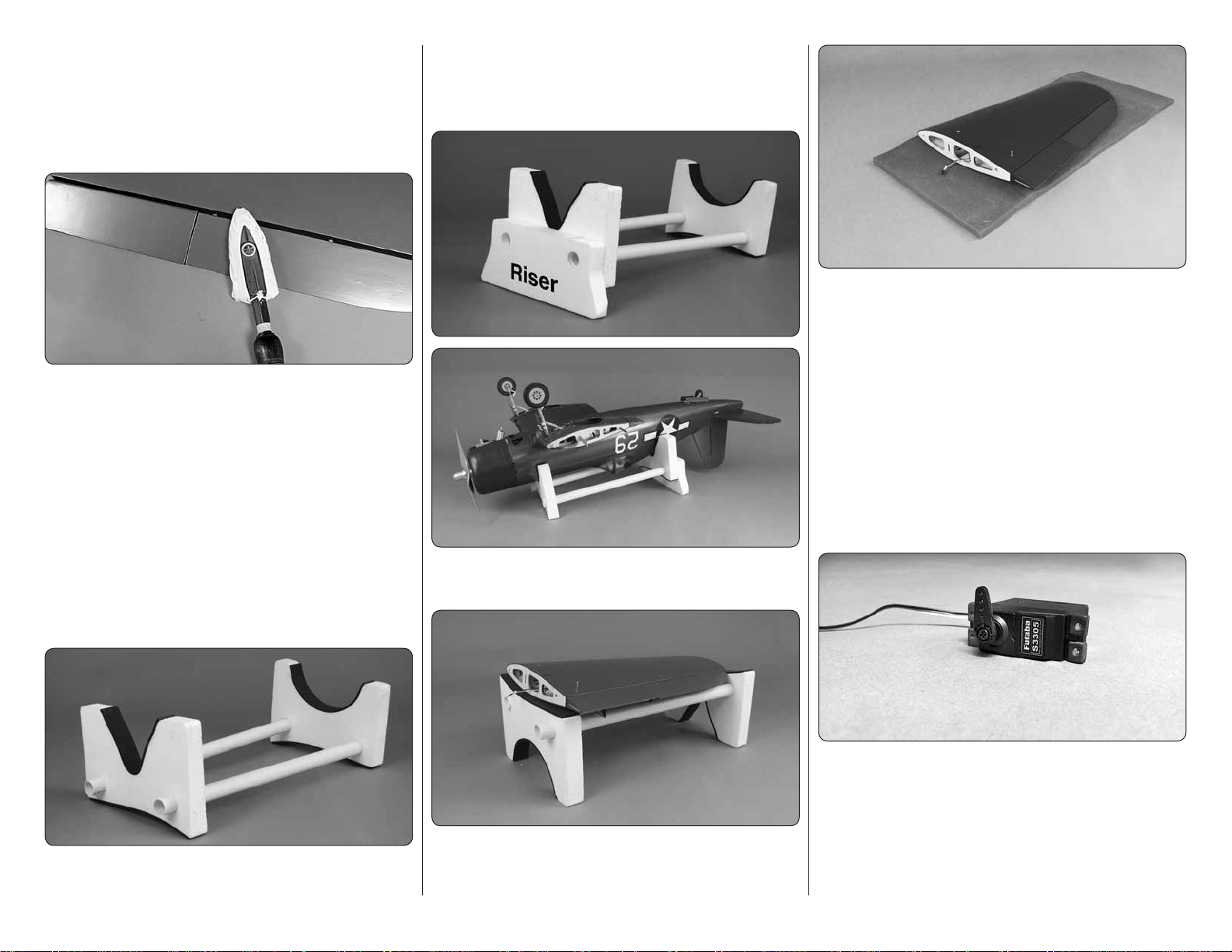
The foam stand is also a great aid when installing the
wing to the fuselage at the airfi eld. To assemble the
stand, slide the two plastic tubes into the foam cradles.
One side of the cradle fi ts the fuselage.
The foam pad can be used on your workbench to provide
cushioning for the components when working with them
on your workbench.
ASSEMBLE THE WING
Note: Throughout this instruction manual you will be
instructed to use screws to secure different parts. In
all cases, whenever a screw is threaded into wood
sheeting or wood blocks, w e recommend that you install
the screw and then remove it. Apply a drop of thin CA
glue into the hole to harden the threads. After the glue
has hardened, re-install the screw. Following this step
will insure that you have a solid thread for your screws.
When the riser is added it offers protection to the fi n/
rudder from the bench.
AIRPLANE STAND AND PROTECTIVE PAD
Your kit includes a foam stand and a protective pad to
help prevent “hangar rash” during the assembly process.
The other side of the cradle matches the contour of the
wing, allowing the cradle to be used for a wing holder.
6
1. Begin with your right wing panel fi rst so your
❏ ❏
assembly matches the photos in the manual. Cut three
arms from a servo horn, leaving a single servo arm.
The distance from the center of the arm to the outer
hole should be approximately 3/4" [19mm]. Center the
servo and install the arm as shown. Install the rubber
grommets and eyelets on the servo.
Page 7
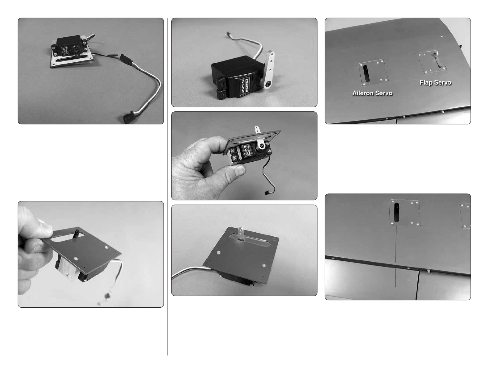
2. Remove the aileron servo cover from the
❏ ❏
bottom of the wing. Place your servo between the servo
mounting blocks located on the bottom of the cover. Drill
a 1/16" [1.6mm] hole through each of the servo mounting
holes into the hardwood block. Install the servo to the
servo cover with the screws included with your servo.
Attach a 6" [152mm] servo extension to the servo lead.
Secure the lead with heat shrink tubing, tape or some
other method to assure the leads stay connected.
3. On the other side of the servo cover drill a 1/6"
❏ ❏
[1.6mm] hole through the servo cover and into each
of the hardwood blocks. Secure the block to the cover
with a #2 3/8" [9.5mm] wood screw in each of the
holes you drilled.
4. With another servo, center the servo and install
❏ ❏
a 1" [25mm] servo arm (FUTM2120 for Futaba servos).
Remove the fl ap servo cover from the wing and install
the servo using the same technique used for the aileron.
Be sure to install the #2 3/8" [9.5mm] wood screw in
each of the holes you drilled.
5. There is a string that goes through the wing and
❏ ❏
is attached to the root rib of the wing panel. If needed,
tie the aileron servo lead to the string and then pull the
lead through the wing. (Since you are passing the lead
through a very short distance in the wing you probably
do not need to use the string). Secure the aileron servo
cover with four #2 X 3/8" [9.5mm] screws and four #2
fl at washers.
6. Using a fi ne tip marker draw a line from the
❏ ❏
servo arm toward the aileron. Under the skin of the
aileron there is a plywood plate. Place a large black
nylon control horn onto the aileron so that the horn is
in line with the line you have drawn. Holes in the horn
should be positioned over the hinge line.
7
Page 8
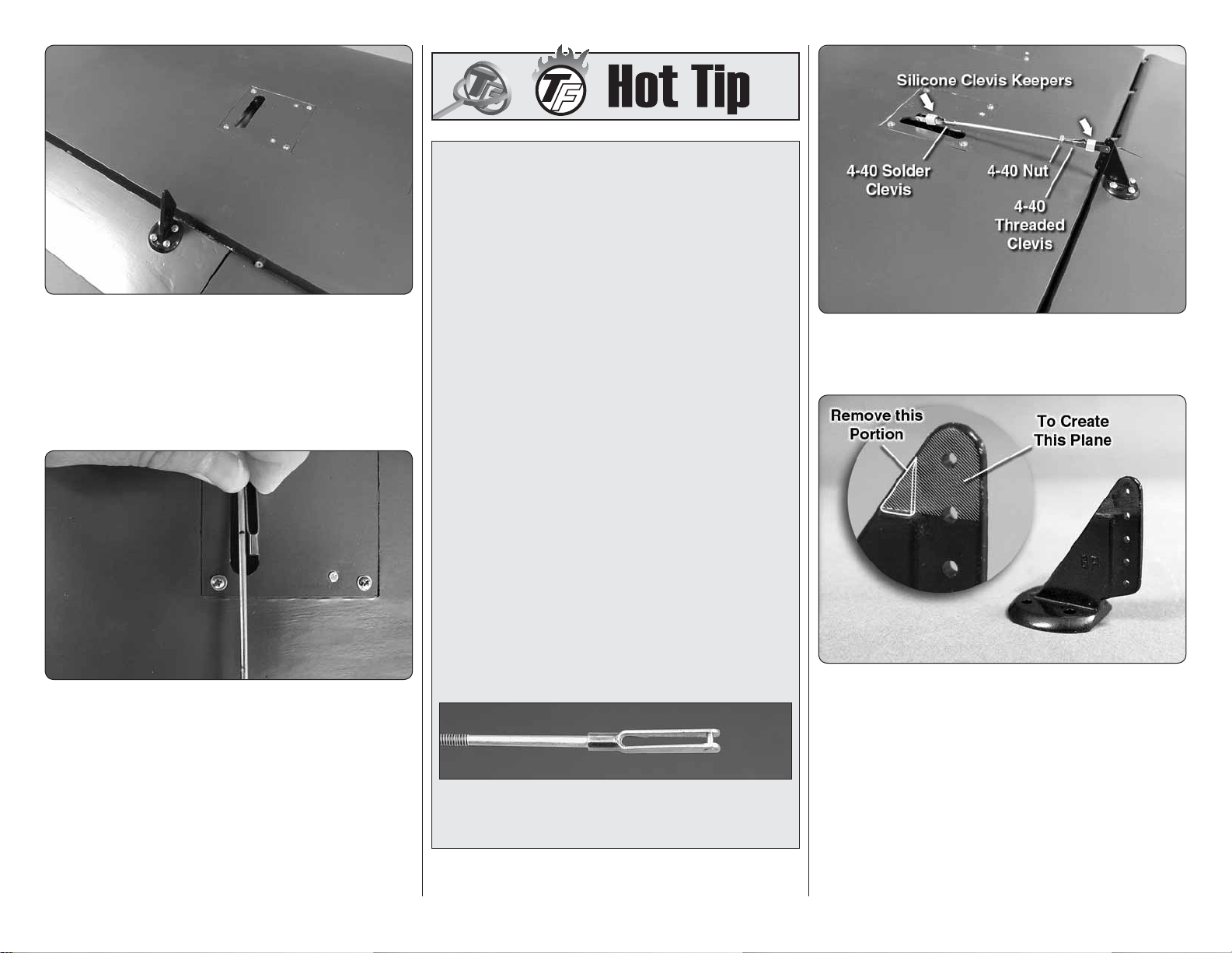
7. Drill a 3/32" [2.4mm] hole through each of the
❏ ❏
mounting holes in the control horn, drilling into the
plywood plate. Do not drill through the top of the aileron.
Secure the control horn with four #4 1/2" [13mm]
screws. (Be sure you install the screw and then remove it.
Apply a drop of thin CA glue into the holes as instructed
at the beginning of this section of the manual).
8. On the threaded end of a 4-40 5-3/4" [146mm]
❏ ❏
wire install a 4-40 nut, silicone clevis keeper and
threaded clevis. Install the clevis into the second hole
from the end of the clevis. Install a 4-40 solder clevis
into the outer hole of the servo horn. Be sure the servo
and the aileron are centered. Make a mark on the wire
where it passes through the solder clevis. Cut the wire
on that mark. Remove the clevises and wire from the
control horn and servo arm. Solder the solder clevis to
the wire. If you are not familiar with solder techniques
use the method in the “Hot Tip” that follows this step.
HOW T O SOLDER
1. Use denatured alcohol or other solvent to
thoroughly clean the pushrod. Roughen the end of
the pushrod with coarse sandpaper where it is to be
soldered.
2. Apply a few drops of soldering fl ux to the end of
the pushrod, then use a soldering iron or a torch
to heat it. “Tin” the heated area with silver solder
by applying the solder to the end. The heat of the
pushrod should melt the solder – not the fl ame of
the torch or soldering iron – thus allowing the solder
to fl ow. The end of the wire should be coated with
solder all the way around.
3. Place the clevis on the end of the pushrod. Add
another drop of fl ux, then heat and add solder. The
same as before, the heat of the parts being soldered
should melt the solder, thus allowing it to fl ow. Allow
the joint to cool naturally without disturbing. Avoid
excess blobs, but make certain the joint is thoroughly
soldered. The solder should be shiny, not rough. If
necessary, reheat the joint and allow to cool.
4. Immediately after the solder has solidifi ed, but
while it is still hot, use a cloth to quickly wipe off
the fl ux before it hardens. Important: After the joint
cools, coat the joint with oil to prevent rust. Note: Do
not use the acid fl ux that comes with silver solder for
electrical soldering.
This is what a properly soldered clevis looks like
– shiny solder with good flow, no blobs and flux
removed.
8
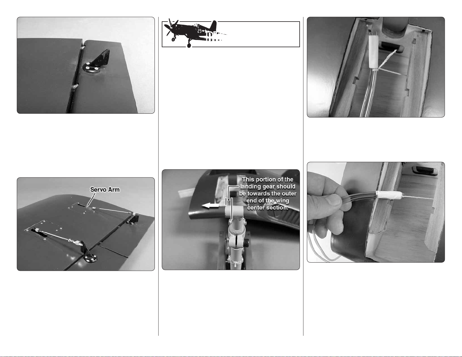
9. Install the pushrod assembly to the servo arm
❏ ❏
and the clevis. Be sure to install a silicone clevis keeper
onto both clevises.
10. The photo above shows how the clevis has
❏ ❏
been modifi ed for installation in the next step. Use a
sanding bar or moto-tool with a sanding drum to remove
the material on the top 1/4" [6mm] of the clevis. The
clevis needs to be even in this area on both sides of
the clevis.
Page 9
Did You Know?…Did You Know?…
Early in the Pacifi c W ar , US Navy and Marine Corps
fi ghter pilots found themselves outclassed by the
agile and well-armed Japanese A6M Zero, but even
then work was underway to pro vide them with better
aircraft. One of those better air craft was the Vought
“F4U Corsair”, a rugged, powerful, and somewhat
unforgiving aircraft that featured a distinctive
inverted gull wing.
11. Install another control horn on the fl ap using
❏ ❏
the same technique used for the aileron. NOTE: The
fl ap control horn should be installed as shown here.
This gives a better mechanical advantage to the servo
for operating the fl aps.
12. Install the fl ap servo cover, securing it with four
❏ ❏
#2 3/8" [9.5mm] screws and #2 fl at washers
13. Position the fl ap to its fully retracted position
❏ ❏
and position the servo arm so that it is rotated back
towards the trailing edge of the wing. Make the fl ap
pushrod wire assembly using the same techniques used
for the ailerons in step #8. When you have completed
the pushrod assembly install the pushrod to the fl ap
control horn and the servo arm as in step 9.
INSTALL THE MAIN LANDING GEAR
Note: Just a reminder, whenever a screw is threaded
into wood sheeting or wood blocks w e recommend that
you install the screw and then remov e it. Apply a drop of
thin CA glue into the hole to harden the threads. After
the glue has hardened, re-install the screw.
1. Before beginning your installation you need to
❏ ❏
determine which of the landing gear is the right and
left. When installing the landing gear the longer half of
the landing gear foot should be towards the outer end
of the wing center section. Start with the installation of
the left landing gear (as viewed from the top rear) so
your work matches the photos shown here.
2. Cut two pieces of differently colored air line 30"
❏ ❏
[762mm] in length. Using masking tape, tightly tape
the two lines together. Taped inside the wing is a string.
Securely tie the string around the end of one of the air
lines below the masking tape.
3. Pull the string forward toward the end of the two
❏ ❏
air lines. Tape the string to the air line, keeping the string
as close to the center of the two air lines as possible. It
is a tight fi t to pull the air line through the wing so the
closer you can keep the string to the center of the two
air lines the easier it will be to pull them through the wing.
14. Repeat steps 1-13 for the left wing panel.
❏
9
Page 10
4. On the top of the wing center section there is
❏ ❏
a hole located at the front of the wing where you will
fi nd a string attached. Gently pull the string that the
air line is attached to, pulling the air line out of the hole.
Do not pull too hard causing the string to break! If
the lines get caught on a rib while pulling the air line
through the wing, pull the air line and string back out,
re-position where the string is taped to the lines and
try pulling the line through again. Should you break the
string it will be very diffi cult to feed a new string into the
wing. Tape the air line to the top of the wing to prevent
the lines from falling back into the wing.
5. Repeat this for the left side of the wing.
❏
6. Install each of the two air lines onto the air in /
❏ ❏
out ports on the air cylinder. Make note of which color
air line you install on each so that you install them the
same way when installing the remaining landing gear.
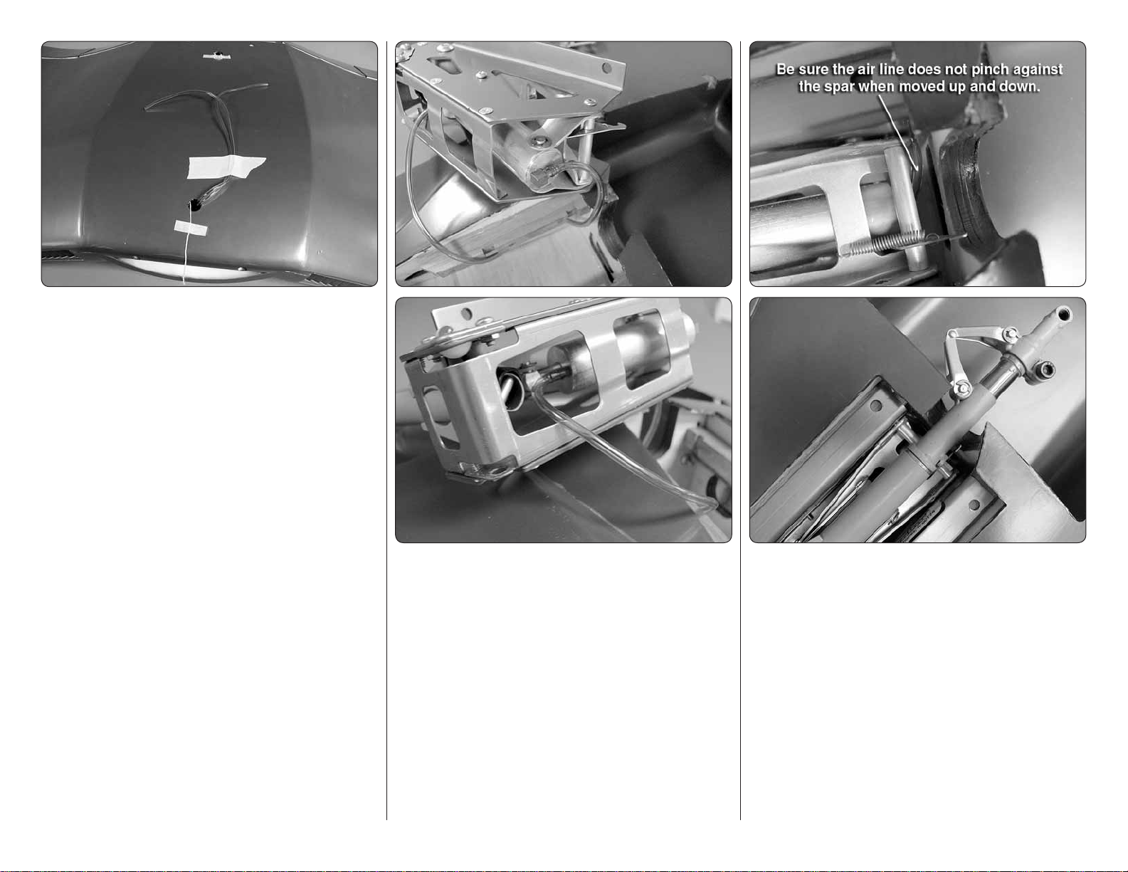
7. Place the landing gear on the landing gear rails.
❏ ❏
Manually move the landing gear leg up and down. You
will see that the air cylinder moves forward and aft when
the leg moves. The landing gear is properly positioned
on the rails when you can move the landing gear leg
up and down without the air line being pinched at the
back of the cylinder against the wing spar.
8. Double check your placement of the landing
❏ ❏
gear on the rails, then use a 1/16" [1.6mm] drill bit to
drill a pilot hole through each of the mounting holes in
the landing gear mounting plates and into the hardwood
mounting rails.
10
Page 11
9. Using the pilot holes you drilled as your guide,
❏ ❏
drill a 7/64" [2.8mm] hole through each of the pilot holes
and into the hardwood rails. Secure the landing gear to
the mounting rails with four #6 1/2" [13 mm] screws.
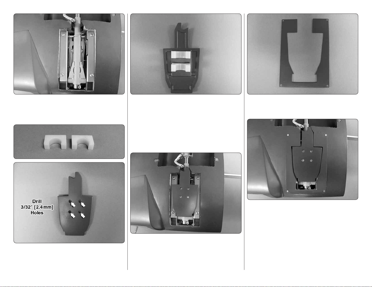
11. Position the nylon landing gear door mounts
❏ ❏
on the back of the landing gear door, centering the
mounts on the door and the holes you drilled. Now that
you know where to place the mounts, tack glue the
mounts to the door with CA glue. Once the glue has
hardened turn the door over and drill a 1/16" [1.6mm]
hole through each of the holes you drilled and into the
nylon mounts. Attach the mounts to the door with four
#2 3/8" [9.5 mm] wood screws.
13. Locate the door cover. Drill a 3/32" [2.4mm]
❏ ❏
hole in each corner of the cover. Keep the holes as
close to the corners as possible.
14. Place the door cover over the opening for the
❏ ❏
landing gear. Drill 1/16" [1.6mm] holes through the holes
in the door cover and into the wing. Secure the cover
with four #2 3/8" [9.5 mm] wood screws. Be sure to
apply some thin CA into the holes to harden the threads.
10. Locate two of the nylon landing gear door
❏ ❏
mounts and the right landing gear door. Drill a 3/32"
[2.4mm] hole centered through each of the four molded
recesses in the door.
12. Snap the doors onto the leg of the landing
❏ ❏
gear. To adjust the fi nal position of the doors slide the
door up or down on the landing gear.
11
Page 12
You now have a decision to make in completing the
installation of the landing gear. We have provided scale
inner doors for the more scale minded modeler. Because
of the costs and extra skill required for this we have
not engineered the installation of the doors as part of
the assembly process. We have provided the doors so
if you choose to have functional doors you will have
something to work with. If you will not be installing the
doors move on to step 15.
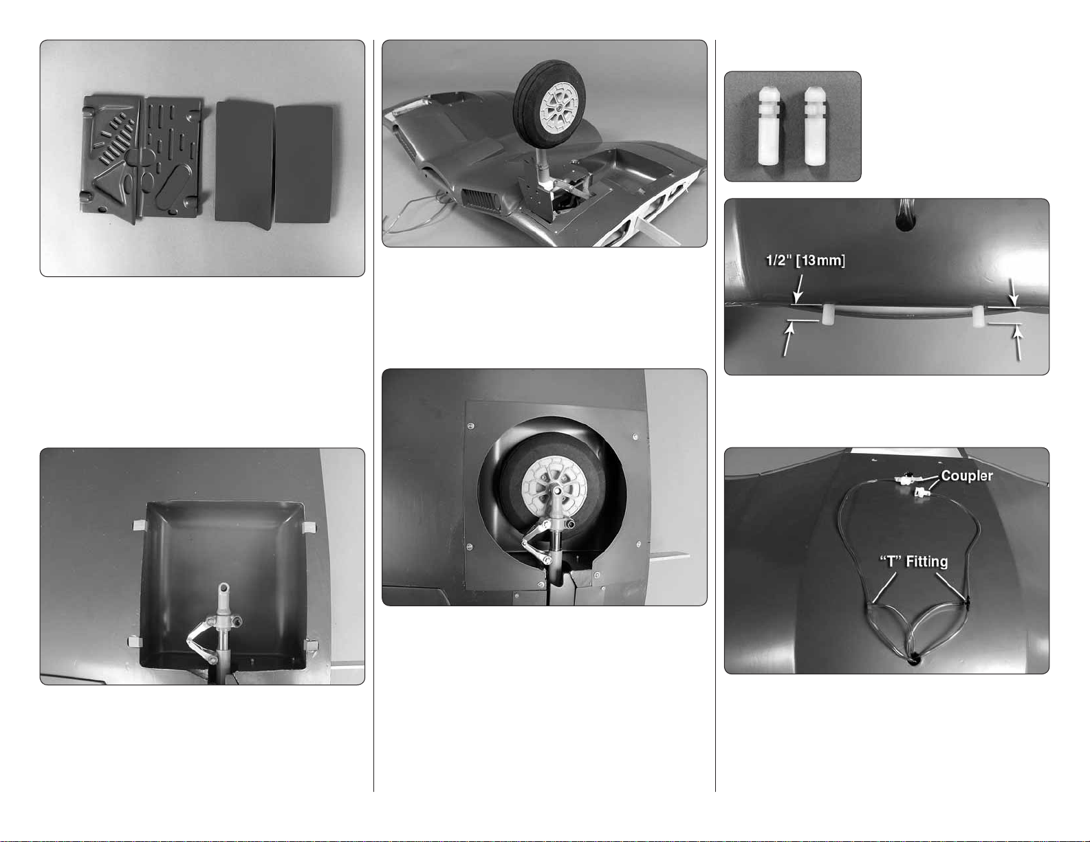
16. Using the axle and hardware that came with
❏ ❏
the retractable landing gear, install the wheel to the
landing gear. The center hub of the wheel may need
to be opened slightly. If your axle is a bit snug open the
wheel hub with a 1/4" [25mm] drill bit. Be sure you use
thread locker on the axle and axle nut.
FINAL WING ASSEMBL Y
1. Locate two nylon pins.
❏ ❏
Test fi t the pins into the holes
in the leading edge of the
wing. When you are satisfi ed
with the fi t, apply epoxy to the
ribbed end of the pins and into
the holes in the wing.
Insert the pins into the holes leaving approximately 1/2"
[13mm] of the pin extending from the leading edge of
the wing.
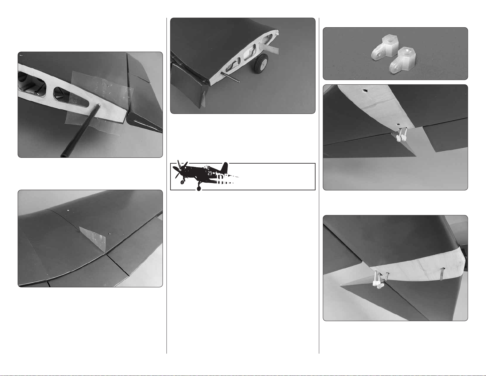
15. Locate four 3/8" 3/8" 1/4" wood blocks.
❏ ❏
Glue them fl ush with the surface of the wing over the
openings in the wheel well. (Do not be concerned about
the pre-drilled holes that you will cover . These holes are
for hinges if you would be installing doors). You may
need to slightly trim the block to get a good fi t.
17. Lower the landing gear so the wheel is in the
❏ ❏
wheel well. Place a wheel well cover over the opening
and center the cover over the wheel and the four wood
blocks you glued in place. Be sure the wheel can be
raised and lowered without touching the cover. Drill six
1/16" [1.6 mm] holes through the cover and into the four
wood blocks and the wing at the location shown in the
photo. Secure the cover to the wing with six #2 3/8"
[9.5 mm] screws and #2 fl at washers.
18. Repeat steps 6 – 17 for the left landing gear.
❏
12
2. Cut the four air lines approximately 3" [76mm]
❏ ❏
outside of the hole in the wing. Install a “T” fi tting to the
two pink colored lines and a “T” fi tting to the two purple
lines. Install a pink and purple extension of approximately
6" [152mm] onto each of the “T’s” and then install an
air line coupler to the end of each line.
Page 13
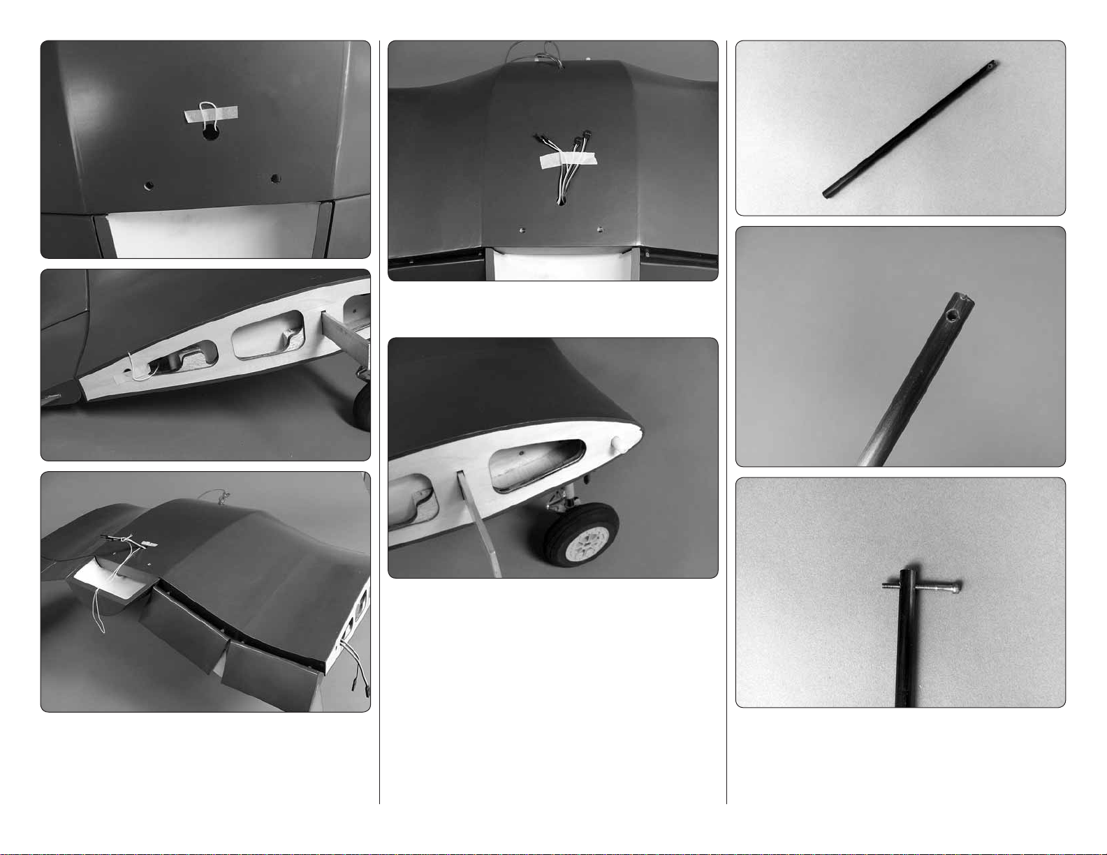
4. Tape the leads to the wing to prevent them from
❏ ❏
dropping back into the wing.
5. Glue a nylon pin into the forward hole in the root
❏ ❏
rib of the wing center section. The pin should extend
approximately 1/2" [13 mm] from the rib. Do this on both
sides of the wing center section.
3. On the top center rear of the wing is a hole with
❏ ❏
a string taped. The opposite end of the string is taped
to the root rib of the wing. Tie two 24" [610mm] servo
extensions to the string and pull them through the wing.
Do this for both the left and right side of the wing.
13
6. Locate one of the carbon fi ber tubes with a
❏ ❏
nylon insert and a pre-drilled hole in one end. The
hole is pre-tapped. Insert and then remove a 4-40 1"
[25 mm] socket head cap screw into the hole to check
that the tapped hole and bolt fi t well.
Page 14
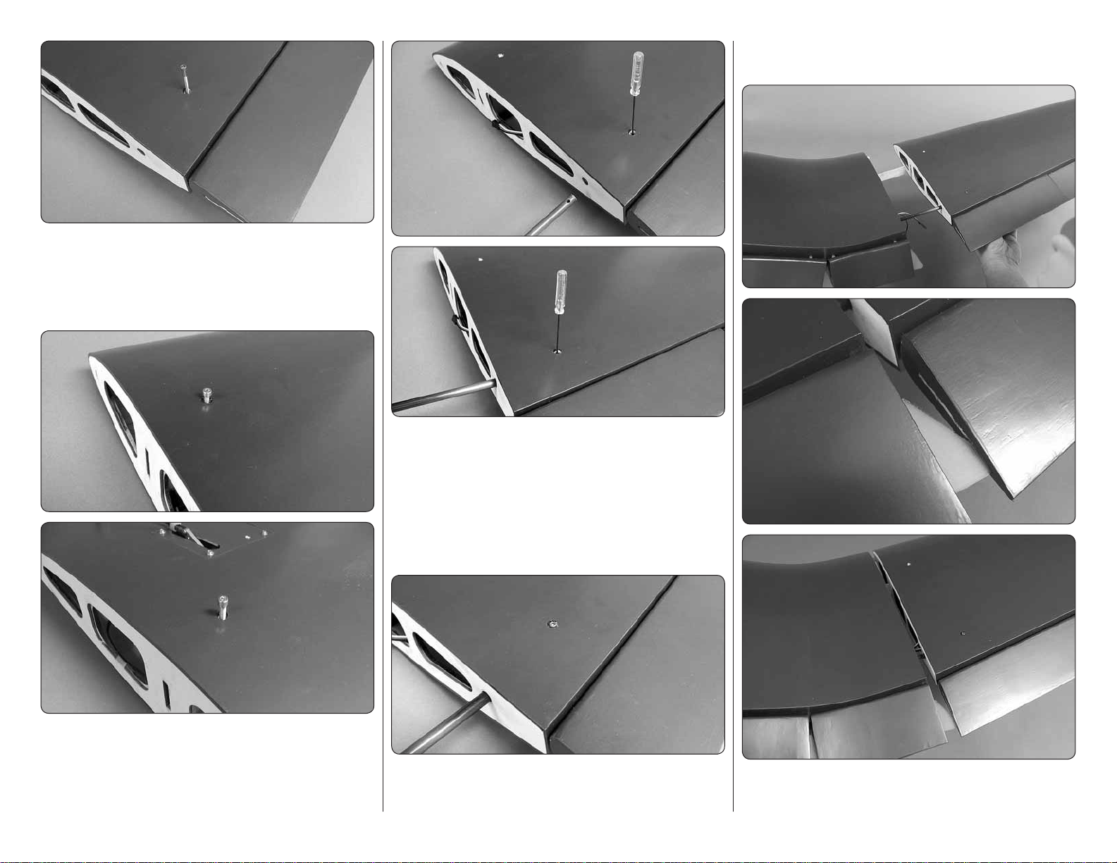
7. On the top of the wing towards the trailing edge
❏ ❏
of the wing is a pre-drilled and tapped hole. Insert and
then remove a 4- 40 1" [25 mm] socket head cap
screw into the hole to check that the tapped hole and
bolt fi t well.
9. In the rear hole in the top of the wing, insert a
❏ ❏
ball wrench that is small enough to fi t through the hole.
A 2-56 wrench works well for this. Insert the end of the
carbon tube with the tapped hole into the hole, sliding it
in until it contacts the wrench. Raise the wrench a little
until the tube is able to be inserted further into the wing.
Use the wrench to locate and align the hole in the tube
with the hole in the wing.
aligned properly the bolt will thread through smoothly.
Leave the bolt in place for the next couple of steps.
8. On the top and bottom of the wing near the
❏ ❏
center of the wing are two pre-drilled and tapped holes.
Insert and then remove a 4-40 3/4" [19 mm] socket
head cap screw into each hole to check that the tapped
hole and bolt fi t well.
10. Thread the 4- 40 1" [25 mm] socket head cap
❏ ❏
screw into the wing and through the hole in the tube. Be
sure that you do not force the bolt. When the holes are
14
11. Test fi t the right wing panel onto the wing
❏ ❏
center section. As you slide the wing together be sure
Page 15
to align the fl ap on the outer wing panel with the fl ap
tab extending from the fl ap in the wing center section.
Once you are satisfi ed with the fi t of the wing and center
section remove the outer wing panel.
12. Cut a 3" 3" [76 mm 76 mm] square from
❏ ❏
a plastic bag. Make a small hole in the center of the
plastic and slide it over the carbon tube.
14. Once the glue has hardened remove both of
❏ ❏
the wing bolts. Then, slide the outer wing panel from
the wing center section.
15. Repeat steps 1-14 for the left wing panel.
❏
Did You Know?…Did You Know?…
INSTALL THE RUDDER & STAB / ELEVATOR
13. Apply a light coating of epoxy to the carbon
❏ ❏
tube. Install the outer wing to the wing center section.
As you slide the tube into the wing center section clear
away any excess epoxy. Repeat this until the wing panels
are pushed tightly together. Once the wings are together
tighten the 4-40 3/4" [19 mm] socket head cap screw
in the forward hole in the top of the wing to keep the
wings securely together while the epoxy hardens.
According to old stories, the Japanese learned to
call the F4U “Whistling Death” because of the highpitched sound it made, though such a melodramatic
name sounds suspiciously like an invention of
American publicists. It was also known as the
“Bent Wing Bird”, though on the other side of the
coin this name sounds more like something out
of company press releases. Whatever the enemy
or the aircrew actually called the F4U, it was still a
machine to be reckoned with, one way or another.
Many pilots became aces in the Corsair, but even
its most passionate advocates admitted that it was
a handful.
ASSEMBLE THE FUSELAGE
Note: Just a reminder, whenever a screw is threaded
into wood sheeting or wood blocks w e recommend that
you install the screw and then remov e it. Apply a drop of
thin CA glue into the hole to harden the threads. After
the glue has hardened, re-install the screw.
15
1. Install the threaded nylon control horn onto the
❏
threaded end of the elevator control wires.
2. This next step can be a bit tedious so plan to take
❏
your time. Install a 6 -32 1-1/2" [38mm] socket head
cap screw into the two holes in the fi berglass fairing
on top of the elevator passing through and exiting from
Page 16

the bottom of the stabilizer. This can be a bit diffi cult.
We found it was easiest to do this with a forceps by
grabbing the head of the bolt and feeding it down into
the holes. You can also use a magnetized ball wrench
or by placing a small amount of clay into the head of
the bolt and inserting the ball wrench into it. If while
inserting the bolt it should fall into the fi berglass fairing
you can remove it through the hole in front of the fairing.
Once both bolts are in place through the stab set the
stab aside, making sure you do not dislodge the bolts.
3. Next you are going to test fi t the stab to the stab
❏
saddle to get a feel for the installation of the stab before
applying epoxy. The back of the fuselage has two blind
nuts installed in a plywood plate. The bolts in the stab will
screw into these. Before fi tting the stab to the fuselage
be sure you have a ball wrench that is not magnetized.
Using a magnetized ball wrench will likely pull the bolts
out of the stab. Place the stab onto the stab saddle.
Center the stab on the stab saddle. Then, use the ball
wrench to fi nd the head of the bolt and thread the bolt
into the blind nuts. Now that you have a feel for the
installation process remove the stab, leaving the bolts
in place in the stab, and set the stab to the side.
4. Apply 30 minute epoxy to the stab saddle. Install
❏
the stab onto the stab saddle and tighten the bolts
securing the stab to the fuselage. Clean any excess
epoxy from the fuselage and stab with a paper towel
and alcohol.
5. Apply a couple of
❏
drops of oil or Vaseline
to the center of three
hinge point hinges.
This will prevent glue
from getting into the
hinge. Apply epoxy to
one end of each hinge
and insert them into the
rudder. Once the glue
has hardened move on
to the next step.
16
6. Apply epoxy into the small hole in the bottom of
❏
the rudder and onto the three hinges. Insert the rudder
into the fi n. Clean any excess epoxy away with a paper
towel and alcohol. Allow the epoxy to harden.
Page 17

7. Prepare two 48"
❏
[1220mm] threaded
pushrod wires by
installing a 4-40
nut, 4-40 threaded
clevis (20 turns)
and silicone clevis
keeper.
10. Assemble another 48" [1220mm] pushrod wire,
❏
4-40 nut, 4-40 threaded clevis and silicone clevis keeper.
Insert the wire from the back of the fuselage into the
nylon tube that aligns with the rudder control wire. Attach
the clevis to the rudder control horn.
pull wire, (2) crimp connectors, steering arm, (3) 1/8"
[3.2mm] wheel collars and (4) set screws..
8. From the back of the fuselage insert the two pushrod
❏
wires into the nylon tubes located in the fuselage.
9. Attach the clevises to the elevator control horns,
❏
and secure them with silicone clevis keepers.
INST ALL THE T AIL WHEEL ASSSEMBL Y
You now need to make a choice of the tail wheel that you
will install. The kit includes a fi xed tail wheel and we offer
the option to install a Robart Fork Pneumatic Retract
Tail Wheel (ROBQ2230). If you will be installing the
optional retractable tail wheel, skip ahead to “Installing
the Retractable Tail Wheel”. If installing the fi xed tail
wheel continue with the next step.
INST ALLING THE FIXED T AIL WHEEL
1. Locate the components of the tail wheel assembly.
❏
The tail wheel bracket, tail wheel, tail wheel wire, pull-
2. Assemble the tail wheel assembly. As part of the
❏
process be sure to apply a couple of drops of thread
locker to each of the set screws. We recommend that you
disassemble the two screws and nuts from the bracket.
Re-assemble them, applying thread locker.
3. Align the steering arm with the tail wheel wire. Then,
❏
using a small fl at fi le or rotary tool, make a fl at spot on
the tail wheel wire where the steering arm set screw
makes contact with the tail wheel wire and where the
outer wheel collar set screw makes contact.
17
Page 18

4. Use wire cutters to cut the supplied braided cable
❏
into two equal lengths. Slide a crimp connector over one
end of the cables, then guide the end of the cable back
through the hole in the steering arm and back through
the crimp connector.
5. Wrap the cable back around the crimp connector
❏
and back through the crimp connector.
6. Use pliers to pull the cable from the fi rst loop to
❏
reduce the size of the second loop. Squeeze the crimp
connector with a pliers to keep the wire secure. Cut off
the excess wire from the end.
Do this for both sides of the steering arm.
7. Slide the wires into the plastic tubes in the back
❏
of the fuselage.
8. Place the tail wheel bracket onto the wood rails.
❏
Drill a 3/32" [2.4 mm] hole through each of the mounting
holes. If your drill bit is not long enough to reach the
rail nearest the top of the fuselage, use medium CA
to temporarily glue a 3/32" [2.4 mm] drill bit in a 1/8"
[3.2 mm] brass tube. After drilling the holes, the drill
bit can be removed from the tube by heating the tube.
Secure the bracket with four #4 1/2" [13 mm] screws
and #4 washers.
18
Skip ahead to page 20, “INSTALL THE TAIL WHEEL
DOORS”.
Page 19

INST ALLING THE RETRACT ABLE T AIL
WHEEL
1. Remove the steering arm from the Robart
❏
retractable tail gear assembly (not included). File a fl at
spot near the top of the shaft for the set screw in the
steering arm. Mount the steering arm to the shaft with
a drop of threadlocker and the set screw. File another
fl at spot near the bottom of the shaft for one of the set
screws in the strut. Tighten both set screws with a drop
of threadlocker on each. Be certain the steering arm
and the axle in the strut remain parallel with each other.
Make adjustments to the fl at spots if necessary.
2. Insert an 0-80 ball link ball into the outer holes of
❏
the steering arm. Secure each ball with a 0-80 nut and
a drop of threadlocker.
3. Use wire cutters to cut the supplied braided cable
❏
into two equal lengths. Slide a crimp connector over
one end of the cables, then guide the end of the cable
back through.
4. Wrap the cable back around the crimp connector
❏
and back through the crimp connector.
5. Use pliers to pull the cable from the fi rst loop to
❏
reduce the size of the second loop.
6. Now pull on the long end of the cable to reduce
❏
the size of the fi rst loop. Slip the loop over one of the
ball link balls on the steering arm. Tighten the loop
until it is small enough to remain secure on the ball,
yet may still be pried off. Squeeze the crimp connector
with pliers. Connect the other cable to the other ball
link ball the same way.
7. Connect 40" [1016mm] of purple air line to the
❏
forward air fi tting and 40" [1016mm] of red air line to
the aft fi tting on the air cylinder. There is not enough
air line leftover from the main gear, so additional line
will have to be purchased separately (Robart #169
Pressure Tubing).
19
Page 20

8. Place the tail gear in the fuselage while
❏
simultaneously guiding the pull/pull cable through the
white plastic guide tubes. If installing the retractable tail
gear, also guide the air lines through the fuselage. Drill
four 3/32" [2.4mm] holes through the rails for mounting
the tail gear. If your drill bit is not long enough to reach
the rail nearest the top of the fuselage, use medium
CA to temporarily glue a 3/32" [2.4mm] drill bit in a 1/8"
[3.2mm] brass tube. After drilling the holes, the drill
bit can be removed from the tube by heating the tube.
no need for set screws in the wheel collars. They are
simply wheel spacers).
INST ALL THE T AIL WHEEL DOORS
(OPTIONAL)
We have provided tail wheel doors that will work with
either the fi xed landing gear or the retractable landing
gear. If you fl y from thick or tall grass you should consider
whether you wish to install them as the grass may catch
on the doors. If you choose not to install them skip
ahead to the next section, Install the Tail Cone.
1. Locate four nylon
❏
hinges and test fit
them into the holes in
the landing gear door.
The holes may be a
little tight depending
on the amount of
fiberglass flashing
near the holes. Use
a hobby knife to open
the hole as needed.
3. Remove the doors from the fuselage and remove
❏
the hinges from the doors. Apply a drop or two of oil to
the center of the hinge to prevent the glue from getting
in the hinge.
4. Using 30 minute epoxy, glue the hinges to the doors
❏
and the hinges to the fuselage. Position the doors on the
hinges until the doors can be opened and closed without
any restriction. Clean excess epoxy from the doors and
fuselage with a paper towel and alcohol. Allow the glue
to fully harden before moving on to the next step.
9. Mount the tail gear in the fuselage with four #4
❏
1/2" [12.7mm] sheet metal screws and #4 washers.
Enlarge the center hole through the 2" [51mm] tail wheel
with a 3/16" [4.8mm] drill to fi t the axle. Remove the
axle screws. Then, slide a 3/16" [4.8mm] wheel collar
onto the axle followed by the wheel and another wheel
collar. Apply thread locker to the axle screws and then
re-install the screws to secure the axle. (Note: There is
2. Test fi t the doors and hinges to the fuselage.
❏
Position the doors and hinges so the doors are equally
spaced. Open and close the doors, making sure they
open without any restriction. Take note of the position
of the hinges so when you glue them into place you will
have a good idea of the hinge position.
20
5. Completely open the doors and fully extend the
❏
tail wheel. Locate the 3" [76mm] spring. Insert it through
the second hole from the end of the tail wheel bracket.
Make a mark on the doors in line with spring. Remove
the spring.
Page 21

6. Locate two metal “L” brackets. Center them on the
❏
marks and glue them to the door with epoxy. Before
gluing them to door, roughen the door where they will
be glued and clean the “L” brackets with alcohol.
8. Make sure your doors open and close smoothly.
❏
Add a drop of oil to the hinges if they bind. The spring
pulls the doors closed when the tail wheel is retracted
and keeps them open when the gear is extended.
INST ALL THE T AIL CONE
1. Locate the fi berglass
❏
tail cone. Test fi t it to the back
of the fuselage.
forward to the front of the fuselage 1" [25mm]. Make a
mark with a fi ne point felt tip pen. Do this on both sides
of the fuselage.
3. Place the tail cone in place on the back of the
❏
fuselage. Using your reference marks, make a mark
on the tail cone where to drill the mounting holes. Drill
a 1/16" [1.6mm] hole through the tail cone into the
mounting blocks. Secure the tail cone with two #2
3/8" screws and #2 fl at washers.
7. Pull 1/4" [6mm] of the spring from each end. Twist
❏
one end of the spring to the bracket on one of the doors.
Push the opposite end of the spring through the second
hole in the tail wheel bracket and twist the end of the
wire through the bracket on the other door.
2. You will fi nd two mounting blocks located on the
❏
back of the fuselage. The fi berglass tail cone is secured
to these blocks. Measure from the center of the block
21
Did You Know?…Did You Know?…
The most prominent gang of Marine Corsair pilots
was squadron VMF-214, led by Major (later Colonel)
Greg “Pappy” Boyington. Boyington was a rowdy,
combative, tough, hard-drinking Marine who
had fl own Curtiss P-40s with Claire Chennault’s
American Volunteer Group (AVG) or “Flying Tigers”
in China and scored two kills. “Boyington’ s Bastards”
or “Black Sheep” racked up large scores against
the Japanese in the South Pacifi c, with Boyington
claiming a total of 28 kills during his combat career ,
22 of them in the F4U. He was shot down and captured
by the Japanese on 3 January 1944 and spent the
rest of the war in a prison camp. The Japanese
did not announce his capture and Boyington was
presumed killed in action. He would get the Medal
of Honor after his release from captivity at the end
of the war.
Page 22

INSTALL THE ELEVATOR AND RUDDER
SERVOS
Note: Just a reminder, whenever a screw is threaded
into wood sheeting or wood blocks w e recommend that
you install the screw and then remov e it. Apply a drop of
thin CA glue into the hole to harden the threads. After
the glue has hardened, re-install the screw.
1. From one of the four arm servo arms, cut three
❏
arms off leaving a single servo arm. Center the servo.
Then, install the servo horn to the servo.
2. Using the hardware that came with your servo,
❏
install a servo into the opening in line with the elevator.
Be sure the servo is centered and the elevator is
centered. Make a mark on the pushrod wire where
you will cut the pushrod to fi t into the clevis.
4. Cut the wire on the mark you made. Solder the
❏
wire to the solder clevis using the technique described
in the “Hot Tip” on page 8. After the solder has cured
install a silicone clevis keeper over the clevis and install
the clevis into the outer hole of the servo arm.
5. Install a servo for the other half of the elevator
❏
using the same technique used on the elevator servo
you just installed.
6. From one of the four arm servo arms, cut two arms
❏
off leaving a double servo arm. Center the servo. Then,
install the servo horn on the servo. Using the hardware
that came with your servo, install the servo as shown.
Feed the pull-pull wires from the tail wheel through the
opening in the bulk head.
3. Install a 4-40 solder clevis into the outer hole of
❏
the servo arm.
22
Page 23

7. Locate two 2-56 threaded clevises, crimp
❏
connectors, silicone clevis connectors, 2-56 nuts and
2-56 threaded couplers. Thread a 2-56 nut and clevis
onto the threaded coupler as well as the silicone clevis
keeper. Be sure to apply a couple of drops of thread
locker to the coupler and nut.
9. This is how the servo installation should look. Make
❏
sure you have put all of the clevis retainers in place and
applied thread locker to the nuts.
INSTALL THE AIR CONTROL SYSTEM
IMPORTANT: The next step instructs you on the
installation of the air control valve servo. You will be
instructed to mount it on the right side of the fuselage.
It is mounted on the right side because our engine
installation requires the throttle servo to be on the left
side of the fuselage. Take a look at your engine and
determine which side the throttle servo needs to be
on. If you need to mount the throttle servo on the right
side you can follow the installation instructions for the
air control valve servo but install it on the left side.
servo. From the servo horn with the shortest set of
arms, cut away the arms leaving a single servo arm.
Enlarge the outer hole in the servo arm with a 3/32"
[2.4mm] drill bit.
2. Locate the plywood mounting bracket for the air
❏
control valve and two 1/4" 1/4" 3/4" [6 mm 6 mm
19 mm] hardwood blocks. Glue the blocks onto both
sides of the bracket.
8. Slide one of the crimp connectors onto one of the
❏
tail wheel pull-pull wires and then insert the wire through
the bottom hole in the threaded coupler. Attach the clevis
to the control horn. Repeat this with the remaining clevis
and crimp connector. Center the servo and the tail wheel.
Use the same technique you used when you secured
the pull-pull wires to the tail wheel, pulling the wires
tight before crimping the crimp connector with a plier.
1. On the right side of the fuselage install the servo
❏
that will operate the air control valve for the retractable
landing gear using the hardware that came with the
23
3. Install an 0-80 ball and nut into the hole in the
❏
end of the air control valve. Be sure to apply a drop of
thread locker to the threads.
4. Secure the air
❏
control valve to the
mounting bracket. Be
sure to use a couple of
drops of thread locker
on the nut.
Page 24

5. From a 2-56 6" [152mm] wire pushrod, cut off
❏
a portion of the threaded end of the wire leaving 1/2"
[13 mm] of threads on the wire. Install a nylon ball link
onto the threaded end of the wire.
6. Snap the ball link onto the ball on the end of the
❏
air control valve. Position the plywood mounting bracket
on the plywood former so that the pushrod wire is in line
with the outer hole in the servo arm. The wire should rest
on the underside of the servo arm. Glue the plywood
mounting bracket to the former.
mark on the wire where it passes under the hole in the
end of the servo arm. Make a 90 degree bend in the
wire on the mark. Cut off the excess wire 3/8" [9.5mm]
above the bend. Install the wire into the servo arm and
secure it with a nylon Faslink.
9. Locate the
❏
instrument panel and
temporarily install it into
the front of the cockpit.
Hold it in place and then slide the air tank into position
in the support holes. You will see that the air tank makes
contact with the back of the cockpit. Glue the air tank to
the support formers with silicone or Shoe Goo,™ leaving
about 1/8" [3.2mm] of clearance between the back of
the instrument panel and the bottom of the air tank.
Remove the instrument panel and allow the glue to dry.
7. Push the air control arm into the valve housing and
❏
rotate the servo arm forward towards the valve. Make a
8. Install the air tank into the hole under the servo tray.
❏
24
10. On both the left and right side of the fuselage there
❏
is a hole that is sized to fi t the air fi ll valve. Determine
Page 25

on which side of the fuselage you would like the valve
to be located and then open up the hole with a hobby
knife or rotary tool.
11. Install the fi ll valve into the side of the fuselage,
❏
securing it with the nut. Hint: It is common to have
the nut compress into the balsa wood over a period of
time. This can cause the fi ll valve to spin loose. Find a
washer that will fi t over the threads of the fi ll valve and
then tighten the nut as much as possible, compressing
the balsa wood. Do this a couple of times to compress
the balsa wood as much as possible. Apply a couple
of drops of thread locker and then tighten the nut to
the fuselage side.
12. Mark where the end of the valve gets close to
❏
the plywood former. Mark it and remove the area with
a hobby knife or a rotary tool.
13. Install a “T” fi tting in the air line between the air
❏
tank and the air valve. Install an air line to the “T” fi tting
and the air control valve. Install the air lines from the
air control valve to the air couplers. If you are unfamiliar
with the installation of the retractable landing gear air
line system, please refer to the instructions included
with the air control kit.
Did You Know?…Did You Know?…
After working out the worst bugs, the Navy fi nally
embraced the Corsair as the most capable fi ghter
and fi ghter-bomber in its in ventory , superior to the
Grumman F6F-3 Hellcat. By early 1944, the Navy
was making good use of the Corsair . The fi rst Navy
F4U squadron, VF-17 “Jolly Rogers” AKA “Skull &
Crossbones”, pr oduced 12 aces, the most pr ominent
being Lieutenant Ira Kepford, with 19 kills.
INSTALL THE ENGINE, THROTTLE SERVO
AND CHOKE SERVO
This manual outlines the installation of the DLE 55 engine.
There are many different 50cc engines on the market that
will perform well in the Corsair. If you will be installing
an engine other than the DLE 55 we recommend that
you take a few minutes and read through the engine
installation instructions. Installation of other brand
engines will be similar to the installation of the DLE 55
but you may need to modify the installation process for
your particular engine. We have designed the Corsair to
allow for the installation of engines with either a left side
mounted carburetor or a right side mounted carburetor.
For those who will be installing other engines, you may
need to make you own spacers or modifi cations to
mount the engine properly.
Note: Just a reminder, whenever a screw is threaded
into wood sheeting or wood blocks w e recommend that
you install the screw and then remov e it. Apply a drop of
thin CA glue into the hole to harden the threads. After
the glue has hardened, re-install the screw.
25
Page 26

1. Cut out the paper mounting template for the DLE
❏
55 located on page 47 of this manual. Tape the template
in place on the fi rewall, aligning the crossing lines with
the lines embossed onto the fi rewall.
2. Drill a 1/16" pilot hole through the paper templates.
❏
Remove the template from the fi rewall. Then drill 1/4"
[6mm] holes through each pilot hole. Before drilling the
holes check your particular brand of engine and the
hardware required for mounting the engine.
to use three of these spacers. The other pattern may
be used for other brands. Install your mounting bolts
for the stand-offs into the back side of the fi rewall. (We
also recommend the use of 3/4" [19mm] fender washers
with your mounting bolts). Install the plywood spacers
over the mounting bolts. Do not glue the spacers to
the fi rewall.
4. Hand tighten the stand-offs against the fi rewall.
❏
Do not do the fi nal installation at this time. In the next
few steps you will be removing the engine several times.
2-56 nut. Do the same to the choke arm if you will be
activating the choke with a servo. (Note: We will be
showing the installation of a servo and linkage for the
choke. We understand that many modelers have their
own way of activating the choke. If you do not wish to
use a servo to activate your choke , skip any references
to the choke installation in the instructions that follow).
6. Temporarily mount the engine to the stand-offs.
❏
(Be sure when installing the engine that you mount it
in the inverted position on the fuselage). Look at the
location of both the throttle and choke arms. You need
to make clearance for them in the spacers. Mark the
portion of the spacer that needs to be removed. Remove
the stand-offs and spacers, and then cut the area you
marked from both spacers.
3. We have included two pairs of four plywood spacers.
❏
The fi rewall has been positioned so that with or without
the use of spacers nearly every engine brand can be
properly spaced from the fi rewall. Locate the spacers
that match the hole pattern for the DLE 55. You will need
5. Install the servo arm extension onto the engine
❏
as shown in the engine assembly instructions. Install a
2-56 ball into the hole in the end of the throttle arm and
secure it with a couple of drops of thread locker and a
26
Page 27

7. Temporarily install the spacers and stand-offs onto
❏
the fi rewall. Mount the engine to the stand-offs.
8. Thread a nylon ball link onto one end of a 2-56
❏
1" [25mm] threaded wire. Snap the ball link onto the ball
on the throttle arm. Position the wire perpendicular to
the fi rewall and so it is in contact with the fi rewall. Make
a mark on the fi rewall with a felt tip pen. Remove the
engine from the stand-offs. Drill a 3/16" [4.8mm] hole
through the fi rewall on the mark.
27
9. Install the throttle servo into the servo tray using
❏
the hardware that came with the servo. Make a single
armed servo arm and install it on the servo. Note: We
have installed a plywood mini servo tray that can be
glued over the standard servo opening if you wish to
use a mini servo.
Page 28

10. Locate the 12-1/2" [320mm] long tube. Insert the
❏
tube into the hole you drilled in the fi rewall and guide it
into the fuselage. Align it with the servo arm. The tube
will run into a former. Mark the spot where it contacts
the former and drill a 3 /16" [4.8mm] hole in the former.
12. Thread the nylon ball link and threaded rod onto
❏
the end of the inner pushrod tube. Locate another 2-56
1" [25mm] threaded rod, a metal clevis, 2-56 nut and
silicone clevis keeper. Thread the nut and clevis onto
the wire and slide the clevis keeper onto the clevis.
cut off the excess pushrod from the inner pushrod tube.
Remove the clevis and wire from the servo arm. Cut
the inner pushrod tube and then screw the threaded
wire and clevis into the tube. Re-install the clevis into
the outer hole in the servo arm.
Steps 14-21 are only if you will be installing a choke
servo. If you will not be doing this, skip ahead to “Install
the Cowl”.
14. Cut the threaded
❏
portion of a nylon ball link in
half. Thread the cut ball link
onto a 2-56 1" [ 25 mm]
threaded rod. Snap the ball
link and wire onto the ball on the choke arm. Using the
same technique used for the throttle, mark where the
wire contacts the fi rewall. Drill a 3/16" [4.8mm] hole
through the fi rewall on the mark.
11. Slide the tube through the hole you made in
❏
the former, guiding it towards the throttle servo. Slide
the plywood pushrod support over the tube. Align the
tube with the outer hole in the servo arm. Then glue
the support to the former. Roughen the tube where it
passes through the fi rewall and formers before gluing
the tube in place.
13. Temporarily slide the inner pushrod tube into
❏
the outer pushrod and snap the nylon ball link onto
the ball on the throttle arm. Install the clevis into the
outer hole of the throttle servo arm. Using the length
of the threaded wire in the clevis, determine where to
28
15. Locate the plywood
❏
components of the choke
servo tray and two 1/4"
1/4" 7/8" [ 6mm 6 mm
21mm] hardwood
blocks. Glue the servo tray
together as shown.
16. Install the servo
❏
into the servo tray using
the hardware that came
with the servo.
Page 29

17. Drill two 1/16" [1.6mm] holes in the servo tray at
❏
the approximate locations shown.
19. Install the choke servo tray to the plywood former
❏
with two #2 3/8" [9.5 mm] screws and #2 fl at washers.
Be sure to position it so that the servo arm is in line
with the pushrod tube. Cut off the excess pushrod tube.
Roughen the tube where it passes through the fi rewall
and formers. Then, glue it in place.
the threaded wire in the clevis, determine where to cut
off the excess pushrod from the inner pushrod tube.
Remove the clevis and wire from the servo arm. Cut
the inner pushrod tube and then screw the threaded
wire and clevis into the tube. Re-install the clevis into
the outer hole in the servo arm.
INST ALL THE COWL
1. On the top of the fi rewall box make a line 1/4"
❏
[6mm] from the edge of the box.
18. Just as you did with outer pushrod tube for the
❏
throttle servo, install the 6" [160mm] outer pushrod tube
into the hole in the fi rewall, pushing it into the fuselage
until it contacts the former. Drill a 3/16" [4.8mm] hole
through the former. Pass the pushrod tube through this
hole into the fuselage.
20. Thread the nylon ball link and threaded rod onto
❏
the end of the inner pushrod tube. Locate another 2-56
1" [25mm] threaded rod, a metal clevis, 2-56 nut and
silicone clevis keeper. Thread the nut and clevis onto
the wire and slide the clevis keeper onto the clevis.
21. Temporarily slide the inner pushrod tube into
❏
the outer pushrod and snap the nylon ball link onto
the ball on the choke arm. Install the clevis into the
outer hole of the choke servo arm. Using the length of
29
2. Locate the two 3/4" 1" 1" [19 25 25] hardwood
❏
blocks. Place them on the top of the fi rewall box aligning
the edge of the blocks with the lines you drew. Trace
the outline of the blocks onto the front of the fuselage.
Page 30

hole with a drill press. If you do not have access to a
drill press, be sure you are careful to drill the hole as
straight as possible.
6. Install a 6-32 1-1/2" [38mm] socket head cap
❏
screw and #6 fl at washer into the front of the hardwood
block and thread a 6-32 blind nut onto the screw. Tighten
the screw, pulling the blind nut into the back of the block.
Do this for both blocks.
3. Cut the front of the fuselage on the lines you have
❏
drawn removing only the balsa wood. Cut the balsa,
making clearance for the blocks so that they can slide
into the fuselage. The blocks should slide back against
the plywood ring the balsa is glued to. When the blocks
are properly positioned, the distance from the front of the
block to the front of the fi rewall box will be approximately
7/16" [11.1mm]. Take a minute to mark each block so
that you know which are the right, left and bottom sides.
4. This step will be easiest if you have someone
❏
help you. With the two blocks in position (do not glue
them yet), place the cowl ring in place on the front of
the fuselage. The ring needs to be centered on the
fuselage. While holding the cowl ring in place have a
helper drill a 1/16" [1.6mm] pilot hole into the face of
the block, making sure it is centered in the hole in the
cowl ring. The hole does not have to be drilled very far
into the block, just deep enough to provide a starter
hole for the fi nal drilling you will do in the next step. Do
this for both blocks.
5. Remove the blocks and drill a hole through each of
❏
the blocks with a 5/32" [4mm] drill bit. It is important that
the hole be drilled straight. This will be best accomplished
if you can put the block in a drill press vise and drill the
30
7. Place the blocks back into position on the fi rewall
❏
block. Locate two 5/8" 3/4" 1" [16 mm 19mm
25mm] hardwood blocks. Place each of the blocks
against the fi rewall box as shown in the photo. The
block will rest against the side of the fi rewall box and
the balsa fuselage. The block will rest in place without
any glue for this step.
Page 31

8. Attach the cowl ring with two 6-32 1-1/2" [ 38 mm]
❏
socket head cap screws and #6 fl at washers into the
top two blocks.
9. Using the same procedure used on the top two
❏
blocks, drill a hole into each of the lower two blocks.
Once you have the starter hole in the block, remove
the cowl ring. Mark each of the lower blocks so that
you can identify the left and right block.
10. Remove the cowl ring. As you did with the top
❏
blocks, drill a hole through each of the blocks with a 5/32"
[4mm] drill bit. Install a blind nut into each of the blocks
using the same method you used for the top blocks.
11. Bolt the lower blocks to the cowl ring with two
❏
6-32 1-1/2" [ 38 mm] socket head cap screws and #6
fl at washers. Slide the ring in place and put two more
bolts into the top two blocks.
12. Check the fi t of all the blocks and the cowl
❏
ring. When you are satisfi ed with the fi t of all of the
components, glue the blocks to the fi rewall box with
30 minute epoxy. When determining the fi nal position
of the lower blocks the cowl ring should be parallel to
the front of the fuselage. Allow the glue to fully harden
before moving to the next step.
13. Locate the eight plywood rings shown in the photo.
❏
There are two different diameter holes in the rings. Glue
one of the rings with the small diameter hole onto the
ring with the larger diameter hole. Make four sets.
14. From the 1" [25mm] length of large diameter fuel
❏
tubing cut four pieces 1/8" [3mm] wide.
15. Remove one of the cowl mounting bolts and
❏
washer from the cowl ring. Slide the bolt and washer
through the smaller diameter hole of one of the sets
of rings you made. Slide one of the 1/8" [3mm] wide
pieces of fuel tubing onto the bolt. Slide the fuel tube
into the large diameter hole in the ring.
31
Page 32

18. With a fi ne tip felt marker trace the outline of the
❏
cylinder head onto the inside of the cowl.
Use CA accelerator to quickly harden the glue. After the
glue has hardened remove the cowl from the fuselage.
A note about the cowl mounting screws. You have
probably already noticed that with the silicone tubing
sandwiched between the plywood rings, the socket head
cap screws remain in place with the cowl ring. This will
be important and a great help to you when you mount
the cowl to the front of the fuselage once the dummy
engine is in place. For the rest of the cowl installation you
should always have the cowl mounting screws retained
in the cowl ring with approximately 1/2" [13mm] of the
threads sticking out from the back of the cowl ring.
16. Apply glue to the back of the ring. Install the bolt
❏
back into the cowl ring. Tighten the bolt so the ring
tightens against the cowl ring, gluing the ring to the
cowl ring. Do this for all four rings.
17. Position the cowl on the cowl ring so that the
❏
small cowl fl ap is centered on the fuselage.
19. Use a high speed rotary tool or sharp knife to
❏
roughly cut out the area you marked. Removing this area
will provide the needed clearance to fi t the cowl to the
cowl ring. After you have removed this section of the
cowl install the cowl back onto the fuselage. You should
now have enough clearance around the cylinder head
to allow you to position the cowl so the engine shaft
is centered in the cowl. Where the cowl ring contacts
the cowl, lightly sand the cowl and clean the area with
alcohol. Position the cowl back on the cowl ring. Once
you have the cowl centered properly, carefully reach
into the front of the cowl and apply a small amount of
medium CA glue to the cowl ring to tack glue the ring
to the cowl. A micro tip on the end of the glue bottle will
help to make the process of tack gluing the cowl easier.
32
20. Locate the plastic dummy engine and the plywood
❏
dummy engine former.
Page 33

21. Place the former on the back of the dummy engine.
❏
Pay close attention to the placement so that the top of
the dummy engine is on the top of the former. Trace
the former onto the back of the dummy engine with a
fi ne tip felt marker.
22. Remove the
❏
area you marked
from the dummy
engine.
23. Place the former back onto the backside of the
❏
dummy engine. Then, trace the shapes shown onto the
back of the dummy engine.
24. Remove the areas that you drew onto the back
❏
of the dummy engine.
25. To add some additional details to the dummy
❏
engine, drill a 1/8" [3mm] hole into each of the rockers
and the cylinder base. Insert an aluminum tube into each
of the holes. Drill a 1/16" [1.6mm] hole in the center of
the cylinder and the base of the cylinder. Cut 2" lengths
of red wire and insert them into the holes.
26. On the back of the dummy engine apply a small
❏
amount of epoxy to each end of the tubes and the wires
to keep them secure.
33
Page 34

27. Glue the former onto the back side of the dummy
❏
engine.
28. Slide the dummy engine into the back of the
❏
cowl, positioning it in the approximate place in the cowl.
Install the cowl to the fuselage with the socket head
cap screws that have been retained in the cowl ring.
Adjust the dummy engine as needed to get it close to
the proper position in the cowl. Through the cut-outs
you made in the dummy engine you should be able to
reach all of the screws with a long handled ball wrench.
(If you do not have a long handled wrench you can get
a complete set of the Great Planes® long handle ball
wrenches (GPMR8008) from your hobby dealer or hobby
mail order company). Tighten the cowl to the fuselage.
29. Adjust the position of the dummy engine until it is
❏
centered properly in the cowl. The dummy engine should
fi t snug and remain where you position it. When you are
satisfi ed with the fi t of the dummy engine CAREFULY
loosen all of the cowl mounting screws and remove the
cowl, making sure you do not disturb the positioning of
the dummy engine. (If your dummy engine is not tight
enough to remain where you place it in the cowl, apply a
couple of drops of medium CA where the dummy engine
contacts the cowl to keep it in place while removing the
cowl). Once you have the cowl removed, tack glue the
dummy engine to the cowl ring with medium CA glue.
Allow the glue to harden.
30. Re-install the cowl. Double check the positioning
❏
of the cowl and the dummy engine, making sure you
are satisfi ed before permanently gluing everything in
place in the next step. When you are satisfi ed remove
the cowl from the fuselage.
31. To permanently attach everything to the cowl
❏
you will be applying RTV silicone glue to the front side
of the cowl ring and to the back side of the dummy
engine former. Clean the inside of the cowl in these
areas with alcohol.
32. Apply RTV silicone glue to the dummy engine
❏
former. Use a small knife or wooden popsicle stick to
apply a fi llet of glue to the back of the dummy engine
former.
33. Apply RTV silicone glue and make a fi llet of the
❏
glue on the front side of the cowl mounting ring. You
should also apply a fi llet of glue on the back side of the
cowl ring but do not apply glue in the area where
the cowl mounting ring will make contact with the
wood cowl mounting blocks. Set the cowl aside and
allow the glue to completely cure before moving onto
the next step.
34
Page 35

34. Temporarily mount the muffl er to the engine. We
❏
have recommended the J’tec Radiowave wrap-around
Pitts muffl er (JTCG1035) for installation in the Corsair.
This muffl er fi ts without making any modifi cations to the
fuselage. If you are using a different brand of muffl er
you may need to modify the front of the fuselage for it
to fi t. Make any modifi cations as needed.
INSTALL THE FUEL TANK AND IGNITION
MODULE
35. Cut away the cowling as needed to allow the
❏
cowl to slide onto the fuselage and clear the muffl er
and spark plug. This would be a good time to make any
fi nal adjustments to the rough opening you made in the
bottom of the cowl. Re-install the cowl to be sure you
are satisfi ed with all of the clearances you have made.
Once you are, remove the cowl.
1. Assemble the fuel tank stopper assembly with the
❏
fuel tubes as shown. The easiest way is to fi rst solder
a fuel line barb onto one end of all three tubes. Insert
the tubes into the stopper with the metal plates, and
then solder a barb onto the other end of the two short
tubes. Bend the vent tube and connect the pickup and
fueling/defueling lines (not included) to the short tubes.
Connect the clunks to the Tygon Fuel lines (not included)
and secure the lines to the clunk and brass tubing with
the included small tie straps.
2. Install the fuel tank stopper assembly in the fuel
❏
tank. Check that the clunks move around freely in the
fuel tank. Tighten the fuel tank stopper screw. Be sure
to mark which line is the vent, fi ll and carburetor.
35
3. With your muffl er mounted to the engine, use your
❏
muffl er as a reference and drill two holes on either side
of the muffl er into the bottom of the fi rewall box. Be sure
you position the holes so the lines will not contact the
muffl er. The holes will be for the vent and fi ll lines. Look
at the fuel inlet on the carburetor. Determine a location
to drill the hole for the fuel line to the carburetor. Once
you determine the location where the holes can be
drilled it will be easiest to drill the holes if you remove
the engine from the stand-offs. Measure the diameter
of your fuel tubing to determine the size holes you need
to drill. Drill a hole in the fi rewall for the fuel line. Drill
holes in the bottom of the fi rewall box and the bottom
of the fuselage for the vent and fi ll lines.
Page 36

4. To install the fuel lines you will need three lengths
❏
of 12" [305mm] fuel tubing. These will be trimmed to
length after the fuel tank is in place. Insert a line from
outside of the fuselage through the holes you drilled
and guide them inside of the fuselage as shown.
5. Pull the lines into the fuselage. Install the lines onto
❏
the proper fi ttings on the fuel tank. Once the lines are all
connected pull the lines back through the fuselage and
slide the fuel tank into position in the front of the fuselage.
Do not cut off the excess length of fuel tubing yet.
7. Trim the excess fuel line from the vent and fi ll lines.
❏
Re-install the engine onto the stand-offs. This is the last
time that you will remove the engine so when you install
it be sure to use thread locker on the bolts. Cut the fuel
line to length and slide it onto the fuel intake on the
carburetor. Install the aluminum fuel plug in the fi ll line.
The next few steps refer to the installation of the ignition
switch and charge jack. The installation will require that
you glue the components to the fuselage. We chose to
do it this way to maintain as scale an appearance as
we could. We recommend you read through these steps
to become familiar with our method. Some of you may
wish to use an alternative method not requiring the
permanent installation of the components.
6. Once the fuel tank is resting in the cradle, place
❏
a piece of foam on the bottom of the tank. Secure the
tank with four #64 rubber bands. Two of the rubber
bands should wrap over the top of the tank, one rubber
band over the bottom of the tank and one rubber band
around the tank.
8. Locate the plywood accessory tray. Attach it to the
❏
aluminum engine stand-offs with four plastic tie wraps.
9. Install the ignition battery and ignition module with
❏
foam onto the accessory tray. Hold them in place with
the Velcro® straps.
36
10. Using your choice of switch harness as a guide,
❏
cut an opening in the front of the fuselage as shown.
This is best accomplished with a sharp hobby knife and
a fl at grinding bit in a high speed motor tool.
Page 37

11. Remove the required material to allow the switch
❏
to fi t in the cavity with the side of the switch resting
against the fi rewall.
12. Glue the switch in place. We used 5-minute epoxy
❏
for this. You might also consider the use of hot melt glue
for this application. As the photo shows, if you have
done a neat job of cutting the switch looks good when
the cowl is installed.
14. Glue the charge receptacle into the fuselage.
❏
We also used a couple of small wood screws. Because
they are only screwed into balsa you will need to insert
the screws and then remove them and apply a couple
of drops of thin CA to harden the threads before reinserting the screws. From the balsa that you cut away
for the switch you might wish to glue balsa in place next
to the switch to fi ll in the empty area. You can remove the
covering from the scrap that you cut from the fuselage
and reuse it to cover the scrap balsa you glued in place.
13. For our charge jack we used an Ernst charge
❏
receptacle. Like the switch, we glued it in place. Cut a
hole to fi t the charge receptacle.
37
When the cowl is installed you can see that the switch
and charge jack appear as a neat, clean installation.
Page 38

15. Following the instructions that came with the
❏
engine, fi nish the connections for the engine, ignition
and the battery / switch harness. Be sure to secure the
electrical connections with heat shrink tubing, tape or
some other method. Use tie wraps to bundle the loose
wires together for a clean installation.
3. Install your radio switch and charge jack in the
❏
fuselage. Locate this switch as far away from the
ignition switch and battery as is practical. It is generally
recommended that you maintain 6"- 10" [254mm -
152mm]. Make all of the connections between the switch
harness and the radio.
Did You Know?…Did You Know?…
One unusual store carried by the Corsair was an
ice-cream factory . Late in the war one squadron in
the Palaus found the action slow, and to stave off
boredom the ground crews rigged 19-liter (5 US
gallon) cans with a wind-driven spinner connected
to a mixing rotor, and hooked up one under each
wing of an F4U. A pilot would take the aircraft up
to high altitude for a given period of time and then
come back to base with the ice cream.
INSTALL THE RECEIVER, BATTERY AND
COMPLETE THE RADIO INSTALLATION
Note: Just a reminder, whenever a screw is threaded
into wood sheeting or wood blocks w e recommend that
you install the screw and then remov e it. Apply a drop of
thin CA glue into the hole to harden the threads. After
the glue has hardened, re-install the screw.
1. Locate the three components of the receiver tray.
❏
Glue them together as shown.
2. Drill a 1/16" [1.6mm] hole through the mounting
❏
tab and into the battery tray in the fuselage. Secure the
tray with two #2 3/8" [9.6 mm] screws.
38
4. Insert a piece of R/C foam between the receiver
❏
tray and the battery. Secure the receiver and battery to
the trays using the supplied Velcro.
5. Connect all of the servos to the appropriate
❏
channels in your radio receiver.
®
Page 39

INSTALL THE COCKPIT, PILOT
AND CANOPY
We have provided a cockpit interior that, on its own,
gives a very realistic look to the interior of the aircraft.
With a little time and creative use of additional materials
you can make a very detailed interior. Look through the
following instructions to gain a better understanding of
how the cockpit goes together. The installation shown
here is for the basic cockpit interior. If you are going
to add additional detail you may wish to make those
additions before you assemble the interior. Added details
can be created more easily when the cockpit is not
installed into the aircraft.
1. Install the components of the cockpit in the following
❏
order. Glue the cockpit fl oor into the fuselage followed
by the rear wall, the instrument panel and then the two
side walls. When the glue has dried, glue the seat to
the pedestal molded into the cockpit fl oor.
3. A 1/5th scale pilot is correct for this model. We used
❏
a pilot from Vailly Aviation, www.vaillyaviation.com. If
you will be installing a pilot, glue it in place now.
4. We installed the canopy using R/C Z 56. This fl exible
❏
glue adheres well to MonoKote® and dries completely
clear. Glue the canopy to the fuselage. Tape it in place
until the glue has completely dried.
FINISHING TOUCHES
FINISH THE COWL
2. You may wish to paint the exposed balsa wood
❏
above the side wall panel either a zinc chromate green
or black.
39
1. Though this is optional, you may wish to paint the
❏
inside of the cowl black in front of the dummy engine
for a more scale appearance.
Page 40

2. Locate the two piece aluminum spinner. Install
FULL
THROTTLE
RUDDER
MOVES
RIGHT
ELEVATOR
MOVES DOWN
RIGHT AILERON
MOVES UP
LEFT AILERON
MOVES DOWN
4-CHANNEL RADIO SETUP (STANDARD MODE 2)
❏
the back plate onto the motor shaft using the mounting
bolts that came with the engine. Secure the spinner
with the 5 mm 50 mm socket head cap screw to the
motor shaft. Be sure to apply a couple of drops of thread
locker to the screw.
APPL Y THE DECALS
Refer to these pictures and the pictures on the box to
determine the location for the decals. Use the following
instructions to apply the decals.
1. Peel the decal from the decal sheet.
❏
2. Be certain the model is clean and free from oily
❏
fi ngerprints and dust. Prepare a dishpan or small bucket
with a mixture of liquid dish soap and warm water—about
one teaspoon of soap per gallon of water. Submerse
the decal in the soap and water and peel off the paper
backing. Note: Even though the decals have a “sticky-
back” and are not the water transfer type, submersing
them in soap & water allows accurate positioning and
reduces air bubbles underneath.
3. Position decal on the model where desired. Holding
❏
the decal down, use a paper towel to wipe most of the
water away.
3. Make certain that the control surfaces and the
❏
carburetor respond in the correct direction as shown in
the diagram. If any of the controls respond in the wrong
direction, use the servo reversing in the transmitter to
reverse the servos connected to those controls. Be
certain the control surfaces have remained centered.
Adjust if necessary.
4. Use a piece of soft balsa or something similar to
❏
squeegee remaining water from under the decal. Apply
the rest of the decals the same way.
GET THE MODEL READY TO FLY
CHECK THE CONTROL DIRECTIONS
1. Turn on the transmitter and receiver and center
❏
the trims. If necessary, remove the servo arms from
the servos and reposition them so they are centered.
Reinstall the screws that hold on the servo arms.
2. With the transmitter and receiver still on, check
❏
all the control surfaces to see if they are centered. If
necessary, adjust the clevises on the pushrods to center
the control surfaces.
40
SET THE CONTROL THRO WS
To ensure a successful fi rst fl ight, set up your Corsair
according to the control throws specifi ed in this
manual. The throws have been determined through
actual fl ight testing and accurate record-keeping
allowing the model to perform in the manner in which
it was intended. If, after you have become accustomed
to the way the Corsair fl ies, you would like to change
the throws to suit your taste, that is fi ne. However,
too much control throw could make the model too
responsive and diffi cult to control, so remember,
“more is not always better.”
1. Use a box or something similar to prop up the
❏
bottom of the fuselage so the horizontal stabilizer and
wing will be level.
Page 41

Measure the high rate elevator throw fi rst…
2. Hold a ruler vertically on your workbench against
❏
the widest part (front to back) of the trailing edge of the
elevator. Note the measurement on the ruler.
3. Move the elevator up with your transmitter and
❏
move the ruler forward so it will remain contacting the
trailing edge. The distance the elevator moves up from
center is the “up” elevator throw. Measure the down
elevator throw the same way.
4. If necessary, adjust the location of the pushrod
❏
on the servo arm or on the elevator horn, or program
the ATVs in your transmitter to increase or decrease
the throw according to the measurements in the control
throws chart.
These are the recommended control surface throws:
HIGH RATE LOW RATE
Up
3/4"
[19 mm]
11°
ELEVATOR
Right
2-1/4"
[57mm]
RUDDERAILERONSFLAPS
22°
Up
1"
[25mm]
21°
NOTE: The throws are measured at the widest part of
the control surfaces.
A note about fl aps and mixing. When you deploy
the fl aps expect it to balloon a bit. It is not severe but
watch for it. We found that if you mix in 2 degrees of
down elevator when the fl aps are fully deployed that
the ballooning was eliminated.
Down
3/4"
[19 mm]
11°
Left
2-1/4"
[57mm]
22°
Down
1"
[25mm]
21°
1-1/2"
[38 mm]
30°
Up
1/2"
[13mm]
7°
Right
1- 3/4"
[44mm]
17 °
Up
3/4"
[19mm]
16 °
Down
1/2"
[13mm]
7°
Left
1- 3/4"
[44mm]
17 °
Down
3/4"
[19mm]
16 °
the complete radio system, engine, muffl er, propeller,
spinner and pilot.
1. Use a fi ne-point felt tip pen to mark lines on the top
❏
of wing on both sides of the fuselage 5-3/4" [146 mm]
back from the leading edge. Apply narrow (1/16" [2mm])
strips of tape over the lines so you will be able to feel
them when lifting the model with your fi ngers.
This is where your model should balance for the
fi rst fl ights. Later, you may experiment by shifting
the C.G. 5/8" [16 mm] forward or 3/8" [10mm] back
to change the fl ying characteristics. Moving the C.G.
forward will improve the smoothness and stability,
but the model will then be less aerobatic (which
may be fi ne for less-experienced pilots). Moving the
C.G. aft makes the model more maneuverable and
aerobatic for experienced pilots. In any case, start at
the recommended balance point and do not at any
time balance the model outside the specifi ed range.
5. Measure and set the low rate elevator throws and
❏
the high and low rate throws for the rest of the control
surfaces the same way.
BALANCE THE MODEL (C.G.)
More than any other factor, the C.G. (center of gravity/
balance point) can have the greatest effect on how
a model fl ies and could determine whether or not
your fi rst fl ight will be successful. If you value your
model and wish to enjoy it for many fl ights, DO NO T
OVERLOOK THIS IMPORTANT PROCEDURE. A
model that is not properly balanced may be unstable
and possibly unfl yable.
At this stage the model should be in ready-to-fl y
condition with all of the components in place including
41
2. With the wing attached to the fuselage, all parts
❏
of the model installed (ready to fl y) and an empty fuel
tank, place the model upside-down on a Top Flite CG
Machine,™ or lift it upside-down at the balance point
you marked.
3. If the tail drops, the model is “tail heavy.” If the
❏
nose drops, the model is “nose heavy.” To fi nd out how
much weight is required to balance the model, place
incrementally increasing amounts of weight on the
Page 42

bottom of the fuselage over the location where it would
be mounted inside until the model balances. Our model
required nearly a pound of weight on the nose which we
mounted to the fi rewall box. Do not attach weight to the
cowl—this will cause the mounting screws to open up the
holes in the cowl. Once you have determined the amount
of weight required, it can be permanently attached. If
required, tail weight may be added by cutting open the
bottom of the fuse and gluing it permanently inside.
Note: If mounting weight where it may be exposed to
fuel or exhaust, do not rely upon the adhesive on the
back to permanently hold it in place. Over time, fuel and
exhaust residue may soften the adhesive and cause
the weight to fall off. Instead, permanently attach the
weight with glue or screws.
4. IMPORTANT: If you found it necessary to add
❏
any weight, recheck the C.G. after the weight has been
installed.
CHARGE THE BA TTERIES
Follow the battery charging instructions that came with
your radio control system to charge the batteries. You
should always charge your transmitter and receiver
batteries the night before you go fl ying, and at other
times as recommended by the radio manufacturer.
CAUTION: Unless the instructions that came with
your radio system state differently, the initial charge
on new transmitter and receiver batteries should
be done for 15 hours using the slow-charger that
came with the radio system. This will “condition” the
batteries so that the next charge may be done using
the fast-charger of your choice. If the initial charge is
done with a fast-charger the batteries may not reach
their full capacity and you may be fl ying with batteries
that are only partially charged.
GROUND CHECK AND RANGE CHECK
Run the engine for a few minutes to make sure it idles
reliably, transitions smoothly and maintains full power
indefi nitely. Afterward, shut the engine off and inspect
the model closely, making sure all fasteners, pushrods
and connections have remained tight and the hinges
are secure. Always ground check the operational range
of your radio before the fi rst fl ight of the day following
the manufacturer’s instructions that came with your
radio. This should be done once with the engine off
and once with the engine running at various speeds. If
the control surfaces do not respond correctly, do not
fl y! Find and correct the problem fi rst. Look for loose
servo connections or broken wires, corroded wires on
old servo connectors, poor solder joints in your battery
pack or a defective cell, or a damaged receiver crystal
from a previous crash.
ENGINE SAFETY PRECAUTIONS
BALANCE THE MODEL LATERALLY
1. With the wing level, have an assistant help you lift
❏
the model by the engine propeller shaft and the bottom
of the fuse under the TE of the fi n. Do this several times.
2. If one wing always drops when you lift the model,
❏
it means that side is heavy. Balance the airplane by
adding weight to the other wing tip. An airplane that
has been laterally balanced will track better in loops
and other maneuvers.
PREFLIGHT
IDENTIFY Y OUR MODEL
No matter if you fl y at an AMA sanctioned R/C club site
or if you fl y somewhere on your own, you should always
have your name, address, telephone number and AMA
number on or inside your model. It is required at all
AMA R/C club fl ying sites and AMA sanctioned fl ying
events. Fill out the identifi cation tag on page 47 and
place it on or inside your model.
BALANCE PROPELLERS
Carefully balance your propeller and spare propellers
before you fl y. An unbalanced prop can be the single
most signifi cant cause of vibration that can damage your
model. Not only will engine mounting screws and bolts
loosen, possibly with disastrous effect, but vibration may
also damage your radio receiver and battery. Vibration
can also cause your fuel to foam, which will, in turn,
cause your engine to run hot or quit.
We use a Top Flite Precision Magnetic Prop Balancer
(TOPQ5700) in the workshop and keep a Great Planes
Fingertip Prop Balancer (GPMQ5000) in our fl ight box.
Failure to follow these safety precautions may
result in severe injury to yourself and others.
● Keep all engine fuel in a safe place, away from high
heat, sparks or fl ames, as fuel is very fl ammable. Do
not smoke near the engine or fuel; and remember
that engine exhaust gives off a great deal of deadly
carbon monoxide. Therefore do not run the engine
in a closed room or garage.
● Get help from an experienced pilot when learning
to operate engines.
● Use safety glasses when starting or running engines.
● Do not run the engine in an area of loose gravel or
sand; the propeller may throw such material in your
face or eyes.
● Keep your face and body as well as all spectators
away from the plane of rotation of the propeller as
you start and run the engine.
● Keep these items away from the prop: loose clothing,
shirt sleeves, ties, scarfs, long hair or loose objects
such as pencils or screwdrivers that may fall out of
shirt or jacket pockets into the prop.
42
Page 43

● Use a “chicken stick” or electric starter to start the
engine. Do not use your fi ngers to fl ip the propeller.
● Make all engine adjustments from behind the rotating
propeller.
● The engine gets hot! Do not touch it during or right
after operation. Make sure fuel lines are in good
condition so fuel will not leak onto a hot engine,
causing a fi re.
AMA SAFETY CODE (excerpts)
Read and abide by the following excerpts from the
Academy of Model Aeronautics Safety Code. For the
complete Safety Code refer to Model A viation magazine,
the AMA web site or the Code that came with your
AMA license.
GENERAL
1) I will not fl y my model aircraft in sanctioned events,
air shows, or model fl ying demonstrations until it has
been proven to be airworthy by having been previously,
successfully fl ight tested.
2) I will not fl y my model aircraft higher than approximately
400 feet within 3 miles of an airport without notifying the
airport operator. I will give right-of-way and avoid fl ying
in the proximity of full-scale aircraft. Where necessary,
an observer shall be utilized to supervise fl ying to avoid
having models fl y in the proximity of full-scale aircraft.
3) Where established, I will abide by the safety rules
for the fl ying site I use, and I will not willfully and
deliberately fl y my models in a careless, reckless and/
or dangerous manner.
5) I will not fl y my model unless it is identifi ed with
my name and address or AMA number, on or in the
model. Note: This does not apply to models while
being fl own indoors.
7) I will not operate models with pyrotechnics (any device
that explodes, burns, or propels a projectile of any kind).
RADIO CONTROL
1) I will have completed a successful radio equipment
ground check before the first flight of a new or
repaired model.
2) I will not fl y my model aircraft in the presence of
spectators until I become a qualifi ed fl ier, unless assisted
by an experienced helper.
3) At all fl ying sites a straight or curved line(s) must be
established in front of which all fl ying takes place with
the other side for spectators. Only personnel involved
with fl ying the aircraft are allowed at or in the front of
the fl ight line. Intentional fl ying behind the fl ight line
is prohibited.
4) I will operate my model using only radio control
frequencies currently allowed by the Federal
Communications Commission.
5) I will not knowingly operate my model within
three miles of any pre-existing fl ying site except in
accordance with the frequency sharing agreement
listed [in the complete AMA Safety Code].
9) Under no circumstances may a pilot or other person
touch a powered model in fl ight; nor should an y part of
the model other than the landing gear, intentionally
touch the ground, except while landing.
CHECK LIST
During the last few moments of preparation your mind
may be elsewhere anticipating the excitement of the
fi rst fl ight. Because of this, you may be more likely to
overlook certain checks and procedures that should
be performed before the model is fl own. To help avoid
this, a check list is provided to make sure these
important areas are not overlooked. Many are covered
in the instruction manual, so where appropriate, refer
to the manual for complete instructions. Be sure to
check the items off as they are completed (that’s why
it’s called a check list!).
1. Fuelproof all areas exposed to fuel or exhaust
❏
residue such as the cowl ring, cowl mounting blocks,
wing saddle area, etc.
43
2. Check the C.G. according to the measurements
❏
provided in the manual.
3. Be certain the battery and receiver are securely
❏
mounted in the fuse. Simply stuffi ng them into place
with foam rubber is not suffi cient.
4. Extend your receiver antenna.
❏
5. Balance your model laterally as explained in the
❏
instructions.
6. Use threadlocking compound to secure critical
❏
fasteners such as the set screws that hold the wheel
axles to the struts, screws that hold the carburetor arm
(if applicable), screw-lock pushrod connectors, etc.
7. Add a drop of oil to the axles so the wheels will
❏
turn freely.
8. Make sure all hinges are securely glued in place.
❏
9. Reinforce holes for wood screws with thin CA where
❏
appropriate (servo mounting screws, cowl mounting
screws, etc.).
10. Confi rm that all controls operate in the correct
❏
direction and the throws are set up according to the
manual.
11. Make sure there are silicone retainers on all the
❏
clevises and that all servo arms are secured to the
servos with the screws included with your radio.
12. Secure connections between servo wires and
❏
Y-connectors or servo extensions, and the connection
between your battery pack and the on/off switch with
vinyl tape, heat shrink tubing or special clips suitable
for that purpose.
13. Make sure any servo extension cords you may
❏
have used do not interfere with other systems (servo
arms, pushrods, etc.).
14. Make sure the fuel lines are connected and are
❏
not kinked.
15. Balance your propeller (and spare propellers).
❏
16. Tighten the propeller nut and spinner.
❏
17. Place your name, address, AMA number and
❏
telephone number on or inside your model.
Page 44

18. Cycle your receiver battery pack (if necessary)
❏
and make sure it is fully charged.
19. If you wish to photograph your model, do so
❏
before your fi rst fl ight.
20. Range check your radio when you get to the
❏
fl ying fi eld.
FLYING
IMPORTANT!!! The Corsair is a great-fl ying model that
fl ies smoothly and predictably. The Corsair does not,
however, possess the self-recovery characteristics
of a primary R/C trainer and should be fl own only by
experienced R/C pilots.
FUEL MIXTURE ADJUSTMENTS
A fully cowled engine may run at a higher temperature
than an un-cowled engine. For this reason, the fuel
mixture should be richened so the engine runs at about
200 rpm below peak speed. By running the engine
slightly rich, you will help prevent dead-stick landings
caused by overheating.
CAUTION (THIS APPLIES TO ALL R/C AIRPLANES):
If, while fl ying, you notice an alarming or unusual
sound such as a low-pitched “buzz,” this may indicate
control surface fl utter. Flutter occurs when a control
surface (such as an aileron or elevator) or a fl ying
surface (such as a wing or stab) rapidly vibrates up
and down (thus causing the noise). In extreme cases,
if not detected immediately, fl utter can actually cause
the control surface to detach or the fl ying surface
to fail, thus causing loss of control followed by an
impending crash. The best thing to do when fl utter
is detected is to slow the model immediately by
reducing power, then land as soon as safely possible.
Identify which surface fl uttered (so the problem may
be resolved) by checking all the servo grommets
for deterioration or signs of vibration. Make certain
all pushrod linkages are secure and free of play. If
it fl uttered once, under similar circumstances it will
probably fl utter again unless the problem is fi xed.
Some things which can cause fl utter are; Excessive
hinge gap; Not mounting control horns solidly; Poor
fi t of clevis pin in horn; Side-play of wire pushrods
caused by large bends; Excessive free play in servo
gears; Insecure servo mounting; and one of the most
prevalent causes of fl utter; Flying an over-powered
model at excessive speeds.
TAKEOFF
Before you get ready to takeoff, see how the model
handles on the ground by doing a few practice runs at
low speeds on the runway. Hold “up” elevator to keep
the tail wheel on the ground. If necessary, adjust the tail
wheel so the model will roll straight down the runway. If
you need to calm your nerves before the maiden fl ight,
shut the engine down and bring the model back into
the pits. Top off the fuel, then check all fasteners and
control linkages for peace of mind.
Remember to takeoff into the wind. When you’re ready,
point the model straight down the runway, hold a bit of
up elevator to keep the tail on the ground to maintain tail
wheel steering, then gradually advance the throttle. As
the model gains speed decrease up elevator allowing the
tail to come off the ground. One of the most important
44
things to remember with a tail dragger is to always be
ready to apply right rudder to counteract engine torque.
Gain as much speed as your runway and fl ying site will
practically allow before gently applying up elevator, lifting
the model into the air. At this moment it is likely that
you will need to apply more right rudder to counteract
engine torque. Be smooth on the elevator stick, allowing
the model to establish a gentle climb to a safe altitude
before turning into the traffi c pattern.
FLIGHT
For reassurance and to keep an eye on other traffi c, it
is a good idea to have an assistant on the fl ight line
with you. Tell him to remind you to throttle back once the
plane gets to a comfortable altitude. While full throttle
is usually desirable for takeoff, most models fl y more
smoothly at reduced speeds.
The Corsair has a great presence in the air and is fully
capable of all prototypical maneuvers that the full size
Corsair could do. Rolls, point rolls, wingovers and large
loops all look great and of course a low fl y by always
grabs the attention of those watching.
Take it easy with the Corsair for the fi rst few fl ights,
gradually getting acquainted with it as you gain
confi dence. Adjust the trims to maintain straight and
level fl ight. After fl ying around for a while, and while still
at a safe altitude with plenty of fuel, practice slow fl ight
and execute practice landing approaches by reducing
the throttle to see how the model handles at slower
speeds. Deploy the fl aps to see how they affect the
plane, following the comments in the LANDING section.
Add power to see how she climbs as well. Continue to
fl y around, executing various maneuvers and making
mental notes (or having your assistant write them down)
of what trim or C.G. changes may be required to fi ne
tune the model so it fl ies the way you like. Mind your
fuel level, but use this fi rst fl ight to become familiar with
your model before landing.
LANDING
To initiate a landing approach, lower the throttle while on
the downwind leg. Allow the nose of the model to pitch
downward to gradually bleed off altitude. Continue to
lose altitude, but maintain airspeed by keeping the nose
Page 45

down as you turn onto the crosswind leg and deploy the
fl aps. When you deploy the fl aps expect it to balloon a
bit. It is not severe but watch for it. (We found that if you
mix in 2 degrees of down elevator when the fl aps are
fully deployed that the ballooning was eliminated). We
recommend you spend some time fl ying at altitude with
the fl aps deployed, fl ying at slower speeds. Make your
fi nal turn toward the runway (into the wind) keeping the
nose down to maintain airspeed and control. Level the
attitude when the model reaches the runway threshold,
modulating the throttle as necessary to maintain your
glide path and airspeed. If you are going to overshoot,
smoothly advance the throttle (always ready on the
right rudder to counteract torque) and climb out to
make another attempt. When you’re ready to make your
landing fl are and the model is a foot or so off the deck,
smoothly increase up elevator until it gently touches
down. Once the model is on the runway and has lost
fl ying speed, hold up elevator to place the tail on the
ground, regaining tail wheel control.
If you are not accustomed to an airplane with fl aps
you will discover that landings are slightly different.
A typical model without fl aps will generally initiate a
landing approach with a gradual reduction in altitude
so that on the fi nal approach you will be at a fairly low
altitude and will drive the airplane to the runway. The
Corsair lands best if you make your fi nal approach at
about 100 feet (30 meters) as you approach the end
of the runway. Gradually reduce your speed, and point
the nose towards the end of the runway, maintaining a
steady descent. Level the airplane about three feet (1
meter) above the runway and allow the plane to touch
down on the main gear and roll out until the tail naturally
settles onto the runway.
One fi nal note about fl ying your model. Have a goal or
fl ight plan in mind for every fl ight. This can be learning
a new maneuver(s), improving a maneuver(s) you
already know, or learning how the model behaves
in certain conditions (such as on high or low rates).
This is not necessarily to improve your skills (though
it is never a bad idea!), but more importantly so you
do not surprise yourself by impulsively attempting a
maneuver and suddenly fi nding that you’ve run out of
time, altitude or airspeed. Every maneuver should be
deliberate, not impulsive. For example, if you’re going to
do a loop, check your altitude, mind the wind direction
(anticipating rudder corrections that will be required to
maintain heading), remember to throttle back at the top,
and make certain you are on the desired rates (high/
low rates). A fl ight plan greatly reduces the chances of
crashing your model just because of poor planning and
impulsive moves. Remember to think.
Have a ball! But always stay in control
and fl y in a safe manner.
GOOD LUCK AND GREAT FLYING!
45
Page 46

ROBERT ELECTRIC RETRACT SYSTEM
Robert has a new Electric Retract System that scale
enthusiasts will love. The electric system allows for full
control of the speed of the landing gear movement and
allows the gear to go up and down at the same speed as
well as staggering the deployment of the landing gear.
This system has the identical footprint to the pneumatic
gear so they are interchangeable with the pneumatic
system. If you choose to use these in your Top Flite
Giant Corsair simply install them using the procedure
outlined in this manual, ignoring the instructions about
the air lines, control valve, etc and use the instructions
with the landing gear.
148-E Electric Mains TF Giant F4U Corsair (ROBQ1656)
160WC-E Fork Electric Retract Tail Wheel (ROBQ2231)
Retract Controller (ROBQ2178)
Life Battery
™
DLE-55 Gas Engine
There are two things you can count on in giant scale. The fi rst is that you can always use a little more
power. And the second is that there’s a DLE engine to deliver it.
The DLE-55 generates 2.2-4.4 more pounds of static thrust than the original DLE-50 and includes
a Walbro
®
pumper carb to make the most of it. It makes dependability, control and power affordable.
Displacement: 55.6 cc (3.392 cu in) Weight: 3.6 lb (1.65 g)
Bore: 1.77 in (45 mm) RPM Range: 1,350-8,500
Stroke: 1.38 X in (35 mm) Output: 5.5 hp @ 7,500 rpm
Requires: unleaded gasoline, oil, ignition battery & propeller
Includes: electronic ignition, muffl er, spark plug, gasket, bolts, machined
aluminum standoffs, throttle arm extension & manual
DLEG0055
46
Page 47

DLE 55 Mounting Pattern Identification Tag
This model belongs to:
Name
Address
City, State, Zip
Phone Number
AMA Number
47
Page 48

 Loading...