

Page 1
WARRANTY.....Top Flite Models guarantees this kit to be free of defects in both material and workmanship at the date of purchase. This warranty does
not cover any component parts damaged by use or modification. In no case shall Top Flite‘s liability exceed the original cost of the purchased kit. Further, Top Flite reserves
the right to change or modify this warranty without notice. In that Top Flite has no control over the final assembly or material used for final assembly, no liability shall be
assumed nor accepted for any damage resulting from the use by the user of the final user-assembled product. By the act of using the user-assembled product the user
accepts all resulting liability. If the buyer is not prepared to accept the liability associated with the use of this product, the buyer is advised to immediately return this kit in
new and unused condition to the place of purchase.
Top Flite Models P.O. Box 788 Urbana, Il 61803
Technical Assistance Call (217)398-8970 productsupport@top-flite.com
DC3TP03 V1.1
READ THROUGH THIS INSTRUCTION BOOK FIRST. IT CONTAINS IMPORTANT INSTRUCTIONS AND WARNINGS CONCERNING THE ASSEMBLY AND USE OF THIS MODEL.
Entire Contents © Copyright 1999
MADE IN
™
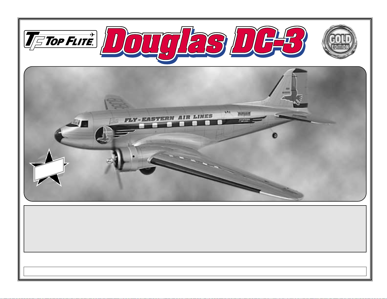
Wingspan: 82-1/2" [2095 mm]
Wing Area: 750 sq. in. [48.4 sq. dm]
Weight: 8 - 10 Lbs. [3629 - 4536g]
Wing Loading: 24.6 - 30.7 oz./sq. ft. [75 - 94 g/sq. dm]
Fuselage Length: 55.5 in. [1410 mm]
USA
Page 2
TABLE OF CONTENTS
AND BUILDING SEQUENCE
INTRODUCTION...........................................................2
PRECAUTIONS............................................................3
DECISIONS YOU MUST MAKE...................................3
Engine selection.........................................................3
Retractable landing gear............................................3
Flaps ..........................................................................3
Scale rudder...............................................................4
Propellers...................................................................4
COMPETITION-MINDED MODELERS ........................4
DOCUMENTATION ......................................................4
DESIGNER NOTES......................................................4
OTHER ITEMS REQUIRED..........................................5
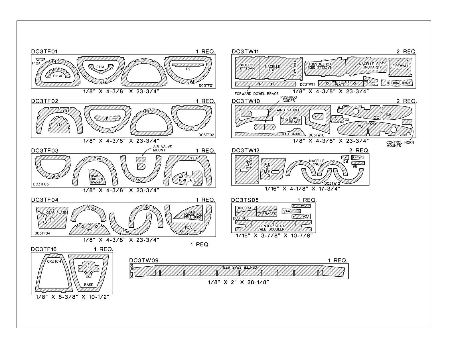
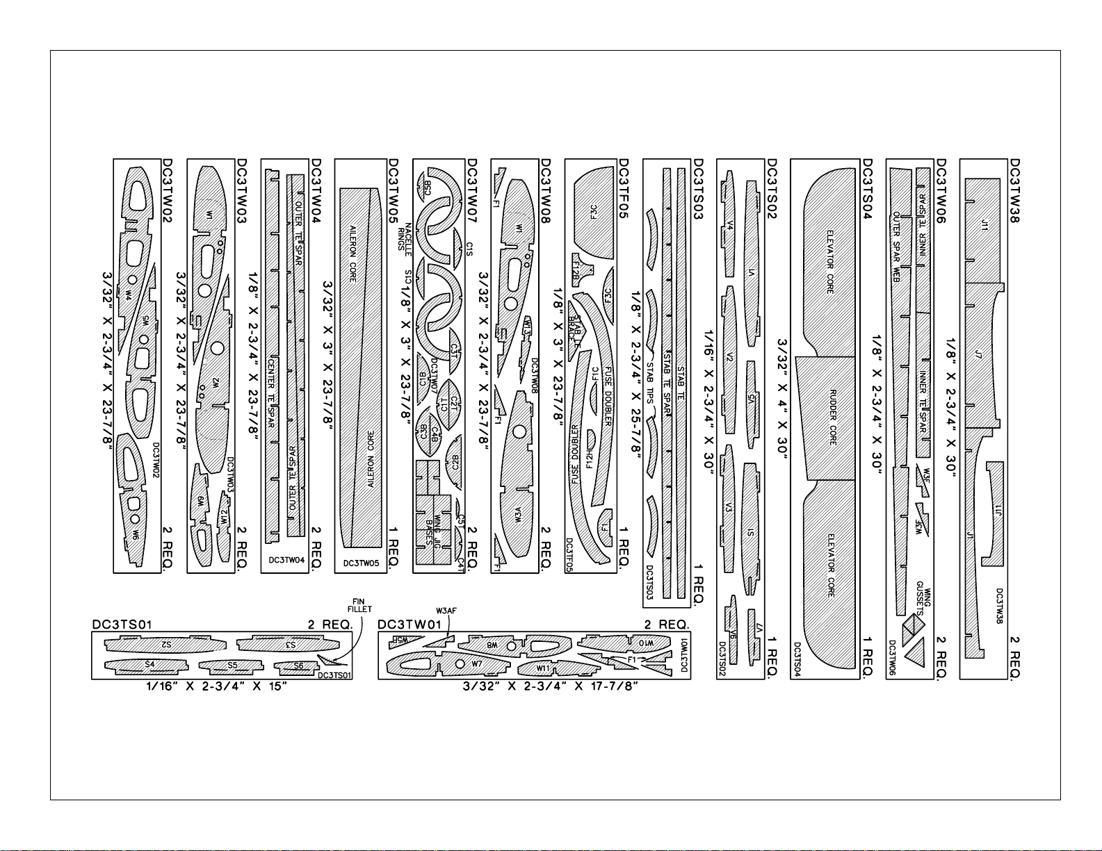
DIE-CUT PATTERNS.............................................6 & 7
BUILDING SUPPLIES..................................................8
Glue & Fillers..............................................................8
Tools ..........................................................................8
IMPORTANT BUILDING NOTES.................................8
GET READY TO BUILD ...............................................9
BUILD THE TAIL SURFACES .....................................9
Make the stab & fin skins...........................................9
Build the stabilizer....................................................11
Build the elevators....................................................12
Build the fin and rudder............................................14
BUILD THE FUSELAGE ............................................20
Frame the fuselage top............................................20
Mount the stab and fin..............................................22
Sheet the top of the fuselage...................................24
Build the bottom of the fuselage...............................26
Install the pushrods..................................................26
Finish the bottom of the fuselage.............................28
Mount the aft hatch ..................................................30
Fit the cabin top........................................................31
Build the dorsal fin and fit the tail cone ....................32
BUILD THE WING ......................................................33
Build the center section............................................33
Build the outer panels ..............................................36
Join the outer panels to the center section ..............37
Mount the engine nacelles.......................................37
Mount the retracts....................................................38
Build the fixed landing gear......................................40
Prepare the bottom of the wing for sheeting............42
Make the wing skins.................................................43
Sheet the bottom of the wing ...................................43
Build the flaps...........................................................44
Mount the servos in the wing ...................................45
Prepare the wing for the top sheeting......................47
Sheet the top of the wing .........................................48
Build the ailerons......................................................48
Hookup the flaps and ailerons..................................50
Sheet the nacelles....................................................51
Mount the cowls.......................................................53
FINAL CONSTRUCTION............................................55
Mount the wing to the fuselage................................55
Build the wing fillet ...................................................55
Mount the fuel tanks and receiver............................56
Prepare the model for covering................................57
Balance the airplane laterally...................................58
FINISHING..................................................................58
Cover your model with MonoKote
®
...........................58
Covering sequence..................................................59
Painting....................................................................59
Join the control surfaces..........................................59
FINISHING TOUCHES ...............................................60
Decals......................................................................60
Panel lines................................................................61
GET YOUR MODEL READY TO FLY........................61
Check engine thrust angles......................................61
Balance your model .................................................61
Final hookups and checks........................................62
Control surface throws.............................................62
Setup your throttles..................................................62
PREFLIGHT................................................................63
Identify your model...................................................63
Charge your batteries...............................................63
Balance your propellers ...........................................63
Synchronize your engines........................................63
Find a safe place to fly.............................................64
Ground check your model........................................64
Range check your radio...........................................64
Checklist...................................................................64
ENGINE SAFETY PRECAUTIONS............................64
AMA SAFETY CODE .................................................65
FLYING.......................................................................65
Engine out................................................................65
Pitch Trim Changes..................................................65
Takeoff.....................................................................65
Flight ........................................................................65
Landing ....................................................................66
TWO-VIEW DRAWING ................................Back Cover
Your DC-3 is not a toy, but a sophisticated working
model that functions very much like an actual airplane.
Because of its realistic performance, if you do not
assemble and operate your DC-3 correctly, you could
possibly injure yourself or spectators and damage property.
To make your R/C modeling experience totally
enjoyable, get assistance with assembly and your
first flights from an experienced, knowledgeable
modeler. You'll learn faster and avoid risking your model
before you're truly ready to solo. Your local hobby shop
has information about flying clubs in your area whose
membership includes qualified instructors.
You can also contact the Academy of Model Aeronautics
(AMA), which has more than 2,500 chartered clubs
across the country. We recommend you join the AMA
which will insure you at AMA club sites and events. AMA
Membership is required at chartered club fields where
qualified flight instructors are available.
Contact the AMA at the address or toll-free phone
number below.
Academy of Model Aeronautics
5151 East Memorial Drive
Muncie, IN 47302
(800) 435-9262
Fax (765) 741-0057
or via the Internet at: http://www.modelaircraft.org
INTRODUCTION
Congratulations and thank you for purchasing the Top
Flite
Gold Edition
DC-3. We are sure you are eager to
build and fly your DC-3 just as we were eager to build
and fly our prototypes. Although this is a model of a
famous civilian transport, the Douglas DC-3, you can
easily build your model as the C-47 military version. If
this is your choice, all you really need to do is cover your
Your Top Flite Gold Edition DC-3 is intended for
scale and general sport flying including mild
aerobatics such as loops, stall turns, rolls, etc. Its
structure is designed to withstand such stresses. If
you intend to use your DC-3 for more rigorous types
of flying such as aggressive aerobatics or flying from
rough fields, it is your responsibility to reinforce
areas of the model that will be subjected to the
resulting unusually high stresses.
PROTECT YOUR MODEL,
YOURSELF & OTHERS
FOLLOW THIS IMPORTANT
SAFETY PRECAUTION
- 2 -
Page 3

model in a military trim scheme, add cargo door outlines
and a few more antennas here and there! Study your
own documentation for more details.
The nice thing about the
Gold Edition
DC-3 is that
although it is a highly detailed scale model with all the
goodies such as a realistic looking scale outline, built up
tail surfaces, retracts and flaps, it isa model of a transport
plane so you’ll have a stable model that you’ll look forward
to flying often! And with twin engines you’re sure to get all
the attention when you show up at your flying field!
One last note before you continue, we highly recommend
you get some pictures or a book about DC-3's (or C-47's)
or send for your documentation package as soon as
possible. This way, you can study the drawings and
photos to get a feel for how your DC-3 should look when
you’re done. This will also help you figure out what scale
details to add and decide on a trim scheme (you can also
dream about how cool your DC-3 is going to look when it’s
done!). One of the books we recommend is the Squadron
Signal Publications
DC-3 in Action
book No. 39
(SSPZ1149). It features lots of historical and technical
information as well as detailed drawings, photos, and
trim schemes.
Well, this should be enough to get your juices flowing, so
get your other projects off your workbench, say goodbye
to your significant other for a while and...keep reading!
Please inspect all parts carefully before you start to
build! If any parts are missing, broken or defective,
or if you have any questions about building or flying
this model, please call us at (217) 398-8970 or e-mail
us at productsupport@top-flite.com and we’ll be
glad to help. If you are calling for replacement parts,
please look up the part numbers and the kit
identification number (stamped on the end of the
carton) and have them ready when you call.
PRECAUTIONS
1. You must build the plane according to the plan and
instructions. Do not alter or modify the model, as doing
so may result in an unsafe or unflyable model. In a few
cases the plan and instructions may differ slightly
from the photos. In those instances you should
assume the plan and written instructions are correct.
2. You must take time to build straight, true
and strong.
3. You must use a proper R/C radio that is in first class
condition, the correct sized engines and correct
components (fuel tanks, wheels, etc.) throughout your
building process.
4. You must properly install all R/C and other
components so that the model operates properly on the
ground and in the air.
5. You must test the operation of the model before every
flight to insure that all equipment is operating and you
must make certain that the model has remained
structurally sound.
6. If you are not already an experienced R/C pilot, you
must fly the model only with the help of a competent,
experienced R/C pilot.
Remember: Take your time and follow instructions to
end up with a well-built model that is straight and true.
ENGINE SELECTION
Recommended engine size:
Two .25 to .40 cu. in. [4.0 to 6.5cc] 2-stroke
Two .40 to .52 cu. in. [6.5 to 6.5cc] 4-stroke
Two O.S. .30 cu. in [5cc] rotary
Your Top Flite Gold Edition DC-3 will perform well with
any of the engines within the recommended range, but
will handle best in an engine out situation with engines
closer to the higher end of the recommended size range.
The trade-off with larger engines is that you’ll have to
throttle back somewhat for your DC-3 to fly in a scale like
manner. If you choose to use .25 2-strokes, we
recommend stronger 2-strokes such as the O.S. .25 FX.
If you choose to use .40 2-strokes, “sport” .40's such as
the O.S. LA.40 perform well, but a .40 such as the O.S.
FX series will handle an engine out situation better. It’s
the same for 4-stroke engines; the .40 4-strokes have
plenty of power and will fly your DC well, but the .52's will
handle an engine out situation better.
The included Great Planes Adjustable Engine Mounts
will hold a range of engines from .25 cu. in. 2-stroke
through .40 cu. in. 4-stroke. The rotary engines use their
own integral backplate engine mounts.
RETRACTABLE LANDING GEAR
You may build your DC-3 either with fixed or retractable
landing gear. All the hardware you need for realistic
appearing fixed gear is supplied with this kit. We do,
however, provide detailed instructions on how to install
retractable landing gear available from Top Flite. The
Top Flite retractable landing gear recommended and
shown in this manual is custom made for this DC-3.
They are pneumatic to simplify installation and hookup.
You may choose to use another type of retract but it is
up to you to make modifications required to fit them.
For Retractable Landing Gear you will need these items:
❏ Top Flite DC-3 Retracts (TOPQ8276)
❏ Robart #188VR Variable Rate Air Control Kit
(ROBQ2302)
❏ Robart #164G Hand Pump with Gauge (ROBQ2363)
❏ Micro servo to operate air control valve
❏ (2) Nylon ball link and 1/16" ball (GPMQ3842)
❏ (4) 4-40 x 1/2" socket head cap screws (GPMQ3012)
❏ (4) 3/16" wheel collars (GPMQ4308)
❏ (4) #4 x 1/2" screws
❏ (2) #4 x 1/4" screws
❏ (4) 4-40 blind nuts
FLAPS
Your DC-3 is designed to incorporate scale split flaps;
however, flaps are optional and not necessary for an
excellent flying experience. Without flaps, the takeoff roll
is longer and the landing speed is faster. If you do not
wish to build the flaps, just disregard parts of the manual
involving flap construction.
DECISIONS YOU MUST MAKE
NOTE: We, as the kit manufacturer, provide you with a
top quality kit and great instructions, but ultimately the
quality and flyability of your finished model depends on
how you build it; therefore, we cannot in any way
guarantee the performance of your completed model,
and no representations are expressed or implied as to
the performance or safety of your completed model.
- 3 -
Page 4

The flaps are not difficult to build, but they do require
good craftsmanship to fit and operate well. Flaps add
nicely to the model's flight characteristics and scale
appearance. Slight trim changes are needed when flaps
are extended. The trim corrections are discussed later in
the manual during radio setup and you will find more
information on the use of the flaps in the
Flying
section.
For Flaps, you will need these additional items:
Two Standard servos
Y-connector
Servo extensions (if not part of the Y-connector)
SCALE RUDDER
You may build your DC-3 with either a standard in-line
hinged rudder or a scale appearing offset pinned hinge
rudder. The in-line hinged rudder is easier to build and is
hinged to the fin the same as any other model with
supplied CA hinges. But, the offset pinned hinge features
the offset hinge line characteristic of the DC-3. The scale
appearing offset hinged rudder does require more
craftsmanship to build than the standard rudder, so study
the plans carefully and think about it before you begin
that part of the model. All hardware required to build
either version is included with this kit.
PROPELLERS
Although there is no urgency at this point to decide
which propellers to use on your DC-3, we would like to
mention that we have had great success during our flight
testing using three-blade propellers. The nice thing about
using three-blade propellers with your DC-3 is first of all,
they provide more clearance between the propeller tip
and the fuselage, and second, they are scale! On the
O.S. .25 two-strokes we ran 10 x 4 three-blade
propellers. On the O.S. .52 four-strokes we ran 10 x 6
three-blade propellers. As with any model, you may
experiment with different propellers to find out what type
works best for you. We used Great Planes Aluminum
Spinner Hubs (GPMQ4630, 1/4-28 thread) which appear
scale as well.
COMPETITION-MINDED MODELERS
We designed our DC-3 from scale three-view drawings
supplied by Scale Model Research (address follows) and
photos taken of various DC-3's. The scale of your Gold
Edition DC-3 is 1:14, or one-fourteenth scale.
If you plan to enter your DC-3 in scale competition (it’s lots
of fun, and the runways are usually paved!), this kit qualifies
for Fun Scale and the
Sportsman
and
Expert
classes in
Sport Scale. Fun Scale and Sport Scale have the same
flight requirements where you must perform ten maneuvers
of which five are mandatory. The other five are up to you—
easy stuff like cycling your landing gear, a slow, low
“inspection pass” with flaps extended, or maybe a touchand-go. If you have never competed in a scale contest, you
could start out in Fun Scale. In Fun Scale, the only
documentation you need for static judging is any proof that
a full size aircraft of this type, in the paint/markings scheme
on your model, did exist. A single photo, a kit box cover,
even a painting is sufficient proof! If you’re interested,
contact the AMA for a rule book which will tell you
everything you need to know. Look in the back of the AMA
magazine (
Model Aviation
) for a schedule of events.
The trim scheme we selected for our prototype on the kit
box cover is taken from Eastern Air Lines’ DC-3-201
NC18124. The last passenger flight of this subject took
place on October 12, 1952 after logging over 57,000 hours
in the air. It was then displayed at the Smithsonian but now
resides at the new National Air & Space Museum in
Washington D.C.
If you are not concerned with a scale trim scheme you can
make a variation of the one on the box, or design your own.
If you are going to compete in scale competition use the
photos in your documentation package as a guide for your
trim scheme.
DOCUMENTATION
Three view drawings and photo packs of full size
DC-3s are available from:
Scale Model Research
3114 Yukon Ave, Costa Mesa, CA 92626
(714) 979-8058
Fax: (714) 979-7279
Other sources of scale documentation include Squadron
Signal Publication’s book No. 1149 C-47 Skytrain in
Action, and various static display models such as
Monogram’s No. 5610 1:48 scale Eastern Air Lines DC-3.
DESIGNER NOTES
THIS SECTION
CONTAINS CRITICAL INFORMATION
CONCERNING YOUR DC-3 MODEL
The Top Flite DC-3 is a sport scale model of the Douglas
DC-3. The full size aircraft is gentle and forgiving, owing to
its excellent design and limited power. It is a classic aircraft
that has been flying for over sixty years. But, as an
overpowered model, it can be difficult to fly. Past models of
the DC-3, from other companies, have had a reputation for
unforgiving flight characteristics. Not so the Top Flight
DC-3. Built according to the instructions, you will be
rewarded with an aircraft every bit as good as the full size
DC-3. It is therefore essential that you build your model
according to the instructions in this manual.
SCALE ACCURACY
The Top Flite DC-3 is a faithful reproduction of the full
size aircraft, with a few exceptions. Flight testing of the
prototype models showed the need for some changes to
improve stability so that the average sport modeler could
handle this twin engine model.
1. The chord at the wing tips has been increased by 8%
to improve the stalling characteristics.
2. The scale airfoil blends into an S8037 at the tip to
improve the stalling characteristics.
3. The wing tips have washout of 2 degrees.
4. The engine nacelles have been lengthened by 1/2" to
allow room for retractable landing gear.
5. The engine nacelles have been moved 1/2" further
away from the fuselage to improve prop clearance.
6. The vertical fin/rudder area has been increased by
25% to improve single engine handling.
7. The horizontal stab/elevator area has been increased
by 23% to improve pitch control.
8. The engines incorporate 4 degrees of left/right thrust,
and 6 degrees of down thrust.
POWER
With two .40 2-stroke engines (or .52 4-stroke) the model
will fly very well, but not in a scale-like manner, as it will be
overpowered. It will take off in under ten feet and climb like
a typical overpowered model. Many modelers will like this,
but this is not my idea of a sport scale model of a DC-3. Of
course, one could control the throttles to fly the model in a
scale-like manner and save the reserve power for times
when it could be used effectively.
- 4 -
Page 5

TWIN ENGINE AERODYNAMICS
A twin engine model flies no differently than a single
engine model - as long as both engines are properly
tuned and as long as both engines stay running! But sooner or later, you will lose an engine. I ask you, how
often do you lose an engine on your single engine
models? You’ll lose one twice that often on a twin!
If you lose an engine on a twin, there will be a directional
control problem! If the right engine fails, the left engine will
pull the nose of the aircraft to the right. On a full size aircraft
you use rudder to control the yaw and carefully control the
airspeed with the remaining engine. Do not use the rudder
on this DC-3 if an engine quits. Flying at too slow an
airspeed with one engine at full power could exceed the
ability of the control surfaces to control the yaw.
But with a model, you are standing on the ground and
can’t really tell which engine quit. About the only thing
you will notice from the ground when an engine fails is
that the wing will drop slightly on that side and the nose
will yaw a bit, much like hitting a bit of turbulence. You
simply don’t have enough visual clues to know which
control inputs will help and which will hurt.
Fortunately, the Top Flite DC-3 flies so well with an engine
out that you do not need to make any immediate control
inputs to control the model. As long as you maintain
adequate flying speed you will hardly notice that an engine
failed. This is where your engine selection will have an
influence. If you have installed .40 size 2-stroke engines,
or .30 Wankels, the model has more than adequate power
to continue flying on one engine. It will slow somewhat,
but it will fly very nicely. You will have plenty of time to
enter the pattern and land. If you have installed .25 size 2stroke engines the model will slow quickly and you will
need to make an immediate landing. Just don’t allow the
model to get slow as there won’t be enough power to
accelerate without descending.
HOW TO HANDLE AN ENGINE FAILURE
If you have installed .25 size engines the model will slow
rapidly when an engine fails. The DC-3 is after all a high
drag aircraft. In this case you should reduce power on the
remaining engine and then glide back for a landing, just as
you would with a single engine model. DO NOT ATTEMPT
TO STRETCH YOUR GLIDE BACK TO THE RUNWAY
WITH HIGH POWER ON THE REMAINING ENGINE.
If you have installed larger engines you should have
adequate power to continue flying almost normally. I say
“almost” as there is a very important thing to consider; If
you allow the model to get too slow, you will lose control
when the yaw from the remaining engine overpowers the
effectiveness of the rudder. On twin engine aircraft the
fin/rudder will stall long before the wing does - full size or
model. The key is don’t get slow if the remaining engine
is at a high power setting. If you do, the model will do a
most beautiful snap roll. Recovery is easy - pull the good
engine to idle, lower the nose and glide in for a landing.
FLIGHT CHARACTERISTICS
Other than engine-out flying characteristics, there are a
few other flight qualities you should be aware of. The
engines are placed quite low in relation to the center of
the aircraft. This causes a pitch change when power is
changed. This is most noticeable when you go from idle
power to full power at a low airspeed - such as during a
go-around. Be prepared for this, adding a little down
elevator until the speed increases. Larger engines make
this characteristic more pronounced.
The placement of the fuel tanks in this model is difficult.
Although the best location for the tanks is in the nacelles,
if you are installing retracts the only available place is in
the wing center section. Modern engines have good fuel
draw so this should not create a problem, but older tired
engines may have difficulties. We did not experience any
problems with the many types of engines we tested on
our prototypes, but we did note one unusual thing: In a
turn the engines will have a slight RPM change. The low
engine will decrease RPM by a couple hundred and the
high engine will gain a couple of hundred. While slight,
this is enough for the aircraft to yaw slightly. It appears
that the aircraft is skidding in the turn, and it is! (A skid is
where the nose turns into the turn).
TWIN ENGINE TRAINING
Your Top Flite DC-3 represents a substantial investment
in time and money. For that reason, I suggest that you
start your multi-engine training with a model that you
won’t be so emotionally involved with. Get a Hobbico
TwinStar™for your training. It’s an ARF and will go
together in a couple of weekends. It is an excellent twin
engine trainer. It will save some serious knee knocking
time verses risking your Top Flite DC-3 and, it’s
inexpensive. Use the same engines on it that you will
use on your DC-3 so that you may thoroughly break
them in.
OTHER ITEMS REQUIRED
These are additional items you will need to complete
your DC-3 that are
not included
with your kit. Order
numbers are in parentheses (GPMQ4130). Our
exclusive brand is listed where possible: TOP is the Top
Flite brand, GPM is the Great Planes brand, and HCA is
the Hobbico brand.
❏ 4 to 8 Channel radio with 6 to 9 servos (2 micro
servos required for throttle)
❏ Y-connector for aileron servos
❏ (2) 12" Servo extensions for aileron servos
❏ Y-connector or (2) 12" extensions for throttle servos
(see page 46 for more info on throttle hookup)
❏ (2) 3-1/4" Main Wheels (GPMQ4226)
❏ (4) 3/16" Wheel Collars (only required if installing
fixed landing gear) (GPMQ4309)
❏ 1-1/2" Tail wheel (GPMQ4283)
❏ (2) 3/32" Wheel Collars for tail wheel (GPMQ4302)
❏ (2) 8 oz. (GPMQ4103) (for smaller engines) or 10 oz.
Fuel Tanks (GPMQ4104)
❏ Approximately 80" medium silicone fuel tubing
(3) 36" pkgs. (GPMQ4131)
❏ (2) Fuel filler valves (GPMQ4160)
❏ (2) Propeller hubs (GPMQ4630)
❏ 1/2" (HCAQ1050) or 1/4" (HCAQ1000) R/C Foam
rubber padding
❏ 3 rolls of Top Flite Super MonoKote covering, see
Finishing
on page 58
❏ Paint, see
Finishing
on page 58
❏ Propellers
For additional information on how to handle your DC-3
in an engine out situation, refer to the “Engine Out”
section on page 65.
- 5 -
Page 6
- 6 -
DIE-CUT PATTERNS
Page 7
- 7 -
DIE-CUT PATTERNS
Page 8
BUILDING SUPPLIES
Here’s a checklist of supplies you should have on hand
while you’re building. Some of these are optional. Use
your own experience to decide what you need. We
recommend Great Planes Pro™CA and Epoxy.
GLUE/FILLER
❏ 4 oz. Thin CA (GPMR6004)
❏ 4 oz. Medium CA+ (GPMR6010)
❏ 2 oz. Thick CA- (GPMR6015)
❏ CA Accelerator (GPMR6035)
❏ CA Debonder (GMPR6039)
❏ CA Applicator Tips (HCAR3780)
❏ 30-minute (GPMR6047)
or
❏ 45-minute (GPMR6048) epoxy
❏ 6-minute epoxy (GPMR6045)
❏ Pro Wood Glue (GPMR6161)
❏ Microballoons (TOPR1090)
❏ Milled Fiberglass (GPMR6165)
❏ Lightweight Hobby Filler (Balsa Color, HCAR3401)
❏ Auto body filler (Bondo®or similar)
❏ Isopropyl Alcohol (to clean up excess epoxy)
TOOLS
❏ #11 Blades (HCAR0311, 100 qty.)
❏ Single Edge Razor Blades (HCAR0312, 100 qty.)
❏ Razor Plane (MASR1510)
❏ Hobbico Builder’s Triangle (HCAR0480)
❏T-Pins (HCAR5100 (S), HCAR5150 (M), HCAR5200 (L)
❏ Drill Bits: 1/16", #41 (or 3/32"), 9/64" (or 1/8"), 5/32",
1/4", #10 (or 3/16") (or 1/4-20 tap and drill set),
#43(or 4-40 tap and drill set)
❏ 1/4-20 Tap and drill (GPMR8105)
❏ 4-40 Tap and drill (GPMR8101)
❏ Tap wrench (GPMR8120)
❏ Curved Tip Scissors (HCAR0667)
❏ Long handle 9/64" ball end hex wrench (GPMR8004)
❏ Silver Solder w/flux (GPMR8070)
❏ Great Planes Plan Protector (GPMR6167) or wax paper
❏ Masking Tape
❏ Easy–Touch
™
Bar Sanders*
❏ Dremel®#178 cutting bit for countersinking screws
in the servo hatch covers
RECOMMENDED COVERING TOOLS
AND ACCESSORIES
❏ Top Flite Heat Gun (TOPR2000)
❏ Top Flite Trim Seal Tool (TOPR2200)
-and-
❏ Top Flite Sealing Iron (TOPR2100)
❏ Top Flite Hot Sock (TOPR2175)
-or-
❏ 21stCentury Sealing Iron (COVR2700)
❏ 21stCentury Cover Sock (COVR2702)
EASY-TOUCH™BAR SANDER
*A flat, durable, easy to handle sanding tool is a
necessity for building a well finished model. Great
Planes makes a complete range of Easy-Touch Bar
Sanders (patented) and replaceable Easy-Touch
Adhesive-backed Sandpaper. While building the DC-3
we used two 5-1/2" Bar Sanders and two 11" Bar
Sanders equipped with 80-grit and 150-grit Adhesivebacked Sandpaper. Here's the complete list of EasyTouch Bar Sanders and Adhesive Backed Sandpaper.
5-1/2" Bar Sander (GPMR6169)
11" Bar Sander (GPMR6170)
22" Bar Sander (GPMR6172)
33" Bar Sander (GPMR6174)
44" Bar Sander (GPMR6176)
11" Contour Multi-Sander (GPMR6190)
12' roll of Adhesive-backed sandpaper:
80-grit (GPMR6180)
150-grit (GPMR6183)
180-grit (GPMR6184)
220-grit (GPMR6185)
Assortment pack of 5-1/2" strips (GPMR6189)
We also use Top Flite 320-grit (TOPR8030, 4 sheets)
and 400-grit (TOPR8032, 4 sheets) wet-or-dry
sandpaper for finish sanding.
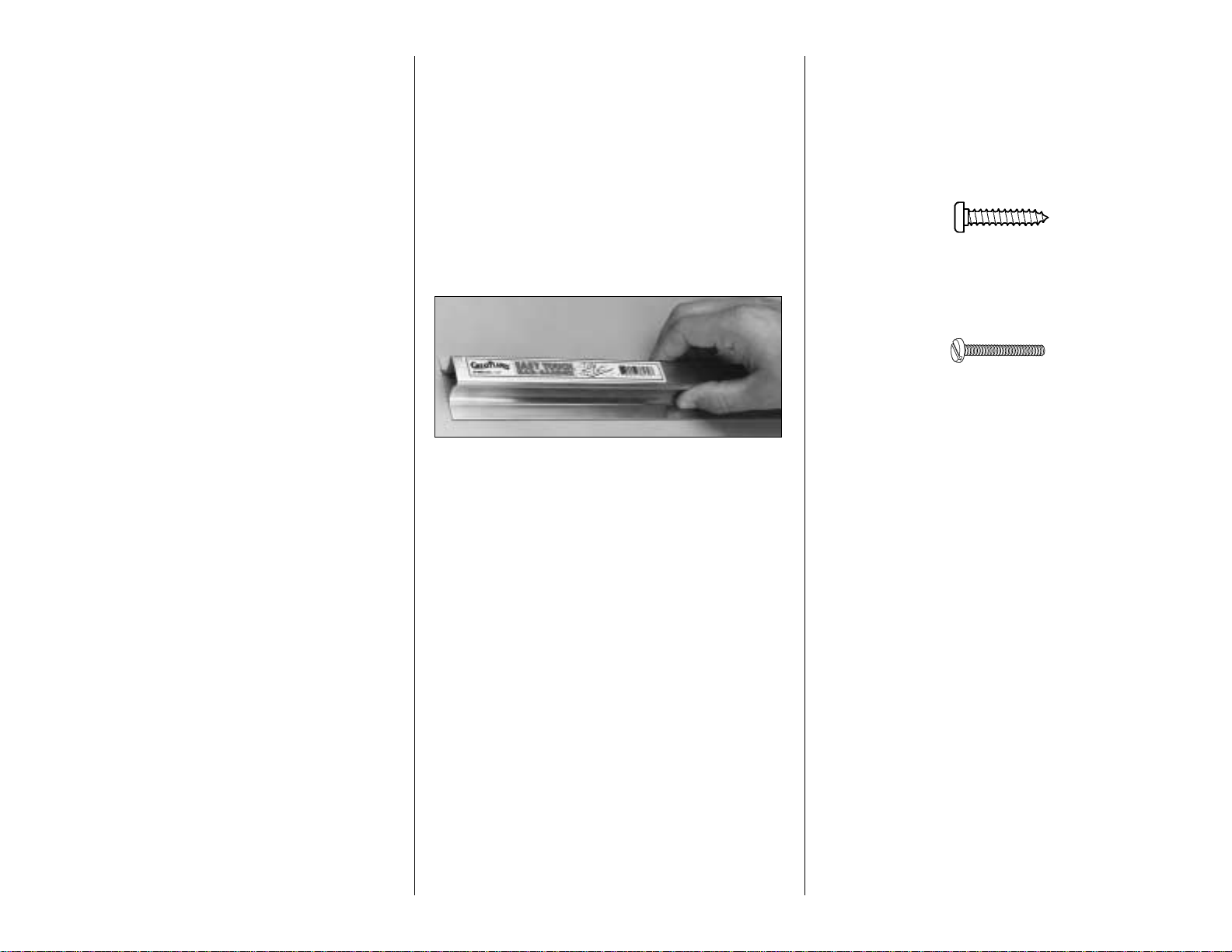
IMPORTANT BUILDING NOTES
•
There are two types of screws used in this kit.
Sheet metal screws are designated by a number
and a length.
For example #6 x 3/4" [19.1mm]
Machine screws are designated by a number,
threads per inch and a length.
For example 4-40 x 3/4" [19.1mm]
•
When you see the term
test fit
in the instructions, it
means that you should first position the part on the
assembly without using any glue, then slightly modify
or
custom fit
the part as necessary for the best fit.
•
Whenever the term
glue
is used you should rely upon
your experience to decide what type of glue to use.
When a specific type of adhesive works best for that
step we will tell you what type of glue to use.
•
Whenever just
epoxy
is specified you may use
either
30-minute epoxy or6-minute epoxy. When 30-minute
epoxy is specified it is highly recommended that you
use only 30-minute (or 45-minute) epoxy because you
will need the working time and/or the additional strength.
•
Occasionally we refer to the
top
or
bottom
of the model
or upor
down
. To avoid confusion, the
top
or
bottom
of the model is as it would be when the airplane is
right side up and will be referred to as the top even if
the model is upside down during that step,
i.e.
the top
main spar is always the top main spar even if the wing
is upside down when you are working on it. Similarly,
move the former up
means move the former toward
the top of the fuselage even if the fuselage is upside
down when you are working on it.
•
When you get to each step, read that step completely
through to the end before you begin. Frequently there
is important information or a note at the end of the step
that you need to know before you start.
- 8 -
Page 9
•
Photos and sketches are placed ahead of the step
they refer to. Frequently you can study photos in
following steps to get another view of the same parts.
COMMON ABBREVIATIONS
Deg = degrees Elev = elevator
Fuse = fuselage " = inches
LE = leading edge Ply = plywood
Stab = stabilizer TE = trailing edge
LG = landing gear mm = millimeters
TYPES OF WOOD
BALSA BASSWOOD PLYWOOD
GET READY TO BUILD
1. Unroll the plan sheets. Roll them inside out so they lie
flat. Cut the left fuselage plan where indicated along the
dashed line and tape it to the right fuse plan
where indicated.
2. Remove all the parts from the box. Use a ballpoint pen
(not a felt tip pen) to lightly write the name or size on each
piece so you can identify it later. Use the
die-cut patterns
on pages 6 & 7 to identify and mark the die-cut parts
before you remove them from their die sheets. Many of
the parts already have numbers stamped on them, but in
some cases the number is located alongside the parts or
only on the die drawings on pages 6 and 7. You may
remove all the die-cut parts from their die sheets now or
wait until you need them. If a part is difficult to remove,
don’t force it out but cut around it with a #11 blade. After
you remove the parts from their die sheets, lightly sand
the edges to remove slivers or die-cutting irregularities.
Save some of the larger scraps of wood.
3. Separate the parts into groups such as stab, fin,
wing, and fuse. Store smaller parts in zipper-top food
storage bags.
BUILD THE TAIL SURFACES
MAKE THE STAB & FIN SKINS
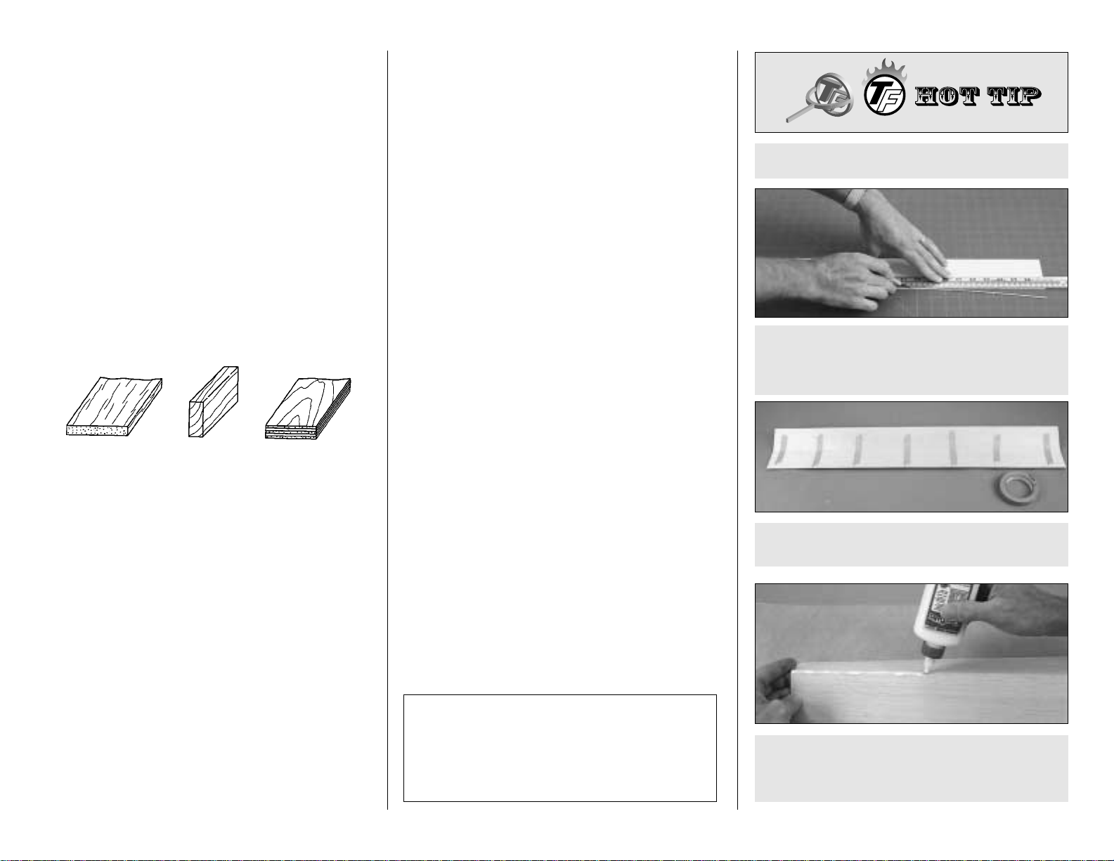
❏ 1. Use the
Hot Tip
that follows or your own method
to glue two 1/16" x 3" x 30" balsa sheets together to
make a 1/16" x 6" x 30" sheet for one of the stab skins.
❏ C. Place a sheet of Plan Protector or wax paper on
your workbench. Turn the taped together sheets over
and apply aliphatic resin (wood workers glue such as
Great Planes Pro) to the seams.
❏ B. Tightly tape the trued edges of the sheets together
with masking tape.
❏ A. Use a straightedge and a sharp #11 blade to
true one edge of both sheets. Do not cut all the way
through the first time but make several passes with
your knife to prevent the wood from splitting.
HOW TO MAKE THE STAB SKINS
Top Flite selects balsa that is intended for sheeting,
though occasionally a few of these sheets may have
a small nick or split near the ends. If your kit contains
a few of these sheets, arrange them and glue them
together so the defects will not interfere with the final
shape of the skin.
1/64" = .4mm
1/32" = .8mm
1/16" = 1.6mm
3/32" = 2.4mm
1/8" = 3.2mm
5/32" = 4mm
3/16" = 4.8mm
1/4" = 6.4mm
3/8" = 9.5mm
1/2" = 12.7mm
5/8" = 15.9mm
3/4" = 19mm
1" = 25.4mm
2" = 50.8mm
3" = 76.2mm
6" = 152.4mm
12" = 304.8mm
15" = 381mm
18" = 457.2mm
21" = 533.4mm
24" = 609.6mm
30" = 762mm
36" = 914.4mm
METRIC CONVERSION
1" = 25.4mm (conversion factor)
- 9 -
Page 10
❏ 2. Now that you’re familiar with making skins (if you
weren’t so already), make two more skins to be used for
the other side of the stab and both sides of the fin (after this
step you should have three 1/16" x 6" x 30" balsa sheets).
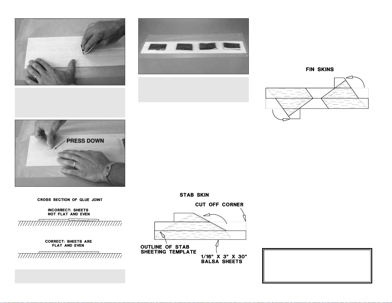
❏ 3. Cut the stab sheeting pattern and the scale or non-
scale fin sheeting pattern from the plan (make sure you
use the correct fin sheeting pattern depending on which fin
you are going to build). If you’re not sure yet which fin to
build, you can wait until later to cut the fin skin.
❏ 4. Place the stab sheeting pattern over one of the
skins. Cut one of the corners off the balsa sheet as
shown in the sketch and glue it to the front of the sheet
so it will be large enough to make a stab skin. After the
glue dries cut the skin slightly larger than the pattern to
allow some room for positioning. Make another stab skin
the same way.
❏ 5. Make two fin skins from the last 6" x 30" sheet
using the fin sheeting pattern as shown in the sketch.
Make sure you accurately cut the bottom of the fin skins
where they fit the stab because this helps to set the fin
at the correct angle to the stab and fuse.
❏ 6. After your skins are glued together and cut out,
remove the masking tape and sand the skins flat with
your bar sander and fresh 150-grit sandpaper. The idea
is to sand the skins before you glue them into place.
This minimizes low spots that can occur over the ribs
from sanding too much after you glue the sheeting
down. Set your fin and stab skins aside for now.
This is the same procedure we will recommend when it
is time to make the wing skins.
DC-3
Fact
The DC-3 has many names including
Dizzy Three,
Dakota, Skytrain, Spooky, Puff the Magic Dragon
and probably the most common,
Gooney Bird
.
❏ F. Place weights on top of the sheets to hold them
down (
see
page 12 on how to make
weight bags
). We
prefer plastic bags filled with lead shot, but anything
similar will do the job.
❏ E. Inspect the seam and press the sheets together
where they do not align.
❏ D. Use a credit card or something similar to
simultaneously press the sheets flat as you squeegee
the excess glue from the seam. Wipe the glue off your
squeegee so it’s ready for the next time. Immediately
proceed to the next step.
- 10 -
Page 11
BUILD THE STABILIZER
❏ 1. Cut the stab plan along the dashed line and tape it
to your building board. Cover the stab plan with
Plan Protector.
❏ 2. Glue the die-cut 1/8" balsa stab TE spar to the
die-cut 1/8" balsa stab TE. These pieces are
symmetrical so it does not matter how you join them.
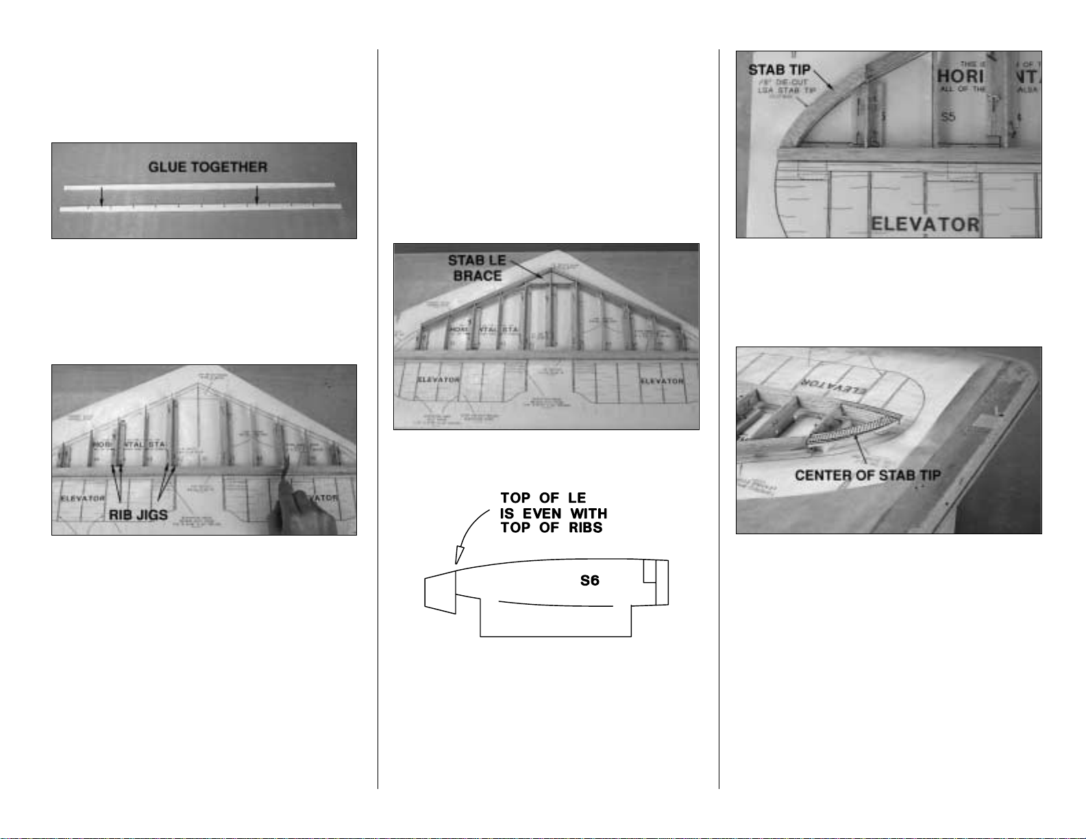
❏ 3. Insert all the die-cut 1/16" balsa stab ribs except
for rib S1 in the TE spar and place the assembly over
the plan.
❏ 4. Cut rib jigs from two 1/4" x 5/16" x 24" balsa sticks
and pin them to the plan on both sides of ribs S6, S4
and S2. Save the leftover 1/4" x 5/16" sticks for use
later. Make sure none of the rib jigs or the T-pins extend
beyond the front of the ribs. The rib jigs hold the ribs in
alignment over the plan without having to stick T-pins
through the ribs (which can be difficult). Use a small
square to align the trailing edge over the plan.
❏ 5. Make sure all the ribs are fully seated into the TE
and that the jig tabs are contacting the building board.
Use a square to make sure the TE is perpendicular to
your building board. Glue the ribs to the TE with thin CA.
❏ 6. Cut a 1-1/2" long piece from a 1/4" x 3/4" x 30"
balsa stick and glue it to the TE where shown on the
plan for the rudder torque rod block.
❏ 7. Glue rib S1 to the rudder torque rod block using two
more rib jigs to hold it in place like you did with the
other ribs.
❏ 8. Sand a bevel on the front of the ribs to
accommodate the aft sweep of the LE. Insert the die-cut
1/8" balsa stab LE brace in rib S1 between ribs S2
where shown on the plan. You can see the stab LE
brace in the next photo.
❏ 9. Cut the ends of both 5/16" x 15" shaped balsa
stab/fin leading edges so they match the plan. Position
one of the LE’s on the front of the ribs so the top of the
LE is even with the top of the ribs and glue into place.
Glue the other LE to the stab and glue the stab LE brace
into place.
❏ 10. Glue two die-cut 1/8" balsa stab tips together to
make a stab tip. Make another stab tip the same way.
Glue the stab tips to the stab where shown on the plan.
Make sure the tips are centered (vertically) on tip ribs S6
and the trailing edge.
❏ 11. Relocate any T-pins that are protruding above the
structure so they will not be in the way when you sand
the stab tip and the leading and trailing edges. Use a bar
sander and 80-grit sandpaper to bevel the top of the
stab tips to accommodate the sheeting. Shape the top of
the TE and LE to blend with the stab tips and the ribs.
We’ve marked the centerline of the stab tip and
highlighted the top of it so you can see how the stab tip
is tapered.
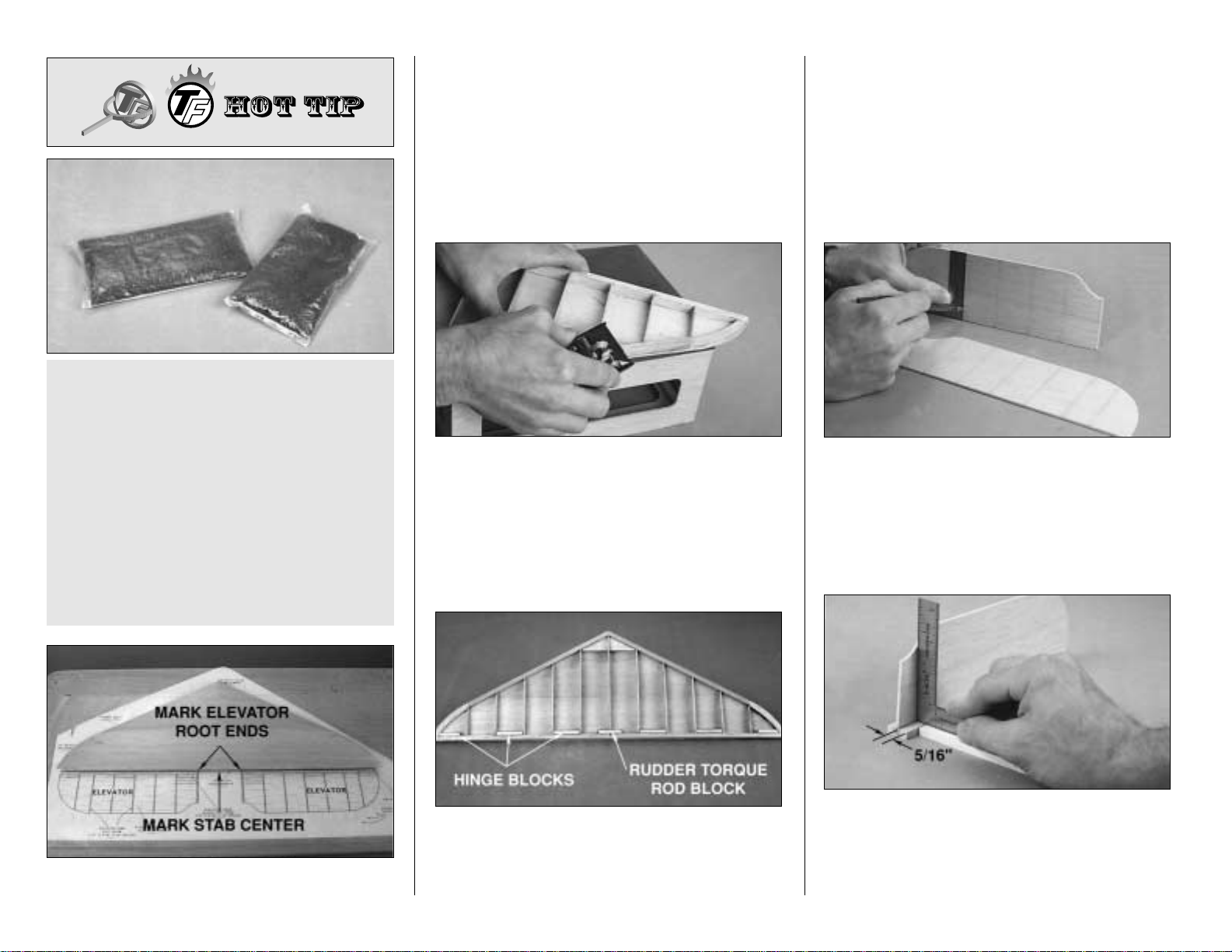
❏ 12. Before you sheet the top of the stab, refer to the
photo at step13. Use a ballpoint pen and a square to
mark the center of the stab and the root end of both
elevators on the TE of the stab. The marks will help you
align the stab with the fuse and align the elevators with
the stab later on.
- 11 -
Page 12
❏ 13. Sheet the top of the stab with one of the stab skins
you’ve already prepared. We recommend using aliphatic
resin to glue the skin to the ribs and CA to glue the skin to
the TE, LE and tips. Wet the outside of the sheeting in the
middle near the leading edge. Apply aliphatic resin to the
ribs and position the top skin on the stab. Place your
weights on top of the stab skin, then use CA to glue the
skin to the LE, TE and tips. Leave the weights in position
until the aliphatic resin dries—thirty minutes to an hour is
enough time.
❏ 14. Remove the stab from your building board. Save
the rib jigs for building your fin. Turn the stab over and
cut the jig tabs from the bottom of the ribs, then trim the
bottom of the LE even with the ribs. Trim the stab tips
and the bottom of the TE near the tips the same way
you did on the top. Trim the bottom of the rudder torque
rod block even with the ribs.
❏ 15. Cut the stab hinge blocks from the same 1/4" x
3/4" balsa stick you used for the rudder torque rod block
a few steps earlier. Glue the hinge blocks to the TE, ribs,
and top sheeting where shown on the plan. Trim the
hinge blocks even with the TE and ribs.
❏ 16. Sheet the bottom of the stab with the other stab
skin you prepared. Use care not to add any twist to the
stab as it is no longer supported by the jig tabs. Once
again, we suggest using aliphatic resin to glue the skin
to the ribs and medium CA for the rest.
BUILD THE ELEVATORS
❏❏1. Mark the location of the elevator ribs on both sides
of one of the die-cut 3/32" balsa elevator cores where
shown on the plan. The easiest way to do this is to mark
just the front of the elevator, then use a small square to
extend the lines with a ballpoint pen. Note the alternate
scale location of the elevator ribs shown on the plan.
❏❏2. Cut the remainder of the 1/4" x 3/4" balsa stick
you used for the stab hinge blocks and an additional
1/4" x 3/4" x 30" balsa stick to the length shown on the
plan for the elevator leading edge. Use a straightedge
to draw line 5/16" from the edge of the elevator leading
edge. Glue the elevator core to the LE along the line—
When we glue sheeting to a structure (wing, stab, fin),
we use plastic bags filled with lead shot to hold the
sheeting down. These plastic bags filled with lead
take the shape of the curved surfaces to apply
uniform pressure and do not put marks in the balsa
wood. You can purchase lead shot at most stores
where hunting supplies are sold. We use #6 lead
shot. One 25 lb. bag costs approximately fifteen to
twenty dollars. You may use small zip lock food
storage bags to hold the shot. Tape the bags shut to
make sure they don’t open. Each bag should hold
between two to three lbs. of lead. Ten to fifteen twoto-three lb. bags should be enough for most projects.
You can see how we position our “weight bags”
further ahead in the manual during wing construction.
- 12 -
Page 13
not directly on top of the line. Use a square to make sure
you glue the LE perpendicular to the elevator core.
Hint: Place a 1/4" piece of balsa under the square to
raise it to the level of the LE.
❏ 3. Prepare the other elevator the same way.
❏ 4. Apply about four small drops of medium CA, evenly
spaced, along the LE of one of the elevators and tack
glue it to the stab. When in place, the root end of the
elevator LE should be 1/16" beyond the mark you made
on the TE of the stab to accommodate the elevator root
cap ribs (refer to the plan). The elevator LE should also
be centered vertically on the stab TE. Practice alignment
before you tack glue the elevator. Tack glue the other
elevator to the other side of the stab the same way.
❏ 5. Use a razor plane or your bar sander to shape the
leading edge of the elevators to match the stab.
❏ 6. Use four 1/16" x 5/16" x 24" balsa sticks to make the
elevator ribs, and a piece of leftover 1/16" sheeting to
make the elevator root cap ribs (refer to the plan) for the
root end of the elevators. If you’ve decided to make the
scale location elevator ribs, use leftover 1/16" balsa
sheeting to make the additional ribs. Cut the sticks to the
correct length, then glue them to the elevator cores only
(don’t glue the elevator ribs to the elevator LE yet) making
sure the cores remain perpendicular to the LE’s as you
proceed. You can see the ribs in the following photo.
❏ 7. Make the elevator hinge blocks from a 1/4" x
5/16" x 24" balsa stick and 1/4" x 5/16" balsa you have
leftover from the rib jigs when you were building the
stab. Glue the hinge blocks to the elevators as shown on
the plan. Now you may glue the elevator ribs to the LE.
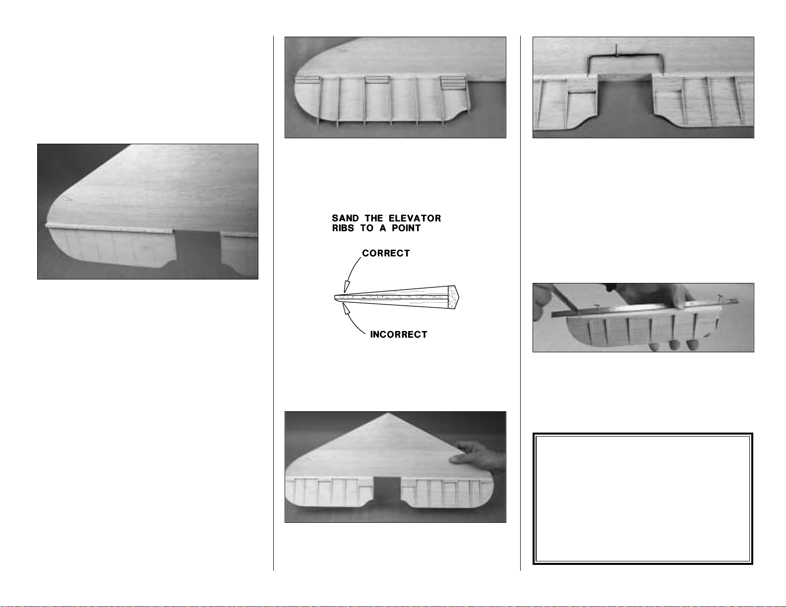
❏ 8. Proceed slowly and carefully, shaping the elevator
ribs and the hinge blocks to match the elevator LE and
the cross section on the plan. Make sure you sand the
ends of the ribs to a point as shown in the sketch.
Otherwise, covering the elevators will be difficult.
There. Now you have a nicely constructed stab with
elevators that accurately match. Just a few more things
to do and then we’ll move on to the fin and rudder
(which version are you going to build?)
.
❏ 9. Determine which side of the stab looks the best.
Designate that side as the top. Use a file or a rotary tool
with a cut-off wheel to remove sharp edges or burrs on
the ends of the elevator joiner wire. Position the elevator
joiner wire on the top of the stab as shown in the photo.
Mark the leading edge of the elevators where the
arm
portion of the joiner wire will enter as shown on the plan
❏ 10. Carefully
break
both elevators free from the stab.
Note which elevator matches which side of the stab.
Remove any
glue bumps
left from the CA you used to
tack glue the elevators to the stab.
❏ 11. Insert T-pins through the center of one of the
elevators LE’s, near the tip and near the root. Place a
straightedge across the T-pins and draw the centerline
on the elevator LE with a ballpoint pen. Draw a
centerline along other elevator LE and the TE of the stab
the same way.
DC-3
Fact
After presiding over various projects including the
Martin MB-2 bomber at the Glenn L. Martin
aircraft company, Donald W. Douglas Jr, born
April 6, 1892, co-founded the Davis-Douglas
Aircraft Company in the spring of 1920 with help
from David Davis, a millionaire with a great desire
to fly. By the mid 20's, Douglas designs were well
known throughout both the civilian and military
aircraft industry.
- 13 -
Page 14
❏ 12. Mark the location of the hinge slots on the
elevators and stab where shown on the plan. With a #11
blade, cut the hinge slots in the elevators and the stab
along the centerlines you marked earlier
❏ 13. Using the sketch above, cut six hinges from the
CA hinge strip supplied with this kit. Snip the corners
off so they go into the slots easier. You may cut all the
hinges now, or cut them as you need them.
❏ 14. Test fit the hinges into the slots. If the hinges do
not slide into the slots easily, work your knife blade back
and forth in the slot a few times to provide more
clearance (it is really the back edge of the blade that
does the work here in widening the slot).
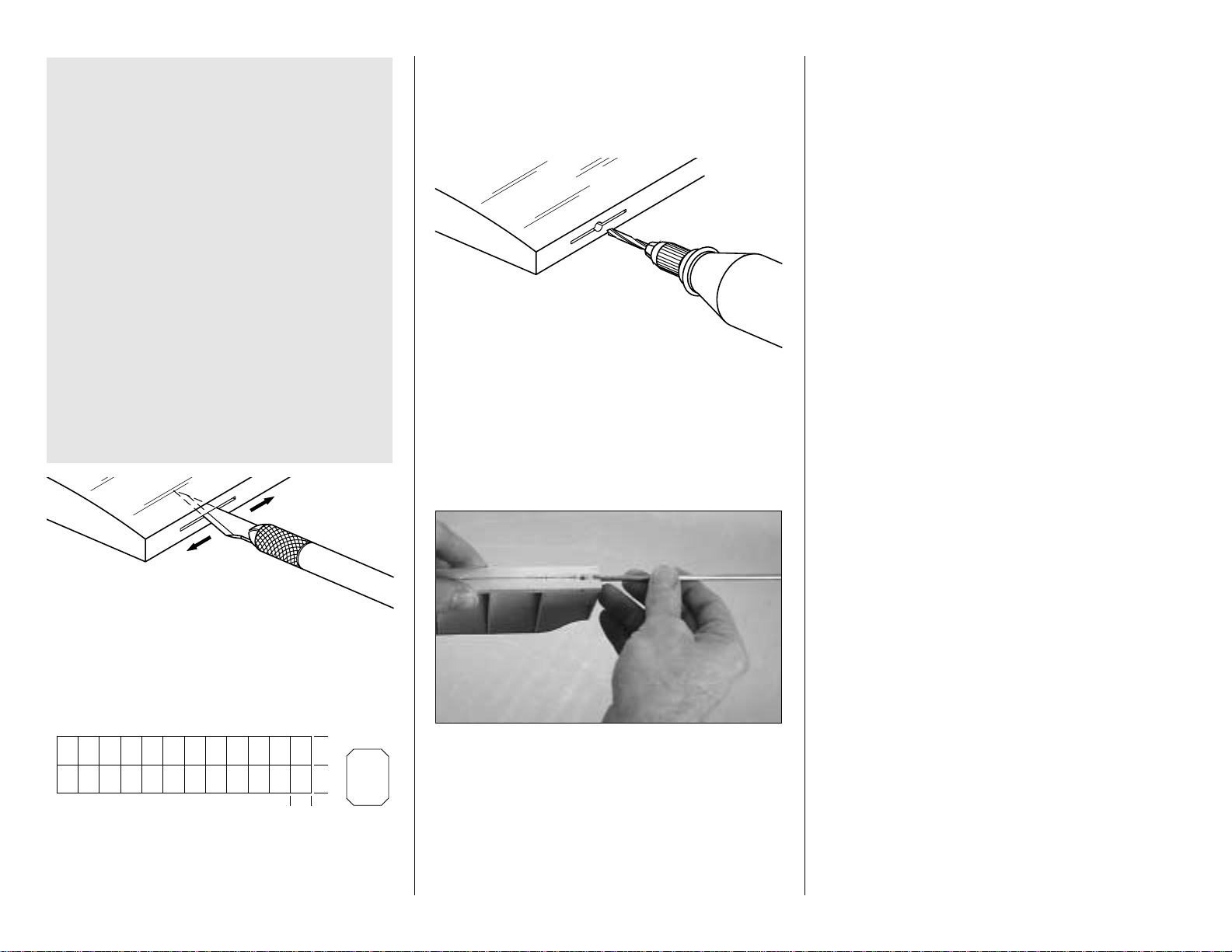
❏ 15. Drill a 3/32" hole, 1/2" deep in the center of the
hinge slots. Use a rotary tool with a 3/32" drill bit or a
carbide cutter for the best results. Reinsert your knife
blade to
clean out
the slot after you drill the holes.
❏ 16. Test fit the elevators to the stab with the hinges. If
any hinge slots are not wide enough or are misaligned,
make adjustments so the elevators accurately fit the stab.
❏ 17. Drill a 9/64" (or 1/8") hole at the marks you made
on the centerline of both elevator leading edges for the
joiner wire. Cut a groove in the leading edge of both
elevators to accommodate the joiner wire.
Hint: Use a 5/32" brass tube sharpened at one end to
cut the grooves.
❏ 18. Bevel the leading edges of the elevators to a “V” as
shown on the cross section of the plan. Use the centerline
on the elevator leading edges as a guide. Test fit the
elevators to the stab with the joiner wire and the hinges.
Note that the horn on the joiner wire points downward.
Cut a small notch in the TE of the stab for the horn on the
joiner wire. If necessary, remove the joiner and
tweak
it so
both elevators are in the same plane.
❏ 19. Once more, test fit the elevators to the stab with
the hinges and the joiner wire. Make sure you can obtain
the control throws indicated on page 62 of the manual. If
you cannot, increase the “V” on the leading edge of
the elevators.
Set the stab and elevators aside.
BUILD THE FIN AND RUDDER
Now it’s time to decide which fin and rudder to build.
The non-scale fin and rudder is easier to build than the
scale fin and rudder while retaining the distinctive DC-3
outline. However, the scale fin and rudder utilize the
offset rudder hinge and balance tab. If you go for the
scale fin and rudder, we guarantee you’ll sit back and
grin as you watch others study the offset fin and rudder
on your DC-3 and admire your craftsmanship.
If you are going to build the non-scale fin and
rudder, proceed with the instructions that follow. If
you are going to build the scale fin and rudder, skip
to “Build the scale fin and rudder” on page 16.
Build the non-scale fin and rudder
❏ 1. Cut the fin and rudder plan from the fuse plan along
the dashed line and tape it to your building board. Cover
the plan with Plan Protector.
❏ 2. Apply medium CA to the embossed cutlines near the
trailing edge of the die-cut 1/16" fin ribs V1 through V7.
IMPORTANT NOTES ABOUT CA HINGES
This kit is supplied with a CA hinge material
consisting of a 3-layer lamination of Mylar and
polyester. It is specially made for hinging model
airplane control surfaces. When properly installed,
this type of CA hinge provides the best combination
of strength, durability and easy installation. We trust
all of our Gold Edition war birds to these hinges, but
it is essential to install them correctly. Carefully
follow the hinging instructions in this manual for the
best result.
The most common mistake made by modelers
when installing CA hinges is making the hinge slots
too tight restricting the flow of CA to the back of the
hinges; or not using enough glue to fully secure the
hinge over its entire surface area. This results in
hinges that are only
tack glued
into the hinge slots.
The techniques for cutting the hinge slots and
gluing in CA hinges (near the end of the manual)
have been developed to ensure thorough and
secure gluing.
- 14 -
WITH HOBBY KNIFE
CUT HINGE SLOT
AND #11 BLADE
1"
1"
3/4"
DRILL A 3/32" HOLE
1/2" DEEP, IN CENTER
OF HINGE SLOT
Page 15
❏ 3. The same way you did for the stab, use your 1/4" x
5/16" rib jigs to hold the balsa fin ribs V1 through V7
over their location on the plan. Use a square to align the
ends of the ribs with the TE on the plan.
❏ 4. Cut the fin TE from a 1/8" x 1/2" x 24" balsa stick.
Align the top of the fin TE with the tops of the ribs allowing
the excess to protrude below the ribs (to be trimmed later)
and glue the fin TE to the fin ribs with thin CA.
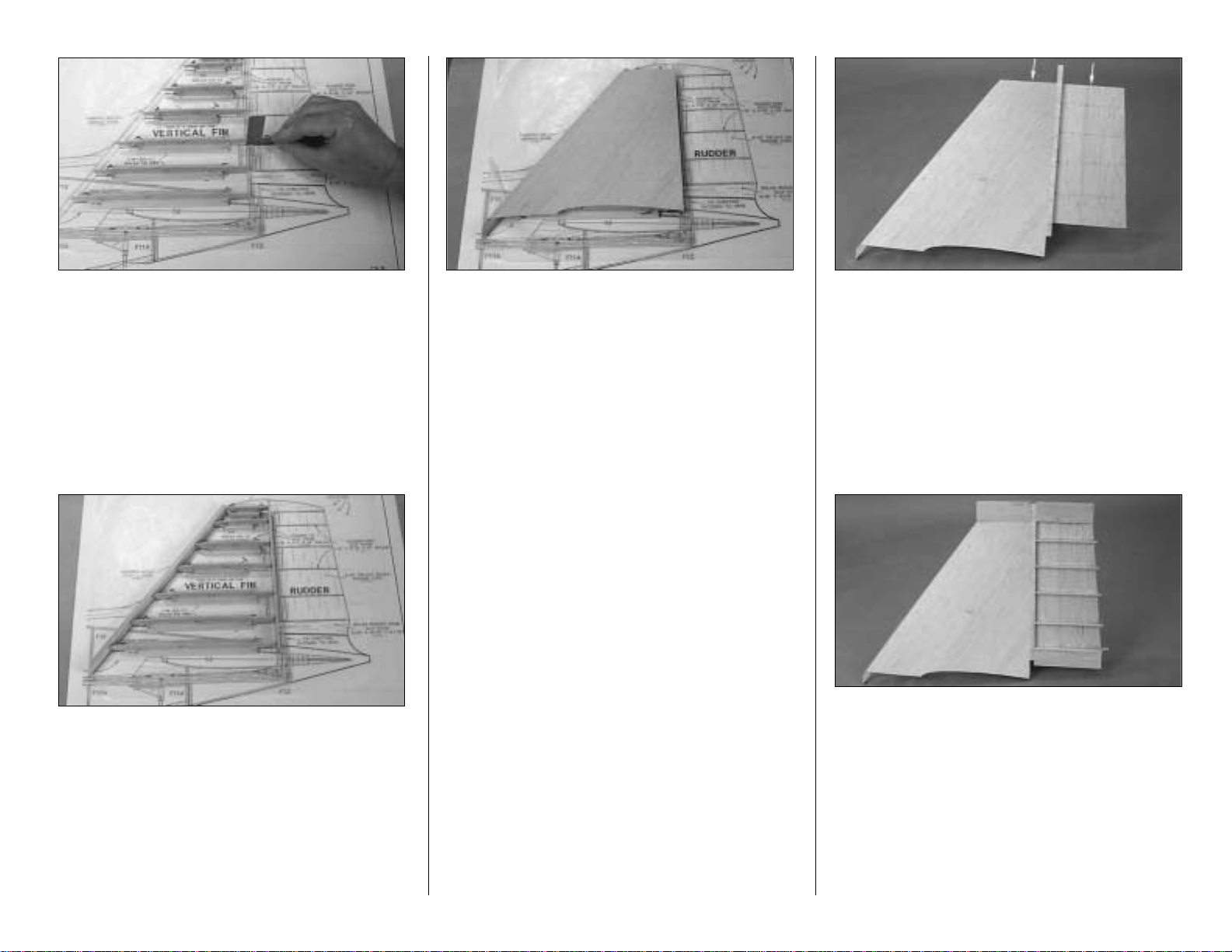
❏ 5. Bevel the front of the fin ribs to accommodate the
fin LE. Cut the fin LE as shown on the plan from a 5/16"
x 15" shaped balsa stab/fin leading edge stick. Glue the
fin LE to the fin the same way you did the stab with the
excess protruding below the ribs.
❏ 6. Rearrange any T-pins that protrude above the
structure so they will not interfere with your bar sander.
Lightly sand the top of the LE and TE to match the airfoil
shape of the ribs to accommodate the fin skin.
❏ 7. If you haven’t yet done so, cut out your fin skins.
Sheet the left side of the fin with one of your fin skins
(don’t forget to use your left skin so the best looking side
is out). Make sure you position the skin accurately
because the bottom of the skin is what determines the fit
of the fin to the stab.
❏ 8. Remove the fin from your building board and trim
off the jig tabs. Trim the LE and TE to match the ribs.
❏ 9. Cut the fin hinge blocks from your leftover rib jigs
and glue them to the TE of the fin where shown on
the plan.
❏ 10. Sheet the other side of the fin with your other fin
skin. Be careful not to build any twist into the fin as you
press the skin in place.
❏ 11. Use your bar sander to sand the TE and top of the
fin square and even.
❏ 12. Trim 1/16" from the top of the die-cut 3/32" balsa
rudder core. Mark the location of the rudder ribs on
both sides of the rudder core.
❏ 13. Cut the remainder of the 1/4" x 3/4" x 30" balsa
stick you used for the elevator LE’s to the length shown
on the plan for the rudder LE. The same way you did for
the elevator LE’s, use a straightedge to draw a line 5/16"
from one edge of the rudder LE. Glue the die-cut 3/32"
balsa rudder core to the LE along the line. Use a square
to make sure you glue the core perpendicular to the LE.
❏ 14. Tack glue the rudder LE, centered, to the fin TE
with about four small drops of medium CA. Note that the
top of the rudder core is aligned with the top of the fin.
❏ 15. Use a razor plane or your bar sander to shape the
leading edge of the rudder to match the fin.
❏ 16. Refer to the following photo. From the 5/8" x
1-1/4" x 13" balsa block cut a 3-3/4" long piece for the
fin tip, 2-3/4" long piece for the rudder tip and a 3-1/2"
long piece for the rudder base. Glue the tips and base
in position (do not glue the fin tip to the rudder LE).
❏ 17. Use two 1/16" x 5/16" x 24" balsa sticks to make
the rudder ribs and glue them to the rudder core.
❏ 18. See the following photos and carefully taper the
rudder ribs and the rudder tip and rudder base toward the
rudder TE. Make sure you sand the ends of the ribs to a
point the same way you did for the elevator ribs. Carefully
shape the fin tip and the rudder tip to match the plan and
each other. Finish by rounding the leading edge of the fin,
then the fin and rudder tips. Don’t worry about shaping
the bottom of the rudder at this point. We can do that
when we join the tail cone to the fuse and rudder.
- 15 -
Page 16
❏ 19. Cut the rudder hinge blocks from leftover rib jigs
and glue them to the rudder core and rudder LE where
shown on the plan. Blend the rudder hinge blocks to
the rudder.
❏ 20. The same way you did for the elevators and stab,
carefully
break
the rudder free from the fin, draw a centerline
on the rudder LE and the fin TE, mark and cut the hinge
slots, then drill the holes in the hinge slots and test fit the
rudder to the fin with the hinges. Bevel the leading edge of
the rudder to a “V.” Make sure you can achieve the throw
recommended on page 62 of the manual.
❏ 21. Mark the location of the rudder torque rod on the
rudder. Drill a 9/64" (or 1/8") hole at the mark you made
and cut a slot to accommodate the vertical part of the rod.
❏ 22. Tape the fin and rudder plan back to the fuse plan,
accurately aligning the reference lines.
Set the fin and rudder aside. Skip to “Build the
Fuselage” on page 20
(there’s another DC-3
Fact
within
the scale fin and rudder section that you may be
interested in).
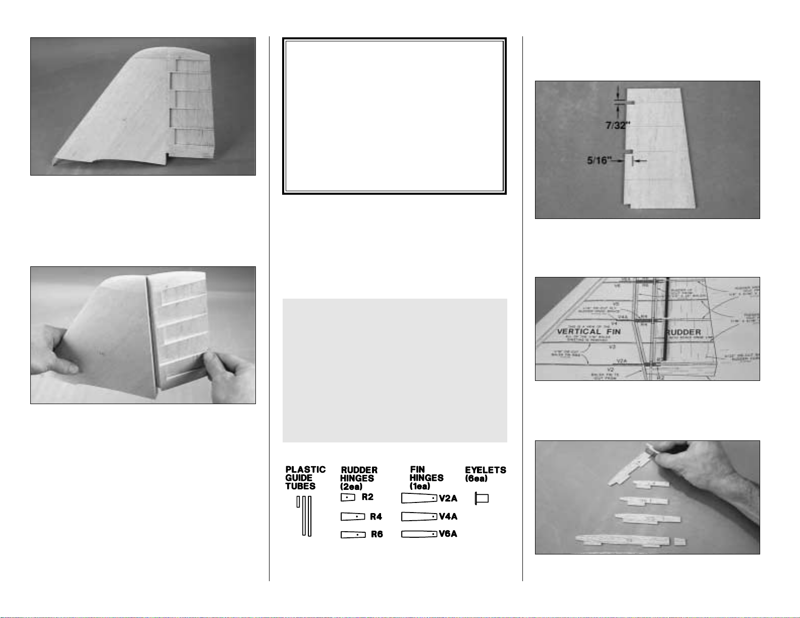
BUILD THE SCALE FIN AND RUDDER
For easier identification while you proceed, here is a
drawing of some of the fin and rudder parts.
❏ 1. Cut the scale fin and rudder plan along the dashed
line and tape it to your building board. Cover the plan
with Plan Protector.
❏ 2. Accurately cut three 7/32" slots, 5/16" deep, in the diecut 3/32" balsa rudder core in the location shown on the
plan to accommodate the rudder hinges. Mark the location
of the rudder ribs on both sides of the rudder core.
❏ 3. Accurately cut three guide tubes to the length
shown on the plan from a 3/16" x 36" outer pushrod
tube. Use coarse sandpaper to roughen the outside of
the guide tubes so the glue will stick.
❏ 4. Cut the die-cut 1/16" balsa fin ribs V2 through V7
at the embossed cutline toward the aft end of the ribs.
Before you proceed, it will be easier for you to build
the fin and rudder if you are able to visualize how
the hinge system operates and how all the parts fit
together. To do this, study the photos in this section
before you continue. Further, if you’ve ever had
aspirations of being a “neat and tidy” builder, now is
the time to exercise those thoughts—refrain from
using lots of glue and do not build up large fillets
that will interfere with sanding or the fit of joining
parts. Take your time and you’ll end up with a
beautiful scale fin and rudder that all of your friends
will marvel at.
DC-3
Fact
By the late 20's the air transportation industry was
rapidly expanding with small airline companies
springing up everywhere. Though major players
such as United, Transcontinental, Western and
American Airlines were well established, the
aircraft they used featured metal skinned, wooden
framed construction—technology leftover from
WWI aircraft. This
set the stage
for the demand
for an aircraft that could serve the growing
industry. Whichever aircraft that would be was
surely destined to become famous.
- 16 -
Page 17
❏ 5. The same way you did for the stab, use your 1/4" x
5/16" rib jigs to hold the fin ribs V1 through V7 over their
location on the plan. Use a square to align the ends of
the ribs with the TE on the plan.
❏ 6. From the 1/8" x 3/4" x 30” balsa stick cut the four
fin TE sections that fit between ribs V7 and V6, ribs V6
and V4, ribs V4 and V2, and ribs V2 and V1. Don’t forget
to cut the bottom two sections long enough so you can
bevel the ends to the correct angle shown on the plan.
All the TE sections must be cut accurately and the ends
must be square (vertical).
❏ 7. Glue the fin TE sections to the fin ribs as shown on
the plan. Make sure the jig tabs of the ribs and each TE
section are resting on your building board over their
locations on the plan. Make sure you provide the 1/16"
space for the three plywood fin hinges where required.
❏ 8. Drill a 1/8" hole at the punch mark through all three
sets of die-cut 1/16" plywood rudder hinges R2, R4 and
R6. Press down on each piece as you drill to prevent the
wood from splitting as the drill goes through.
❏ 9. Drill a #41 (or 3/32") hole at the punch mark
through the three die-cut 1/16" plywood fin hinges V2A,
V4A and V6A.
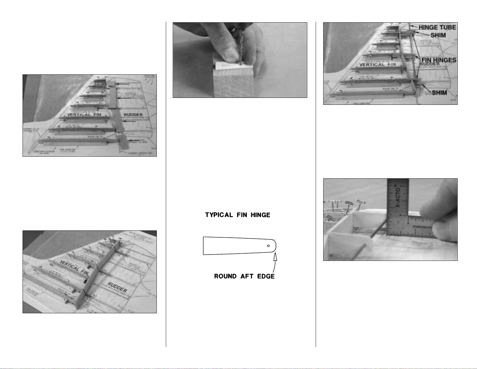
❏ 10. Round the aft edge of the fin hinges as indicated
in the sketch and as shown in the photo at step 13.
❏ 11. Slide the 3/32" x 10" brass hinge tube into the
holes of the ply fin hinges. Space the hinges along the
hinge tube as shown on the plan and insert the hinges
into the fin assembly (refer to the following photo).
❏ 12. Make sure the hinges and the hinge tube will align
with the plan. If necessary, trim parts of the TE sections
or glue bumps that interfere. Make two small shims
from the 3/32" x 7/16" x 24" balsa stick and place them
under the hinge tube near the top and bottom hinges.
These will hold the tube level and align the fin hinges
with the fin.
❏ 13. Make sure the fin hinges are accurately aligned
with the fin ribs and that the hinge tube is aligned with its
location over the plan. Confirm by measuring the height
of the tube at each hinge. Glue the fin hinges to the ribs
with thin CA.
❏ 14. Bevel the front of the fin ribs to accommodate the
fin LE. Cut the fin LE as shown on the plan from a 5/16"
x 15" shaped balsa stab/fin leading edge stick. Glue the
fin LE to the fin the same way you did the stab with the
excess protruding below the ribs.
- 17 -
Page 18
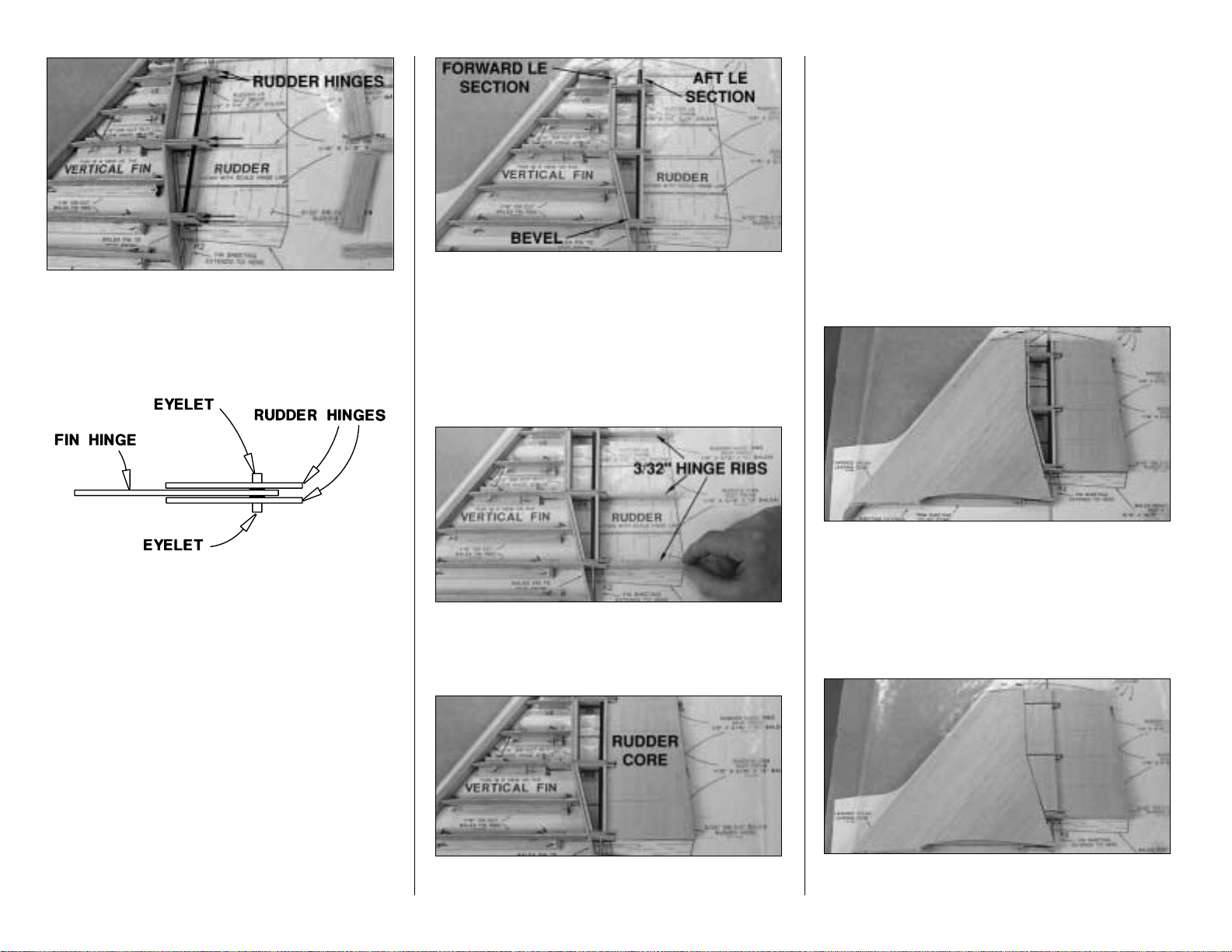
❏ 15. Insert an eyelet into each of the six rudder hinges.
Glue the eyelets in place with medium CA and allow to
fully cure before you proceed. Remove the brass hinge
tube from the fin and fit it through the fin and rudder
hinges as shown on the plan with the guide tubes you
cut earlier.
❏ 16. Cut the six forward and aft rudder LE sections
from the remainder of the 1/8" x 3/4" x 30" balsa stick
you used for the fin TE sections. You can see them in
the next photo. The same as the fin TE sections, you
must cut each rudder LE section accurately. Bevel the
bottom front forward LE section as shown on the plan.
❏ 17. Test fit but do not glue the rudder LE sections
where shown on the plan. Make adjustments as
necessary for a good fit. Add the top guide tube.
Are you
beginning to see how it works?
❏ 18. Cut the six 3/32" rudder hinge ribs (three for
each side of the rudder) from the 3/32" x 7/16" x 24"
balsa stick and the six 1/16" rudder ribs from the 1/16"
x 7/16" x 24" balsa stick.
❏ 19. Place the three 3/32" rudder hinge ribs between
the rudder hinges over the plan. These ribs will set the
correct
height
of the rudder core to keep it aligned with
the hinge line.
❏ 20. Fit the rudder core, resting on top of the 3/32" ribs,
to the hinges.
❏ 21. Place approximately 1/32" shims from cardstock
or something similar between the forward rudder LE
sections and the fin TE section. Carefully view the
structure, making sure everything is in alignment, and
glue the forward rudder LE sections to the ply rudder
hinges and glue the aft rudder LE sections to the rudder
core, hinge guides, and rudder hinges. Also glue the
rudder core to the rudder hinges. Make sure you do not
glue any of the rudder parts to any of the fin parts!
❏ 22. Rearrange any T-pins that protrude above the
structure so they will not interfere with your bar sander.
Lightly sand the top of the fin LE and TE and the rudder
LE sections to match the airfoil shape of the ribs, to
accommodate the fin skin.
❏ 23. If you haven’t already done so, cut out the fin skins.
Sheet the left side of the fin with one of the skins (don’t
forget to use your left skin so the good side is out). Make
sure you position the skin accurately because the bottom
of the skin is what determines the fit of the fin to the stab.
You may use medium CA for this if you work quickly and
carefully. Make sure you don’t inadvertently glue the
forward rudder LE to the fin TE or fin skin!
❏ 24. Use leftover 1/16" balsa to sheet the LE of the
rudder over the rudder LE sections as shown in the
- 18 -
Page 19
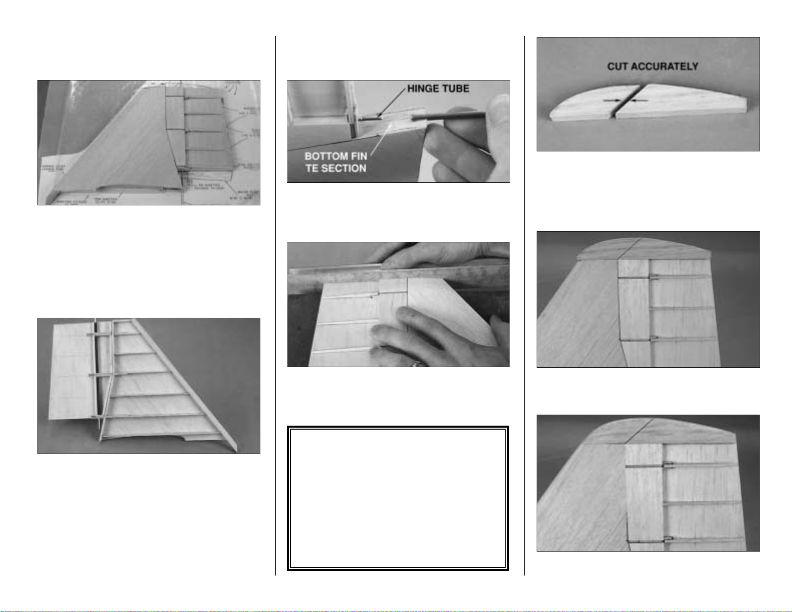
photo. Be careful not to get any glue between the fin
hinge and the rudder hinges and don’t glue the rudder
sheeting to the fin sheeting.
❏ 25. Glue the rudder ribs you cut earlier to the left side
of the rudder core. Shape the ribs to match the cross
section on the plan and lightly sand the rudder sheeting
to match the fin.
Looking pretty good aye? All you have to do now is
finish the other side and add the tip blocks!
❏ 26. Carefully remove the fin and rudder from your
building board. Turn the assembly over and cut the jig
tabs from the ribs and trim the LE and TE sections to
match the airfoil and the cross section on the plan (the
same way you did with the other side of the fin and
rudder before you sheeted it).
❏ 27. Sheet the right side of the fin with the other fin
skin you prepared earlier. Use leftover 1/16" sheeting to
sheet the right side of the rudder leading edge sections
as well.
❏ 28. Add the 1/16" and 3/32" balsa rudder ribs to the
rudder. Sand the ribs to match the cross section on the
plan and to match the left side of the rudder.
❏ 29. Use a 1/8" drill or a 1/8" brass tube sharpened at
one end to cut a small groove in the bottom fin TE
section so the hinge tube can pass (and the rudder
torque rod later on).
❏ 30. Push the brass hinge tube down into the rudder
until the top of the hinge tube is even with the top of the
fin. Use your bar sander and 80-grit sandpaper to sand
the top of the fin and rudder flat and even.
❏ 31. Make the fin tip and rudder tip from the 5/8" x
1-1/4" x 13" balsa block. At this time, the only parts of
the tips you have to cut accurately are the opposing
ends at the hinge line. The outline of the tips only has to
be rough. You can final shape and round them later.
❏ 32. Glue the fin tip to the fin and the rudder tip to the
rudder with an approximate 1/16" gap between them.
❏ 33. Use your razor plane and your bar sander to shape
the fin LE and the rudder and fin tip to match the plan.
DC-3
Fact
In the early 20's the airline industry giants
announced that
the call was out
for an airplane
that could satisfy the demands of the growing
airline industry. Boeing was first to answer that
call with an all metal, twin engine monoplane
named the Model 247. United Air Lines ordered
sixty 247's locking up the entire Boeing assembly
line. The result was that other airlines would have
to wait until the United contract was fulfilled
before they could “get in on the action.”
- 19 -
Page 20
❏ 34. Without separating the rudder from the fin (until
instructed to do so), carefully remove the brass hinge
tube by pulling it out from the bottom. Use a #11 blade
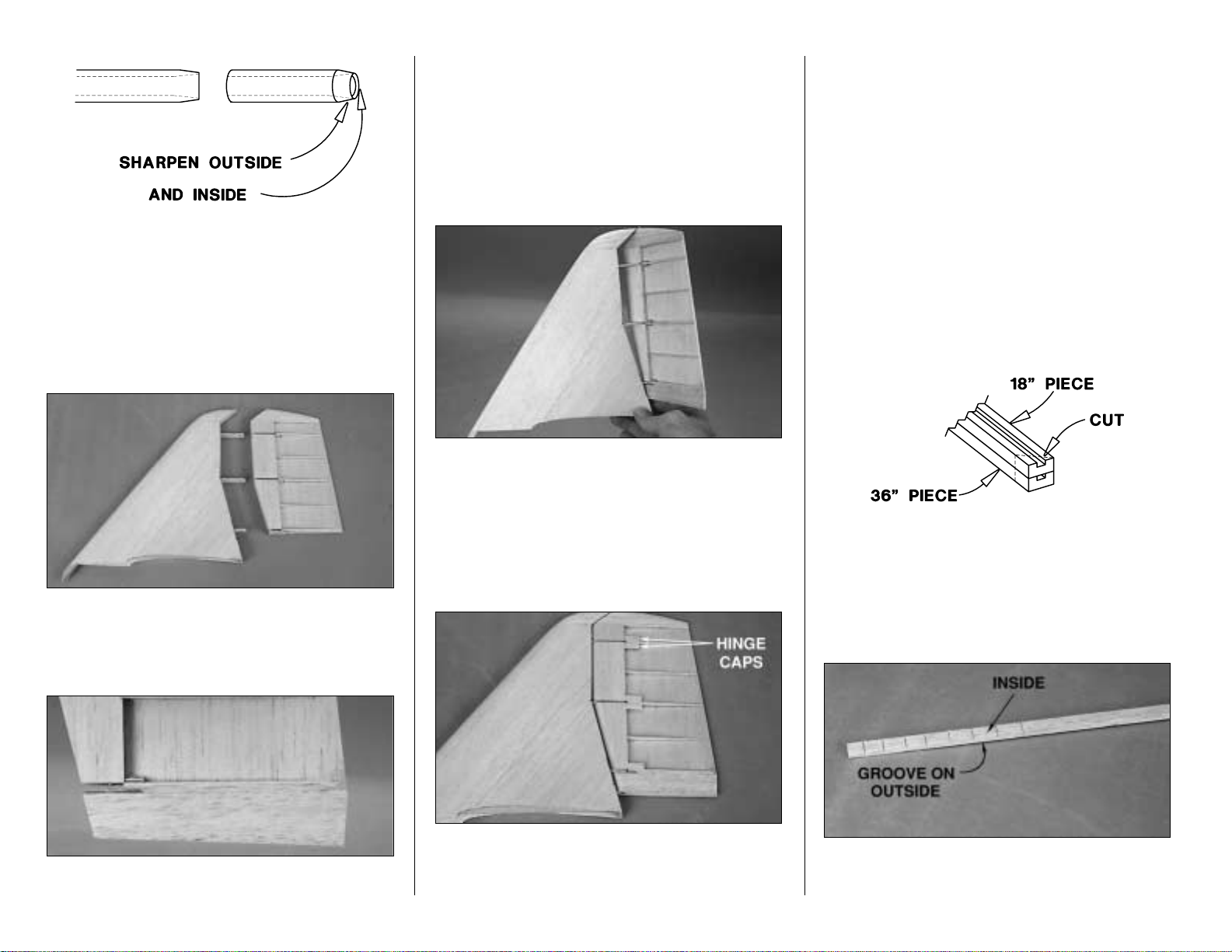
and a cut-off wßheel or file to sharpen one end of the
brass hinge tube as shown in the sketch and reinsert it
with the sharpened end going upward into the rudder.
Attach the bottom of the tube to a drill or a rotary power
tool and drill a
clean
hole up through the rudder tip block
until the brass hinge tube exits the top.
❏ 35. Now for the moment of truth. Pull the hinge tube
out and
carefully
separate the rudder from the fin.
There may be a few spots where you have inadvertently
glued the two together so be careful. Separate these
spots with a #11 knife if possible.
❏ 36. Glue the leftover piece of 5/8" x 1-1/4" balsa to the
bottom of the rudder and sand it to the shape of the
rudder base block shown on the plan. Fill the space
between the base block and the bottom rudder ribs with
leftover 1/16" balsa.
❏ 37. Use your sharpened brass hinge tube to drill a hole
through the rudder base block the same way you did the
rudder tip—only this time go down through the top.
❏ 38. Round the LE of the rudder as shown on the plan
to allow for control movement. Test fit the rudder to the fin
with the brass hinge tube. Move the rudder side to side
and look for areas that interfere with smooth movement.
Trim where necessary to achieve the control throws in the
back of the manual. Make sure the rudder tip and the fin
tip do not interfere. If they do, sand the front of the rudder
tip until you have achieved enough clearance.
❏ 39. Cut hinge caps from leftover 1/16" balsa and glue
them to the 3/32" ribs. These provide your covering with
something to bond to. Sand the hinge caps flush with
the rest of the rudder.
BUILD THE FUSELAGE
FRAME THE FUSELAGE TOP
❏ 1. If you haven’t already done so, tape the left fuse
plan to the right fuse plan so the dashed alignment
marks match up. Cut the fuselage top view from the rest
of the plan and tape it to your building board. Cover the
plan with Plan Protector.
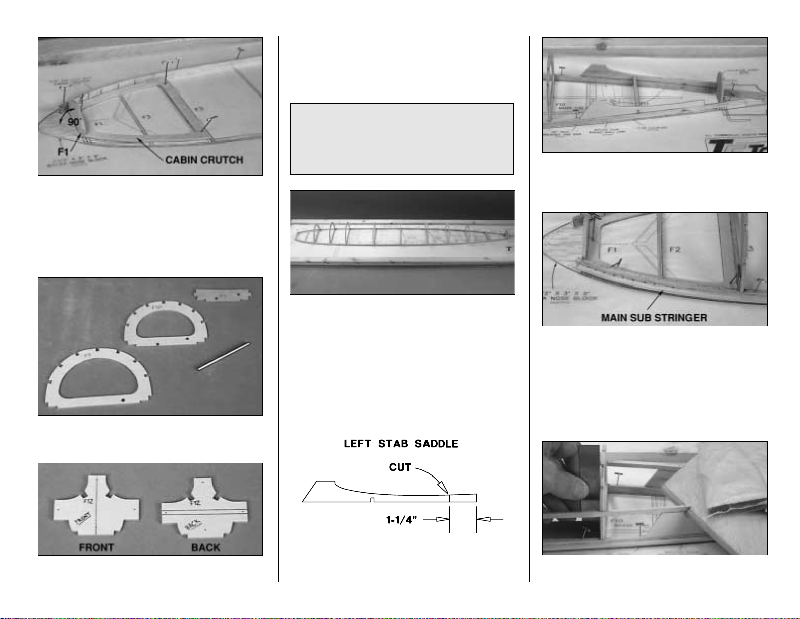
❏ 2. Refer to the photo at step six and glue the die-cut
1/8" balsa former F1 to the front of the die-cut 1/8"
plywood cabin crutch, making sure F1 is at a 90 degree
angle. After the glue dries, bevel the sides of F1 to
match the sides of the cabin crutch.
❏ 3. Pin the cabin crutch over its location on the plan.
❏❏4. Gather the three 3/16" x 3/8" x 36" grooved
main stringers. Cut one of the stringers into two 18"
long pieces. Place an 18" main stringer on top of a 36"
main stringer so the ends align. Cut the stringers near
the ends at approximately a 45 degree angle as shown
in the sketch (use your miter box if you have one). The
two angled cuts will be spliced together at former F-9.
❏❏5. Use a razor saw to cut small notches, 3/32"
deep, in the inside of the 36" stringer near the front so it
will bend around the cabin crutch.
- 20 -
Page 21
❏❏6. Pin the two stringers to the plan so the angled
splice
is at former F9 as shown on the plan. Glue the
front of the stringer to the cabin crutch and glue the
stringers to each other where they meet at F9.
❏ 7. Repeat steps 4, 5 and 6 with an additional 36" long
grooved main stringer and the remaining 18" long
grooved main stringer.
❏ 8. Refer to the
Pushrod Locations
area on the fuse
plan and drill 3/16" holes through the punch marks in the
die-cut 1/8" plywood formers F9, F10 and F11.
❏ 9. Drill 1/16" holes through the punch marks in the
die-cut 1/8" plywood former F12. Draw a vertical
centerline connecting both punch marks on one side of
F12 (this will be the front) and horizontal guidelines
1/16" above and below the punch marks on the other
side of F12 (this will be the back).
For illustration
purposes the photo shows two F12's.
❏ 10. Test fit all the die-cut 1/8" plywood formers (F2
through F10 and former F12) to the main stringers over
their location on the plan. You may need to bevel the
notches in some of the rear formers to accommodate
the angle at which they join the main stringers. Use a
small square to make sure the formers are vertical and
glue them to the main stringers. Make sure the
centerline on former F12 is aligned over the centerline
on the plan. Don’t be concerned if the formers are
slightly warped. You will be able to straighten them
when you add the stringers.
❏ 11. Cut 1-1/4” from the aft end of one of the die-cut
1/8" plywood stab saddles to accommodate the rudder
torque rod arm. This will be the left stab saddle.
❏ 12. Test fit, then glue the die-cut 1/8" plywood stab
saddles and former F11 to the main stringers and
former 12. Note that the front of the saddles tilt inward
yet the rear of the saddles remain vertical.
❏ 13. Cut one of the three 1/8" x 3/16" x 36" main sub
stringers into two 18" long pieces. These will be for the
front of the fuse. Use your razor saw to cut notches in the
front of the 18" sub stringers the same way you did for the
main stringers to permit bending. Glue the main sub
stringers in the groove of the main stringers on both sides
of the fuselage. Glue two additional 1/8" x 3/16" x 36"
main sub stringers to the main stringer on both sides of
the fuse.
❏ 14. Temporarily place the stab on the stab saddles
and hold it in place with weights. Cut the end of a
Disregard the shape of F12 in the following photos
until you get to step three on page 25. During
development of our prototype the shape of F12 was
changed. This does not change construction so
proceed as the instructions indicate.
- 21 -
Page 22

3/16" x 3/16" x 30" balsa stringer so it fits the LE of the
stab as shown in the photo (from here forward, all 3/16"
x 3/16" x 30" stringers will be referred to as just
stringers
). Cut the other end of the stringer so it
ends
in
the middle of former F6. Use a small square to hold the
formers vertical as you glue the stringer to them and to
the top of the stab saddle (but do not glue the stringer to
the stab).
❏ 15. Glue another stringer to the other side of the fuse
the same way. Cut a third stringer into two 15" pieces.
Glue them into the notches on both sides of the fuselage
where the other stringers end at former F6. Don’t forget
to hold the formers vertical with a small square as you
glue the stringers in place.
❏ 16. Cut a 3/32" x 3" x 36" balsa sheet into two 1-1/2" x
36" sheets. Trim one of the sheets to fit between the
stringer and the sub stringer on the left side of the fuse.
Trim the aft end of the sheet so it ends in the middle of
former F10. Wet the outside of the sheet with water and
glue it in place.
❏ 17. Cut a 10" piece from a 3/32" x 2-3/4" x 30" balsa
sheet (save the 20" piece for use later), then cut the 10"
piece into two 1-3/8" x 10" pieces. Trim one of the 1-3/8"
x 10" pieces to fit the aft end of the fuse so it matches
the stab saddle and glue it in place. Note that this aft
balsa sheet only contacts the stab saddle near the front
but not the rear.
❏ 18. Glue the other 1-1/2" x 36" sheet and the 1-3/8" x
10" sheet on the other side of the fuse the same way.
MOUNT THE STAB AND FIN
❏ 1. Remove the elevators from the stab. Mark the
center of the top of the stab at the TE (using the
centerline you marked while you were building the stab
as a reference).
❏ 2. Drill a 3/16" hole through the center of the stab
5/16" from the TE for the rudder torque rod tube. Use
the die-cut 1/8" plywood rudder torque rod drill guide
to hold your drill at the correct angle and make sure you
drill from the top to the bottom. Hint: Use a 3/16" brass
tube sharpened at one end to drill the hole.
❏ 3. Thread a 6-32 nut (not included) all the way onto the
rudder torque rod. Cut the threaded portion of the rod
and file off the burrs so only 15/16" remains. Unscrew the
nut to clean up the threads. Install the nylon torque rod
horn so it is even with the end of the arm.
REFER TO THIS SKETCH FOR THE NEXT TWO STEPS.
❏ 4. Roughen the outside of the nylon rudder torque rod
bearing tube with coarse sandpaper. Insert the bearing
tube and the rudder torque rod in the hole you just drilled
through the stab. Place the stab on the stab saddle. Place
your fin and rudder on top of the stab next to the rudder
torque rod. Notch the LE of the fin as necessary to
accommodate former F10. Align the rudder torque rod
with the pivot point of the rudder as shown on the plan for
the fin and rudder you are building. The photo that follows
illustrates the scale fin and rudder but the procedure is the
same for the non-scale fin and rudder.
DC-3
Fact
Without a modern passenger plane, TWA was not
about to let United Air Lines corner the entire
market with Boeing’s 247. TWA initiated a
program of their own to develop a modern airliner.
Douglas responded with the most advanced and
the most controversial design, namely the DC-1.
TWA ordered one unit and in 1933 the first DC-1
rolled off the assembly line in Santa Monica,
California. The DC-1 was bigger and sleeker than
any other liner in the industry, including Boeing’s
Model 247!
- 22 -
Page 23

❏ 5. Make sure the threaded portion of the rudder
torque rod with the nylon torque rod horn is above the
main stringer (as shown in the sketch and on the side
view of the fuse plan). Use a felt tip pen to mark where
to bend the rudder torque rod as shown on the plan.
❏ 6. Take the stab off the fuse. With the torque rod and
the bearing tube still in the stab, use pliers to bend the
torque rod toward the rear of the fuselage at the mark
you made. Make sure you bend the torque rod straight
back when the torque rod horn is pointing to the left as
shown in the sketch.
❏ 7. Return the stab to the fuse and position the fin and
rudder on top of the stab next to the torque rod. See if the
bend in the torque rod is 90 degrees to the hinge line (or
parallel to the rudder ribs). Adjust the bend if necessary.
❏ 8. If you haven’t already done so, final-sand the stab
before you glue it to the fuse. It’s easier to do when it’s off
the fuse than when it is glued in place! Don’t sand the mark
off the top of the stab near the TE indicating the center.
❏ 9. Place the stab on the stab saddle, aligning the
centerline mark on the top of the stab with the centerline
on the front of former F12. Place weights on top of the
stab to hold it in position. View the fuse from the rear
and make sure the stab is level. To confirm, place balsa
blocks (not included) under both sides of the stab and
measure the distance of the centerline on the TE of the
stab from your building board. If necessary, reposition
the balsa blocks, shift the weight or carefully sand the
high
stab saddle until the stab will rest level. Be sure to
sand carefully and a little at a time so as not to change
the incidence angle of the stab.
❏ 10. With the stab resting on the saddles and weights
on top to hold it down, check the stab incidence by
placing an Incidence Meter across one side of the stab,
then the other side of the stab near the fuse. If
necessary, adjust the stab saddles so the incidence is
+1 degree to your building board.
❏ 11. Place a leftover piece of 3/16" x 3/16" stringer in the
top, center notch of formers F3 and F4. Insert a T-pin in
the stringer where shown. Tie a small loop at one end of a
48" length of string and slip it over the T-pin.
❏ 12. Fold a piece of masking tape over the other end of
the string and draw an arrow on it. Slide the tape along
the string and align the arrow with one end of the stab.
Swing the string over to the other end of the stab. Shift
the stab and slide the tape along the string until the
distances between both ends of the stab and the front of
the fuse are equal. Now your stab is centered and square
with the fuse. For future reference, mark the LE of the
stab over the stab saddles to help you reposition it.
❏ 13. Recheck to see that your stab is still level.
❏ 14. One last thing before you glue the stab to the
fuse. Apply a small dab of petroleum jelly to the rudder
torque rod on both ends of the bearing tube to keep glue
out when you glue the bearing tube to the stab (later in
the manual).
- 23 -
Page 24

❏ 15. Now that you are sure the stab will align, remove it
and apply 30-minute epoxy to the joining areas and glue
it to the fuse sheeting and the ply stab saddle. Use the
pin-and-string technique to recheck your alignment.
make sure your stab is level and the incidence is
correct. Wipe away excess epoxy before it cures. Do not
build up a fillet between the stab and the fuse. Do not
disturb the fuse until the epoxy is fully cured.
❏ 16. Notch the LE of the fin as necessary to accommodate
former F10 and reposition the fin and rudder on the stab.
Mark the rudder where the rudder torque rod will enter.
❏ 17. Remove the rudder and drill a 1/8" hole through
the rudder base at the mark you made. Cut a groove in
the rudder LE so you can insert the rudder torque rod.
The scale rudder is shown in the photo. The groove in
the LE of the non-scale rudder would be similar to the
groove in the elevators for the joiner wire.
Skip this step if you are building the non-scale fin
and rudder.
❏ 18. Enlarge the groove in the bottom of the TE of the
fin to accommodate the rudder torque rod and the
bearing tube.
❏ 19. Test fit the fin and rudder to the stab with the
torque rod. Make adjustments where necessary so the
torque rod fits all the way into the rudder and you can
freely pivot the rudder side to side.
❏ 20. Remove the rudder from the fin. Refer to the
following photo. Align the hinge tube on your scale fin (or
the centerline on the TE of the non-scale fin) with a 90
degree triangle on your building board. If necessary, sand
the sheeting on the high side of the fin to get it vertical.
❏ 21. After you are satisfied with the fit of the fin to the
stab, remove the fin from the stab. Apply a film of
30-minute epoxy to the base of the fin and to the stab
sheeting. Reposition the fin on the stab, aligning the
rudder torque rod with the center of the fin TE. Align the
LE of the fin with the centerline on the plan. Immediately
proceed to the next step.
❏ 22. Hold the fin vertical with masking tape strapped
across the top of the fin over to both stab tips. Adjust the
tension on the masking tape to pull the fin to one side or
the other until it is vertical. Temporarily join the rudder to
help make sure the fin is aligned with the rudder torque
rod. Re-check alignment and do not disturb the fin until
the epoxy is fully cured.
Now let’s sheet the top of this thing and get it off your
building board...
SHEET THE TOP OF THE FUSELAGE
❏ 1. Remove any T-pins you have in the main stringer
inside the fuselage and stick them through the main
stringer outside the fuselage.
❏ 2. Cut the die-cut 1/8" balsa former F12B as shown in
the sketch. Glue F12B to the front of former F12 on top
of the stab. Note that F12B is slightly smaller than F12.
This is to provide a small
ledge
to support the sheeting.
DC-3
Fact
Probably the greatest contributing factor to the
acceptance of the DC-1 by TWA officials (and a
subsequent purchase order for twenty more
“improved” versions—the DC-2) was the ability of
the DC-1 to take off on a single engine! TWA paid
Douglas $125,000 for that first DC-1, though it
cost Douglas $807,000 to build.
- 24 -
Page 25

❏ 3. Glue the stringers in the rest of the notches in the
formers (this should take eight stringers). Splice the
stringers (since they are not long enough to go the entire
length of the fuselage) in the middle of the formers
where indicated in the sketch. Cut the aft end of the top
middle stringer so it matches the LE of the fin.
Feather
the stringers to the stab as shown in the photo. Use a
small square to hold each former vertical as you glue the
stringer to it. If your formers are twisted, you will see
that this procedure pulls them into alignment.
❏ 4. Refer to the photo that follows. Cut the stab/fin filler
pattern from the plan and use it to cut two stab/fin filler
sheets from a 3/32" x 3" x 30" balsa sheet. Cut the filler
sheets slightly oversize to allow for trimming and fitting.
❏ 5. Test fit one of the filler sheets to the left side of the
fuse and trim where needed for a good fit. If necessary,
wet the sheet to make it easier to bend as you fit it to
your fuse. Note that the aft end of the sheet ends at
former 12 and is glued to F12B.
❏ 6. When you are satisfied with the fit of the filler sheet,
glue it in position with medium or thin CA. Fill the small
space between the filler sheet and the bottom of the
rudder with a leftover piece of 1/16" balsa. This filler
piece doesn’t have to be perfect because it will be
covered with balsa filler later.
❏ 7. Test fit and glue the filler sheet to the right side of
the fuse the same way.
❏ 8. Use the aft fuse sheeting pattern to make two aft
fuse sheets from the 20" long piece of 3/32" x 2-3/4"
balsa (leftover from the piece of balsa fuse sheeting on
the stab saddle). The front of the sheet ends in the
center of F9. Test fit the sheets to the fuse just ahead of
the fin to the center of F9 and trim for a good fit. Trim as
necessary, then glue the sheets in position.
❏ 9. Use three 3/32" x 2-3/4" x 30" balsa sheets to sheet
the fuse from the front of the aft fuse sheets (at F9) to F5.
❏ 10. Use an additional 3/32" x 2-3/4" x 30" balsa sheet
to sheet the rest of the top of the fuselage
—no, it’s not
a dirigible!
❏ 11. Remove the T-pins and take the fuse top off your
building board. Inspect the inside of the fuselage and
reinforce glue joints you missed or couldn’t reach while
the fuse was pinned to your building board. If you wish
to do some sanding to the fuse sheeting in order to
smooth things out a little, you may do so now but do not
final sand the fuse until instructed to do so. Hint: If you
need to fill any seams with balsa filler, do this before
sanding. This way you won’t clog seams with balsa dust,
so the filler will adhere better.
Don’t start drooling over your work yet. You’ve got a
little further to go before the fuse is finished! (It is a
beauty though isn’t it?).
❏ 12. Trim the side stringers even with F12.
❏ 13. From inside the fuselage, inspect the glue joint
between the stab and the stab saddles. If you didn’t get
a good fit, add a small fillet of epoxy and microballoons
or epoxy and milled fiberglass to strengthen the joint.
Keep it light, don’t add too much!
- 25 -
Page 26

BUILD THE BOTTOM OF THE FUSELAGE
❏ 1. Place your fuselage upside down in a stand so you
can work on it. We prefer the Robart
Super Stand
. You
can see it in many of the following photos.
❏ 2. Gather the die-cut 1/8" plywood fuselage formers
F1A through F11AD for the bottom of the fuselage. Glue
former F5AD to F5A. From now on the F5A/F5AD
assembly will be referred to as F5A.
❏ 3. Use a ballpoint pen to mark a line 1/16" inside the
edge of former F1A. Bevel the edge of F1A to this line.
❏ 4. Glue formers F1A through F12A to their respective
formers. Use a straightedge to align the “A” formers with
the top formers as you glue them in place. From now on
the top and bottom former assemblies will be referred to
as just
formers
(for example, F4 and F4A will be referred
to as F4). Add the die-cut 1/8" plywood inner wing
saddles to the assembly and glue them in place.
For this photo, we darkened F12 and removed the joiner
wire to illustrate how F12 should look when you’re done.
❏ 5. Use a rotary tool or a hobby knife to cut former F12
to accommodate the elevator joiner wire and the horn on
the joiner wire. Test fit the elevators with the joiner wire
to make sure you’ve allowed enough clearance.
INSTALL THE PUSHRODS
Refer to this photo for step 1 and 2.
❏❏1. Cut the aft
alignment post
off the nylon tail gear
bracket. Use pliers to flatten 1/4" of one end of the 1/8"
x 1-1/8" brass tube. Slide the tube onto the tail gear
wire and place the assembly over the plan to make sure
it is the correct length.
❏ 2. Read the Hot Tip that follows and silver solder the
brass tube to the tail gear wire.
DC-3
Fact
It was not long before the U.S. military became
interested in the DC-1. The Army Air Corps had a
need for a modern cargo/troop transport aircraft.
Although impressed with the DC-1 after test pilots
put it through its paces, the military opted to wait
for the improved DC-2 before placing orders.
- 26 -
Page 27

❏ 3. Drill a 1/16" hole through the end of the brass tube
where shown on the plan. From now on this portion of
the tail gear wire will be referred to as the
steering arm
.
❏ 4. Secure a 0-80 threaded ball link ball to the
steering arm with a drop of thread locking compound
and a 0-80 nut.
❏ 5. Drill 1/16" holes through the two punch marks in the
front of the die-cut 1/8" plywood tail gear plate and a
1/8" hole through the aft punch mark. Glue a piece of
leftover 1/8" plywood to the top of the tail gear plate over
the 1/16" holes (remember: the
top
is the side that faces
the top of the fuse even if the fuse is upside down during
this step). Re-drill the 1/16" holes through the ply plate
you just added.
❏ 6. Mount the tail gear bracket to the tail gear plate
with two #2 x 3/8" screws. Set the tail gear plate aside
for now.
Use this photo for the next four steps.
Disregard
former F11AD until you build the bottom hatch.
❏ 7. If you built the scale rudder and used part of one of
the 3/16" x 36" pushrod guide tubes for the guide
tubes in the rudder, cut the remainder of that tube to a
length of 26". If you’ve built the non scale fin and rudder,
cut one of the 3/16" x 36" pushrod guide tubes to a
length of 26". Sand the outside of the guide tube with
coarse sandpaper so glue will stick. Slide the tube
through the holes in the formers for the rudder guide
tube as shown on the plan.
❏ 8. Cut a .074" x 36" wire pushrod to a length of 30".
This will be the tail gear/rudder pushrod. Clean
residual oil from the pushrod wire with a cloth dampened
with alcohol or other solvent. Cut six 3/8" spacers from
the white inner pushrod tube, then slide them, evenly
spaced, onto the wire. Make sure you position the
bushings at the ends of the wire so they will not protrude
from the guide tube, or the controls could become
jammed during flight. If the spacers slide easily onto the
wire, secure them with a drop of thin CA (make sure the
CA sets before you slide the pushrod into the guide
tube!). If the spacers are difficult to slide on, cut them to
a shorter length so they will be a little easier to slide onto
the wire. Set the wire aside.
❏ 9. Cut the .074" x 12" wire pushrod to a length of 4-1/2".
Silver solder a brass threaded coupler onto this wire.
Screw a nylon clevis about 12 turns onto the wire pushrod.
Join the threaded coupler to the pushrod you prepared in
the previous step with a nylon dual ended ball link. Screw
both wires into the ball link about 12 turns. Slide the pushrod
through the hole in former 11 and into the guide tube.
Temporarily connect the clevis to the rudder torque rod.
❏ 10. Move the pushrod back and forth and make sure
the rudder can move freely. Enlarge the hole in F12 or
shave part of the left stab saddle if necessary.
❏ 11. Position the tail gear plate on the fuse and snap the
ball stud onto the ball link. Adjust the nylon clevis so the
rudder is centered when the tail gear wire is centered.
❏ 12. Cut another 3/16" x 36" pushrod guide tube to a
length of 31". Sand the outside so glue will stick. Slide
the tube through the other holes in the formers as shown
on the plan for the elevator guide tube.
❏ 13. Make the elevator pushrod with the other .074" x 36"
threaded one end pushrod and eight spacers. Thread a
nylon clevis onto the rod about 12 turns. Slide the pushrod
into the guide tube and connect the clevis to the outer hole
A. Thoroughly clean the parts to be soldered with
alcohol or other solvent.
B. Roughen the areas to be soldered with fine
sandpaper. Clean again.
C. Apply soldering flux or soldering acid to both parts.
D.
Tin
the joining areas of both parts (heat the part
and coat it with a thin coat of solder). Apply more
soldering flux.
E. Join the parts as you apply heat. Apply more
solder and make sure it flows into the joint.
F. Do not move the parts until the solder has
solidified.
G.Test the joint by pulling hard.
H. Remove excess flux with alcohol or other solvent.
Inspect the joint. A secure solder joint has a shiny
appearance. If the solder is rough appearing or not
shiny, reheat and allow to cool.
I. Coat the parts with a thin film of oil.
SILVER SOLDERING
Use this process when soldering.
- 27 -
Page 28

of the horn on the elevator joiner wire. Move the elevator up
and down and make sure you can get all the throw
recommended on page 62 of the manual. If necessary,
enlarge the slot in F12 or the slot in the TE of the stab.
While we’re at it, let’s mount the elevator and
rudder servos.
Refer to this photo for the following six steps.
❏ 14. Use a 1/4" x 3/8" x 36" basswood stick to make
the servo rails. Glue the front rail between the main
stringers and to former F5. Use the servos to set the
location of the aft servo rail. Make sure you position the
aft rail with enough space to permit you to remove the
servos if you need to later on. Glue the aft rail to the side
stringers and the inner wing saddles.
❏ 15. Use the screws included with the servos to mount
your servos to the servo rails where shown on the plan.
❏ 16. Cut both pushrods to the correct length and silver
solder a threaded coupler to them.
❏ 17. Drill a 3/16" hole at the punch mark through the
die-cut 1/8" plywood guide tube holders. Slide four
guide tube holders over the elevator guide tube and two
guide tube holders over the rudder guide tube. Connect
the pushrods to the servos with a nylon clevis.
❏ 18. Make sure your pushrods are the correct length
and your clevises are threaded on the right amount so
that when your servos are centered, the rudder, tail gear
wire and the elevator are neutral. Now is the best time to
make adjustments if any are needed.
❏ 19. Glue the guide tube holders to the formers where
shown on the plan so the guide tubes align with the servos.
Position the guide tubes so the ends don’t interfere with the
servos or controls. Glue the guide tubes to the formers and
tube holders with medium or thin CA.
❏ 20. Make sure the ball stud is secure on the rudder
steering arm with thread lock and the 0-80 nut. Glue the
tail gear plate to the main stringers. Keep the tail wheel
centered. Glue the rudder torque rod bearing tube to the
stab with medium CA. Be careful not to get any CA into
the bearing tube.
❏ 21. Unscrew the #2 screws that hold the tail gear
bracket to the tail gear plate and take the tail gear off the
plate. Set the tail gear and the screws aside for now.
FINISH THE BOTTOM OF THE FUSE
❏ 1. Cut and glue the stringers for the aft right side of
the fuse bottom from three 3/16" x 3/16" x 30" balsa
sticks and glue them in place as shown in the photo.
The top stringer ends in the middle of former F6 (refer to
the photo at step four).
❏ 2. Sand the aft end of the stringers at F9A to
accommodate the bottom corner fillers.
❏ 3. Cut two 15" long bottom corner fillers from the
1/4" x 1-3/4" x 30" balsa sheet. Trim the aft end of one of
one bottom corner filler to fit between the stringers at
F11. Glue that corner filler to formers 8 through 11 on
the right side of the fuse as shown in the photo and on
the plan. Sand the corner filler as shown in the cross
sections on the plan.
❏ 4. Glue the die-cut 1/8" balsa fuse doubler to formers
F5, F6 and F7, then glue a corner stringer between
former F7 and the front of the corner filler.
❏ 5. Glue the 3/32" x 3/16" x 30" stringers in the notches
of the formers in the front of the fuselage. Note that
DC-3
Fact
The one and only DC-1 served a full career with
TWA, then was sold to Howard Hughes. Hughes
sold the airplane to the Spanish government, but
the DC-1 met its demise after an engine failure
during takeoff in 1940.
(Guess they didn't read the
“Engine Out” section in our manual.)
- 28 -
Page 29

these stringers are installed one at a time in two layers
and the uppermost stringer (nearest the main stringer)
extends to F6. Trim the front of the stringers even with
F1.
Don’t be concerned with the stringers of the aft left
side of the fuse, we’ll get to them later.
❏ 6. Use the lower fuse side skin pattern on the plan
to make two lower fuse side skins from three 3/32" x
3" x 30" balsa sheets. Wet one side of one of the lower
fuse side skins so you can bend it around the formers
and the bottom corner filler. Glue the sheet to the fuse
as shown in the photo.
❏ 7. Make an aft bottom fuse sheet from a 3/32" x 2-3/4" x
30" balsa sheet. Glue the sheet to the stringers and corner
filler. Sand the sheet to match the photo and the cross
section on the plan. Note that after sanding the bottom
corner filler is partially exposed except near the rear.
❏ 8. Use coarse sandpaper to roughen the nylon
bearing tube on the tail gear wire.
❏ 9. Cut a notch in the bottom middle stringer to
accommodate the bearing tube on the tail gear wire.
Mount the tail gear bracket to the tail gear plate. Add a
drop of medium CA to the two #2 screws and screw
them to the tail gear plate permanently holding the tail
gear bracket in position. Hold the steering arm
down
with a screwdriver and pull the dual ended ball link
up
with needle nose pliers or hemostat and snap the ball
stud onto the dual ended ball link. Glue the bearing tube
to the stringer with medium CA.
❏ 10. Secure the wheel collar to the tail gear wire with a
drop of thread lock and a small set screw.
❏ 11. Use two 3/16" x 3/16" x 30" balsa sticks for the
stringers of the formers on the aft left side of the fuse
bottom and glue them in place. Glue the other wing fuse
doubler, the bottom corner filler and a corner stringer to
the left side of the fuse. Sand the corner filler the same
as the first.
❏ 12. Sheet the aft left side of the fuse with the other aft
lower side skin and sheet the left bottom of the fuse with
a 3/32" x 2-3/4" x 30" balsa sheet the same way you did
the other side. Sand the sheeting to match the right side.
Trim the ends of the sheeting even with former F11 and
former F7.
❏ 13. Use a 3/32" x 3" x 36" balsa sheet to sheet one
side of the forward front of the fuse from the side
stringer down to the middle of the second stringer. Save
the leftover piece of sheeting (it should be about 17"
long) to be used a few steps later.
- 29 -
Page 30

❏ 14. Sheet the other side of the fuse the same way
with another 3/32" x 3" x 36" balsa sheet.
❏ 15. Use the two leftover 3/32" x 3" balsa sheets to
sheet both sides of the fuse from the sheet you just
glued in place to the middle of the next stringer.
❏ 16. Use a 3/32" x 3" x 36" balsa sheet to sheet the
remaining portion of the bottom of the fuselage.
❏ 17. Fill-in the space where the cabin top is mounted to
the fuse, between the sub stringer and the main stringer
with leftover balsa. Sand even with the fuse.
❏ 18. Now that the fuselage is fully sheeted (except for
the hatch on the bottom at the aft end of the fuse), use a
razor plane to trim the main sub stringers even with the
fuse sides. Fill any gaps you see between the sheeting
with balsa filler. After the filler dries you may rough sand
the fuse to remove high spots and to blend the sheeting,
but do not final sand until instructed to do so.
MOUNT THE AFT HATCH
❏ 1. Fit but do not glue, the die-cut 1/8" plywood former
F11AD to the main stringers and former F11. Slip a
piece of waxed paper between F11AD and F11. Position
the die-cut 1/8" balsa former F12H to former 12 so it is
1/16" below F12. Hold F12H in place with T-pins.
❏ 2. Use a 3/16" x 3/16" x 30" stick for the stringers that
connect F11AD to F12H. Glue the stringers in the
notches of F11AD and to the bottom of F12H. Be careful
not to inadvertently glue F11AD and F12H to the fuse
so your hatch can be removable.
❏ 3. Sand the end of the stringers even with the end of
the fuse. Remove the assembly from the fuse to make
sure you haven’t glued it in place. Replace the hatch to
the fuse.
Making the aft hatch removable is optional. It would be
easier just to glue all the parts to the fuse, but some
prefer not to permanently enclose the rudder and
elevator hookups so they can inspect or adjust them
later if necessary. Another option is to make the tail
cone removable instead. Study the following section to
see how you would like to do it. The following
instructions show how to make the aft hatch removable.
DC-3
Fact
In the 1903's the airline industry was still booming
and competition was fierce. The DC-3 was born
out of American Airlines’ need to remain
competitive with other
players
in the industry—
namely TWA who had the DC-2.
- 30 -
Page 31

❏ 4. Sheet the hatch with leftover 3/32" balsa. After the
glue dries, temporarily remove the hatch (to make sure
you have not inadvertently glued it to the fuse) and
replace it to the fuse. Sand the hatch to match the fuse.
❏ 5. The method we used to secure the hatch to the
fuse was simply to cover the fuse and the hatch as
one
as if there was no hatch. It is not likely that you will ever
need to access the connectors inside the hatch but if
you ever do, just cut through the covering around the
hatch. If you would like to make the hatch more easily
removable, you may use your own method to secure the
hatch (such as screws or tape).
FIT THE CABIN TOP
❏ 1. Cut the molded plastic cabin top along the cutlines
(always cut about 1/8" beyond the cutlines to allow
for trimming).
❏ 2. Bevel the edges of the die-cut 1/8" plywood cabin
base to match the sides of the molded plastic cabin top
and place it on the fuse. Glue the die-cut 3/32" balsa top
aft cabin former F3C to the bottom aft cabin former
F3C. From now on this is F3C. Position F3C on top of
the cabin crutch against former F3 and shape so it is
about 1/32" smaller than fuse sheeting (to accommodate
the thickness of the plastic cabin top).
❏ 3. Temporarily hold F3C to the fuse with T-pins.
❏ 4. Position the plastic cabin top on the fuse. Note any
high spots where the cabin top needs to be trimmed for
a good fit. Trim as necessary
❏ 5. Use your bar sander to sand the front of the cabin
top even with the front of the fuselage.
❏ 6. Draw a centerline around the front of the shaped
balsa nose block. Test fit, then glue the nose block to
the front of the fuselage.
❏ 7. Roughly carve the nose block to match the fuselage
and the shape shown on the plan. Use the centerline you
drew as a guide to keep the nose block symmetrical.
on our prototype (shown in the photo). When it’s time
to install the windows (after you paint the cabin top),
you can carefully glue them in place with a small
amount of medium CA or canopy glue. Cover the
seams between the windows and the cabin top with
3/32" black striping tape. If the clear windows seem
like more work than you are willing to do, make
window stickers
from trim sheet using the window
patterns on the plan
(actually, the window stickers
don’t look bad—there’s nothing to see inside the
cabin anyway!)
.
A NOTE ABOUT THE WINDOWS
A clear plastic sheet is provided for the windows. You
may cut the window openings in the cabin top and
install the clear plastic windows, just make stickers or
paint on simulated windows. If you decide to install
the clear windows, cut the window openings from the
cabin top along the cutlines (most easily seen from
the inside). Cut the individual clear windows using the
cutouts in the cabin top as a guide. You can cut the
clear windows slightly oversize and glue them to the
inside of the cabin top, or carefully cut them to the
exact size and inset them into the cabin top as we did
- 31 -
Page 32

❏ 8. Final shape the nose block and ble nd it to the
fuselage with progressively finer grits of sandpaper. You
can see the final shape of the nose cone on the plan
and in photos throughout the rest of the manual.
❏ 9. If you’ve cut out the windows, paint the inside of the
cabin top, the cabin base and F3C black.
❏ 10. The cabin top is intended to be permanently glued
to the fuselage, but if you decide to make it removable,
tack glue the cabin top to the cabin base and F3C
(without gluing it to the fuse). Remove the glued-together
cabin top and formers from the fuse and securely glue
them together. For a permanent cabin top, glue the cabin
base, F3C and the cabin top to the fuselage.
❏ 11. Blend the cabin top to the fuse with filler, followed
by sanding and a light coat of primer to make a smooth
transition between the cabin top and the fuse. If your
cabin top is removable, fashion a method to hold it in
place. You could use a rubber band to hold the cabin top
to a wire or a hook glued to the bottom of F3A, or come
up with your own method.
BUILD THE DORSAL FIN AND
FIT THE TAIL CONE
❏ 1. Cut the dorsal fin LE from the 15" long tapered
balsa stick. Glue it to the top of the fuse and the fin where
shown on the plan. Glue the die-cut 1/16" balsa dorsal
fin filler to the top of the dorsal fin LE and the fin.
❏ 2. Use the dorsal fin skin pattern on the plan to
make a dorsal fin skin for the left side of the fuse from
leftover 1/16" balsa. Taper the inside of the aft end of
the skin as shown on the pattern so it blends nicely to
the fin. Make another dorsal fin skin for the right side
and glue the dorsal fin skins in place.
❏ 3. Roughly sand uneven spots on the dorsal fin for
now. We’ll add the tail cone, then make a fillet around
the fin and dorsal fin to blend it all together.
❏ 4. Cut the molded plastic right and left tail cone
halves along the cutlines. Sand the edges so they join.
Cut two 1/8" wide strips of leftover ABS and glue them
to the inside of one of the halves as shown in the photo.
❏ 5. Glue the two tail cone halves together with thin CA.
Test fit the tail cone to the rear of the fuse and trim for
the elevator joiner wire. Make further adjustments where
needed for a good fit.
❏ 6. It is your option whether to make the tail cone
removable or permanent. We elected to make our tail
cone permanent so we could use filler for a seamless
transition to the fuselage. If you wish to make your tail
cone removable, just leave it in position for now. After the
tail cone has been painted and the fuse covered, you can
glue it to the fuse with RTV silicone so it will be removable
if needed. If you choose to permanently glue the tail cone
to the fuse, first make sure the elevator and rudder
pushrods are connected and there are silicone retainers
on the clevises, then glue the tail cone to the fuse.
DC-3
Fact
The first incarnation of the DC-3 was the DST, or
Douglas Sleeper Transport which was two-and-ahalf feet longer and twenty-six inches wider than the
DC-2. The new wings were strengthened, had more
tapered and rounded tips and featured longer
ailerons. The span was also increased by ten feet.
The DC-3 was identical to the DST in most ways
except that it was purely a daytime transport aircraft
accommodating up to twenty-eight passengers.
- 32 -
Page 33

❏ 7. Blend the dorsal fin to the fin and blend the stab
and fin to the fuse with lightweight balsa filler. If your tail
cone is permanent, blend it to the fuse with filler as well.
Sand the filler after it dries, then blend to the fuse with a
light coat of primer the same way you did the cabin top.
That’s all we can do on the fuse until we get the wing
done, so... build the wing!
BUILD THE WING
BUILD THE CENTER SECTION
❏ 1. Cut the center section of the wing plan along the
dotted line and place it over your building board. Cover
the plan with Plan Protector.
❏ 2. Use the die-cut 1/8" plywood landing gear rail
template to mark the location of the notches for the
landing gear rail on the four die-cut 1/8" plywood wing
ribs W3 and both inboard and both outboard nacelle
sides. The notch in the top of the template is for retracts
(R) and the notch in the bottom of the template is for
fixed gear (F). Cut the notches in the nacelle sides and
ribs to accommodate the rail. The photo illustrates one
rib and one nacelle side with the notch cut for retracts.
The shaded areas on the bottom of the rib and nacelle
side indicate where the notches
would be cut
if you are
building fixed gear.
❏ 3. Make two 1/4" firewalls by securely gluing together
two sets of die-cut 1/8" plywood firewalls making sure
the punchmarks are facing upward. At this moment both
firewalls are the same but we have to make a right and
a left so, after the glue dries drill a 1/16" hole through
the punchmarks in one of the firewalls and flip it over.
Label the upward facing side of this firewall as left front.
Label the upward facing side of the other firewall as
right front.
❏ 4. Refer to the following phoho. Glue a die-cut 1/8"
plywood firewall doubler to the back of both firewalls.
Note that the firewall doubler is positioned so the edges
are even with the top and inside edges of both firewalls.
Also note that the top of both firewalls is the edge
closest to the holes (or punchmarks).
❏ 5. After the glue dries, drill 9/64" (or 1/8") holes through
the punchmarks in both firewalls. Install four 4-40 blind nuts
into the holes you drilled in the back of both firewalls.
Secure the blind nuts with a few drops of thin CA.
For
clarity, we’ve labeled the back of both firewalls in the photo.
❏ 6. Glue together both die-cut 1/8" plywood wing
bolt plates.
❏ 7. Glue the die-cut 1/16" plywood center spar web
doubler to the die-cut 1/8" plywood center spar web.
❏ 8. Drill a 1/8" hole for the throttle cable through both
ends of the center spar web where shown in the sketch
(the rear of the center spar web is the side with the
1/16" ply doubler).
Note: Portions of the manual that only apply to fixed
landing gear are shaded and begin with an “F”. For
example: Step F9 is for fixed gear only. Steps that
apply to retract landing gear begin with an “R”, such
as step R10. It is assumed that most modelers will be
installing retracts, so just skip steps that are shaded
and begin with an F . If you are building your model
for fixed gear, make sure you read the steps that are
shaded and skip steps that begin with an R.
- 33 -
Page 34

Refer to this photo for the following three steps.
❏ 9. Mark one of the W1's for the fuel tanks as shown in
the photo. This is now the center W1. Cut partway through
the center W1 where marked for the fuel tanks. This partial
cut will make it easier to remove this section later.
Remember, “F-steps” are for
fixed landing gear only.
Remember, “R-steps” are for retracts only.
❏ R11. Cut an approximately 1/2" diameter hole through
the center W1 for the air line on the air tank. Apply
medium CA along the partially die-cut lines of the center
W1, an additional W1 and one of the W2's.
❏ R12. Remove a 1" section from both ends of the center
spar web where shown in the sketch to accommodate the
retract air cylinders.
❏ R13. Cut the two W2 ribs and the four W3 ribs along
the partially die-cut lines and remove the shaded area
shown in the sketch to accommodate the air cylinder
mounting rail.
❏ R14. Remove the shaded portion indicated in the
sketch from one inboard nacelle side and one
outboard nacelle side to accommodate the air cylinder.
Enlarge both spar notches by 1/16" in all four nacelle
sides as indicated in the sketch.
❏ 15. Note the 1/4" holes in W1, W2 and W3 ribs for
your fuel lines. Make sure you punch out the balsa and
test fit your fuel lines in the holes. Enlarge the holes if
necessary so your fuel lines can easily pass.
❏ 16. Gather both die-cut 1/8" balsa center TE spars.
Refer to the center TE spars on the plan. Cut both ends
of one of the center TE spars to accommodate the
dihedral joiner as shown on the plan. Glue the two
center TE spars together so the notches align.
❏ 17. From two 1/4" x 3/8" x 36" basswood sticks, cut
two center section spars to the length shown on the
plan, cut two 5-3/8" long air cylinder mounting rails (if
you’re installing retracts) and cut two 2-7/8" long spar
joiner
wedges
(to be used later when joining the outer
panel to the center section).
❏ 18. Mark the center of the spars all the way around to
help you align them with the center section assembly
later on.
❏ 19. Trim both ends of one center section spar as shown
in the sketch. This is now the top center section spar.
❏ F10. Apply medium CA along the partially die-cut
lines of the three W1 ribs and the two W2 ribs.
- 34 -
Page 35

❏ R20. Fit but do not glue the bottom spar and all the
ribs of the center section to the center spar web (with
the 1/16" spar web doubler facing aft). Join the wing bolt
plate and the center TE spar (not shown in this photo) to
the ribs. Make sure your
center
W1 is in the center of
the spar and make sure the W1 and the W2 with the
die-cut lines you filled in with glue are on the left side of
the center section. Use ribs W3 and W3A to hold the
outer sections of the center web in position and make
sure the right side of the center web and the
corresponding right section of the center web are on the
right side of the plan. Finally, join the top spar to the
assembly using the centerline you marked for alignment
(no gluing yet!)
.
❏ 22. Position the center section assembly over the
plan. Use T-pins to hold the ribs down to your building
board over their locations on the plan, or use balsa jig
sticks leftover from building the tail to hold the ribs over
the plan the same way you did for the stab. Make sure
the wing bolt plate is centered between the W1 ribs and
all the jig tabs are contacting your building board. If
you’re installing retracts, make sure the outer portions of
the spar web are centered between the top and bottom
spars and that the W3 and W3A ribs are aligned with
their location indicated on the plan.
❏ 23. Glue the spar web to the bottom spar and glue all
the ribs to the spar web. Pull the TE spar up to fit into the
ribs. Glue the center TE spar to the ribs, then glue the
wing bolt plate to the center TE spar. Temporarily remove
the top spar and apply a bead of thick or medium CA on
the top of the spar web. Join the top spar.
❏ 24. Glue both die-cut 1/8" plywood doublers W1D to
the wing bolt plate and the W1 ribs where shown on
the plan.
❏ R25. Glue the 5-3/8" long air cylinder mounting rails
you cut earlier to ribs W2 and W3 where shown on
the plan.
❏ R26. On the left side of the center section, cut notches
in the outer W3 and W3A ribs to accommodate two 1/16"
plywood spar braces. On the right side of the center
section, cut a notch in the innermost W3 rib on both sides
of the top spar the same way. From a 1/16" x 1/4" x 10"
ply strip, cut two braces to a length of 3-5/8" for the left
side. From another ply strip, cut two more braces to a
length of 5". Test fit the spar braces. Use 30-minute
epoxy to glue the four spar braces to the front and back of
the top spar on both ends of the center section. The photo
shows the left side of the center section.
Refer to this photo for the next four steps.
❏ 27. Glue both die-cut 1/8" plywood aft dowel braces to
the W1 ribs where shown on the plan. Make sure the holes
in the dowel braces are nearest the bottom and align with
the plan.
❏ 28. Locate both die-cut 1/8" plywood forward dowel
braces. Trim one of the forward dowel braces to the length
of the front forward dowel brace shown on the plan. Glue
both forward dowel braces together so the holes align.
❏ 29. Glue the forward dowel brace, centered vertically, to
the W1 ribs.
❏ 30. Cut two 4-1/4" shaped LE’s from the 14-7/8" long
shaped balsa LE stick. Notch the aft edge of the LE’s to
accommodate the ply center LE you’ve already glued in
place. Glue the shaped balsa LE’s to W2 and the center LE
but not to rib W3.
❏ 31. Remove the center section from plan. Turn it over
and cut the jig tabs from the bottom of the ribs. Sand the
forward dowel braces and the LE’s so they match the cross
section on the plan and blend them to the ribs. Sand the
center TE spar even with the top and bottom of the ribs.
That’s all we can do on the center section until we join it to
the outer panels so set the center section aside for now.
DC-3
Fact
The DC-3 was not only larger than the DC-2, but
also much easier and safer to fly. An automatic
pilot was installed as standard equipment. The
overall design of the DC-3 was so successful that
its basic specifications were never changed. Once
the first DC-3's entered service, the speed at
which the entire industry converted over was
limited only by the rate at which Douglas could
produce them.
❏ F21. Fit but do not glue the bottom spar and all the
ribs of the center section to the center spar web (with
the 1/16" spar web doubler facing aft). Join the wing
bolt plate and the center TE spar to the ribs. Make
sure your
center
W1 is in the center of the spar. Join
the top spar to the assembly using the centerline you
marked for alignment
(no gluing yet!)
.
- 35 -
Page 36

BUILD THE OUTER PANELS
Start with the left panel first so yours will look like the
photos. Place the left panel plan over your building
board and cover it with Plan Protector.
❏❏1. Cut a 1/8" x 3/8" x 36" balsa stick into two 18"
long spar doublers. Cut one end of both spar doublers
at the angle shown on the plan at the outer edge of rib 9.
❏❏2. Make a top outer spar by gluing one of the spar
doublers to a 1/8" x 3/8" x 30" basswood stick so the
square ends align. Make the bottom outer spar the
same way. Make sure you make a top and a bottom—
they are different because of the angle at rib 9.
❏❏3. Refer to the wing plan where the outer panel spars
join the center section spars. Bevel the front of the root
end of both outer panel spars to match the plan.
❏❏4. Bevel the front of the die-cut 1/8" balsa outer
spar web to accommodate the center spar web. You
can see the angle by holding the outer spar web over
the plan.
❏❏5. Cut the root end of one of the die-cut 1/8" balsa
inner TE spars the same way you did the center TE
spar to accommodate the 1/8" ply TE joiner. Glue the
inner TE spar you just trimmed to the back of another
inner TE spar.
❏❏6. Glue two die-cut 1/8" balsa outer TE spars
together. Bevel the front of the root as shown on the
plan so it will fit the inner TE spar at the angle shown on
the plan.
❏❏7. Bevel the notches in the center spar web and the
notches in the die-cut 3/32" balsa wing ribs so they will
fit at the angle shown on the plan. Similarly, bevel the
notches in the ribs to accommodate the top and bottom
spars. The easiest way to do this is with a single edge
razor blade. Hold the parts over the plan to make sure
you are cutting the notches at the correct angle.
❏❏8. Fit wing ribs W4 through W13 into the spar web.
Add the bottom spar, top spar, outer TE spar and inner
TE spar but do not use any glue yet. Make the notches
wider if necessary so the ribs will fit the center spar and
the top and bottom spars at the angle shown on the plan
without any stress.
❏❏9. Place the assembly over the left wing plan on
your building board. Pin the ribs to your building board
or use the rib jigs leftover from building the tail to hold
the ribs in position. Make sure the wing is flat and all the
jig tabs are contacting your building board.
❏❏10. With all the parts accurately aligned over the
plan, glue the spar web to the bottom spar. Glue the ribs
to the spar web.
❏❏11. Glue the top spar to the assembly using the
die-cut 1/8" plywood spar dihedral gauge (DG) to
position the top spar (so the wing will have the correct
dihedral when you join the outer panel).
❏❏12. Glue the inner and outer TE spars to the ribs.
Note that the end of the outer TE spar butts up against
rib 13 and does not rest on top of it.
❏❏13. Sand the fronts of the ribs to match the angle at
which the LE shown on the plan will join them. Trim the
- 36 -
Page 37

bottom of the LE as necessary at ribs 11, 12 and 13 so
you can center the LE vertically on the front of the ribs.
Glue the LE to the wing ribs, centered, as indicated in
the sketch.
❏❏14. Remove your wing panel from the plan. Test fit
your aileron servo between ribs 8 and 9 where shown on
the plan. Make sure the servo you intend to use will fit.
Most standard servos will fit but if your servo is too wide
(or too
high
when placed on its side), you will have to
mount your aileron servo one rib bay inward between
ribs 7 and 8. If this is the case, make new notches in the
ribs to accept the hatch mounting rails as shown on the
plan
(If it’s a close fit, some modelers may not be
opposed to filing a little off the servo mount—look ahead
to the photo at step 14 on page 47.)
❏❏15. Cut two aileron servo hatch rails from a 1/4" x
3/8" x 36" basswood stick and glue them in the notches
of the ribs.
❏❏16. Cut the jig tabs from the bottom of the ribs. Cut
the spars and LE even with tip rib 13. Blend the LE, TE
spars and spars to the ribs by sanding.
❏ 17. Return to step 1 and build the right wing panel the
same way.
JOIN THE OUTER PANELS TO THE
CENTER SECTION
❏ 1. Make two spar joiner wedges as shown in the
sketch from the two 1/4" x 3/8" x 2- 7/8" basswood sticks
you cut earlier.
❏ 2. Test fit the left wing panel to the center section with
the spar wedge, a die-cut 1/16" plywood top and
bottom spar joiner and a die-cut 1/8" plywood TE
joiner (the top spar joiner is shorter than the bottom
spar joiner). Make adjustments where necessary so the
panels fit well. The photo illustrates the joining panels
and associated parts as viewed from the front. We’ve
darkened the bottom spar wedge in the photo so it is
easy for you to identify.
❏ 3. Place the center section and left panel on your flat
building table. The bottom spar at tip rib W13 should be
approximately 2-1/2" off your table. Make adjustments if
necessary to achieve this.
❏ 4. Test join the right outer panel to the center section
the same way. When measuring the distance of the right
wing tip from your building table, keep in mind that it
doesn’t have to be exactly 2-1/2" – as long as it’s the
same as the other panel.
❏ 5. Glue the left panel to the center section using
30-minute epoxy. Wipe away excess epoxy before it cures
and do not disturb the wing until after the epoxy has cured.
❏ 6. After the epoxy is fully cured, measure the dihedral
again. Join the right panel to the center section using
30-minute epoxy, setting the dihedral so it’s the same as
the left. Clamp the assembly together and wipe away
excess epoxy before it cures. Do not disturb the
assembly until the epoxy has fully cured.
MOUNT THE ENGINE NACELLES
Remember, steps that start with “R” are for retract
builders only.
❏ R1. Notch the bottom of the ribs for the 1/16" ply spar
braces the same way you did the top (refer to the photo
at step R25 on page 35 if you need a reminder). Glue
the braces in position using 30-minute epoxy.
❏ R2. Cut both 1/2" x 3/4" x 4-3/4" grooved basswood
forward landing gear rails to a length of 3-1/4".
❏ R3. Fit together but do not glue both nacelle
assemblies using the inboard and outboard nacelle
sides, the nacelle tops and bottoms and the firewalls. Fit
the nacelles into the wing using the forward landing gear
rails to hold them in place. Make sure you have installed
the nacelles correctly so the engine thrust is the same
as the plan—both engines have
outward
thrust and are
mounted on the side of the firewall closest to the fuse.
The notch you cut in the nacelle sides for the air cylinder
should be on the same side as the passage in the center
spar web for the air cylinder. The photo at this step
shows the left engine nacelle viewed from the top. Note
that the groove in the rail faces upward.
❏ R4. Bevel the top of the rails to match the airfoil shape
of the ribs for a nice fit. Make any other adjustments if
needed so the nacelle sides fit correctly.
IMPORTANT: Be certain the aft edge of each
nacelle side fully contacts the center spar web.
This is what determines the position of the nacelle
sides and therefore determines the degree of
outward engine thrust. All four nacelle sides must
be positioned in this manner so both engines will
have the correct outward engine thrust.
- 37 -
Page 38

Remember, steps that are shaded and start with an
“F” are for fixed gear only.
IMPORTANT:
Be certain the aft edge of each nacelle
side fully contacts the center spar web. This is what
determines the position of the nacelle sides and therefore
determines the degree of outward engine thrust. All four
nacelle sides must be positioned in this manner so both
engines will have the correct outward engine thrust.
Before you perform the following steps, be certain
you will be gluing the nacelle sides and the firewall
in the correct orientation. Study your model
carefully and make sure everything matches the
plan. Specifically, make sure you have the inboard
and outboard nacelle sides in the correct location.
The nacelles and firewall incorporate 6Þ of down
thrust. The mounting holes in the firewall should be
closer to the top of the nacelle.
❏❏6. Remove the rail, nacelle sides, nacelle top and
bottom and firewall of one nacelle only. Apply
30-minute epoxy to all joining parts except for the nacelle
bottom. Reinstall the nacelle parts and the firewall using
clamps where necessary to hold everything in place.
Wipe away excess epoxy before it cures.
❏ 7. Glue the other nacelle to the center section the
same way. Don’t forget to confirm that your nacelle
sides are in the correct location so the firewall has
outward
thrust.
Proceed to
Build the fixed landing gear
on page 40 if
you are installing fixed landing gear.
MOUNT THE RETRACTS
Do the left side first.
Refer to these two photos for the next seven steps.
❏❏R1. Fit but do not glue the 1/2" x 3/4" x 3-1/2"
basswood aft landing gear rail in the notches of ribs
W3 on the left side of the center section.
❏❏R2. Cut two 3-7/8" long servo hatch rails from
leftover 1/4" x 3/8" basswood. Fit but do not glue the
rails into the notches of the ribs for the servo hatch.
❏❏R3. Mount a 0-80 threaded ball link ball (not
included with this kit) on the outside of the arm on your
landing gear and secure it with a 0-80 nut and a drop of
thread lock. See the picture above step R10 on page 39.
❏❏R4. If you haven’t done so already, temporarily
mount your wheel to one of your retracts using a 5/32"
wheel collar on both sides of the wheel to keep it
centered on the axle.
❏❏R5. Place your landing gear in the wing resting on
the forward landing gear rail. Center the landing gear on
the rail (side to side) and position it so the back is even
with the back of the rail. Use the horizontal part of the
landing gear mount as a template to drill two 1/16" holes
in the landing gear rail and mount the landing gear to the
rail with two #4 x 3/8" screws (not included).
❏❏R6. Temporarily remove the landing gear and add a
few drops of thin CA to the holes you just drilled. Allow
the CA to fully harden and remount your landing gear.
❏❏R7. Make a 3/4" x 3/4" shim for the aft landing gear
strut from leftover 1/16" plywood. Mount the aft landing
gear strut to the aft landing gear rail with the shim and a
#4 x 3/8" screw (not included).
DC-3
Fact
Among many things that made the DC-3 so
successful were its ability to survive potentially
catastrophic circumstances, its load carrying ability,
and its longevity. The DC-3 was the first aircraft
that could generate revenue for its operators just
by hauling passengers! The DC-3 was the
right
plane
that came along at the
right time
.
❏ F5. Fit together but do not glue both nacelle
assemblies using the inboard and outboard nacelle
sides, the nacelle tops and bottoms and the firewalls.
Fit the nacelles to the wing using the 1/2" x 3/4" x
4-3/4" grooved basswood forward landing gear rails
to hold them in place. Make sure you have installed the
nacelles correctly so the engine thrust is the same as
the plan. Both engines have
outward
thrust and are
mounted on the side of the firewall closest to the fuse.
The photo at this step shows the left engine nacelle
viewed from the bottom. Note that the groove in the
rail faces downward.
- 38 -
Page 39

❏❏R8. If necessary, adjust the front retract mount by
bending it so you can achieve a slight
over center
lock
when the gear is extended.
❏❏R9. Retract the landing gear and make sure
everything works well and there is no binding or
interference with the airframe.
❏❏R10. Cut 1/8" from the end of a nylon ball link (not
included). Cut the threaded portion from the threaded
brass coupler that came with your ball link package (not
included). Screw the nylon ball link all the way onto the air
cylinder with the threaded rod (or use a 1" threaded rod
purchased separately). Snap the ball link onto the ball on
the landing gear. Hold the air cylinder mounting plate to
the air cylinder mounting rail with a small C-clamp.
Retract and extend your gear by hand. Make adjustments
if needed so the air cylinder is in the correct position and
none of the moving parts interfere with the airframe.
NOTE: Carefully check the position of the front air fitting.
If it interferes with the spar, rotate the air cylinder 90
degrees. Do not notch the spar to clear the fitting. Mount
the air cylinder to rib W3 instead of the rail. Use leftover
1/4" x 3/8" basswood on the back of the rib to secure the
mounting screw.
❏❏R11. Mount the air cylinder to the air cylinder
mounting rail (or rib W3) with a #4 x 1/4" screw (or cut
1/8" from a #4 x 3/8" screw) (not included).
❏❏R12. Glue the aft landing gear rail and the servo
hatch rails in place.
❏❏R13.
Notch
the 1/8" x 1-5/16" x 2-13/16" plywood
forward landing gear rail web as required so the air
cylinder pushrod will not interfere with the web when you
fit it in position where shown on the plan.
❏❏R14. Position, then mark the rail web for the outer
mounting holes in the vertical part of the landing gear
mount (don’t bother with the middle hole).
❏❏R15. Remove the rail web. Glue a piece of leftover
1/4" x 3/8" basswood to the back of the rail web over the
- 39 -
Page 40

location of the holes. Drill 1/8" holes at the marks you
made and insert 4-40 blind nuts (not included) into the
basswood stick on the back of the rail web. Reinstall the
rail web and glue it in place with 30-minute epoxy.
Mount the landing gear to the web with two 4-40 x 1/2"
screws (not included) before the epoxy cures. Clamp the
top of the rail to the forward landing gear rail and allow
the epoxy to fully cure.
❏ R16. Return to step R1 and mount the other retract and
air cylinder to the right engine nacelle the same way.
❏ R17. Fit the die-cut 1/8" plywood nacelle bottoms to
the nacelles but do not glue them in place yet. Cut the
nacelle bottoms so the retracts will clear them. Set the
nacelle bottoms aside.
❏ R18. From a 1/4" x 36" triangle stick, cut four 2-1/4"
pieces and four 3/4" pieces. Use 30-minute epoxy to
glue the 2-1/4" pieces to the back of the firewalls inside
the nacelle sides and glue the 3/4" pieces to the back of
the landing gear webs as shown on the plan.
❏ R19. Remove the landing gear and fuel-proof the
wheel wells and the inside of the nacelle bottoms. Refer
to the
Painting
section in the back of the manual for
hints on painting.
❏ R20. Glue on the nacelle bottoms.
❏ R21. Cut the rest of the way through the partially
die-cut lines in ribs W1 and W2 on the right side of the
center section and remove the balsa to accommodate
your air tank. Trim the ribs further if needed to
accommodate your air tank.
❏ R22. Fit approximately 10" of air line onto your air
tank and use RTV silicone or epoxy to glue the tank into
the wing. Coil the air line for the time being.
Retract builders proceed to “Prepare the bottom of the
wing for sheeting” on page 42.
BUILD THE FIXED LANDING GEAR
Refer to this photo for the next four steps.
❏❏F1. Glue the 1/2" x 3/4" x 3-1/2" basswood aft
landing gear rail in the notches of ribs W3 on the left
side of the center section.
❏❏F2. Cut two 3-7/8" long servo hatch rails from
leftover 1/4" x 3/8" basswood. Glue the rails into the
notches of the ribs for the left servo hatch.
❏❏F3. Trim a 1/2" x 3/4" x 1" maple torque block so it
will fit between ribs W3A and W3 on top of the forward
landing gear rail. Use 30-minute epoxy to glue that
torque block and an additional 1/2" x 3/4" x 1" maple
torque block to the top of the forward landing gear rail
and the W3 ribs as shown on the plan. Use clamps to
securely hold the blocks in position until the epoxy has
fully cured.
❏❏F4. From a 1/4" x 24" triangle stick, cut four 2-1/4"
long pieces. Glue two pieces to each firewall and the
nacelle sides where shown on the plan.
❏❏F5. Glue on the nacelle bottom.
❏ F6. Perform steps F1 through F5 to glue the landing
gear rails and torque blocks in the other side of the
center section the same way.
This is another area where it will be helpful if you are able
to visualize and understand the assembly before you
continue so, read through this section before you begin
.
Let’s build the landing gear struts...
❏❏F7. Before you start soldering, use a cutoff wheel or
a metal file to remove burrs from both ends of all the
5/32" landing gear wires. Clean the wires with alcohol or
other solvent, then use coarse sandpaper to roughen all
the areas of the wires that are to be soldered.
Make the aft strut first
...
Note: The aft struts are optional. They add to the
scale appearance of your landing gear and they do
increase rigidity, but we have flown our prototypes
many times without the aft struts.
- 40 -
Page 41

❏❏F8. Place the landing gear alignment pattern on
the plan over your building board and cover it with Plan
Protector. Place the pre bent wires of the aft strut over
the pattern. Glue the pieces together with a drop of thin
CA. If you have difficulty holding the pieces in alignment
while you are trying to glue them, hold them together
with T-pins.
❏❏F9. Wrap the struts with the wrapping wire
included with this kit and silver solder the struts together.
Add the strut connectors to the aft strut and bend them
around the ends of the struts with pliers.
Now make the front strut...
❏❏F10. Cut one of the 3/16" x 1-11/16" brass tubes to
a length of 1-1/2". This will be used to align the axles
with each other over the plan while you frame the front
strut in the next step. Cut both 5/32" axles to the length
shown on the plan.
❏❏F11. Enlarge the threaded holes in two 5/32" wheel
collars with a 5/32" drill. Slide the wheel collars onto the
struts. Insert the 5/32" wire cross brace into the holes
you just drilled in the wheel collars. Install the axles with
the brass tube and pin the assembly to the plan using
leftover balsa sticks to hold everything in alignment.
Tighten the set screws on the axles to temporarily lock
them into position. Temporarily hold the wheel collars
and the cross brace in place with thin CA.
❏❏F12. Remove the assembly from the plan using
care not to disturb the alignment you’ve so diligently
achieved. Clamp the ends of the struts between two
pieces of leftover balsa or plywood to hold them in
alignment. Solder the wheel collars and cross brace to
the struts. Use a dampened cloth to wipe away residual
soldering flux while the joint is still hot but only after the
solder has solidified.
❏❏F13. Drill 5/32" (or #22) holes through forward
landing gear rail and torque blocks for the front struts.
Temporarily place the front struts in the landing gear rail.
❏❏F14. Remove the axles from the front struts. Make
the rest of the axle assembly from a 3/16" brass axle
spacer, two 3/16" wheel collars and set screws and the
strut connectors you previously fit to the aft strut. Trim
the axle spacer so it fits between the axles but forces
both strut connectors against them.
❏❏F15. If your wheels will not fit onto the 3/16" axle
spacers, enlarge the hole in your wheels with a #10 drill.
- 41 -
Page 42

❏❏F16. Join your wheel to the assembly. Join the axle
assembly to the front strut and join the aft strut to the
strut connectors. Temporarily lock the axles to the front
strut with the set screws and center the wheel on the
axle and lock it into position with the 3/16" wheel collars
and set screws.
❏❏F17. Make a 5/8" x 1" shim from leftover 1/16"
plywood and place it in the center of the aft landing gear
rail under the aft strut. Drill 1/16" holes for a nylon hump
strap and screw it to the rail with two #2 x 3/8" screws.
❏❏F18. Temporarily mount the front strut to the
landing gear rails with two nylon flat landing gear
straps and four #2 x 3/8" screws.
❏❏F19. Solder the strut connectors to the aft struts
only. A heavy duty soldering iron—around 80 watts—
works best for this.
❏❏F20. In the future you can remove your wheels by
dismounting the aft strut from the landing gear rail and
loosening the axles from the front strut. Then, slide the
axles off the front strut and slip the axles out of the
strut connectors.
❏❏F21. Remove the axles and file flat spots on the
struts for the set screws to lock onto.
❏ F22. Repeat steps F7 through F21 to build the other
landing gear strut and mount it to the wing the same way.
❏ F23. Remove any residual soldering flux from the
landing gear. You may paint the landing gear or coat it
with a fine film of houshold oil to protect it from rusting.
PREPARE THE BOTTOM OF THE WING
FOR SHEETING
❏❏1. If you are installing 2-stroke engines, place one of
your engines on a Great Planes .20-.48 Adjustable
Engine Mount so the front of the drive washer is 4-3/16"
from the firewall. If you are installing 4-stroke engines,
position them on the mounts as close to the firewall as
possible. Use your Great Planes
Dead Center
Engine
Mount Hole Locator (GPMR8130) or another method to
mark the location of the engine mounting holes on your
engine mount. Drill the engine mount with a #43 drill. Tap
the holes with a 4-40 tap and mount the engine to the
mount with four 4-40 x 1" SHCS (socket head cap
screws) and #4 lock washers.
❏❏2. Mount the engine mount to the left firewall with
four 4-40 x 1" SHCS, lock washers and flat washers.
❏❏3. Drill a 1/8" hole for the throttle cable where it will
exit the firewall. Slip the 12" cable guide tube through
the firewall and the hole you previously drilled in the
center spar web, making sure the guide tube won’t
interfere with the retracts. Cut the guide tube to the
approximate length required.
❏❏4. Mount the other engine and guide tube to the
right firewall the same way.
❏❏5. If you haven’t already done so, glue the leading
edges on the center section to the inboard nacelle sides
and the W3 ribs. Glue the four die-cut 1/8" balsa
gussets to the center section where shown on the plan.
Use a piece of leftover shaped balsa LE to make the
small LE pieces that fit between the outer panel and
inner panel nacelle leading edges and glue them in
place (refer to the preceding photo).
❏❏6. Cut out the portion of the outer W3 rib on both sides
of the center section to accommodate your throttle servos.
❏❏7. Cut the aileron and flap (only if you’re building
working flaps) hinge blocks from two 1/4" x 1/2" x 24"
balsa sticks and glue them in place where shown on plan.
The aileron hinge blocks are centered on the TE spar
and the flap hinge blocks are on the bottom of the TE
spar. From leftover 1/8" balsa, make hinge blocks to fill
the space between the aft flap servo hatch rail and the TE
spar. Glue them in place where shown on the plan.
❏❏8. Glue the rest of die-cut 1/8" balsa gussets (for outer
panels at rib W3A) in position where shown on the plan.
❏❏9. Trim the ends of the bottom center section spars,
then sand the bottom of the wing so the ribs, spars, LE’s
and TE spars blend.
- 42 -
Page 43

MAKE THE WING SKINS
❏ 1. Start by making an aft outer panel wing skin which
covers the wing from the center of the main spar aft. Cut
22" from a 1/16" x 3" x 30" balsa sheet. True the joining
edges and glue the 22" sheet to another 1/16" x 3" x 30"
balsa sheet. Trim the front of the skin with a straightedge
along the dashed line shown in the sketch. Make the skin
oversize to allow for positioning and trimming.
❏ 2. Make three more aft wing skins the same way.
❏ 3. Make the forward outer panel skins by gluing the
four leftover pieces you cut from the aft outer panel
skins to four 1/16" x 3" x 30" sheets. After the glue dries,
trim the sheets to cover the wing from the center of the
spar to the LE—don’t forget to make the forward skins
slightly oversize to allow for positioning and trimming.
The grain should run parallel to the LE of the wing.
❏ 4. Glue the forward outer panel skins to the aft outer
panel skins. After the glue dries, sand all four skins flat
and smooth.
❏ 5. Make two 3/32" x 6" x 15" forward center section
wing skins from two 3/32" x 3" x 30" balsa sheets.
Make two 3/32" x 6" x 22" aft center section wing
skins from four 3/32" x 3" x 24" balsa sheets. After the
glue is dry, sand the sheets flat and smooth.
SHEET THE BOTTOM OF THE WING
Do the center section first...
❏ 1. Trim one of the 6" x 22" aft center section skins to
fit the bottom of the center section. The ends of the
sheet should extend to the center of both W3A ribs and
the front of the sheet should align with the middle of the
bottom spar. If you are building working flaps, the TE of
the sheet should end at the aft edge of the center TE
spar. If you are not building working flaps, the TE of the
sheet should end in the middle of the center TE spar.
Glue the sheet to the bottom of the wing but do not glue
the sheeting to the ribs of the servo hatch, the servo
hatch rails and the aft landing gear rail. This will make it
easier to cut out the servo hatches later.
❏ 2. Trim one of the 6" x 15" forward center section
skins to fit the bottom of the center section. The sheet
should fit between the nacelles and extend from the
leading edge to the aft sheet over the spar. Use leftover
3/32" balsa to sheet the sections between the outer
edge of both nacelles and the middle of both W3A ribs.
If you are installing fixed landing gear you’ll have to
sheet around the forward landing gear rails so the rails
protrude below the sheeting as shown in the following
photo. After you glue the sheeting in position, trim the
front even with the LE.
DC-3
Fact
The 2,000thC-47 Skytrain rolled out of the Long
Beach, California plant on October 2, 1943.
Determined to make this occasion a spectacular
one, Joe Messick, the Public Relations Manager
for Douglas, decided it would be good publicity
and boost employee morale if he were to
autograph the fuselage for everyone to see. By
the end of the day, hundreds of production
workers had done the same. Though the chalk
signatures and messages were rubbed off before
the Army Air Force would accept the plane, many
names, addresses and messages left by “Rosie
Riveters” remained in the wheel wells and other
hidden compartments. This led to several pen-pal
romances started by the mechanics who
discovered the messages much later.
- 43 -
Page 44

❏❏3. Test fit an outer panel skin to the bottom of your
wing. Trim where necessary but make sure you leave the
skin a little oversize to allow for positioning and trimming
later. Temporarily hold the skin to the wing with a few
T-pins, then flip it over and start gluing. Do not glue the
sheeting to the aileron servo hatch rails or to the ribs on
both sides of the servo hatch. As you glue, handle your
wing carefully so you don’t build in any twist. We used
thin CA to glue the skin to the ribs and main spar and
used medium CA to glue the skin to the LE.
❏❏4. Trim the sheeting even with the LE, the wing tip
and the outer TE spar. If you are building working
flaps, trim the sheeting even with the inner TE spar, but
if you are not building working flaps, trim the sheeting to
the middle of the inner TE spar making a small
ledge
to
accommodate the bottom flap skin.
❏ 5. Sheet the bottom of the other panel the same way.
BUILD THE FLAPS
❏ 1. Refer to the sketch above. Use medium or thick CA to
glue a 1/32" x 3/4" x 21-9/16" plywood strip on top of a
1/16" x 3" x 24" balsa sheet. Trim the balsa even with all
edges of the plywood strip. Glue one edge of the balsa/ply
sheet to the edge of a 3/32" x 3" x 24" balsa sheet.
❏ 2. If you are building working flaps, trim the glued
together pieces to make a bottom center flap skin that
is 2-1/4" wide. If you are not building working flaps, trim
the glued together pieces to make a bottom center flap
skin that is 2-3/8" wide. Sand the bottom flap skin flat
and even.
Perform step 3 only if you are building working flaps.
❏ 3. Place the bottom center flap skin over the plan and
mark the location of the flap ribs. Cut the flap LE from a
1/4" x 3/8" x 24" balsa stick and glue it to the inside (top)
of the flap skin. The inside of the skin is the side without
the ply strip.
❏ 4. Wrap a piece of masking tape around your bar
sander so you do not sand the flap LE, then bevel the
TE of the flap skin using the flap LE as a guide. If you
are not building working flaps, just position but do not
glue the flap LE (see previous step) on the flap skin and
use it as a guide for sanding the bevel. Stop sanding
when you get to the plywood leaving the trailing edge of
the flap 1/32"—the thickness of the ply.
Perform step 5 only if you are not building
working flaps.
❏ 5. Glue the bottom center flap skin to the bottom of
the wing. Proceed to step 10.
❏ 6. Cut the 1/4" x 1/2" x 1" flap hinge blocks from
leftover 1/4" x 1/2" balsa. Glue the die-cut 3/32" balsa F1
flap ribs and the flap hinge blocks to the flap skin. This
assembly is now called the center flap.
Follow these instructions even if you are not
building working flaps. You still need to make the
flap skins.
This is what the bottom of your wing will look like if
you’re installing fixed landing gear. Disregard the
sheeting on the outer panel in this photo.
- 44 -
Page 45

❏ 7. Accurately align the center flap with the center TE
spar and clamp it in position. Drill 1/8" holes through the
flap hinge blocks in the flap and the wing. If your drill bit
is not long enough, drill the holes as far as you can, then
remove the flap and continue drilling holes the rest of
the way through the wing.
❏ 8. Remove the center flap from your wing and enlarge
the opening of the holes to accommodate the flap
hinges. Test fit your hinges in the flap and the wing.
Enlarge the holes if necessary so the hinges will fit up to
the centerline of the hinge pin.
❏ 9. Bevel the LE of the flap as shown on the cross
section of the plan and test fit it to the wing with your
hinges. Test the movement of the flap and make sure
everything works.
Nice isn’t it!
Skip step 10 if you are building working flaps.
❏ 10. Refer to the wing plan and build the bottom outer
flap skins the same way you built the center flap skins
using the 1/32" x 3/4" x 15" plywood strip and 3/32" and
1/16" leftover balsa. Glue the bottom outer flap skins to
the wing the same as the center flap skin. Proceed to
Mount the servos in the wing
.
❏ 11. Refer to the wing plan and build the outer flaps
the same way you built the center flap using the 1/32" x
3/4" x 15" plywood strip and 3/32" and 1/16" leftover
balsa. Temporarily fit the outer flaps to the wing with the
hinges the same as you did the center flap.
Let’s connect the outer flaps to the center flap. It’s easy...
Refer to this photo and refer to the flap detail on the
wing plan while you join the flaps.
❏ 12. Roughen the outside of the 3/32" x 1-1/4" brass
flap joiner tubes and remove burrs from the ends. Use a
file to remove burrs from the ends of both 1/16" x 2-3/4"
flap joiner wires as well. Bend the flap joiner wire in the
middle to match the bend in the wing.
❏ 13. Drill a 3/32" hole in the flap ribs at the joining ends
of the flaps to accommodate the joiner tubes. Move your
drill in and out to slightly enlarge the hole in one of the
ribs to allow for positioning.
❏ 14. Insert the joiner wire and both joiner tubes. Hold
them in place with your fingers as you actuate the flaps.
Check for smooth movement. Bend or straighten the joiner
wire or adjust the position of the joiner tubes as necessary.
❏ 15. Glue the joiner tubes to the flap with a dab of
medium CA. Actuate the flaps once again to check for
smooth operation. Glue pieces of leftover 3/32" balsa to
both sides of the joiner tubes with medium CA.
❏ 16. Join the other outboard flap to the other end of the
center flap the same way. From now on, you will have to
remove all three flaps from the wing together. You may
leave the flaps in position for the rest of the wing
construction
(that gives you a chance to show them to your
friends when they come over to check your progress).
MOUNT THE SERVOS IN THE WING
❏❏1. Cut the opening in the bottom of the left side of
the center section for the die-cut 1/16" plywood servo
hatch cover. Start by cutting the opening under size
and carefully enlarge it using a fresh #11 blade and a
straightedge until the hatch cover fits.
Hint: As you
zero-in
on the final shape of the hatch
opening, use the hatch cover itself as a template to
finalize the exact shape and size of the opening.
❏❏2. Place the hatch cover on the servo hatch rails
making sure it is in the correct orientation as shown on
the plan. Drill 1/16" holes through the punch marks in
the hatch cover into the rails.
DC-3
Fact
It usually took about five days or less to build a
DC-3. Between 1935 and 1947, the Santa
Monica, Long Beach, and Oklahoma City plants
produced a total of 10,654 DC-3 and C-47
variants—a success well beyond the wildest
dreams of Douglas.
- 45 -
Page 46

❏❏3. Enlarge the holes in the hatch cover only with a
3/32" drill bit.
Countersink
the holes for the #2 x 3/8" flat
head screws with a countersink or Dremel #178 bit. Test
fit the hatch cover to the rails with the screws. If
necessary, sand the edges of the hatch cover so they
align with the edges of the hatch opening.
Note: If you find it difficult to countersink the holes in the
hatch cover for the flat head screws, you could use
regular #2 x 3/8" screws (not supplied) and not
countersink the holes.
❏ 4. Fit the right hatch cover the same way.
Refer to these photos to mount the flap and throttle
servos to the hatch cover. We’ll mount the flap servos
first because there’s only one place you can mount them
(which is determined by the hole in the hatch covers).
Whatever room left is for the throttle servo. The photos
show the left hatch. If you’re not building flaps, disregard
parts of this section that involve the flap servos.
❏❏5. Mount one of your flap servos to two 5/16" x 3/4"
x 7/8" basswood servo mount blocks. Position the
servo with the mount blocks on the left throttle/flap servo
hatch cover (which should still be in the wing). Mark the
location of the mount blocks on the hatch cover so you
will know where to glue them. Remove the hatch. Scuff
the hatch cover where the blocks will go with coarse
sandpaper so the glue will adhere. Use 30-minute epoxy
to glue the servo mount blocks to the hatch cover.
❏ 6. Mount your other flap servo to the right hatch cover
the same way.
❏❏7. Make a 5/16" x 3/8" x 7/8" servo mount block
from a 5/16" x 3/4" x 7/8" servo mount block. Mount one
of your throttle servos to a 5/16" x 3/8" x 7/8" servo
mount block and a 5/16" x 3/4" x 7/8" servo mount block.
❏❏8. Position the throttle servo with mount blocks on
the left hatch cover (temporarily placed in the wing) to
determine its mounting location on the hatch. Make sure
you position the servo so that it will not interfere with the
mounting screws on your flap servo (so you will be able
to unscrew the screws and remove your servos later if
needed).
❏❏9. Remove the hatch cover and glue the servo mount
blocks to the hatch cover in your predetermined location.
❏❏10. Place the hatch cover with the servos in the
wing. Cut the throttle cable guide tube to the correct
length. Cut the 36" throttle cable to the correct length,
then slide it through the guide tube and connect it to the
servo with a screw-lock pushrod connector.
❏❏11. Mount your other throttle servo to the servo
mount blocks, determine the mounting location and glue
the blocks to the right servo hatch cover. Mount the
hatch cover and connect the servo to the throttle cable.
On our model, we made a guide tube post from leftover
balsa to align the throttle cable with the servo.
❏❏12. Cut your throttle cables to the correct length
and connect them to your engine with screw-lock
pushrod connectors. Some may prefer to hook up the
carburetors after the model is finished but we
recommend you finalize your throttle setup now before
you begin sheeting. It’s easier to view everything and fix
it now instead of when the wing is fully sheeted.
❏❏13. Cut the openings in the outer panels for the
die-cut 1/16" plywood aileron servo hatch covers and
mount the hatches to the rails the same way you did for
the flap/throttle hatch covers.
Note: For convenience of hookup, the throttle
servos shown in the photo and on the plan are not
mounted in the same direction. This requires that
the servos be mixed electronically (instead of using
a Y-connector, since one of your servos will have to
be reversed in order for both carburetors to open
and close simultaneously). Refer to
Setup your
throttles
on page 62 to electronically mix your
throttles. If the radio you plan to use is not capable
of mixing the servos electronically, mount both
servos the same way. In any regard, the servo
mounting location shown on the plan and in the
manual is our suggestion but there are other ways
to hook up your throttle servos. Whatever method
you decide upon, plan carefully and test your setup
before you proceed.
- 46 -
Page 47

❏❏14. Mount your aileron servos to the hatches with
5/16" x 3/4" x 7/8" servo mounting blocks. Bevel the aft
block (and a bit of the servo mount if needed) so it will
not interfere with the top wing sheeting.
❏❏15. Remember we told you not to glue the bottom
sheeting to the servo rails or the ribs on both sides of
the servo compartment so it would be easier to cut the
openings for the hatch covers? Now you can remove
your hatch covers and glue the sheeting to the rails and
ribs. After the glue dries, temporarily fasten your hatch
covers to the wing with the #2 x 3/8" flat head screws.
PREP ARE THE WING FOR THE T OP SHEETING
❏ 1. Cut along the lines you marked on the center W1
rib and remove that section of balsa to accommodate
the fuel tanks.
❏ 2. Glue leftover 1/16" plywood fuel compartment
floor reinforcement strips to the bottom sheeting as
shown on the plan. You can see the strips in one of the
following photos.
❏ 3. Make two fuel tank hooks by bending both 1/16" x
4" wires as shown in the sketch located on the wing plan.
❏ 4. Use 30-minute epoxy (and mix in some milled glass
fibers if you have any) to glue the fuel tank hooks to the
fuel compartment floor and the ribs as shown.
❏ 5. Glue a piece of leftover 1/4" x 3/8" balsa to the top
center section spar between ribs W4 and W3. Sand the
balsa piece to match the shape of the top of the wing.
❏ 6. Glue the die-cut 3/32" balsa TE ribs W3F, W3AF and
W5F to the center TE spar and outer TE spars over the
flaps. Use a straightedge to make sure the ribs align. Cut
1/8" off the front of the W3F that glues to the ply brace.
❏ 7. Reinforce any glue joints you missed or that don’t
look strong.
❏ 8. Sand the top of the wing to accommodate the top
sheeting. Sand the aileron hinge blocks even with the
ribs and the outer TE spar and sand the TE spar, top
spar and LE even with the ribs.
❏ 9. Connect your servo extension cords and
Y-connectors to the servos and route them through the
wing. We temporarily set the fuel tanks in the fuel tank
compartment to see how all the wires would be routed
over, around and past them. Secure all the connections
with vinyl tape or heat shrink tubing and label the wires
so you will know where to plug them into your receiver. If
you have to take your servos out of the wing in the
future, tie a piece of string to the connector and pull the
cord out of the wing leaving the string in the wing. When
it is time to route the servo cord back through the wing,
pull it back through with the string. You may make paper
tubes which you could install in the wing to help guide
your servo cords. If you’re installing retracts, route your
air lines too. We suggest you connect both “up” lines to
each other with a T-fitting and both “down” lines together
with another T-fitting. Plug the remaining “up” and
“down” fittings on your air valve.
❏ 10. Route your fuel lines through the holes in the ribs.
Each fuel line should be approximately 20" long so you
can work with them for now. You’ll trim them to a more
reasonable length later.
❏ 11. Use the holes in the wing bolt plate as a guide to
make the holes in the bottom sheeting for the wing bolts,
using a 1/4" brass tube sharpened at one end or a 1/4" drill.
- 47 -
Page 48

SHEET THE TOP OF THE WING
❏ 1. Build the wing jigs from die-cut 1/8" balsa. Place
the wing on the wing jigs. You can see the wing jigs in
following photos. Note that the wing jig (J11) is in two
halves and must be glued together.
❏ 2. If you haven’t done so already, make the top
wing skins.
❏ 3. Sheet one outer panel, then sheet the other outer
panel. Use aliphatic resin to glue the sheeting to the ribs
and spar but use thin CA for the LE. Position your
weights and do not disturb the wing until the glue dries.
❏ 4. Trim the largest center section sheet you made
earlier to fit the aft center section. The TE of the sheet
should align with the middle of the center TE spar. Coil
your fuel lines in the wing so you will be able to retrieve
them after you glue the sheeting in place. Cut holes in the
sheeting for your fuel lines and glue the sheet in position.
❏ 5. Sheet the forward center section and the small
space on the outside of the nacelles with the rest of your
3/32" balsa.
❏ 6. Trim the top wing sheeting even with the LE, the
tips and the outer TE spars. Trim the sheeting so it ends
in the middle of the inner and center TE spars to form a
ledge
to accommodate the top flap skins.
❏ 7. Perform steps 1 and 2 on page 44 and taper the
trailing edges. Make the center and outer top flap skins
the same way you made the bottom flap skins, but make
the outer top flap skins from 1/16" balsa—not 3/32" balsa.
Also, make the flap skins slightly oversize to allow for
positioning, trimming and alignment with the flaps (or
bottom flap skins if you have not built working flaps). Glue
the top flap skins to the wing so the aft edges align with the
flaps (or flap skins). After you glue the top flap skins in
place, temporarily hold the flaps closed with masking tape.
❏ 8. Cut the sheeting from the top of the center section
for the fuel tank compartment and receiver compartment
leaving the corners round for a finished appearance. Use
caution to avoid cutting the servo cords and fuel lines.
BUILD THE AILERONS
Build left aileron first...
❏❏1. Cut the 1/4" x 3/4" x 24" balsa aileron LE to the
length shown on the plan and draw a straight line down
the center.
❏❏2. Use T-pins or medium CA to temporarily tack
glue the aileron LE to the TE spar. The root of the
aileron LE should be centered between the top and
bottom of the wing but the tip of the aileron LE should
be positioned so the line is approximately 1/16" below
the top of tip rib W13.
- 48 -
Page 49

❏❏3. Shape the aileron LE to match wing.
❏❏4. Place a die-cut 3/32" balsa aileron core over the
plan and mark the location of the aileron ribs on both
sides. Test fit the aileron core to the wing.
Square up
the
ends of the aileron core so they match the wing.
❏❏5. This step will be much easier if you set the wing
on the firewalls so the TE is facing upward. Using the
line you drew on the aileron LE as a reference, position
but do not glue the aileron core on the aileron LE. Use
a straightedge across the bottom of the wing to set the
position of the TE of the aileron core. When the aileron
core is in the correct position, it may not be exactly on
the straight line on the aileron LE but it should be near it.
❏❏6. After you have carefully set the angle and location
of the aileron core, glue it to the aileron LE. Glue a small
section at a time using your straightedge across the
bottom to make sure it remains at the correct angle.
❏❏7. Cut the aileron ribs from a 3/32" x 3/8" x 24"
balsa stick and glue them to the aileron core and the
aileron LE. Shape the ribs to match the shape of the wing.
❏ 8. Fit the other aileron to the right side of the wing the
same way. (Steps 1-7)
Let’s make the wing tips while the ailerons are “locked”
in position. This way your wing tips and ailerons will
accurately match. Do the left one first so yours matches
the photos.
❏❏9. If you haven’t done so already, sand the sheeting,
spars and LE even with tip rib W13 to accommodate the
left wing tip.
❏❏10. Glue a shaped 3/4" balsa wing tip to the left
wing. Study the plan and the wing tip carefully to make
sure you glue it on the right way.
❏❏11. Use a razor plane or a hobby knife with a
carving blade to roughly shape the wing tip.
❏❏12. Glue pieces of leftover 3/4" x 1/4" balsa to the
end of the wing tip and the wing as shown in the photo.
Note the grain direction.
❏❏13. Use the top and bottom sheeting to guide your
bar sander with 80-grit sandpaper to shape the top and
bottom of the wing tip so it matches the wing. Rest your
bar sander on the wing sheeting but only apply pressure
to the wing tip—not to the sheeting.
❏❏14. Final sand the wing tip by rounding the edges.
Round the LE of the wing to match the cross section on
the plan.
❏ 15. Make the right wing tip the same way.
- 49 -
Page 50

Okay, back to the ailerons...
❏❏16. Carefully
break
the left aileron free from the wing.
❏❏17. Mark the centerline on the LE of the aileron
using the
T-pin and straightedge method
we showed
you for making the centerline on the LE of the elevators
on page 13.
❏❏18. Cut the hinge slots in the wing where shown on
the plan. Transfer the location of the hinge slots on the
wing to the aileron by marking them with a ballpoint pen.
Glue pieces of leftover 3/32" balsa to both sides of the
aileron core at the hinge slots (just in case your hinge
slots wander off center a bit). Bevel the end pieces of
balsa so they won’t contact the covering.
❏❏19. Cut the hinge slots in the aileron. Test fit the
aileron to the wing to make sure your hinge slots align.
Make adjustments if necessary.
❏❏20. Bevel the LE of the aileron to a “V” as shown on
the plan, using the centerline as a guide. Test fit the
aileron to the wing once more and make sure you can
get enough throw.
❏ 21. Fit the right aileron the same way. (Steps 9-20)
HOOKUP THE FLAPS AND AILERONS
❏❏1. Make a flap pushrod from two nylon clevises
and a 1" threaded rod. Connect one end of the pushrod
to the control arm on one of your flap servos and
connect the other end to a small nylon control horn.
Adjust the length of the pushrod so the flap will be in the
up
position when the servo arm is all the way back. Rest
the control horn on the flap and mark where to position
the die-cut 1/8" plywood control horn base on the flap.
❏ 2. Repeat the previous step for the other flap pushrod.
❏ 3. Cut along the lines you marked on the flap for both
control horn bases and remove balsa from the flap to
inset the bases. Glue both bases to the flap.
❏ 4. Drill 1/16" holes in the flap bases and mount
both control horns to their respective flap bases with #2
x 3/8" screws.
❏❏5. Glue a piece of leftover 1/8" balsa to the bottom
of the aileron core directly behind the aileron servo arm
where the aileron control horn will rest. Notch the LE of
the aileron and the balsa piece you just glued in to
accommodate the die-cut 1/8" plywood aileron control
horn base. Glue the base in position—you can see it in
the next photo.
❏❏6. Make an aileron control rod from a nylon clevis,
a solder-on metal clevis and .074" x 4" threaded one
end rod. Mount a large nylon control horn to the
control horn base on the aileron with two #2 x 3/8"
screws. Connect the aileron to the servo with the control
rod you made.
❏ 7. Repeat the previous two steps for the other aileron.
DC-3
Fact
In 1942 the Civilian Aviation Agency stated it
would revoke the airworthiness certification of the
DC-3 by 1948, but the transports were “grand
fathered in” and in 1953 the agency declared that
the DC-3 certificate was “good until it wore out.”
- 50 -
Page 51

SHEET THE NACELLES
Some of the steps and photos in this section apply only
to the fixed landing gear and some apply only to retract
builders. Remember, fixed gear steps start with an “F”
and retract gear steps start with an “R”.
❏❏1. Use a ballpoint pen to draw a centerline on the top
of the wing over one of the nacelles. Similarly, mark the
location of the nacelle formers as shown on the plan.
❏❏R2. Turn the wing over. Mount the front of your
retract to the forward landing gear rail. Cut the sheeting
from the aft landing gear rail for the 1/16" shim you
made earlier and glue the shim in place. Mount the aft
strut to the rail.
❏❏R3. Cover the aft portion of the landing gear well
with 3/32" sheeting.
❏❏4. Draw a centerline and mark the location of the
bottom nacelle formers on the bottom of the wing the
same way you did the top.
❏❏5. Gather all the die-cut 1/8" balsa top and bottom
nacelle formers.
❏❏6. Draw centerlines on the top and bottom nacelle
formers. Cut holes for the fuel lines in the top formers by
useing a sharpened brass tube or a rotary motor tool.
❏❏7. Glue the top nacelle formers to the wing. Glue an
1/8" x 1/8" x 24" stringer in the notches of the top nacelle
formers allowing approximately 2" to extend from the
front cowl former.
Remember, these three steps are for retract gear
builders only.
❏❏R8. Turn the wing over. Glue on only the bottom
nacelle formers 3, 4 and 5. Cut out the 1/8" notches in
the formers, along the embossed lines.
❏❏R9. If not in position already, temporarily mount one
of your retracts. Retract the gear and trim the cowl
formers as necessary for the aft strut. Make a small
passage
for the strut from leftover 1/16" balsa.
❏❏R10. Glue on the remaining bottom nacelle formers.
Glue 1/8" x 1/8" stringers in the side notches only. Cut
the formers to accommodate the landing gear when you
retract it into the wing.
Remember, these two steps are for fixed gear
builders only.
❏❏13. Glue the side nacelle formers (C1S) to the
nacelle sides. Glue 1/8" x 1/8" stringers in the notches.
❏❏F11. Turn the wing over. Glue the bottom nacelle
formers to the bottom of the wing. Glue 1/8" x 1/8"
stringers in the notches the same way you did the top
nacelle formers.
❏❏F12. Cut the bottom sheeting over the aft landing
gear rail for the 1/16" plywood shim you made earlier.
Glue the shim to the rail in the same location it was
before. Sand the bottom sheeting even with the shim.
- 51 -
Page 52

❏❏14. Gather four die-cut 1/16" plywood cowl ring
doublers. Cut 1/16"
half notches
, 1/8" deep, on both
ends of all four ply cowl rings as shown in the sketch.
❏❏15. Build a cowl ring from two die-cut 1/8" balsa
ring doublers and two die-cut 1/16" plywood cowl ring
doublers. Cut notches in the balsa cowl ring using the
notches in the ply cowl ring as a guide. Build a second
cowl ring the same way. Drill holes in both cowl rings for
your fuel lines. You can see the cowl rings and the holes
in the following photos.
❏❏16. Glue one of the cowl rings, with the ply side
facing the front, centered, to the front of the nacelle with
the notches keyed in the stringers. If necessary, notch
the inside of the cowl ring for the throttle guide tube.
Temporarily mount your engine and engine mount.
❏❏17. Determine where to position the three 1/2" x
1/2" x 1-1/16" basswood cowl mounting posts (refer to
the photo at step 5 on page 54). You must locate them
where they will not interfere with the needle valve,
muffler, fuel lines or engine. Try to space them as evenly
as possible.
❏❏18. Mark the locations you have determined for the
cowl mounting posts on the aft cowl ring on the nacelle.
Cut three 1/2" long cowl ring spacers from the 3/8" x
1/2" x 9" long basswood stick and glue them to the
nacelle where you have marked the cowl ring for the
mounting posts (the cowl ring spacers support the cowl
mounting posts).
❏❏19. Remove your engine. Temporarily place the
front cowl ring on the stringers (balsa side facing
forward) resting on the cowl ring spacers. Mark the
location of the cowl mounting posts over the cowl ring
spacers. Remove the cowl ring. Notch the balsa down to
the plywood for the cowl mounting posts.
❏❏20. Reposition the front cowl ring and glue it in
place. Add 1/8" x 1/8" side stringers.
❏❏21. Sand the stringers and formers so they blend.
❏❏R22. Use the nacelle bottom sheeting pattern on
the fuse plan to make a skin for one half of the bottom
of the nacelle from a 1/16" x 4" x 24" balsa sheet.
Remember to make your skin slightly larger than
indicated to allow for trimming and positioning. Wet the
outside of the skin with water and bend it into position as
you test fit and trim it for a good fit. Once you get the
correct shape, use the first skin as pattern to make the
second skin before you glue it in place.
❏❏R23. Glue the skin to the nacelle formers. It’s
easiest to glue sheeting to the wing first, then bend and
glue it to the formers. Trim the skin as necessary so the
wheel will fit when you retract the gear.
❏❏R24. Glue the skin to the bottom of the other side of
the nacelle the same way.
❏❏F25. Use the nacelle bottom sheeting pattern on
the plan to make a skin for one half of the bottom of the
nacelle from a 1/16" x 4" x 24" balsa sheet. Remember
to make your skin slightly larger than indicated to allow
for trimming and positioning. Wet the outside of the skin
with water and bend it into position as you test fit and
trim it for a good fit. Once you get the correct shape, use
the first skin as pattern to make the second skin before
you glue it in place.
- 52 -
Page 53

❏❏F26. Glue the skin to the nacelle formers. It’s
easiest to glue the sheeting to the wing first, then bend
and glue it to the formers. Trim as necessary so the front
landing gear strut and the landing gear straps will fit.
❏❏F27. Glue the skin to the bottom of the other side of
the nacelle the same way.
❏❏28. Route the fuel lines through the top nacelle
formers and the cowl rings.
❏❏29. Make the skins for the top of the nacelle using
the 1/16" x 4" balsa sheet you used for the nacelle
bottom skins and the nacelle top sheeting patterns on
the plan. Glue the skins to the nacelle top.
❏❏30. Turn the wing over. Use the bottom nacelle tip
pattern on the plan to make the bottom nacelle tip
from the 1/2" x 2" x 8" balsa stick. Glue the bottom
nacelle tip to the wing. Trim as necessary for the aft
strut. Shape the nacelle tip to match rest of nacelle.
❏❏31. Make the top nacelle tip the same way using
the top nacelle tip pattern on the plan and the
remainder of the 1/2" x 2" balsa stick. Glue the top
nacelle tip in position.
❏❏32. Apply lightweight balsa filler all around the
edges of the nacelle where it meets the wing. After the
filler dries, blend the nacelle to the wing by sanding.
Round the nacelle front around the front cowl ring.
❏ 33. Return to step one and sheet the other nacelle the
same way
(aren’t you glad you’re not building a B-17?).
MOUNT THE COWLS
❏❏1. Cut one molded right and left ABS cowl half
and a cowl rear along the cutlines (the cutlines can be
most easily seen from the inside). Hobbico (HCAR0667)
or Kyosho (KYOR1010) curved plastic cutting scissors
work well for this. True the edges with a bar sander and
80-grit sandpaper.
❏❏2. Thoroughly roughen the inside and the outside of
the joining edges of both cowl halves with 150 to 240-grit
sandpaper. Basically, you should sand everywhere you
want glue and filler to adhere, including a 1" wide strip
along the joining edges on the inside of both cowl halves.
❏❏3. Join the cowl halves and hold them together with
masking tape. Glue the cowl halves together with thin
CA. Avoid using accelerator, or use it sparingly because
it may soften the plastic.
❏❏4. Join the cowl halves to the cowl rear.
DC-3
Fact
Though technological advances in aviation have
relegated the “Gooney” to second and third line
tasks, approximately 1,500 of them are flying
today. Some are still in service but many are
recognized as collectors items. In increasing
numbers variants of the DC-3 are appearing at air
shows across the world.
- 53 -
Page 54

❏❏5. Mount your engine to one of the nacelles (we did
the right side first). If necessary, trim part of the cowl
rings to accommodate the engine mount. Glue the
1/2" x 1/2" x 1-1/16" basswood cowl mounting posts in
the notches you cut in the balsa cowl ring. Slightly round
the outer edge of the cowl mounting posts to
accommodate the cowl.
❏❏6. Determine where to trim the cowl to accommodate
your engine. Start by cutting a small hole, then enlarge
the hole until you can fit the cowl over your engine. After
you mount the cowl, you can accurately finish cutting the
rest of the hole for the best appearance.
❏❏7. Position the cowl on the cowl mounting posts and
center it over the nacelle and your engine. Mark the cowl
rear over the cowl mounting posts where to drill the
holes for the mounting screws.
❏❏8. Remove the cowl. Drill 3/32" holes in the cowl at the
marks you made. Reposition the cowl and mark the cowl
mounting posts for the mounting screws. Remove the cowl
and drill 1/16" holes in the cowl mounting posts. Mount the
cowl with three #2 x 1/2" screws
(we installed a propeller
and a spinner hub on ours just to see how it looks!).
❏❏9. Cut your cowl for the muffler and needle valve.
❏❏10. Make a fuel filler mount from leftover 1/8"
plywood and mount your fueling system. Cut your fuel
lines to the correct length and connect them to your
engine, fueler and the pressure tap on your muffler. Cut
a hole in the cowl to access your fuel filler.
❏ 11. Fit and mount the cowl to the other nacelle the
same way
.
❏ 12. If you haven’t done so already, roughen the inside
of both cowls along the seams so epoxy will adhere.
Also roughen the back of the cowl rear where the
mounting screws go through. Use 30-minute epoxy to
apply strips of 1" glass cloth over the seams and the
holes where indicated.
❏ 13. Allow the epoxy to cure overnight and trim the
excess off. Fill the seams between the right and left cowl
halves with filler. We use Bondo automotive filler or
Squadron Green or White putty. Allow the filler to fully
harden, then wet sand smooth.
- 54 -
Page 55

FINAL CONSTRUCTION
MOUNT THE WING TO THE FUSELAGE
❏ 1. Cut the 1/4" x 2-3/4" dowel into two 1-3/8" long
wing dowels. Round one end of both wing dowels and
glue them into the wing with 30-minute epoxy.
❏ 2. Trim the ends of the 1/4" x 1" x 5-3/8" plywood
wing bolt block so it fits between the fuse sides in the
inner wing saddles. Securely glue the wing bolt block to
the saddles and fuse sides with 30-minute epoxy.
❏ 3. Trim the balsa fuse sides so they are even with the
ply inner wing saddles. Make the wing fillet bases from
the 5" x 13" x 1/32" plywood sheet using the pattern on
the fuse plan. Tape both wing fillet bases to the inner
wing saddles in the fuselage.
❏ 4. Test fit the wing to the fuselage. If necessary,
slightly enlarge the holes in former F5 to accommodate
the wing dowels.
❏ 5. Use the
pin-and-string technique
to align the wing
the same way you did the stab, only this time stick the
T-pin in the center of the fuselage at the rear.
❏ 6. See the Hot Tip and the photo that follows and use
a #10 (or 3/16") drill to drill holes in the wing bolt blocks
in the fuselage. The wing must not shift during this
procedure or you will lose your alignment and you must
hold your drill perpendicular to the bottom of the wing.
Secure the wing to the fuselage with masking tape or
weights if necessary. Steady your hands and drill the
first hole. If you seem to have had difficulty with this
procedure in the past, you could just
dimple
the wing
bolt block by letting the spinning drill bit
barely
contact it
and
backing off
before you actually drill a hole. Remove
the wing and make sure you will be drilling near the
center of the block. Reinstall the wing, check alignment
and drill the other hole.
❏ 7. Take the wing off the fuse. Tap threads in the wing
bolt block with a 1/4-20 tap. Saturate the threads in the
wing bolt block in the fuse with thin CA. Allow the glue to
cure thoroughly, then re tap the holes. Enlarge the
holes in the bottom sheeting to accommodate the heads
of the wing bolts. Bolt the wing to your fuselage with
1/4-20 nylon wing bolts.
BUILD THE WING FILLET
❏ 1. Bolt the wing to the fuselage and view the model
from the rear. Observe the horizontal alignment between
the wing and the stabilizer. If necessary, loosen the wing
bolts and insert shims from leftover balsa between the
wing fillet bases and the fuselage to bring the wing into
alignment with the stab. Tighten the wing bolts.
❏ 2. Make sure the aft edge of both wing fillet bases
end
at the trailing edge of the wing. If necessary, reposition
or trim the fillet bases to achieve this.
❏ 3. Cut the molded plastic wing fillets along the
cutlines. With the wing bolted to the fuselage, test fit the
wing fillets to the fuselage so you can see how they fit.
If you have a drill press (or if a friend will let you use
his), make a
drill jig
by drilling a #10 hole through an
approximately 1" x 1-1/2" x 2" hardwood block. Use
the block to hold your drill bit perpendicular to the
bottom of the wing as you drill the holes. This will help
you
aim
the drill directly toward the wing bolt blocks
so the heads of your wing bolts will rest flat on the
wing bolt plate in the wing. You can use this drill jig on
all your models.
HOW TO MAKE A DRILL JIG
- 55 -
Page 56

❏ 4. Turn the fuselage over and remove the wing. Keep
track of any pieces of balsa you may have used for
shims so you can put them back in position when you
are gluing the fillet bases to the fuse. Cover the middle
of the wing with Plan Protector so glue will not stick.
❏ 5. Remove the fillet bases and apply a mixture of
30-minute epoxy and microballoons to the inner wing
saddles and the fuse side. Tape the fillet bases to the
inner wing saddles and bolt the wing to the fuselage.
Insert balsa shims if you used any and recheck the
alignment of the wing and stab. Wipe away excess
epoxy and allow it to fully cure before you proceed.
❏ 6. Position the plastic wing fillets on the fuselage and
glue them to the saddle bases and fuse with medium
and thin CA as needed. Don’t worry if you can’t get the
plastic fillets to fit perfectly all around the leading edge of
the wing. You can finish that later with filler.
❏ 7. Remove the wing and take off the Plan Protector.
Trim the edges of the fillet base to within approximately
1/8" from the plastic fillet. This will leave a
ledge
for the
filler so you can sand it to a thin edge.
❏ 8. Bolt the wing to the fuselage. Make the aft portion
of the fillet base from leftover 3/32" balsa, connecting
the rest of the fillet to the fuselage. The balsa is cross
grain and extends from the TE of the wing to the end of
the fillets. Sand the aft end of the balsa flush with the
fuse. Finish the aft tip of the fillet by blending the balsa
and plastic to the fuselage with filler. We used Bondo
body filler because it adheres well to plastic and wood.
❏ 9. Blend the front of the wing fillet to the fuselage and
to the fillet base with automotive Bondo, Squadron white
or green putty or other suitable filler. Sand when dry.
❏ 10. Paint the fillet base with a coat of primer. We
brushed on a layer of primer over areas that had filler
(because filler needs more primer than bare plastic), then
masked off the fuselage and sprayed on a coat of primer.
❏ 11. Bolt the wing to the fuselage. Trace around the
wing bolts on the bottom sheeting with a ballpoint pen.
Remove the wing bolts and cut out the wood. Glue in
pieces of paper tube and sand them flush with the wing.
❏ 12. With the wing bolted to the fuselage, fit a piece of
leftover 3/32" balsa between the fuse and the wing. This
will be the wing fairing former. Trim the wing fairing
former even with the bottom of the fuselage. Use the
front wing fairing pattern on the plan to trace the
outline on the wing as shown in the photo.
❏ 13. Remove the wing from the fuse and fill the area
between the wing fairing former and the outline you
made with lightweight balsa filler. Sand smooth.
MOUNT THE FUEL TANKS AND RECEIVER
If you prefer to do this after you cover your model, skip
this section, then return after you cover the wing.
❏ 1. Cover the bottom of the fuel tank compartment with
R/C foam rubber (make sure you have fuel proofed the
fuel tank compartment first).
- 56 -
Page 57

❏ 2. Trim the wing fillet bases as shown to accommodate
the fuel tanks.
Refer to these photos for the following steps.
❏ 3. Connect the fuel lines and secure the fuel tanks with
two #64 rubber bands connected to the fuel tank hooks in a
crisscross fashion. The battery pack is shown in the
suggested location. You may relocate the battery pack to
the fuse if you need to adjust the C.G. or if it interferes with
the pushrods in the fuselage when you mount the wing.
❏ 4. Line the receiver compartment with R/C foam and
position your receiver. Route the servo cords in the wing
around the fuel tanks and connect them to your receiver.
❏ 5. Mount your on/off switch and the air filler valve in the
location of your choice. We mounted ours next to the
receiver in the receiver compartment so they can be
accessed from the bottom of the wing.
❏ 6. Cut a hole in the top wing sheeting to accommodate
your air valve servo. Make servo mount plates from
leftover 1/8" plywood and glue them to the wing sheeting.
Mount your air valve servo to the mounts with the screws
included with your servo.
❏ 7. Mount the air control valve to the wing as shown,
using the die-cut 1/8" plywood air control valve mount
and base with 30-minute epoxy. Connect the air valve to
your servo.
❏ 8. Once you have finalized your installation, secure your
receiver in the wing with a piece of leftover 1/8" balsa with
1/4" foam underneath.
❏ 9. Cut a hole in the bottom of the receiver compartment
for the receiver antenna. Put a strain relief on the antenna
and route it out the bottom of the wing. When you’re at the
flying field, you can connect the end of the antenna to the
bottom of the fuselage after you mount the wing. We used
a small rubber band looped over the tail gear wire.
PREPARE THE MODEL FOR COVERING
❏ 1. At this stage, there shouldn’t be much left to do.
We’ve installed the radio system along the way, all the
hinge slots are cut and the control surfaces are all
temporarily connected, the engines are mounted and the
retracts (if you are installing them) have been fitted. If
there are any areas left that you haven’t fuelproofed,
now is the time to do it. We recommend taking off the
engines, landing gear and any other systems that may
get in the way of painting or fuel proofing. Make sure
you fuelproof the inside of the flaps and the flap area in
the wing, the wheel wells, the fuel tank compartment,
the wing saddle and the front of the wing, etc. For
fuelproofing, we recommend any kind of fuelproof model
airplane paint but, of course, we prefer Top Flite
LustreKote. See the Hot Tip that follows on how to use
LustreKote to fuelproof these important areas.
Note: You should always fuelproof the model before
you cover it. Otherwise, some types of paint may soak
through the wood and cause blemishes that may show
through the covering.
If you plan to cover your model with Top Flite
MonoKote film and you will be using Top Flite
LustreKote spray paint for parts that require painting
and/or fuelproofing, you may find it easier to apply
LustreKote to some of those areas with a paint brush
instead of spraying it from the can. To apply
LustreKote with a brush, hold a tube (such as a
drinking straw) to the spray nozzle, with the other end
of the tube emptying into a container. Depress the
spray nozzle until you have enough paint in your
container to do the job. Spraying LustreKote into a
tube will keep most of it from becoming airborne.
Allow the paint to stabilize for about ten minutes
before you brush it on. This is a handy method for
painting visible areas on the outside of the model that
require fuelproofing and must match your MonoKote
finish (such as the wheel wells and the insides of the
flaps). To simulate the Zinc Chromate used on the
inside of aluminum airplanes, mix yellow and blue.
DC-3
Fact
Donald W. Douglas received his secondary
education from the U.S. Naval Academy at Annapolis
in 1909. Three years later he enrolled at MIT
(Massachusetts Institute of Technology). Douglas
completed the four year program in two years at MIT
earning a degree in aeronautical engineering.
Following that, Douglas went to work at MIT as a
Graduate Engineer until he was hired by Glenn L.
Martin aircraft company as their chief engineer.
- 57 -
Page 58

❏ 2. Inspect all surfaces for uneven glue joints and
seams that require filler. Apply filler where needed.
Many small dents or scratches in balsa can be repaired
by applying a few drops of water or moistening the area
with a wet tissue. This will swell the wood so you can
sand it when it dries.
❏ 3. Final sand your entire model with progressively
finer grits of sandpaper, finishing with 320 or 400-grit
sandpaper.
❏ 4. Use a large brush, compressed air or a Top Flite
Tack Cloth to remove dust from the model.
BALANCE THE AIRPLANE LATERALLY
❏ 1. Mount your wing.
❏ 2. With the wing level, carefully lift the model by the
nose and the aft end of the fuselage under the stab (this
may require two people). Do this several times.
❏ 3. If one wing always drops when you lift the model,
that side is heavy. Balance the airplane by gluing weight
inside the other wing tip. Do this by carving a cavity in
the bottom of the balsa wing tip and filling it with the
amount of weight required to balance the model
laterally. Glue the weight in place with epoxy and cover
the rest of the cavity with balsa filler. An airplane that
has been laterally balanced will track better in
certain maneuvers.
FINISHING
COVER YOUR MODEL WITH MONOKOTE
It is assumed that you are an intermediate to advanced
modeler, so we won’t go into many details on covering
techniques, but here are some tips you should consider:
❏ 1. Most importantly, NEVER CUT THE COVERING
DIRECTLY ON THE SHEETING. The DC-3 depends
upon the wood sheeting for some of its strength.
Modelers who cut through the covering tend to cut into
the sheeting and this will weaken the structure.
❏ 2. We recommend that you prime the plastic wing
fillets, the cabin top and the tail cone before you cover
the fuse, then apply color after you cover the fuse. This
way you can “build up” the paint to nearly the same level
as the covering for a nearly invisible transition between
the two. Whenever you are ready to begin painting, refer
to the
Painting
section on the next page.
❏ 3. Use a Top Flite™ Hot Sock for your Top Flite
covering iron or a Cover Sock if you are using a 21
st
Century iron to minimize dents in the wood from your
covering iron. You’ll probably go through three or four
socks by the time you finish covering your DC-3. The 21
st
Century iron is highly recommended for this model due to
the curved lines and fillets in the nacelles and fin area.
❏ 4. Some modelers have three irons going at once:
one on high heat without a Hot Sock for stretching the
covering around curves like wingtips; one on medium
heat with a Hot Sock for bonding the covering to large
sheeted areas like the wing and stab; and a Trim Iron for
small areas.
❏ 5. When you cover large sheeted surfaces such as
the wing, bond the covering in the middle and work
outward, pushing out air as you proceed. Do not move
the iron in a circular motion, but move it span-wise with
the grain of the wood.
❏ 6. Areas that require an extraordinary amount of
shrinking (such as the nacelles and bottom of the fuse at
the front) can be attacked with a heat gun. Use a glove
to avoid burning you fingers.
❏ 7. When you cover smaller parts with square edges
such as the elevators and ailerons, cover the ends first
with separate pieces of covering. Then, all you have to
do is wrap the covering around the top and bottom and
iron it down.
❏ 8. One method we like to use is to “pre-cut” the
covering when possible to accurately fit the part, leaving
“handles” in curved areas like the dorsal fin and the tip
of the fin as shown in this example. Cover the main
surface of the part and the straight lines of the leading
and trailing edges first. Hold onto the handles as you
heat the covering and wrap it around. Cut the handles
off when you’re done. You can use this method for the
wing and stab too.
❏ 9. We recommend you drill or cut small vent holes
through the ribs in the ailerons, rudder and the stab with
holes on the ends of those parts to allow expanding hot
air to escape while you cover. Otherwise, air sealed
inside the control surfaces will expand and never allow
the covering to fully shrink.
- 58 -
Page 59

COVERING SEQUENCE
Refer to the painting section that follows before you
cover the fuse.
FUSELAGE
1. Stab bottoms, then stab tops
2. Fin
3. Aft fuse bottom
4. Forward fuse bottom (two pieces)
5. One fuse side, then the other (with the two halves
joining in the middle of the top)
6. Nose cone (this was done in four pieces)
7. Bottom, then top of elevators
8. Rudder
WING
1. One side, then the other of nacelle bottoms
2. One side, then the other of nacelle tops
3. Bottom of center section
4. Bottom of one, then the other outer panel
5. Top of center section
6. Top of one, then the other outer panel
7. Bottom, then top of ailerons
8. Bottom of flaps
PAINTING
Earlier in the manual we recommended you primer the
cabin top, wing fillet and the tail cone before you cover
the fuselage and add the color paint after you cover the
model. To do it this way, first roughen the plastic parts
attached to the fuse with 320-grit sandpaper, then spray
on a coat of primer. We used Top Flite LustreKote for
everything that needed to be painted or fuel proofed.
After the primer dries, sand with 400-grit. Wet sanding
works best because it keeps your sandpaper from
becoming clogged, but of course you want to avoid
getting the rest of the balsa fuse wet. You may wet sand
if you are careful by shaking most of the water off your
sandpaper after you wet it. Keep a cloth handy to wipe
water from the balsa. After you are done wet sanding,
allow the fuse to dry for a while, then dry sand it once
more to smooth surrounding balsa that may have been
wetted. Wet sand and prime the engine cowls too. Now
the fuse is ready for covering.
For masking fine lines, use Top Flite Fine Line Masking
Tape (TOPR8012) and use Kyosho Masking Cover
Sheet (KYOR1040) for masking large areas. Lightly use
a Top Flite Tack Cloth (TOPR2185) to remove dust just
before you paint.
After the cabin top, wing fillets and tail cone are primed
and the fuse is covered, spray on your colors to the
plastic. Mask the seam between the covering and the
plastic parts so you don’t get paint on the covering. You
can cover the small seam between the paint and the
covering with a panel line.
JOIN THE CONTROL SURFACES
❏ 1. Start with the stab and elevators. Remove a small
strip of covering from the hinge slots.
❏ 2. Fit the hinges in the stab or elevators only (without
glue). Fill the torque rod holes in the elevators with epoxy.
Before you glue in the hinges, apply a few drops of
household oil to a tissue. Wipe the tissue over the
trailing edge of the stab and the leading edge of both
elevators coating them with a fine film of oil. This will
prevent excess CA you use for gluing in the hinges
from sticking to the elevator and stab at the hinge gap.
Important: If you are using aluminum paint (as we
did on our prototype), do not sand the paint before
you apply your clear coat. Sanding aluminum adds a
scuffed
appearance that the clear coat will not
remove. Apply your clear coat directly over the
aluminum paint and it will match the MonoKote
aluminum well.
The finer a layer of paint you can apply to the plastic
on the fuselage, the smaller and therefore the less
visible the seam between the paint and the covering
will be. To apply the finest possible amount of
LustreKote to the plastic parts on the fuselage, we’ve
found that you can apply LustreKote with an airbrush.
Of course, LustreKote is only available in a spray can.
To get LustreKote into your airbrush, use the method
described earlier to get it into a container (spray it
through a tube). You should be able to spray
unthinned LustreKote directly through your airbrush,
but if it does require thinning, experiment with
different kinds of thinner. We’ve had great success
with K&B thinner. Of course, you should test a small
area first. We also recommend you spray on a final
coat of clear to bring the LustreKote to the same
shine as the MonoKote— especially over aluminum.
- 59 -
CUT THE COVERING
AWAY FROM THE SLOT
Page 60

❏ 3. Join the elevators to the stab with the hinges,
simultaneously installing the joiner wire in the elevators.
If the hinges don’t remain centered as you join the
elevators to the stab, remove the stab and insert a pin in
the center of the hinges to keep them centered. Use a
tissue dampened with alcohol to remove excess epoxy
that comes out of the elevators. Make sure there is
approximately a 1/64" gap between the elevators and
the stab so you do not glue them together.
❏ 4. Cut a paper towel into approximately 2" squares.
Add six drops of thin CA to the center of the hinges on
both the top and bottom. The
tunnels
you drilled will
wick
the CA into the entire hinge surface. Use the paper
towel squares to absorb excess CA from the hinge gap
before it cures.
❏ 5. Use the same hinging method to join the rudder to
the fin (if you’ve build the non-scale stab and fin) and the
ailerons to the wing.
❏ 6. If you’ve built the scale rudder, cut the covering
from the hole in the top of the rudder for the hinge tube.
Cut the hinge tube so the top end will be just below the
top of the rudder when it is fully inserted.
❏ 7. Fill the rudder torque rod hole in the rudder with
epoxy. Join the rudder to the fin and insert the hinge
tube. Use a piece of leftover 1/16" pushrod or something
similar to push the hinge tube so the top rests about
1/32" below the top of the rudder. The hinge tube will not
come out, but seal the hole in the top of the rudder with
a piece of MonoKote.
❏ 8. If you’ve built working flaps, use a toothpick to
apply a small amount of petroleum jelly to the pivot
points of the hinges to keep epoxy out.
❏ 9. Use a piece of wire or a toothpick to thoroughly
coat the holes for the flap hinges in the wing and the flap
with the epoxy. Coat one side of the flap hinges with
epoxy and insert them into the wing. Coat the other side
of the hinges with epoxy and join all three flaps with the
flap joiner wires to the wing. Wipe away excess epoxy
before it cures.
❏ 10. Tape the flaps in place and use tape or clothes
pins to hold the flaps into alignment with the TE spar
until the epoxy has fully cured.
❏ 11. Reinstall all the pushrods and mount the control
horns to the ailerons and flaps. Reinstall any hardware
and other components you may not already have in
place such as the engines and mufflers, retracts, fuel
tanks, servos, on/off switch, fuel filler valves, air filler
valve, etc.
❏ 12. Mount a 1-1/2" tail wheel on the tail gear wire and
secure it with a 3/32" wheel collar and a drop of thread lock.
FINISHING TOUCHES
DECALS
❏ 1. Study the photos on the box to decide where to
place the decals.
❏ 2. Thoroughly clean your airplane before you apply
the decals.
❏ 3. Trim the decals as close as practical and carefully
apply them to your model. You can
float
the decals into
position by first applying soapy water to the model's
surface (just a teaspoon of dish detergent to a quart of
water), then
squeegeeing out
the water and soap with a
piece of soft balsa or a credit card wrapped with a
tissue. Blot the surface dry and let the decal adhesive
cure for at least 12 hours before running the engines.
Do not use CA accelerator on any of the hinges
and do not glue the hinges with anything but thin
CA. Do not attempt to glue one half of the hinge at
a time. The hinges will not be properly secured
and could come out while the model is in flight.
TEMPORARY PIN
- 60 -
TO KEEP HINGE
CENTERED
ASSEMBLE, THEN APPLY 6 DROPS
OF THIN CA TO CENTER
OF HINGE, ON BOTH SIDES
THE CA WICKS
ALONG THE "TUNNELS"
TO THE ENTIRE
HINGE SURFACE
Page 61

PANEL LINES
No scale model is complete without panel lines. Panel
lines really
finish
the job and set your model apart from
others (besides, they tend to distract the eye from
any building imperfections and uneven surfaces—not
that your model has any!). Study the photos and
documentation you have gathered and decide which
panel lines to add. There are two methods for adding
panel lines. The first method is to use a Top Flite Panel
Line Pen (TOPQ2510) with a flexible straightedge. We
used a piece of thin plastic so we could curve it around
the fuselage. Apply a few strips of masking tape to the
back of your straightedge about 1/8" from the edge to
raise it off the surface so the ink won’t
bleed
underneath.
Place the straightedge directly on your model and use it
as a guide to mark your panel lines. Use the Top Flite
Scale Template (TOPR2187) for rivets, hatches, fuel
caps and other details. You can make your own
templates from thin plastic or cardboard for special
areas like the exit door or other hatches. Some cleaners
will remove the ink lines, so test your cleaner on the ink
before spraying it on your model. The inked on panel
lines stay well but have to be “freshened up” from time
to time due to spilled fuel or exhaust residue.
The second method for applying panel lines is to use a
Top Flite Smart Stripe to cut narrow strips of MonoKote
film. Iron the panel lines in position. Black or Charcoal
MonoKote film is recommended.
GET Y OUR MODEL READY TO FLY
CHECK ENGINE THRUST ANGLES
In order for your DC-3 to handle well when one engine
quits, it is important that the outward thrust of both
engines is correct. To check this, make a
thrust
platform
by drilling a hole through an approximately
1/4" x 1" x 6" piece of plywood and mounting it to one of
your engines. Stand your wing on its trailing edge and
place your Robart Incidence Meter on top of the thrust
platform. Read the outward thrust. This should be 4
degrees (if your work surface is level). If necessary,
place washers or thin pieces of plywood behind the
engine mount until you can achieve the correct outward
engine thrust. Measure and adjust the outward engine
thrust of the other engine the same way.
BALANCE YOUR MODEL
NOTE: This section is VERY important and must
NOT be omitted! A model that is not properly
balanced will be unstable and possibly unflyable.
❏ 1. See the Expert Tip that follows to accurately mark
the balance point on the top of the wing on both sides of
the fuselage. The balance point is shown on the plan
(CG) and is located 4-3/4" [121mm] back from the
leading edge of the center section of the wing as
shown in the sketch and on the plans. This is the balance
point at which your model should be balanced for your
first flights. Later, you may experiment by shifting the
balance up to 1/4" [6mm] forward or back to change the
flying characteristics. If you move the balance point
forward it may improve the smoothness and tracking, but
your DC-3 may then require more speed for takeoff and
become more difficult to slow for landing. If you move the
balance aft it may make your DC-3 more agile with a
lighter
feel
and allow you to slow the model more for
landing. In any case, please start at the location we
recommend and do not at any time balance your
model outside the recommended range.
If you have a Great Planes C.G. Machine™ (shown
above), you don’t need to perform this procedure.
The
balance point is measured from the center section
leading edge. Mark the balance point outward a few
HOW TO MARK THE BALANCE POINT
- 61 -
Page 62

❏ 2. All components should be in the model and it
should ready-to-fly but with empty fuel tanks.
❏ 3. With the wing attached to the fuselage, the landing
gear extended (if you have retracts) and an empty fuel
tank, lift the model at the balance point or place it on your
C.G. Machine (shown in the sketch). If the tail drops, the
model is tail heavy and you must relocate your battery
pack or other components forward or add weight to the
nose. If the nose drops, it is nose heavy and you must
relocate your battery pack or other components aft or add
weight to the tail. In order to save weight, relocate your
battery pack and/or receiver or other components before
you add additional weight to arrive at the correct C.G. You
may install nose or tail weight by gluing lead weights
inside the fuselage where necessary.
Note: The amount of weight required will depend on the
engines you are using and how heavily or lightly you
built the tail.
FINAL HOOKUPS AND CHECKS
❏ 1. Take the servo arms off your servos, turn on your
transmitter and center all the trims. Reinstall all the
servo arms and secure them with the screws.
❏ 2. Double-check all the servos and make sure the
servo arms are secure and all the clevises have a
silicone retainer.
❏ 3. Make sure the control surfaces move in the proper
direction as illustrated in the following sketch.
❏ 4. Adjust your pushrod hookups and set up your radio
to provide the control surface movements as follows. Use
a ruler or a Great Planes Accu Throw Control Surface
Deflection Meter (GPMR2405) to measure the throws.
The balance point and control surface throws listed
in this manual are the ones at which the DC-3 flies
best. Set up your aircraft to those specifications. If,
after a few flights, you would like to adjust the
throws or C.G. to suit your tastes, that is fine.
Too much control surface throw can make your
model difficult to control or force it into a stall, so
remember...More is not better.
SET UP YOUR THROTTLES
There are three reasons we recommend you mix your
throttle servos electronically instead of mixing them
mechanically (with a Y-connector). The first and most
important reason you should mix your throttle servos
electronically is so each engine can have its own ATV
allowing you to set the throws (idle and full throttle)
independently instead of having to adjust the linkages to
set the throws. This will make it much easier to set up
your throttles. The second reason we recommend you
mix your throttle servos electronically is so you can mount
CONTROL SURFACE THROWS
NOTE: Throws are measured at the widest part of
the control surface.
We recommend the following control surface throws:
High Rate Low Rate
ELEVATOR: 5/8" [19mm] up 1/2" [13mm] up
5/8" [19mm] down 1/2" [13mm] down
RUDDER: 1-1/2" [38mm] right 7/8" [22mm] right
1-1/2" [38mm] left 7/8" [22mm] left
AILERONS: 5/8" [13mm] up 5/16" [8mm] up
5/8" [13mm] down 5/16" [8mm] down
FLAPS: (Takeoff/half-flap) 1/2" [13mm]
(Landing/full-flap) 1" [25mm]
TRIM MIXING: If your transmitter has Flap to
Elevator mixing, we recommend mixing 1/16"
[1.5mm] of up elevator at half flaps and 3/32"
[2.5mm] of up elevator at full Flaps. This will keep the
nose level when you extend the flaps.
inches so you can see where to lift the wing when it’s
bolted to the fuse. To do this, mark the balance point
with a felt tip pen or tape on both ends of the center
section. Place a straightedge across the marks. Mark
the balance point along the straightedge further out on
the wing. Mount the wing to the fuselage.
- 62 -
4-CHANNEL RADIO SETUP
(STANDARD MODE 2)
4-CHANNEL
TRANSMITTER
4-CHANNEL
TRANSMITTER
4-CHANNEL
TRANSMITTER
4-CHANNEL
TRANSMITTER
ELEVATOR MOVES UP
RIGHT AILERON MOVES UP
LEFT AILERON MOVES DOWN
RUDDER MOVES RIGHT
CARBURETOR WIDE OPEN
Page 63

them in the wing in any position you like. This makes
building your model easier because both servos don’t
have to be mounted in the same direction. Lastly, mixing
your throttle servos electronically allows you to start one
engine, run it up and tune it as needed, then set it at idle
(by turning the mixing off) and start the other engine while
the first engine stays at idle. This method of mixing
requires a mixing function that can be used with a trim so
you can use your throttle trim as you normally do. Most
mixing functions do not automatically have a trim
assigned—you have to activate a trim yourself.
Following are guidelines on how to set up your radio so
you can mix your servos electronically. We recommend
you set up your radio on your workbench first with your
throttle servos out of the model. We also recommend
you refer to the owners manual that came with your
radio as you proceed.
Connect the right throttle servo to the throttle output
(usually No. 3) in your receiver. This will be the
master
servo. The reason your right servo (and right engine) is
the master is because when you get to the flying field,
you will start the left engine (the
slave
) first. With the mix
on, run up and tune the left engine. You can use the
ATV for that channel. Once the left engine is warmed up
and tuned, turn the mix off. This will
hold
the left engine
at idle while you start and tune the right engine.
Check the direction your master servo moves. If it
moves the wrong way, use your servo reversing to
change the direction.
Connect the left throttle servo to an available channel.
This will probably be channel seven because your gear
is probably on channel five and your flaps are probably
on channel six.
Assign the mix to a switch so you can turn the mix on
and off. You won’t be using this switch during flight so it
doesn’t have to be easily accessible.
Relocate the
offset
of your master channel to high
throttle (forward stick) on the throttle stick (most offsets
are factory set to begin at center stick). Now, the slave
servo will be mixed to the master servo through the
entire range of throttle stick movement (while the mixing
switch is turned on).
Set your mix to +100%. Observe the direction of the
slave servo. If the slave servo moves in the wrong
direction, change the mix to -100%.
Now you have to deactivate the control (it will be either
a knob or a switch) that operates the slave because you
won’t be using it. If your radio does not allow you to
deactivate the control, mix the slave to itself at 100% in
both directions testing to make sure the control (the
knob or switch) no longer operates the slave servo.
One last thing; if your radio has a
throttle cut
switch, you
must mix the switch to the slave servo (at this time, the
throttle cut switch is mixed only to the master servo). To
do this, use yet another mix to mix the throttle to the
same channel as your slave (channel seven in this
case). Use the throttle cut switch as the switch that
activates this mix.
Now your mix is setup correctly and you may adjust
your ATV’s to set the idle and full throttle for both
servos independently.
PREFLIGHT
IDENTIFY YOUR MODEL
No matter if you fly at an AMA sanctioned R/C club site
or if you fly somewhere on your own, you should always
have your name, address, telephone number and AMA
number on or inside your model. It is required at all
AMA R/C club flying sites and AMA sanctioned flying
events. Fill out the identification sticker included with
this kit and place it on or inside your model.
CHARGE YOUR BATTERIES
Follow the battery charging procedures in your radio
instruction manual. You should always charge your
transmitter and receiver batteries the night before you
go flying and at other times as recommended by the
radio manufacturer.
BALANCE YOUR PROPELLERS
Carefully balance your propellers before you fly. This is
especially important on a twin engine model. An
unbalanced prop is the single most significant cause of
vibration that can damage your model. Not only will
engine mounting screws and bolts loosen, possibly with
disastrous effect, but vibration may also damage your
radio receiver and battery. Vibration can also cause
your fuel to foam, which will, in turn, cause your engine
to run hot or quit.
We use a Top Flite Precision Magnetic Prop Balancer
™
(TOPQ5700) in the workshop and keep a Great Planes
Fingertip Prop Balancer (GPMQ5000) in our flight box.
SYNCHRONIZE YOUR ENGINES
In order for your DC-3 to fly correctly and handle well, it
is important that your engines are synchronized—they
both should turn the same R.P.M. This is especially
critical at full throttle where you will be doing most of
your flying (and takeoffs). There can be a considerable
variance in the pitch between different propellers of the
same size and brand. Don’t assume that if you have two
Brand “X
” 10 x 6's they will turn the same R.P.M. The
variance in propeller pitch from prop to prop will greatly
affect the R.P.M. a given engine can turn. A variance of
no more than 500 R.P.M. is acceptable.
So, because of the importance of synchronized engines
and the variance between propellers, you should own a
tachometer to check this. Select propellers by checking
the R.P.M. of each one. To do this, mount a propeller on
one of your engines, open the throttle all the way and
read the R.P.M. on your tachometer. Record the R.P.M.
of that propeller on a note pad or write it directly on the
propeller with a felt tip pen. Do this for all of your
propellers on the same engine, then make pairs that
have the closest R.P.M.’s
(did we mention earlier that you
should be glad you’re not building a B-17?).
After you have selected a matched set of propellers, use
your tachometer to check the R.P.M. of both engines.
Tune your engines as necessary so they both turn the
same R.P.M. at full throttle.
- 63 -
Page 64

FIND A SAFE PLACE TO FLY
The best place to fly your model is an AMA chartered
R/C club flying field. Contact the AMA (their address is
on page 2) or your hobby shop dealer for the club in
your area and join it. Club fields are intended for R/C
flying, making your outing safer and more enjoyable.
The AMA also provides insurance in case of a flying
accident. If an R/C flying field is not available, find a
large, grassy area at least six miles from buildings,
streets and other R/C activities. A schoolyard is usually
not an acceptable area because of people, power lines
and possible radio interference.
GROUND CHECK YOUR MODEL
If you are not thoroughly familiar with the operation of
R/C models, ask an experienced modeler to inspect
your radio installation and control surface set-up.
Follow the engine manufacturer’s instructions to
break-in your engine. After you run the engine on your
model, inspect your model closely to make sure all
screws remain tight and your pushrods and connectors
are secure.
RANGE CHECK YOUR RADIO
Ground check the range of your radio before the first
flight of the day. With the transmitter antenna collapsed
and the receiver and transmitter on, you should be able
to walk at least 100 feet away from the model and still
have control. Have an assistant stand by your model
and, while you work the controls, tell you what the
control surfaces are doing.
Repeat this test with the engines running at various
speeds with an assistant holding the model, using hand
signals to show you what is happening. If the control
surfaces do not respond correctly, do not fly! Find
and correct the problem first. Look for loose servo
connections or broken wires, corroded wires on old
servo connectors, poor solder joints in your battery pack
or a defective cell in your battery pack, or a damaged
receiver crystal from a previous crash.
❏ 1. Fuelproof all areas exposed to fuel or exhaust
residue such as the firewall/engine compartment,
fuel tank compartment, wing saddle area, trailing
edge of the wing and the flap area and wheel
wells (if your model has flaps and retracts), etc.
❏ 2. Check the C.G. according to the measurements
provided in the manual.
❏ 3. Secure the battery and receiver with a strip of
balsa or plywood. Simply stuffing them into place
with foam rubber is not sufficient.
❏ 4. Extend your receiver antenna and make sure it
has a strain relief inside the fuselage to keep
tension off of the solder joint inside the receiver.
❏ 5. Balance your model
laterally
as explained in
the instructions.
❏ 6. Secure critical fasteners with thread locking
compound (the screws that hold the carburetor
arms, set screws on wheel collars, screw-lock
pushrod connectors, etc.).
❏ 7. Add a drop of oil to the axles so the wheels will
turn freely.
❏ 8. Make sure all hinges are securely glued in place.
❏ 9. Reinforce holes for wood screws with thin
CA where appropriate (control horns, servo
hatches, etc,).
❏ 10. Confirm that all controls operate in the correct
direction and the throws are set up according to
the manual.
❏11. Make sure there are silicone retainers on all
the clevises.
❏12. Fasten all servo arms to the servos with the
screws included with your radio.
❏13. Secure connections between servo wires and
Y-connectors or servo extensions and the
connection between your battery pack and the
on/off switch with vinyl tape or heat shrink tubing.
❏ 14. Make sure any servo extension cords you may
have used do not interfere with other systems
(servo arms, landing gear, pushrods, etc.).
❏ 15. Make sure your fuel lines and pressure lines are
connected and are not kinked.
❏ 16. Use an incidence meter to check the wing for
twists and correct before flying.
❏ 17. Balance your propellers (and spare propellers).
❏ 18. Tighten the propeller nuts.
❏19. Place your name, address, AMA number and
telephone number on or inside your model.
❏ 20. Cycle your receiver battery pack (if necessary)
and make sure it is fully charged.
❏ 21. If you wish to photograph your model, do this
before your first flight.
❏22. Range check your radio when you get to the
flying field.
ENGINE SAFETY PRECAUTIONS
NOTE: Failure to follow these safety precautions
may result in severe injury to yourself and others.
Store model fuel in a safe place away from high heat,
sparks or flames. Do not smoke near the engine or fuel
as it is very flammable. Engine exhaust gives off a great
deal of deadly carbon monoxide so do not run the
engine in a closed room or garage.
Get help from an experienced pilot when you are
learning to operate engines.
Use safety glasses when you operate model engines.
Do not run the engine near loose gravel or sand; the
propeller may throw loose material in your face or eyes.
When you start and run the engines, keep your face and
body as well as all spectators away from the plane of
rotation of the propeller.
Always be aware and very conscious of hand
movements and be deliberate in your reach for the
needle valve, glow plug clip, or other items near a
spinning propeller.
Keep loose clothing, shirt sleeves, ties, scarfs, long hair
or loose objects away from the props. Be conscious of
pencils, screw drivers or other objects that may fall out
of your shirt or jacket pockets.
CHECK LIST
During the last few moments of preparation your mind
may be elsewhere, anticipating the excitement of your
first flight. Because of this, you may be more likely to
overlook certain checks and procedures you should
perform after your model is built. To help you avoid
this, we’ve provided a checklist to make sure you
don’t overlook these important areas. Many are
covered in the instruction manual so, where
appropriate, refer to the manual for complete
instructions. Be sure to check the items off as you
complete them (that’s why we call it a
check list!
).
- 64 -
Page 65

Use a
chicken stick
or electric starter and follow the
instructions to start your engines.
Make certain the glow plug clip or connector is secure
so that it will not pop off or get into the running propeller.
Ask an assistant to hold the model from the rear while
you start the engines and operate the controls.
Make all engine adjustments from behind the rotating
propeller.
The engines gets hot! Do not touch the engines during
or immediately after you operate it. Make sure fuel lines
are in good condition so fuel will not leak onto a hot
engine and cause a fire.
To stop the engines, close the carburetor barrel (rotor) or
pinch the fuel line to discontinue the fuel flow. Do not use
your hands, fingers or any body part to stop the engine.
Never throw anything into the prop of a running engine.
AMA SAFETY CODE (EXCERPTS)
Read and abide by the following Academy of Model
Aeronautics Official Safety Code:
GENERAL
1. I will not fly my model aircraft in sanctioned events,
air shows, or model flying demonstrations until it has
been proven to be airworthy by having been previously
successfully flight tested.
2. I will not fly my model aircraft higher than
approximately 400 feet within 3 miles of an airport
without notifying the airport operator. I will give right of
way to and avoid flying in the proximity of full scale
aircraft. Where necessary an observer shall be used to
supervise flying to avoid having models fly in the
proximity of full scale aircraft.
3. Where established, I will abide by the safety rules
for the flying site I use and I will not willfully and
deliberately fly my models in a careless, reckless and/or
dangerous manner.
7. I will not fly my model unless it is identified with my
name and address or AMA number, on or in the model.
9. I will not operate models with pyrotechnics (any
device that explodes, burns, or propels a projectile of
any kind).
RADIO CONTROL
1. I will have completed a successful radio equipment
ground check before the first flight of a new or repaired
model.
2. I will not fly my model aircraft in the presence of
spectators until I become a qualified flier, unless
assisted by an experienced helper.
3. I will perform my initial turn after takeoff away from
the pit or spectator areas and I will not thereafter fly over
pit or spectator areas, unless beyond my control.
4. I will operate my model using only radio control
frequencies currently allowed by the Federal
Communications Commission...
FLYING
ENGINE OUT
One thing that comes to mind when thinking of a twin
engine model is “what do you do when one engine
quits?” We all know that on some twins, if one engine
quits, the offset thrust caused by the remaining running
engine can cause the plane to bank suddenly, spiral, or
worst of all, stall one wing and snap roll. On the Gold
Edition DC-3, the only time these tendencies become
evident is when the model is flying slowly. If you are
flying slowly (say, performing a slow
inspection pass
or
taking off) and an engine quits, just think of your DC-3 as
a single engine plane. When one engine quits on your
sport models, you don’t (shouldn’t) panic do you? All you
do is point the nose down slightly to maintain airspeed
and bring ‘er in. You can do the same with your DC-3,
only you have to cut the “good” engine first. When you
are flying slowly and an engine quits, cutting the
throttle immediately is your first priority. This will
eliminate the offset thrust caused by the lone running
engine. After you’ve cut your engine, point the nose
down slightly and land just the same as you would with
any other model. Be careful in your decision to use flaps
on a dead stick landing. When you extend the flaps you
will lose much airspeed. Without power it is difficult to
recover lost airspeed. Therefore, you may extend your
flaps halfway to shorten your landing approach, but do
so only when you are on your final leg and are lined up
with the runway. Basically, during a dead stick landing
flaps should be used only to avoid an
overshoot
.
The good news is, if you are flying at
normal
speed and
you lose an engine, all you need to do is continue flying
your DC-3 using only elevator and aileron. In all
situations refrain from using the rudder when an engine
quits. Otherwise, you may induce a spin. Though you
may want to get your model down on the ground quickly,
you don’t have to panic while doing it. You’ll have plenty
of time to get into your landing pattern, make sure the
runway is clear and land. However, with one engine out,
you’ll only have one chance to land since you won’t be
able to
power up
and make another go-around. As you
may have already concluded, during your first few flights
we recommend maintaining higher throttle settings as
much as possible. This will help avoid the low speed
engine out situation until your engines are broken-in and
you are confident in their performance.
Let’s review:
Flying slowly: engine quits ➞ cut throttle, don't use
rudder, land.
Flying at normal speed: engine quits ➞ don’t use
rudder, get into landing pattern, land.
TAKEOFF
With most tail draggers, engine torque will cause the
nose to turn to the left as you initially accelerate and roll
down the runway for takeoff. With a twin, what
determines the direction of yaw as you roll down the
runway is uneven thrust between the two engines. If
your engines are
in sync,
your DC-3 will roll straight
down the runway! But, just because both engines idle at
the same RPM and run wide open at the same RPM,
doesn’t mean they will accelerate at the same RPM.
Use your throttle curves (if your transmitter has them) or
make sure your throttle linkages are identical so your
engines will accelerate as uniformly as possible. If
necessary (nobody’s going to get it perfect), use rudder
to keep your DC-3 on the centerline of the runway as
- 65 -
Page 66

you roll out for takeoff. Due to the small amount of prop
blast over the rudder, you will not begin to realize
effective rudder control until your DC-3 approaches flying
speed. Advancing the throttles slowly only gives your
DC-3 more time and distance to turn. To correct this, the
first thing you can do is...be prepared for it. The second
thing you can do is advance the throttles more rapidly
than you would with other models. This will allow you to
reach flying speed faster where your rudder will become
effective. This does not mean, however that you should
“horse” your model into the air. Just get your DC-3 to a
speed where you have rudder control and continue to
build ground speed until the tail lifts into the air. Build up
as much speed as your runway and flying site will permit
and gently lift your DC-3 into the air, establishing a
gentle climb. Keep in mind that a steep climb with little
airspeed is the worst time to lose an engine, so be
smooth and climb gently (as you should with any
model!). After you have reached a safe altitude, begin
your initial turn away from the runway, retract the flaps (if
you’ve used them) and get into the traffic pattern. After
you’ve become more familiar with your DC-3, you can
takeoff using flaps. We recommend the half-flap setting
for takeoffs.
FLIGHT
We recommend that you take it easy with your DC-3 for
the first several flights, gradually getting acquainted with
this realistic model as you gain confidence in your
engines and they get fully broken-in. Adjust the trims so
your DC-3 will fly straight and level at cruise speed.
Climb to a comfortably high altitude and fly at different
throttle settings to see how your model will behave and
to see what kind of trim changes are required at different
speeds. Still at altitude, try some practice landing
approaches, seeing how your DC-3 handles at low
speeds. Do the same with the flaps extended so you
know what to expect when you’re in a real landing
approach. If you’ve got retracts, cycle the gear a few
times to make sure everything operates okay and to see
if there are any trim changes required. Try flying around
and executing various maneuvers, making mental notes
(or having a friend standing by with a note pad) on how
she behaves. Note what might be required to fine tune
your DC-3 so it handles just the way you like. Lower the
throttle to approximately 1/4, and extend the flaps.
Observe how your DC-3 reacts and get a feel for how
she handles with the flaps extended. Add power and see
how she climbs with flaps as well. Do this exercise a few
times and decide whether or not you will be using flaps
for your first landing. Use this time and altitude to
become as familiar as possible with your DC-3 before
your first landing.
Landing
Don’t forget to extend your landing gear! When you
throttle back for landing, the DC-3 slows relatively quickly
and the sink rate is rather high. To initiate your landing
approach, make your final turn toward the runway (always
into the wind) keeping the nose down to maintain airspeed
and control. When your DC-3 reaches the threshold of the
runway raise the nose slightly to level her flying attitude.
When you’re over the runway and just a foot or so off the
deck, apply more elevator and make your flare. When
you’re ready to land with flaps, extend them on the
downwind leg after you’ve reduced throttle and lost a little
air speed. If you extend your flaps at too high an airspeed,
the nose may pitch up strongly. With the flaps extended,
you’ll need to add a little more throttle than usual to
overcome the increased drag and maintain airspeed—but
she’ll still come in nice and slow. Mind your fuel so you
can make as many attempts as required so you can bring
your baby home safely.
Have a ball! But always stay in control and fly in a
safe manner. GOOD LUCK AND GREAT FLYING!
If you enjoyed building the Top Flite DC-3, try one of
these other outstanding .60 size Gold Edition kits as
your next project:
(TOPA0305) Top Flite Beechcraft Bonanza
81" Wingspan, 11-13 Lbs.
(TOPA0110) Top Flite P-51D Mustang
65" Wingspan, 8–10 Lbs.
CAUTION (THIS APPLIES TO ALL R/C AIRPLANES):
If, while flying, you notice any unusual sounds, such as
a low-pitched "buzz," this may indicate control surface
flutter.
Because flutter can quickly destroy components
of your airplane, any time you detect flutter you must
immediately cut the throttle and land the airplane!
Check all servo grommets for deterioration (this may
indicate which surface fluttered), and make sure all
pushrod linkages are secure and free of play. If the
control surface fluttered once, it probably will flutter
again under similar circumstances unless you can
eliminate the free-play or flexing in the linkages. Here
are some things which can cause flutter: Excessive
hinge gap; Not mounting control horns solidly; Poor fit
of clevis pin in horn; Side-play of pushrod in guide tube
caused by tight bends; Poor fit of Z-bend in servo arm;
Insufficient glue used when gluing in the elevator joiner
wire; Excessive
play
or
backlash
in servo gears; and
Insecure servo mounting.
- 66 -
Page 67

(TOPA0130) Top Flite AT-6 Texan
69" Wingspan, 7.5–10 Lbs.
(TOPA0120) Top Flite P-40E Warhawk
64" Wingspan, 8–10.5 Lbs.
(TOPA0135) Top Flite P-47D Thunderbolt
63" Wingspan, 8.5-10.5 Lbs.
(TOPA0300) Top Flite Cessna 182 Skylane
81" Wingspan, 10-12 Lbs.
- 67 -
Page 68

2-VIEW DRAWING
Use this layout for trim scheme planning only. Not suitable for scale documentation.
 Loading...