


UNIVERSAL COOK’N’VENT ®
INSTALLATION INSTRUCTIONS
MODELS: CVS30R • CVS36R • CVS45R
Rating: 120 Volt, 60 Hz.,10.2 Amps.
For Integral Blower Installations:
•Requires Integral Blower: Model # VTN600CVR
•Requires Discharge Duct Size 3-1/4" x 10"
•Requires Power Supply • 120 Volt • 15-20 Amps., 3 prong receptacle • 60 Hz., AC.
•See Steps 3 and 5 for electrical receptacle and duct outlet location
For Remote Blower Installations:
•Requires Remote Blower: Model # VTR1000Q or VTR600R
•Requires Duct Transition: Model # CVD310 (for 3-1/4" x 10" duct) or CVD314 (for 3-1/4" x 14" duct)
•Requires 4 wires and 1 ground wire connecting blower and vent
•Requires Power Supply • 120 Volt • 15-20 Amps., 3 prong receptacle • 60 Hz., AC.
•Requires 10" round ducting to connect to VTR1000Q Remote Blower or 8" round for VTR600R
•See Steps 3 and 5 for electrical receptacle and duct outlet location
INSTALLATION MUST COMPLY WITH ALL APPLICABLE CODES.
PLEASE READ ENTIRE INSTRUCTIONS BEFORE PROCEEDING.
IMPORTANT: Save these instructions for the local electrical inspector's use. INSTALLER: Please leave these Installation Instructions with this unit for the owner. OWNER: Please retain these instructions for future reference.
SAFETY WARNING: Disconnect power by removing plug from receptacle before installing or servicing this unit.
SAFETY INSTRUCTIONS
WARNING - TO REDUCE THE RISK OF FIRE, ELECTRIC SHOCK, OR INJURY TO PERSONS, OBSERVE THE FOLLOWING:
CAUTION: THIS PRODUCT IS INTENDED FOR GENERAL VENTILATING USE ONLY. DO NOT USE TO EXHAUST HAZARDOUS OR EXPLOSIVE MATERIALS OR VAPORS.
A.Use this unit only in the manner intended by the manufacturer. If you have questions, contact the manufacturer.
B.Before installing, servicing or cleaning the unit, disconnect power cord.
CInstallation work and electrical wiring must be done by qualified person(s) in accordance with all applicable codes & standards, including fire-rated construction.
D.Sufficient air is needed for proper combustion and exhausting of gases through the flue (chimney) of fuel
burning equipment to prevent backdrafting. Follow the heating equipment manufacturers guideline and safety standards such as those published by the National Fire Protection Association (NFPA), and the American Society for Heating, Refrigeration and Air Conditioning Engineers (ASHRAE), and the local code authorities.
E.When cutting or drilling into wall or ceiling, do not damage electrical wiring and other hidden utilities.
F.Caution — To reduce risk of fire and to properly exhaust air, be sure to duct air outside. Do not vent exhaust air into spaces within walls, ceilings, attics, crawl spaces or garages.
G.WARNING - USE ONLY METAL DUCT WORK.
H.Install this ventilator in accordance with all requirements specified by the manufacturer of your cooktop.
I.DO NOT USE THIS VENT WITH ANY SOLIDSTATE SPEED CONTROL DEVICE.
READ AND SAVE THESE INSTRUCTIONS
Page 1
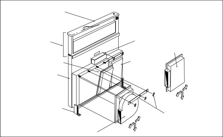
Figure 1
Top Cap
Snorkel |
J Box (electrical |
|
|
Connections) |
Duct Transition |
||
|
|||
|
|
||
|
|
to Remote Blower |
|
"Clean out" area |
Access Panel |
|
Ventilator Intake
Support Leg
Channel Clamp
and Wing Nuts
Integral Blower
INTRODUCTION
GENERAL DESCRIPTION
The complete Universal Cook‘n‘Vent ®
System consists of the ventilator intake and a blower. See Fig. 1. The blower is either an integral (mounted on the vent intake in the cabinet under the cooktop) or a remote (roof or outside wall mounted). When a remote blower is used, a duct transition is mounted on the ventilator intake in place of the integral blower to connect the intake to the ductwork. The duct transition must be purchased separately.
The integral blower or duct transition can be mounted in different positions on the intake to route ductwork to avoid cabinet, building framing, utilities, etc. Important: To allow for cleaning access, locate blower in the position closest to the duct outlet.
The Universal Cook‘n’Vent® System is available in 30inch, 36-inch and 45-inch models, with countertop trim in either stainless, black, or white. It is intended for use with any residential 30-inch, 36-inch or 45-inch model (Thermador or other) gas or electric cooktop. It is not intended to be used with any professional style cooktop or range.
STEP 1
PLAN THE INSTALLATION
Carefully follow the planning procedures listed below. See Figure 2.
A.Determine whether a remote or integral blower will be used. Remote blower installation requires 4 wires plus a ground wire to run from the Cook‘n’Vent ® to the blower.
B.Make sure adequate cabinet and counter space has been provided for unit service if required.
C.Minimize cross drafts created by adjacent open windows, doors, air conditioning, old heating vents, recessed ceiling lights, and traffic patterns which may affect performance.
D.For gas cooktop installations make sure that a minimum 10 square inch opening is provided in the toekick or other cabinet area. Inadequate ventilation of the cabinet below the cooktop may result in flame outage when operating the vent system.
E.Provide "make-up air" to installation location to improve performance and prevent problems, such as fireplace chimney downdrafts.
F.Investigate potential ductwork routes and choose the shortest possible route from the unit to an outside wall
Page 2
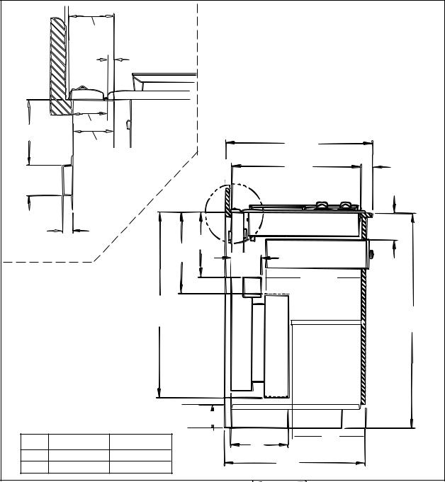
1/8" Min. |
|
2-3/8"
1/4"
Cooktop
1-3/4"
3-1/16"
2-1/16"
1-5/8"
Vent
Figure 2
•Be certain to avoid interferance with gas and electric supply to cooktop.
•Shelving and drawer depths are dependent upon cooktop depth and setback.
25"
Cutout |
SB (See |
|
Depth |
||
Fig. 7,8) |
9/16"
† 10" 12-3/4"
** For integral ventilator installations discharged
through left side of cabi- **
31" †
net, this dimension is 32-1/8".This installation requires a nonstandard cabinet for clearance.
†Dimensions are depen-
dent on discharge di-
rection. |
5" Max. |
|
|
||
|
INTEGRAL |
REMOTE |
A |
9-13/16" |
8-1/16" |
B |
13" |
15" |
|
Cooktop |
See Cooktop |
|
|
Installation |
5-3/4" |
Drawer |
|
|
|
|
|
17" Max. |
|
|
Shelving Must |
|
|
Be Removable |
36" |
|
|
|
Vent |
|
|
|
B |
A
24"
or roof. For guidance, typical ducting installations are shown in figures 3 through 6.
G.Determine whether the chosen route of ducting will meet vent system performance requirements. To do this, measure the duct lengths needed and determine specific fittings required. Enter this data in the spaces provided in Table 1. The total equivalent length of duct used must not exceed 85 feet with integral
blower, or 70 feet with remote blower. If the initial calculation exceeds this limit, replan the installation by reducing the number of fittings, increasing duct sizes, shortening duct lengths, etc., until this important requirement is met.
H.Follow the duct installation guidelines in Table 2.
Page 3

FIGURES 3 THROUGH 6 ARE EXAMPLES OF POSSIBLE DUCTING
Figure 3
REMOTE BLOWER
Remote
Blower
Duct Attachment Box CVD310 or CVD314
ROOF MOUNT INSTALLATION
Figure 4
INTEGRAL BLOWER
VTN600CVR
Wall Cap 1255-1
12" Min.
Ground
THROUGH WALL INSTALLATION
Figure 5
INTEGRAL BLOWER
VTN600CVR
BLOWER ROTATED 90° FOR SIDE
CONNECTION
THROUGH WALL DUCT INSTALLATION
Figure 6
REMOTE BLOWER
3-1/4" x 10" or 14" Duct End Must Be Closed and Sealed
Remote Blower |
Duct Attachment |
|
Box CVD310 or |
||
|
||
|
CVD314 |
|
|
10" Collar |
THROUGH WALL INSTALLATION
Page 4
 Loading...