

Page 1
“DRV830x-HC-C2-KIT” How to Run Guide
Version 1.0 August 2011 - TIDU396
This Guide explains the steps needed to run the DRV830x-HC-C2-KIT with the software supplied
through controlSUITE. This guide pertains to either the DRV8301-HC-EVM or the DRV8302-HCEVM. The software is located at:
controlSUITE\developement_kits\DRV830x-HC-C2-KITv*\
The following projects are currently available for the kit:
- Fixed/Floating point projects based on Piccolo (TMS320F2803x or TMS320F2806x, using v3.1
DMCLib)
• PM_Sensorless: Sensorless Field Oriented Control of Permanent Magnet Motor
• BLDC_Int: Sensorless Trapezoidal Control of BLDC Motors based on BEMF Integration
The document assumes the user has read the Kit’s Hardware Reference Guide and understood all
the safety measures that need to be taken. The guide is found under
controlSUITE\developement_kits\DRV830x-HC-C2-KITv*\~Docs\
C2000 Systems and Applications Team
WARNING
This EVM is meant to be operated in a lab environment only and is not
nsidered by TI to be a finished end-product fit for general consumer use.
co
This EVM must be used only by qualified engineers and technicians familiar
with risks associated with handling high voltage electrical and
mechanical components, systems and subsystems.
This equipment operates at voltages and currents that can result in electrical
shock, fire hazard and/or personal injury if not properly handled or applied. Equipment must
be used with necessary caution and appropriate safeguards must be employed to avoid
personal injury or property damage.
It is the user’s responsibility to confirm that the voltages are identified and understood, prior
to energizing the board and or simulation. When energized, the EVM or components
connected to the EVM should not be touched.
Page 2

Hardware Configuration
To experiment with digital motor control the following hardware components are needed:
DRV830x-HC-EVM
TMS320F28035 controlCARD;
PMSM or BLDC Motor
PC with Code Composer Studio (CCSv4) installed
Additional instruments such as oscilloscope, digital multi-meter, current sensing probe and function
generator.
A high voltage DC power supply (Up to 60V DC)
The experimental setup and connection are illustrated in the following section. Refer to the Hardware
Guide and DRV830x-HC-EVM schematic file for detailed configuration of each component and
connection of the system in detail.
Note: Keep all the power supplies to zero unless directed to energize.
There are two main power domains on the DRV830x-HC-EVM platform:
1) Controller Power Domain which provides the 5V and 3.3V for the microcontroller, the logic and
the sensing circuit present on the board.
2) DC Bus Power is the high voltage line that provides the voltage to the DRV830x chip to generate
the power to the motor. The DC Bus is provided by an external DC power supply connected to the
PVDD and GND terminals. (Max 60V DC)
Page 3
Motor Control Experiment HW Setup Instructions
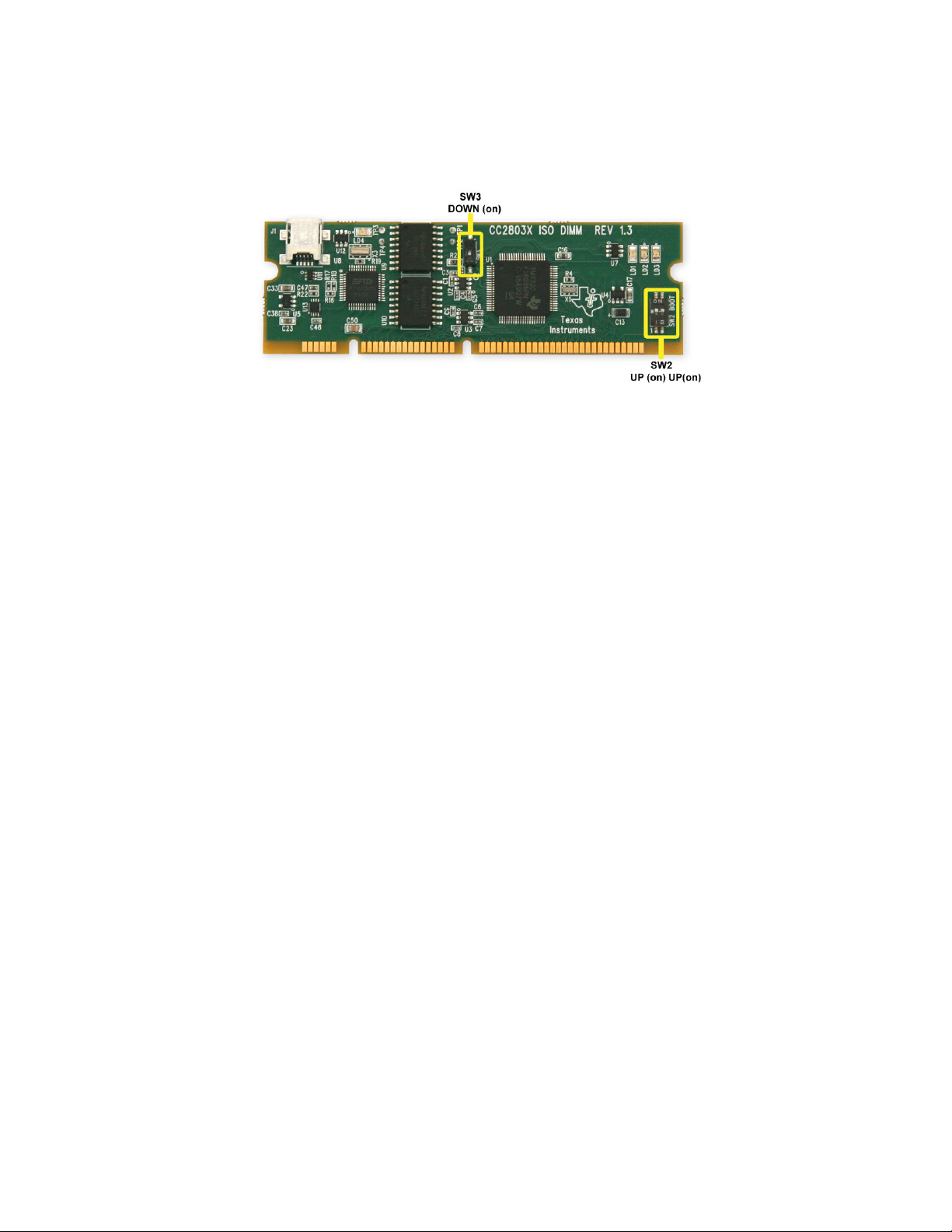
Unpack the DIMM style controlCARD and verify that the DIP switch settings match Figure 1.
Figure 1 controlCARD DIP Switch Settings
1. Place the controlCARD in the connector slot of J1. Push vertically down using even pressure from
both ends of the card until the clips snap and lock. (to remove the card simply spread open the
retaining clip with thumbs)
2. Connect a USB cable to J1 on the controlCARD. This will enable isolated JTAG emulation to the
C2000 device. LD4 on the controlCARD should turn on.
3. Connect a 8-60V DC power supply to the PVDD and GND terminals of the DRV830x-HC-EVM.
Now LED1 and LED3 should turn on. Notice the control card LED would light up as well indicating
the control card is receiving power from the board.
4. Note that the motor should be connected to the OUT A, OUT B and OUT C terminals after you
finish with the first incremental build step.
Page 4
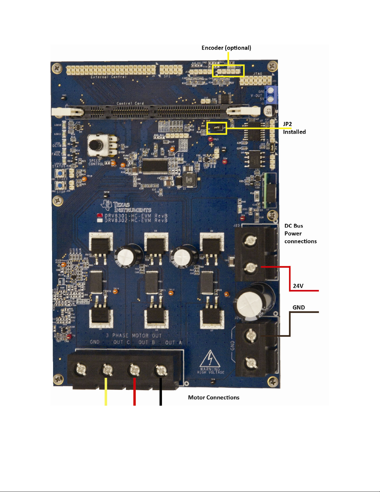
Figure 2 Hardware Setup for PM_Sensorless Experiment
Page 5
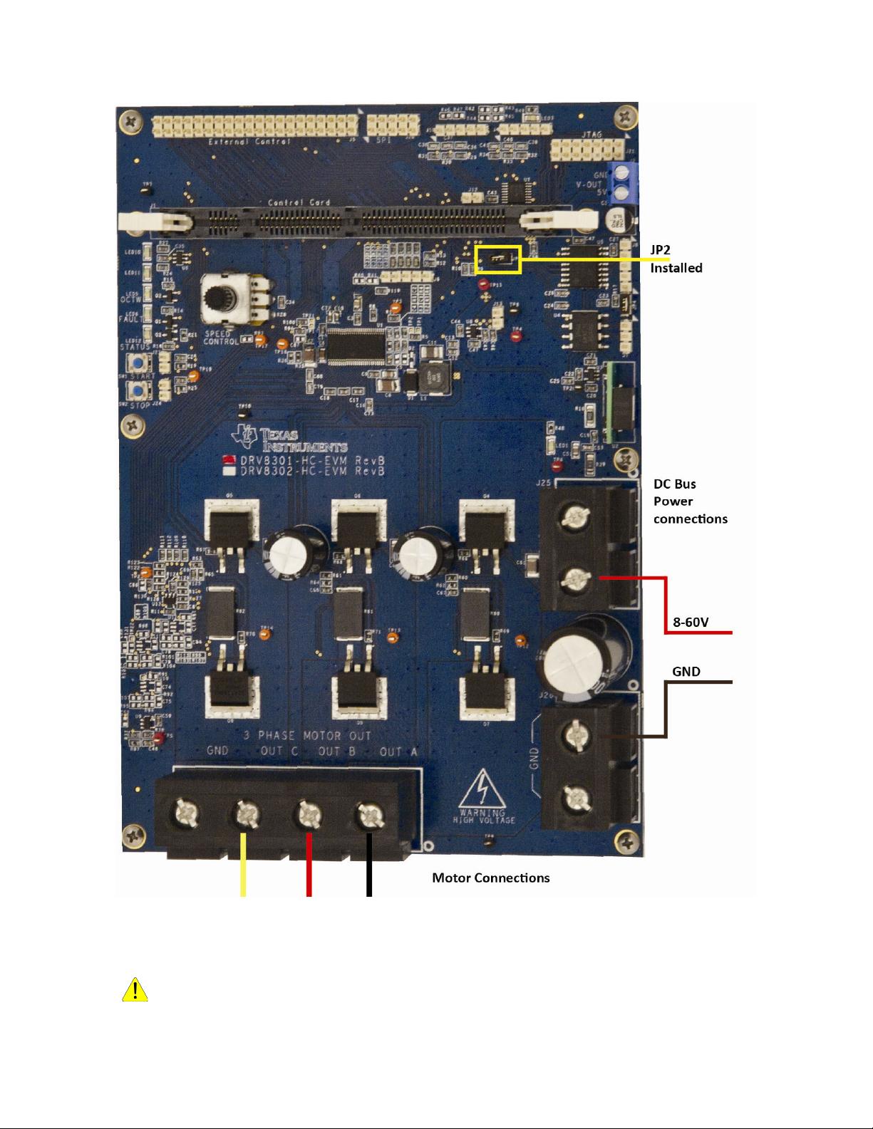
Figure 3 Hardware Setup for BLDC_Sensored and BLDC_Sensorless Experiments
WARNING: DC bus Capacitors would remain charged for a long time after the supply is
isconnected. Use caution!
d
Page 6

Software Setup for DRV8301-HC-C2-KIT Projects
Installing Code Composer and controlSUITE
1. If not already installed, please install Code Composer v4.x from the DVD included with the kit.
2. Go to http://www.ti.com/controlsuite
“DRV830x-HC-C2-KIT” software and allow the installer to also download all automatically
checked software.
Setup Code Composer Studio to Work with the DRV830x-HC-C2-KIT
3. Open “Code Composer Studio v4”.
4. Once Code Composer Studio opens, the workspace launcher may appear that would ask to
select a workspace location,: (please note workspace is a location on the hard drive where
all the user settings for the IDE i.e. which projects are open, what configuration is selected
etc. are saved, this can be anywhere on the disk, the location mentioned below is just for
reference. Also note that if this is not your first-time running Code Composer this dialog may
not appear)
Click the “Browse…” button
Create the path below by making new folders as necessary.
“C:\Documents and Settings\My Documents\ CCSv4_workspaces\DRV830x-HC-
EVM_workspace”
and run the controlSUITE installer. Select to install the
Uncheck the box that says “Use this as the default and do not ask again”.
Click “OK”
Figure 4 Workspace Launcher
5. Next we will configure Code Composer to know which MCU it will be connecting to. Click
“Target -> New Target Configuration…”. Name the new configuration xds100-f28035.ccxml
or any other name depending on the target device. Make sure that the “Use shared location”
checkbox is checked and then click Finish.
Page 7
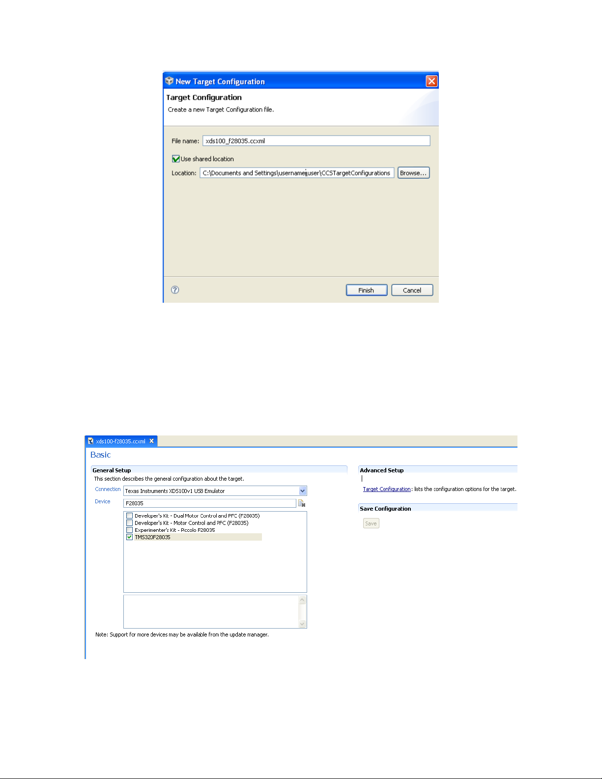
Figure 5 Creating a target configuration
6. This should open up a new tab as seen in Figure 6. Select and enter the options as shown:
Connection – Texas Instruments XDS100v1 USB Emulator
Device – TMS320F28035
Click Save
Close the xds100-f28035.ccxml tab
Figure 6 Configuring a new target
Page 8

7. Assuming this is your first time using Code Composer, the configuration is now set as the
default target configuration for Code Composer. Please check this by going to“View->Target
Configurations”. In the “User Defined” section, right-click on the xds100-F28035.ccxml file
and select “Set as Default”. This tab also allows you to reuse existing target configurations
and link them to specific projects.
8. Add all the motor control projects into your current workspace by clicking “Project->Import
Existing CCS/CCE Eclipse Project”.
Select the root directory of the DRV830x-HC-C2-KIT. This will be:
“controlSUITE\development_kits\DRV830x-HC-C2-KITv*\”
Figure 7 Adding all DRV830x-HC-C2-KIT projects to your workspace
Click Finish, this would copy all the projects relevant for the kit into the workspace. If you
want only a particular project to be copied uncheck the box next to the other project
names.
Page 9

Configuring a Project
9. Expand the file structure of the project you would like to run from the C/C++ Projects tab.
Right-click on this project’s name and select “Set as Active Project”.
10. Assuming this is your first time using Code Composer, the xds100-F28035 should have been
set as the default target configuration. Do verify this by viewing the xds100-f28035.ccxml file
in the expanded project structure and a [Active/Default] written next to it. By going to “View->
Target Configurations” you may edit existing target configurations or change the default or
active configuration. You can also link a target configuration to a project in the workspace by
right clicking on the Target configuration name and selecting Link to Project.
11. Each project has multiple build configurations to support different target MCUs or different
DRV83xx base boards. You will need to select the build configuration that matches your
hardware setup. As an example Figure 8 shows selection of the DRV8301-HC-EVM with a
2803x MCU. Right-click on an individual project and select Active Build Configuration->
F
DRV8301_F2803x_RAM configuration.
Figure 8 Selecting the DRV8301_F2803x_RAM configuration
Build and Load the Project
12. The TI motor control software is provided with incremental builds where different components
/ macro blocks of the system are pieced together one by one to form the entire system. This
helps in step by step debug and understanding of the system. From the C/C++ Project tab
open the file [Project-Name]-Settings.h and make sure that BUILDLEVEL is set to LEVEL1
and save this file. After we test build 1, this variable will need to be redefined to move on to
build 2, and so on until all builds are complete.
Page 10

13. Open and inspect [Project-Name] -DevInit_F2803x.c by double clicking on the filename in the
project window. Confirm that GPIO00 to GPIO05 are configured to be PWM outputs.
14. Open the [Project-Name].c file and go to the function MainISR(). Locate the following piece of
code in incremental build 1 and confirm that the Datalog buffers are pointing to the right
variables. These Datalog buffers are large arrays that contain value-triggered data that can
then be displayed to a graph. Note that in other incremental builds different variables may be
put into this buffer to be graphed. Following is an example where the datalog are pointed to
the PID module.
DlogCh1 = (int16)_IQtoIQ15(pid1_i.Ref);
DlogCh2 = (int16)_IQtoIQ15(pid1_i.Fdb);
DlogCh3 = (int16)_IQtoIQ15(pid2_i.Ref);
DlogCh4 = (int16)_IQtoIQ15(pid2_i.Fdb);
15. Now Right Click on the Project Name and click on “Rebuild Project” and watch the Console
window. Any errors in the project will be displayed in the Console window.
16. On successful completion of the build click the
of the screen. The IDE will now automatically connect to the target, load the output file into
the device and change to the Debug perspective.
17. Click “Tools->Debugger Options->Generic Debugger Options”. You can enable the debugger
to reset the processor each time it reloads program by checking “Reset the target on program
load or restart” and click “Remember My Settings” to make this setting permanent.
18. Now click on the “Enable silicon real-time mode” button and “Enable polite real-time
mode” button . This will allow the user to edit and view variables in real-time. Do not reset
the CPU without disabling these realtime options!
19. A message box may appear. If so, select YES to enable debug events. This will set bit 1
(DGBM bit) of status register 1 (ST1) to a “0”. The DGBM is the debug enable mask bit.
When the DGBM bit is set to “0”, memory and register values can be passed to the host
processor for updating the debugger windows.
“Debug” button, located in the top-left side
Page 11

Setup Watch Window & Graphs
Click: View Watch on the menu bar to open a watch window to view the variables being used in
the project. Add variables to the watch window as shown below. By right-clicking on the variable it is
possible to change the number format of the variable. Refer to the project specific document to know
what variables need to be added to the watch window. You can select the appropriate Q format for
the variable you want to watch. Figure 9 below shows a typical watch window.
Within each project folder is a CCS Java Script file that can automatically populate a watch window
with some default variables. Select View->Scripting Console to open the Java Scripting Console.
Next, in the Scripting Console window, click the open folder and browse to the project folder.
controlSUITE\developement_kits\DRV830x-HC-C2-KITv*\<project directory>
Select the AddWatchWindowVars_F280xx.js file that corresponds to your target MCU.
Figure 9 Configuring the Watch Window for) fixed point devices
20. Click on the Continuous Refresh button in the watch window. This enables the window to
run with real-time mode. By clicking the down arrow in this watch window, you may select
“Customize Continuous Refresh Interval” and edit the refresh rate of the watch window. Note
that choosing too fast an interval may affect performance.
21. The datalog buffers point to different system variables depending on the build level. They
provide a means to visually inspect the variables and judge system performance. Open and
setup time graph windows to plot the data log buffers as shown below. Alternatively, the user
can import graph configurations files in the project folder; however, these files are not
supported by all CCS4 versions. In order to import them, Click: Tools -> Graph ->
DualTime… and select import and browse to the following location
controlSUITE\developement_kits\DRV830x-HC-C2-KITv*.*\<project directory> and select
Graph1.graphProp, the Graph Properties window should now look like the Figure 10. Hit OK,
is should add the Graphs to your debug perspective. Click on Continuous Refresh button
th
on the top left corner of the graph tab.
Page 12

Note: If a second graph window is used, you could import Graph2.prop, the start Addresses
for this should be DLOG_4CH_buff3 and DLOG_4CH_buff4.
Note: The default dlog.prescaler is set to 5 which will allow the dlog function to only log one
out of every five samples.
Figure 10 Graph window settings
Run the Code
22. Run the code by pressing Run Button in the Debug Tab.
23. The project should now run, and the values in the graphs and watch window should keep on
updating. Below are some screen captures of typical CCS perspective while using this
project, You may want to resize the windows according to your preference.
24. Once complete, reset the processor (Target->Reset->Reset CPU) and then terminate
the debug session by clicking (Target->Terminate All). This will halt the program and
disconnect Code Composer from the MCU.
Page 13

Project Files
Project Files
Motor Control Code
Motor Control Code
C/C++
C/C++
Perspective
Perspective
CCS v4 C/C++
Perspective
Debug
Debug
View
View
Window
Window
view CPU’s
view CPU’s
being
being
Debugged
Debugged
currently
currently
Console window to display
Console window to display
Build progress / Errors
Build progress / Errors
Disassembly window
Disassembly window
Shows location in code
Shows location in code
when stepping through debugger
when stepping through debugger
Set Real Time mode
Set Real Time mode
Summary of all the Build
Summary of all the Build
Errors and warnings go here
Errors and warnings go here
Debug
Debug
Perspective
Perspective
Real-time
Real-time
variable
variable
Watch
Watch
Window
Window
CCSv4 Debug
Perspective
Real-time
Real-time
Graph
Graph
Window
Window
Page 14

Next Steps
25. It is not necessary to terminate the debug session each time the user changes or runs the
code again. Instead the following procedure can be followed. After rebuilding the project,
(Target->Reset->Reset CPU) , (Target->Reset->Restart ) , and enable realtime options.
Once complete, disable realtime options, and reset CPU. Terminate the project if the target
device or the configuration is changed (Ram to Flash or Flash to Ram), and before shutting
down CCS.
26. Customize the project to meet your motor. Change the motor parameters which can be found
in [motorproject].h. Feel free to also change the PWM switching frequency (ISR frequency)
and the base Q-value to balance accuracy and CPU bandwidth.
27. Now the user can open the lab manual found in : controlSUITE\development_kits\DRV830xHC-C2-KITv*\[Project-Name]\~Docs and start experiments.
Page 15

IMPORTANT NOTICE
Texas Instruments Incorporated and its subsidiaries (TI) reserve the right to make corrections, enhancements, improvements and other
changes to its semiconductor products and services per JESD46, latest issue, and to discontinue any product or service per JESD48, latest
issue. Buyers should obtain the latest relevant information before placing orders and should verify that such information is current and
complete. All semiconductor products (also referred to herein as “components”) are sold subject to TI’s terms and conditions of sale
supplied at the time of order acknowledgment.
TI warrants performance of its components to the specifications applicable at the time of sale, in accordance with the warranty in TI’s terms
and conditions of sale of semiconductor products. Testing and other quality control techniques are used to the extent TI deems necessary
to support this warranty. Except where mandated by applicable law, testing of all parameters of each component is not necessarily
performed.
TI assumes no liability for applications assistance or the design of Buyers’ products. Buyers are responsible for their products and
applications using TI components. To minimize the risks associated with Buyers’ products and applications, Buyers should provide
adequate design and operating safeguards.
TI does not warrant or represent that any license, either express or implied, is granted under any patent right, copyright, mask work right, or
other intellectual property right relating to any combination, machine, or process in which TI components or services are used. Information
published by TI regarding third-party products or services does not constitute a license to use such products or services or a warranty or
endorsement thereof. Use of such information may require a license from a third party under the patents or other intellectual property of the
third party, or a license from TI under the patents or other intellectual property of TI.
Reproduction of significant portions of TI information in TI data books or data sheets is permissible only if reproduction is without alteration
and is accompanied by all associated warranties, conditions, limitations, and notices. TI is not responsible or liable for such altered
documentation. Information of third parties may be subject to additional restrictions.
Resale of TI components or services with statements different from or beyond the parameters stated by TI for that component or service
voids all express and any implied warranties for the associated TI component or service and is an unfair and deceptive business practice.
TI is not responsible or liable for any such statements.
Buyer acknowledges and agrees that it is solely responsible for compliance with all legal, regulatory and safety-related requirements
concerning its products, and any use of TI components in its applications, notwithstanding any applications-related information or support
that may be provided by TI. Buyer represents and agrees that it has all the necessary expertise to create and implement safeguards which
anticipate dangerous consequences of failures, monitor failures and their consequences, lessen the likelihood of failures that might cause
harm and take appropriate remedial actions. Buyer will fully indemnify TI and its representatives against any damages arising out of the use
of any TI components in safety-critical applications.
In some cases, TI components may be promoted specifically to facilitate safety-related applications. With such components, TI’s goal is to
help enable customers to design and create their own end-product solutions that meet applicable functional safety standards and
requirements. Nonetheless, such components are subject to these terms.
No TI components are authorized for use in FDA Class III (or similar life-critical medical equipment) unless authorized officers of the parties
have executed a special agreement specifically governing such use.
Only those TI components which TI has specifically designated as military grade or “enhanced plastic” are designed and intended for use in
military/aerospace applications or environments. Buyer acknowledges and agrees that any military or aerospace use of TI components
which have not been so designated is solely at the Buyer's risk, and that Buyer is solely responsible for compliance with all legal and
regulatory requirements in connection with such use.
TI has specifically designated certain components as meeting ISO/TS16949 requirements, mainly for automotive use. In any case of use of
non-designated products, TI will not be responsible for any failure to meet ISO/TS16949.
Products Applications
Audio www.ti.com/audio Automotive and Transportation www.ti.com/automotive
Amplifiers amplifier.ti.com Communications and Telecom www.ti.com/communications
Data Converters dataconverter.ti.com Computers and Peripherals www.ti.com/computers
DLP® Products www.dlp.com Consumer Electronics www.ti.com/consumer-apps
DSP dsp.ti.com Energy and Lighting www.ti.com/energy
Clocks and Timers www.ti.com/clocks Industrial www.ti.com/industrial
Interface interface.ti.com Medical www.ti.com/medical
Logic logic.ti.com Security www.ti.com/security
Power Mgmt power.ti.com Space, Avionics and Defense www.ti.com/space-avionics-defense
Microcontrollers microcontroller.ti.com Video and Imaging www.ti.com/video
RFID www.ti-rfid.com
OMAP Applications Processors www.ti.com/omap TI E2E Community e2e.ti.com
Wireless Connectivity www.ti.com/wirelessconnectivity
Mailing Address: Texas Instruments, Post Office Box 655303, Dallas, Texas 75265
Copyright © 2015, Texas Instruments Incorporated
 Loading...