

Page 1

IO 18/E Rev. 00
OPERATORS FOR SWING GATES
STONE 300-400-600 GR / 220V
INSTALLATION MANUAL
Our compliments for your excellent choice. The STONE 300-400-600
GR electro-mechanical gear motor has been produced for reliability
and high quality.
This Manual will offer information you may need to install your gear
motor assuring long-lasting performance and to safeguard your safety.
HOWEVER CAUTION IS UNQUESTIONABLY INDISPENSABLE
AND NOTHING IS BETTER THAN PREVENTING ACCIDENTS.
GR products have been made to conform with rules and laws in force
at time of manufacture.
This manual is designed exclusively for the specialized
installation expert in the criteria of construction and equipment to
assist in the protection against accidents in the installation and use of
the gate; door and automation of such gates (adhere to the rules and
laws in force).
On completion the installer should issue to the end consumer an
instruction manual according to EN 12635.
Before proceeding with the installation the installer must provide
an analysis of the identification and management of risks as per the
standards EN 12453 and EN 12445.
All wiring of the various external electrical components
connected to the automation (e.g. Photocells, flashing lights, keypads
etc) must be carried out according to EN 60204-1 and the
amendments made of the point 5.2.2 of EN 12453.
It is prohibited to do any repair or adjustment of the equipment if
you have not taken all necessary precautions to avoid possible
accidents (example: power supply disconnected, engine block). All
mechanisms in motion must be equipped with appropriate protections.
The mains power line must be protected for maximum current in
locked rotor condition as per government electrical laws.
Install the gear motor on gates that conform to EN 12604.
Perform the measure of strength developed by the gear motor
and adopt the measures as per EN 12445.
Positioning photocells: These safety devices must be installed at
a height not exceeding 70cm from the ground and at a distance from
the floor movement of the door of no more than 20cm. Their proper
functioning of the photocells must be verified at the end of installation
according to Section 7.2.1 of EN12445.
Keep the activation controls of automation out of reach of
children. The controls should be installed at a minimum 1.5m height
above the ground and outside the range of actions of moving parts
such as the gate.
All activation actions must be executed only at points from
where the automation is fully visible.
Operate the remote only in view of automation.
Store carefully this manual in a suitable place known to all
interested people.
Any unauthorized and arbitrary modification made to this
product, releases the company CARDIN ELETTRONICA Spa and
from any liability resulting from damage or injury to things, people or
animals.
The non-observance of regulations and of safety standards here
listed releases the company CARDIN ELETTRONICA Spa from any
liability resulting from damage or injury to things, people or animals.
The automation must be coupled to a control board equipped
with torque regulation that provides an anti crushing safety as
described in EN 12453 - EN 12445
SAFETY RULES
During the installation and the use of the automation, pay attention to
the following safety rules:
Distance security!
Mechanisms moving!
Do not install automation in an environment saturated with
explosive mixtures!
Electric Shock!
Use gloves!
Use welding glasses!
Maintain ear protection!
MAINTENANCE
All repairs must be carried out by qualified people.
Before each intervention remove power through the switch and
lock in that position
The equipment must be maintained so as to preserve the
conditions that ensure safe and efficient operation
Always use original spare parts
Do not make interventions that modify the machine.
The modified equipment requires new CE mark
The settings of the operator must be performed by qualified
personnel, in accordance with the rules of reference. During these
operations provide the presence of two operators for safety.
Page 2
IO 18/E Rev. 00
DEMOLITION
You have to operate the elimination of the materials in conformity with
the regulations in force. All materials must be divided by type (copper,
aluminium, plastic, electrical parts, etc)
DISMANTLING
In order to move away the automation, follow these instructions:
1 - cut off the power supply and disconnect the electrical installation;
2 - dismantle the control console and all the other components of the
installation.
If you have noticed that some components have been damaged, you
have to replace them.
CONFORMITY DECLARATION:
It’s in accordance with Machine Directive 39/89/CE and following
modify.
It’s in accordance with the following directive CE:
Electromagnetic compatibility Directive 89/336/CEE and following
modify.
Low tension Directive 73/23/CEE and following modify.
Have been applied the following harmonized norms:
EN292/1/2, EN 294, EN60335-1, UNI EN 12453, and what applicable
of the EN12445-2000.
USE OF THE AUTOMATION
The gearmotor STONE 300-400-600 GR was designed and built for
the opening of gates with max of 5 m leaf or weight max. 200kg. The
CARDIN ELETTRONICA Spa assumes no responsibility for a purpose
other than that provided by gearmotor STONE 300-400-600 GR. Since
automation can be put into motion in view by button or remotely by
remote control, it is essential to check frequently the perfect efficiency
of all safety devices. It is advisable to check periodically (every six
months) the regulation of electronic friction of which must be equipped
the electronic control board.
PRELIMINARY CHECKS
1 - Read carefully the instructions enclosed in this manual.
2 - Make sure that the gate has a rather solid structure and that there
is no friction points in its movement.
3 - Make sure that the leaf is suitably balanced, even after the
installation of the gear motor.
4 - Check that the electrical installation is in accordance with the
characteristic required by the gear motor.
TECHINICAL DATA
SCHEDULED MAINTENANCE
DESCRIPTION
FREQUENCY
ENTRUSTED
OPERATION
Photocells cleaning
Monthly
Operator
Clean with damp cloth
Control of gate hinges and supports, balancing of the
gate
Annual
Operator
Check the status of welds and corrosion.
Unhook the engine and check the
balancing and the eventual points of
friction.
Controlling the sensitivity of electronic friction (torque
adjustment) of the control board.
Semiannual
Technician
Check the adjustment of the couple as
described in EN 12453 - EN 12445
Monitoring current dispersion
Annual
Technician
Verify that the dispersion of current is
less than 7.5 A
Control of signals
Semiannual
Operator
Verify that the safety warning signage is
complete and intact
EMERGENCY MANOEUVRE
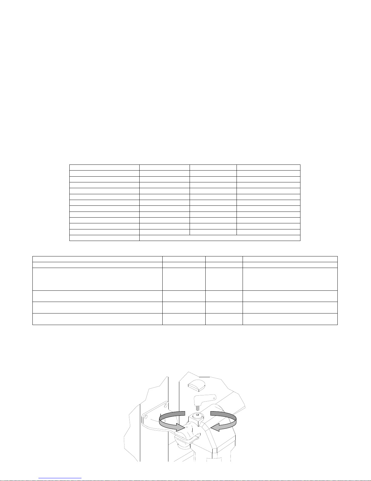
For the manual door locking and unlocking act with the supplied key on the screw C (See FIG 1-2).
1 - Remove the protection cap
2 - insert the key into the seat allocation as in Figure 1
3 - Turn the key in the sense of the arrow to the top of the gearmotor to unlock and in the opposite block.
STONE 300 GR
STONE 400 GR
STONE 600 GR
Maximum length of the gate
3,0m
4,0 m
5,0 m
Maximum weight of the gate
200Kg
200Kg
200Kg
Stroche
30cm
40cm
60cm
Power
180 W
180 W
180 W
Power supply
220 V
220 V
220V
Absorption
0,9 A
0,9 A
0,9 A
Max. Thrust
1600 N
1600 N
1600 N
Operating temperature
-25°C +60°C
-25°C +60°C
-25°C +60°C
Opening time
17sec.
22sec.
33sec.
Thermal protection
150°C
150°C
150°C
Use frequency
35%
35%
35%
Lubrication
GREASE
ANTICLOCKWISE:
RELEASED
CLOCKWISE:
BLOCKED
FIG 1
Page 3
IO 18/E Rev. 00
INSTALLATION
INSTALLATION
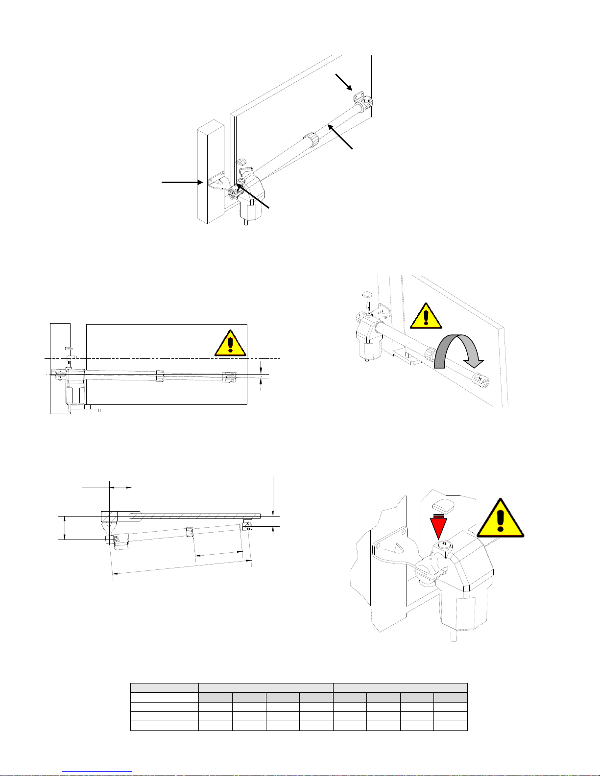
To operate a good installation of the gear motors STONE 300-400-600
GR, follow these instructions:
1 - Open the box and take out gear motor. Make sure that it has not
been damaged during the transport.
2 - Make sure that the leaf of the gate is perfectly horizontal.
3 - Place the gear motor inclined approximately 1º below the
horizontal line(picture 3 )
1°
4- Fix the support plate A on the pillar beside the leaf, taking in account
the measures shown in Table 1. Do not forget inclination.
1°
Z
W
6.0
Y
X
5 - Install the gear motor on to the support plate A and fix it with the bolt.
6 - With gate’s leaf closed, turn and slide the screw of gear motor’s D
shaft, until the end of the stroke-
7 - Screw D shaft back on 1 complete turn of 360º. (picture5)
8 - Place B support plate in the hole of D shaft and position it against
the gate leaf. Fix it to the gate leaf taking in account the inclination
(point nr.3).
9 - Proceed in the same way with the other gate leaf.
10 - Connect the electrical wires and safety devices: Place the
mechanical limit stops
11 – Place the cover on the unblocking screw (C) (picture 6)
TAB 1
MOTOR
ROTATION 95 °
ROTATION 120 °
W X Y Z W X Y Z
STONE300
922
140
140
378
922
160
120
378
STONE400
1122
145
145
478
1122
170
110
478
STONE600
1532
280
280
678
1532
310
120
678
A
A – Pillar bracket
B – Gate bracket
D – Piston rod
C – Release
FIG 2
360°
FIG 3
FIG 4
FIG 5
FIG 6
Page 4
IO 18/E Rev. 00
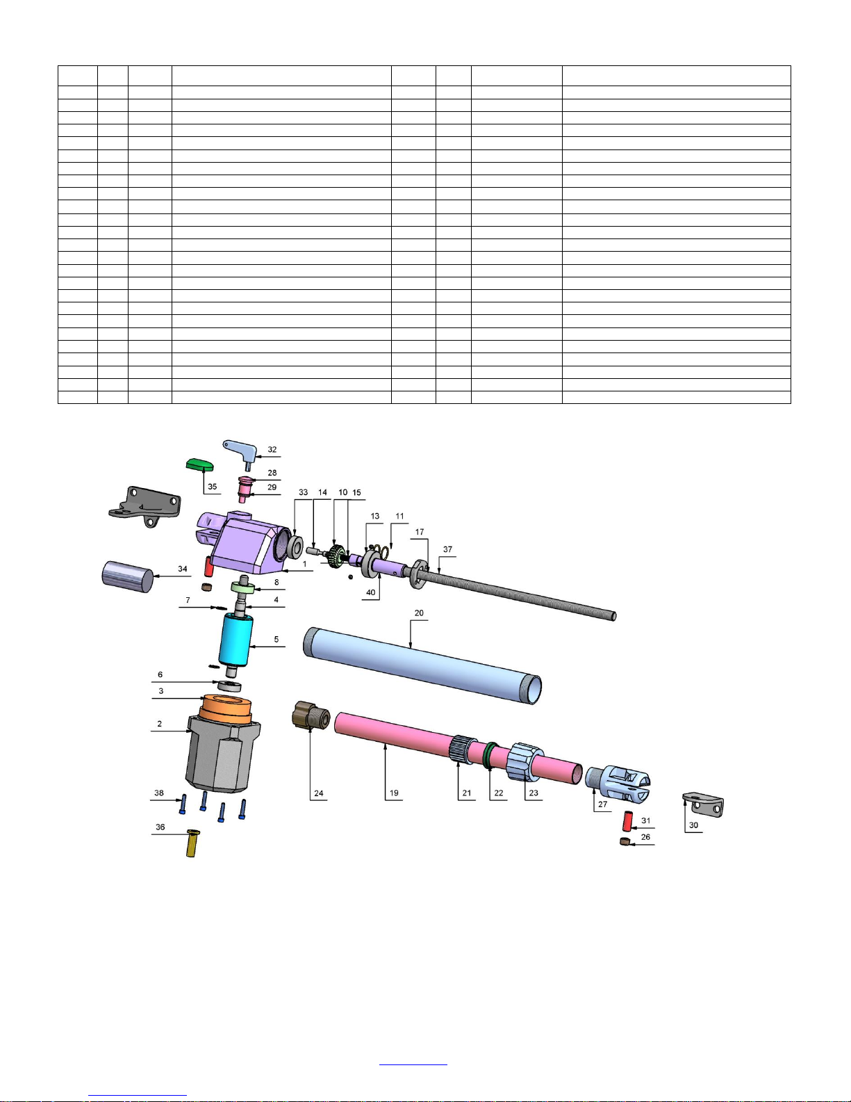
SPARE PARTS
PART
QTy
CODE
DESCRIPTION
PART
Q.TY
CODE
DESCRIPTION
1 1 100645
REDUCTION GEAR COVER LF. BLACK
20 1 100715
BLACK ALUMINIUM TUBE 400mm STROKE
1 1 100644
REDUCTION GEAR COVER RG. BLACK
20 1 100763
GREY ALUMINIUM TUBE 400mm STROKE
1 1 100759
REDUCTION GEAR COVER LF. GREY
20 1 100739
BLACK ALUMINIUM TUBE 600mm STROKE
1 1 100758
REDUCTION GEAR COVER RG. GREY
20 1 100764
GREY ALUMINIUM TUBE 600mm STROKE
2 1 100647
MOTOR CASING RG. BLACK
21 1 100829
PISTON ROD GUIDE
2 1 100761
MOTOR CASING RG. GREY
22 1 100625
SCRAPER RING
3 1 100840
STATOR 220V 4 POLES 45mm 1400rpm
23 1 100827
PISTON ROD LOCK NUT
4 1 100651
IRREVERSIBLE MOTOR SHAFT
24 1 100828
FEMALE SCREW
5 1 100841
ROTOR 45mm
25 1 100823
WALL BRACKET
6 1 100278
BEARING 6202 ZZ
26 2 100705
GRUB SCREW M14X10
7 2 100706
HELASTIC RING E15
27 1 100646
ALUMINIUM PISTON ROD TERMINAL BLACK
8 1 100291
BEARING 6202 2RS
27 1 100906
ALUMINIUM PISTON ROD TERMINAL GREY
10 1 100650
IRREVERSIBLE TOOTH WHEEL
28 1 100624
ALUMINIUM UNCLAMPING
11 2 100789
HELASTIC RING E20
29 2 100657
O-RING
12 1 100709
BEARING 6004 ZZ
30 1 100825
GATE BRACKET
13 2 100658
TOWING BALL
31 2 100654
PIN
14 1 100655
UNCLAMPING PIN
32 1 100218
UNCLAMPING KEY
15 1 100641
UNCLAMPING SPRING
33 1 100707
BEARING 6003 ZZ
17 1 100661
ALUMINIUM LOCK NUT
34 1 100184
CAPACITOR 8µF
17 100909
FIBRE LOCK NUT
35 1 100755
UNCLAMPING CAP
19 1 100712
STAINLESS STEEL TUBE 300mm STROKE
36 1 100748
CABLE PRESS
19 1 100713
STAINLESS STEEL TUBE 400mm STROKE
37 + 40
1
100716 + 100998
ENDLESS SCREW 40 + release shaft
19 1 100738
STAINLESS STEEL TUBE 600mm STROKE
37 + 40
1
100717 + 100998
ENDLESS SCREW 50 + release shaft
20 1 100714
BLACK ALUMINIUM TUBE 300mm STROKE
37 + 40
1
100740 + 100998
ENDLESS SCREW 70 + release shaft
20 1 100762
GREY ALUMINIUM TUBE 300mm STROKE
38 4 100313
CAP SCREW M5X16
CARDIN ELETTRONICA Spa
Via Del Lavoro, 73
31013 Codognè, Fraz. Cimavilla TV
Tel. +39 0438 404011 Fax. +39 0438 401831
www.cardin.it
Page 5

1
ZVL933.00 Mod: 12-05-2016
ITALIANO
ENGLISH
FRANÇAIS
DEUTSCH
ESPAÑOL
ATTENTION! Before installing this device read the
following instructions carefully!
Conformity declaration Page 2
Important remarks Page 8
Electrical connection Pages 8-9
Programming procedure Pages 10-11
Remote control Page 12
Function modes Page 12
Indications on the display Page 12
Technical specications Page 28
ATTENTION! Avant de commencer la pose, lire attentivement les instructions!
Déclaration de conformité Page 2
Consignes importantes Page 13
Branchement électrique Pages 13-14
Procédé de programmation Pages 15-16
Commande via radio Page 17
Modes de fonctionnement Page 17
Indications de l’afcheur Page 17
Caractéristiques techniques Page 28
ACHTUNG! Bevor mit der Installation begonnen wird,
sollte die Anleitung aufmerksam gelesen werden.
Konformitätserklarung Seite 2
Wichtige Hinweise Seite 18
Elektrischer Anschluss Seiten 18-19
Programmierverfahren Seiten 20-21
Funkbefehl Seite 22
Betriebsmodus Seite 22
Displayanzeigen Seite 22
Technische Eigenschaften Seite 28
¡ATENCIÓN! Antes de iniciar la instalación del sistema,
leer atentamente las instrucciones.
Declaración de conformidad Página 2
Advertencias importantes Página 23
Conexionado eléctrico Páginas 23-24
Procedimiento de programación Página 25-26
Mando vía radio Página 27
Modalidad de funcionamiento Página 27
Indicaciones en el display Página 27
Datos técnicas Página 28
ATTENZIONE! Prima di iniziare l'installazione leggere
le istruzioni attentamente!
Dichiarazione di conformità Pagina 2
Avvertenze importanti Pagina 3
Collegamento elettrico Pagine 3-4
Procedura di programmazione Pagine 5-6
Comando via radio Pagina 7
Modalità di funzionamento Pagina 7
Indicazioni del display Pagina 7
Caratteristiche tecniche Pagina 28
230 Vac Motors
PROGRAMMATORE ELETTRONICO PER IL COMANDO DI PORTE E PORTONI MOTORIZZATI
ELECTRONIC PROGRAMMER CONTROLLING MOTORISED GATES AND DOORS
PROGRAMMATEUR ÉLECTRONIQUE POUR LA COMMANDE DE PORTES ET PORTAILS MOTORISÉS
ELEKTRONISCHER STEUERUNGSEINHEIT FÜR DIE AUTOMATISIERUNG VON TÜREN UND TOREN
PROGRAMADOR ELECTRONICO PARA EL CONTROL DE LAS PUERTAS MOTORIZADAS
Questo prodotto è stato testato e collaudato nei laboratori della casa costruttrice, la quale ne ha verificato la
perfetta corrispondenza delle caratteristiche con quelle richieste dalla normativa vigente. This product has been
tried and tested in the manufacturer's laboratory who have verified that the product conforms in every aspect to
the safety standards in force. Ce produit a été testé et essayé dans les laboratoires du fabriquant. Pour l'installer
suivre attentivement les instructions fournies. Dieses Produkt wurde in den Werkstätten der Herstellerfirma
auf die perfekte Übereinstimmung ihrer Eigenschaften mit den von den geltenden Normen vorgeschriebenen
getestet und geprüft. Este producto ha sido probado y ensayado en los laboratorios del fabricante, que ha
comprobado la perfecta correspondencia de sus características con las contempladas
por la normativa vigente.
Model
Date
Instruction manual
Series
PRG230M2
V0.2
01-04-2016
ZVL593.00
CARDIN ELETTRONICA spa
Via del lavoro, 73 – Z.I. Cimavilla
31013 Codognè (TV) Italy
Tel: +39/0438.404011
Fax: +39/0438.401831
email (Italian): [email protected]
email (Europe): [email protected]
Http: www.cardin.it
Page 6
V. 02.2017
ZVL601
CENTRALE COMANDO PER 1-2 MOTORI 230V
Istruzioni d’uso e di programmazione
CENTRALE DE COMMANDE POUR 1-2 MOTEURS 230V
Notice d'emploi et de programmation
CENTRAL DE MANDO PARA 1 O 2 MOTORES DE 230 V
Instrucciones de uso y programación
ELECTRONIC CONTROL UNIT FOR 1 or 2 230V-MOTORS
Programming and user instructions
STEUERZENTRALE FÜR 1-2 MOTOREN MIT 230V
Gebrauchs- und Programmierungsanweisungen
BESTURINGSKAST VOOR 1-2 230V MOTOREN
Gebruiksaanwijzing en programmeerinstructies
I
F
E
GB
D
NL
mod. T600
Page 7
1
2
28
29
P1 (P/P)
STOP*
PA
Spia
PC
P2 (PED)
Led
3 4 5 86 9 10
12
14
15
16
18
19
20
13
17
11
22 21232627 2425
7
Art. XXXOC2
Art. TAST 3F
30
32
31
MEMORIA
Fig. A Fig. B
1
7
Page 8
222
190
150
50
118
280
220
(mm)
8
Page 9
24V
24V
FT
12V
(0) (0)
Alimentazione ac
Ingressi comando e sicurezze
38
31
32 33
34
35 36
3720
40
21
41
16
22
42
17 23
43
18
24
44
19
28 29
30
Collegamenti M1
Collegamenti M2
US1*
Uscite 230V
M1
M2
M1
M2
Com. Com.
C
CAP. M1 CAP. M1
ENC. ENC.
Encoder
Encoder
Spia
LAMP.
Luce C.
AP APNOCH CH
NC
25
45
26
46
27
47
D D
D
D
6 7
8
9
10 11
12
13
3
3
4
4
5
5
2
1
BSC
BSC
BSC
BSA
BSA
Com. (0)
BSA
FT 1
FT 2
JOLLY 1*
JOLLY 2*
STOP
PEDONALE
APRE
CHIUDE
230V
50Hz
LINEA
ALIMENTAZIONE
F6,3A
(230V)
F2A
(24V)
8K2*
8K2*
8K2*
8K2*
39
Rx
ANT.
14
15
Com. (0)
PASSO/PASSO
230V
max.100W
230V
TR1
12024 14
0
Linea Alim.
230V 50Hz
mod. T600 mod. T600
Fig. C Fig. D
9
Page 10
24V
24V
FT
E.S.
12V
(0) (0)
Alimentazione ac
Ingressi
comando
e sicurezze
38
31
32 33
34
35 36
3720
40
21
41
16
22
42
17 23
43
18
24
44
19
28 29
30
Collegamenti M1
US1*
Uscite 230V
230V
max.100W
230V
max.100W
Collegamenti M2
M2
M1
Com. Com.
C
CAP. M1 CAP. M2
ENC. ENC.
Spia
LAMP.
Luce C.
AP APNOCH CH
NC
25
452646
27
47
D D
6 789
10 11
12
13
345
21
BSC
Com. (0)
1 2 3 4 5 6 7
BSA
FT 1
FT 2
FT 1
FT 2
J1*
J 2*
STP
PED
PA
PC
39
Rx
ANT.
Rx
ANT.
14
15
Com. (0)
P/P
P1 (P/P)
P2 (PED)
Linea Alim.
230V 50Hz
TX TX
RX RX
Couple of photocells
(VEDO 180)
Couple of photocells
(VEDO 180)
Con.
Con.
N
L
Key selector
(APRO)
0
21
2 1
M1 M2
F6,3A F2A
STOP P/P
nc
no
24V
10
Page 11
3 4 3 4
3 4
n.o.
(n.a.)
n.o.
(n.a.)
n.c. n.c.
n.o.
(n.a.)
n.o.
(n.a.)
n.o.
(n.a.)
n.o.
(n.a.)
n.c. n.c.n.c. n.c.
n.c.
n.c.
n.c.
FCA
FCA
FCA FCCFCC
FCC
FCAFCA
n.c.n.c.
n.c.
n.c.n.c.
M1
M1
M1 M2 M2
3 4
FT3
BSA BSABSC BSC
TX
RX
24V
Couple of photocells
(VEDO 180)
8,2K 8,2K
8,2K 8,2K
Fig. E
Fig. F
CARATTERISTICHE E DESCRIZIONE DELLE PARTI
Centrale per il comando e controllo di 1 o 2 motori (230V) per apri cancello, queste le principali funzioni e caratteristiche:
- uscite motore 230V con LIMITAZIONE DI COPPIA, RALLENTAMENTO e SOFT-START.
- DOPPIO INGRESSO per il controllo, diretto, di BORDI SENSIBILI DI SICUREZZA(8,2K)
- versatile nel controllo e limitazione del “movimento anta” tramite SENSORI ENCODER o TEMPO
- PROGRAMMAZIONE E DIAGNOSTICAEVOLUTAcon il nuovo PRG-Link (optional)
- filtro di rete e ingressi con isolamento ottico, per la PROTEZIONE DADISTURBI
- facile ESCLUSIONE DEGLI INGRESSI (sicurezza) NON UTILIZZATI.
VERIFICHE PRELIMINARI E AVVERTENZE IMPORTANTI SULL’INSTALLAZIONE
Prima di passare all' installazione si consiglia di verificare:
1. la solidità delle strutture esistenti (colonne, cerniere, ante) in relazione alle forze sviluppate dal motore.
2. che vi siano dei fermi meccanici di adeguata robustezza a fine apertura e fine chiusura delle ante.
3. l’assenza di attriti o laschi eccessivi nei sistemi ruote/rotaia inferiore e rulli/guida superiore.
4. sia stata esclusa l'eventuale serratura manuale.
5. lo stato di eventuali cavi elettrici già presenti nell'impianto.
Avvertenze importanti:
1. L'installazione dell'automazione deve essere eseguita a regola d'arte da personale qualificato avente i requisiti di legge e
fatta in conformità della direttiva macchine 98/37/CE e alle normative EN13241-1, EN 12453 e EN 12445.
2. Fare un'analisi dei rischi dell'automazione e di conseguenza adottare le sicurezze e le segnalazioni necessarie.
3. Installare i dispositivi di comando (ad esempio il selettore a chiave) in modo che l'utilizzatore non si trovi in una zona
pericolosa.
4. Applicare sull'automazione l'etichetta o la targhetta CE contenenti le informazioni di pericolo e idati di identificazione.
5. Consegnare all'utilizzatore finale le istruzioni d'uso, le avvertenze per la sicurezza e la dichiarazione CE di conformità.
6. Accertarsi che l'utilizzatore abbia compreso il corretto funzionamento automatico, manuale e di emergenza
dell'automazione.
7. Terminata l'installazione provare più volte i dispositivi di sicurezza, segnalazione e di sblocco dell'automazione.
8. Informare l'utilizzatore per iscritto (ad esempio nelle istruzioni d'uso):
a. Dell'eventuale presenza di rischi residui non protetti e dell'uso improprio prevedibile.
b. Di scollegare l'alimentazione prima di sbloccare l’anta o quando si eseguono piccole manutenzioni oppure durante la
c. Di controllare frequentemente che non vi siano danni visibili all'automazione e nel caso ve ne siano, avvertire
d. Di non far giocare i bambini nelle immediate vicinanze dell'automazione
e. Di mantenere i radiocomandi e altri dispositivi di comando fuori della portata dei bambini.
9. Predisporre un piano di manutenzione dell'impianto (almeno ogni 6 mesi) riportando su di un apposito registro gli interventi
eseguiti.
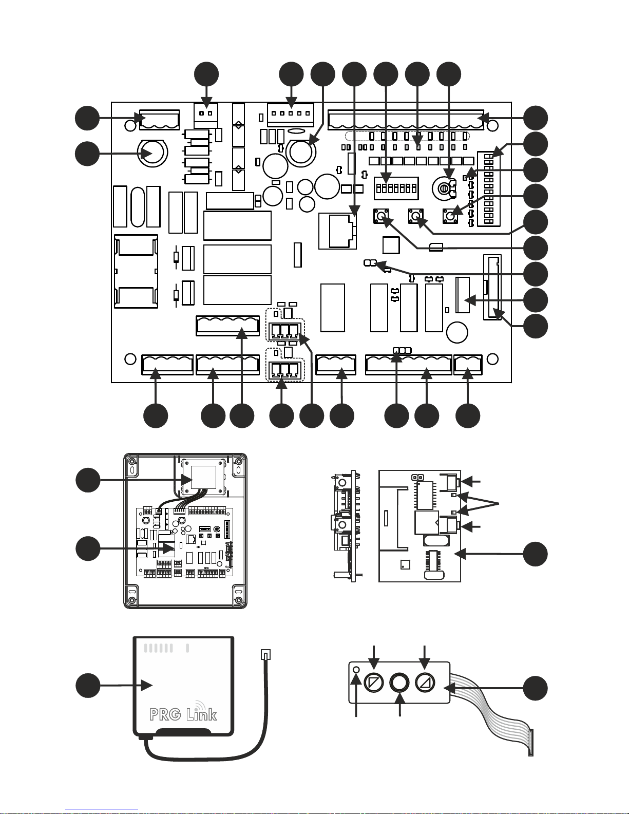
Descrizione delle parti (fig.A)
1. morsettiera ingresso alimentazione 230V
2. fusibile 6,3 Aper protezione linea 230V
3. morsettiera uscite 230V per lampeggiante e “luce di
cortesia”
4. morsettiera uscita 230V per motore M1
5. morsettiera uscita 230V per motore M2
6. morsettiera ingresso ENCODER M1
7. morsettiera ingresso ENCODER M2
8. morsettiera uscita contatto US1
9. jumper per alimentazione permanente fotocellule
10. morsettiera uscite ausiliari 12/24V
11. morsetto ingresso antenna ricevente OC2
12. connettore per ricevente OC2
13. connettore per tastiera TAST 3F
14. terminali per reset procedure in corso
15. tasto per PROGRAMMAZIONE e STOP
16. tasto P3
17. tasto PASSO/PASSO (P/P)
11
Page 12
CHARACTERISTICS AND COMPONENT DESCRIPTIONS
ECU for the command and control of 1 or 2 gate opening motors (230V).
The main characteristics are:
- 230V-motor output with TORQUE LIMITATION, DECELERATION and SOFT-START.
- TWO INPUTS for the direct control of SAFETY EDGES (8,2K)
- Versatile gate movement control and limitation using ENCODER or TIMER CONTROLLED SENSORS
- EVOLVED PROGRAMMING AND DIAGNOSTICS via the new PRG-Link (optional)
- Network filter and inputs with optical insulation protecting against noise disturbance
- UNUSED SECURITY DEVICE INPUTS ARE EASILY EXCLUDED.
PRELIMINARY CHECKS AND IMPORTANT INSTALLATION INFORMATION
BEFORE INSTALLING THE PRODUCT PLEASE CHECK:
1. that the structure is in good working order (posts, hinges, gate leaves) in relation to the power generated by the motors.
2. that sufficiently robust mechanical travel limits have been installed at the gates opening and closing points.
3. that there is no friction or excessive spaces between the lower castors/wheels and the upper roller/guide system.
4. that the original manual locking system has been excluded.
5. that all electrical wiring and cables are in good working order.
Important warnings:
1. The installation of the automation must be carried out correctly by professionally qualified personnel in conformity with the
machine directive 98/37/CE and the standards EN13241-1, EN 12453 and EN 12445.
2. Carry out risk analysis of the closing system and the solutions used and adopt all necessary security and visual warning
devices.
3. Install the command devices (e.g. selector switches) in such a way that the user cannot find himself in dangerous positions.
4. Apply a CE panel or adhesive to the installation containing all danger information and the installation identification data.
5. Make sure the operating instructions, general warnings for a safe installation and the CE conformity declaration have been
given to the end user.
6. Make sure that the end user has correctly understood the automatic, manual and emergency operations to be carried out.
7. Once the installation has been completed, carry out a series of tests to make sure that the
safety devices, warning signals and release mechanisms are all working correctly.
8. Write the following information down for the user (in the instruction manual for example):
a. the presence of any residual risk factors that have not been protected and factors that could arrive from unforeseen use
of the system.
b. The end user must disconnect the mains power supply before releasing the gate, carrying out ordinary maintenance
intervention or attempting to clean the area of the installation.
c. The end user must frequently check the installation for visible signs of damage and immediately inform the installer
should any arise.
d. Make sure that the end-user is aware that children must not be allowed to play within the area of an automatic
installation and that radio control devices and other command devices are kept out of their reach.
9. Draw up a maintenance plan for the installation (at least every six months) and write the interventions carried out in a
maintenance register.
Component descriptions (fig. A)
1. 230V power supply binding post
2. 5A 230V power supply fuse
3. 230V output binding post for warning lights and courtesy
lights
4. 230V output binding post for motor M1
5. 230V output binding post for motor M2
6. ENCODER M1 input binding post
7. ENCODER M2 input binding post
8. US1 contact output binding post
9. Photocell continuous power supply Jumper
10. 12/24V output auxiliary terminal block
11. receiver aerial input binding post OC2
12. receiver connector OC2
13. keypad TAST 3F connector
14. active procedure reset terminals
15. PROGRAMMING and STOP button
16. P3 button
17. Step-by-step (P/P) button
18. programming led
19. selection dip-switch for optional ECU functions
20. safety and command input terminal board
21. trimmer for maximum torque adjustment
22. safety device / command status leds
23. dip-switch excluding unused safety devices
24. PRG-Link connection
25. 2A fuse protecting the 12/24V auxiliary devices
26. external transformer secondary connection
27. external transformer primary connection (230V)
28. external power supply transformer
29. T600 electronic circuit
30. PRG-Link (optional)
31. OC2 receiver (optional)
32. adhesive keypad TAST 3F (optional)
12
Page 13
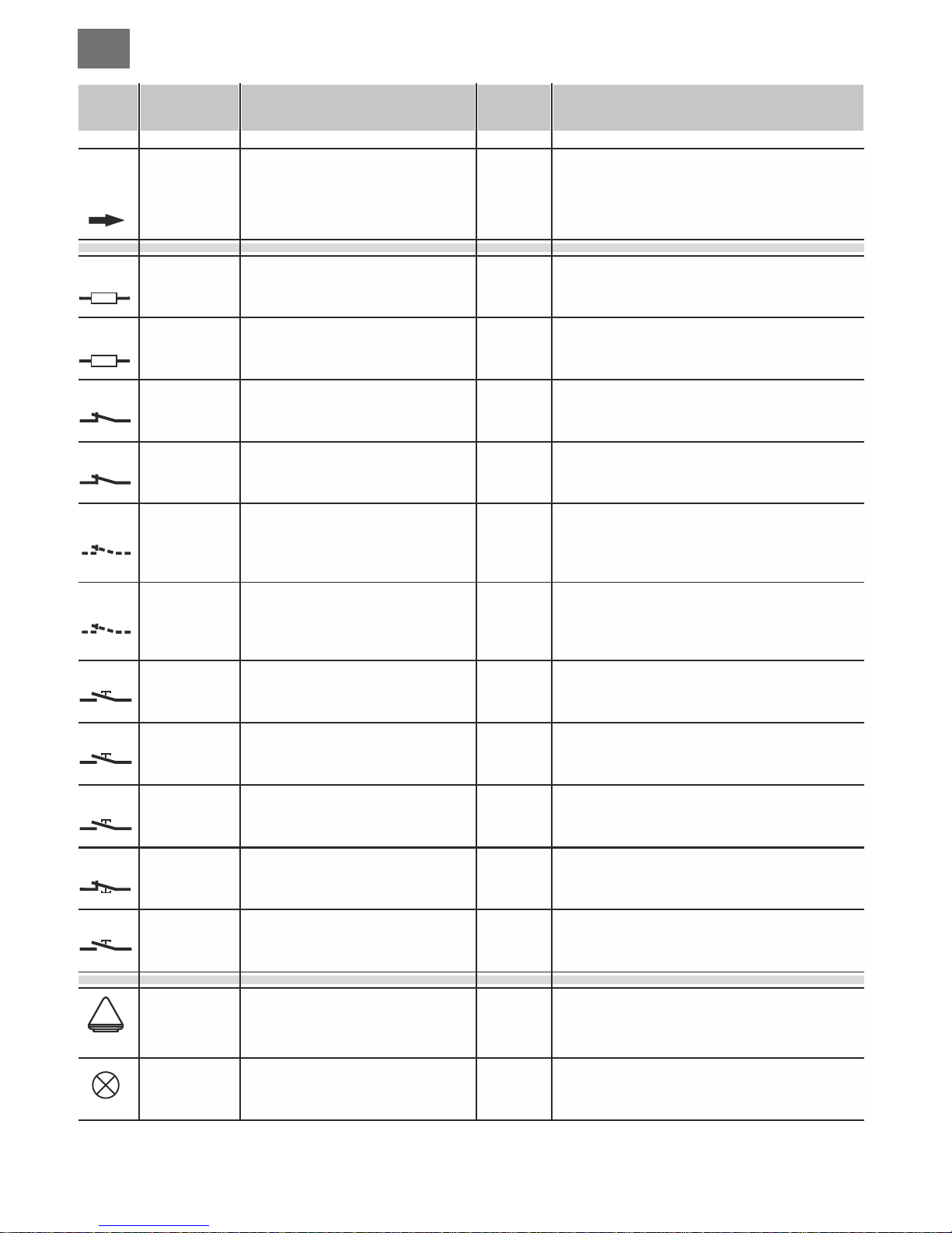
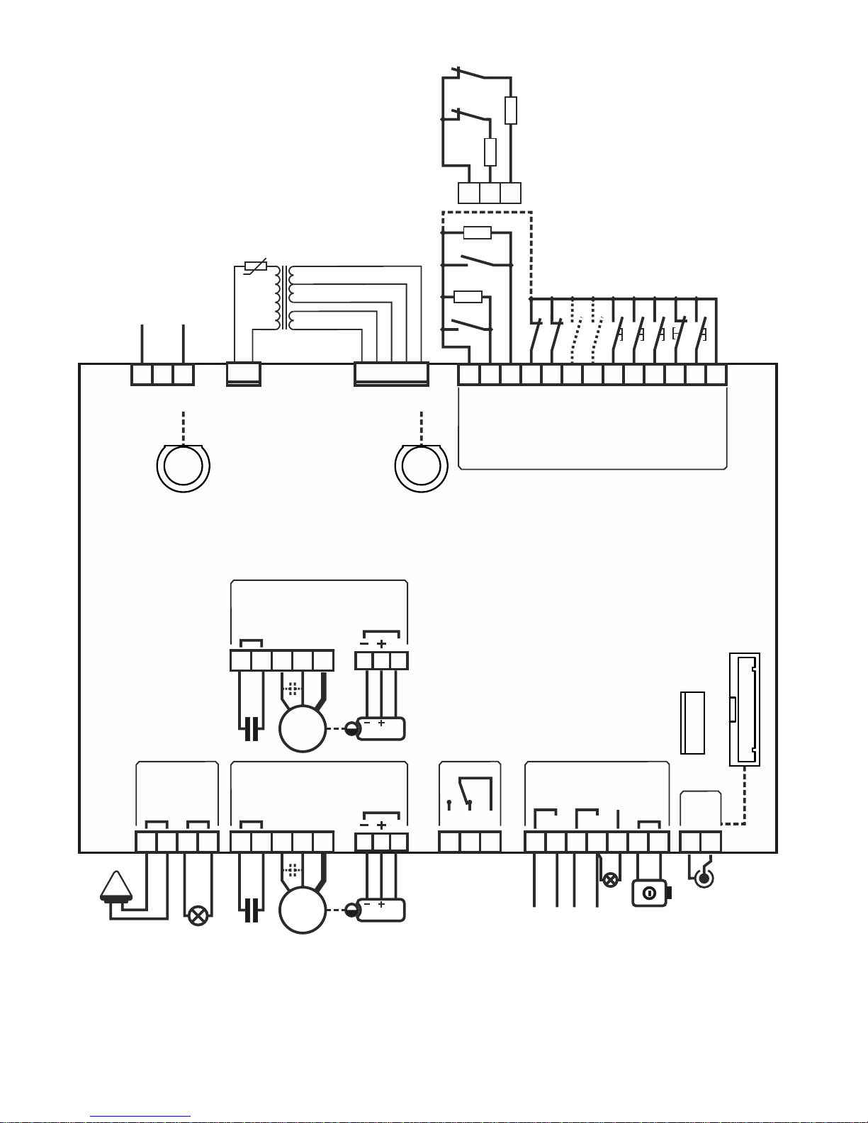
COURTESY LIGHT output
WARNING LAMP output
Safety edge input
Cuts in during CLOSING
Safety edge input
Cuts in during OPENING
Photoelectric cell input
Photoelectric cell input
Input for selectable functions
Input for selectable functions
STOP button input
PEDESTRIAN command input
STEP BY STEP command
Command input
CLOSE
Command input
OPEN
power supply input
18
19
16
17
3,15 (com)
4
3,15 (com)
5
3,15 (com)
6
3,15 (com)
7
3,15 (com)
8
3,15 (com)
9
3,15 (com)
13
3,15 (com)
12
3,15 (com)
14
3,15 (com)
10
3,15 (com)
11
1 (L)
2 (N)
Function / Device Function / DeviceTerm. n. Term. n.
/
/
/
/
/
/
/
/
/
/
/
/
/
/
/
230V/1A
230V/1A
8K2/NC
8K2/NC
NC
NC
-
-
NC
NA
NA
NA
NA
230/6A
V/I max V/I max
Output active for the entire manoeuvre plus 120”
after complete closing.
Output active while the motor is working
Input for closing direction enabled. Connect 8,2K safety
edges or an N.C. contact with 8,2K resistance in series (fig.
E). If unused (binding post free), set dip 1 to ON (part. 23 fig.
A).
Input for opening direction enabled. Connect 8,2K safety
edges or an N.C. contact with 8,2K resistance in series (fig.
E). If unused (binding post free), set dip 2 to ON (part. 23 fig.
A).
Travel direction inversion during closing.
If unused (binding post free), set dip 3 to ON (part. 23
fig. A).
Temporary movement block during the opening stage.
Travel direction inversion during closing.
If unused (binding post free), set dip 4 to ON (part. 23
fig. A).
See dip-switch setting 3 and 4 (part. 19 fig. A).
If unused, set dips 3 and 4 to OFF and then set dip
5 (part. 23 fig. A) to OFF.
See dip-switch setting 3 and 4 (part. 19 fig. A).
If unused, set dips 3 and 4 to OFF and then set dip
6 (part. 23 fig. A) to ON.
Blocks all functions.
If unused, set dip 7 to ON (part. 23 fig. A)
With a 2 motor installation, only M1 opens.
With a 1 motor installation it opens partially for a set
amount of time (see “programming pedestrian
opening”).
See settings for dip 1 and 2 (part. 19 fig. A)
CLOSING only command, during opening it inverts
and closes.
OPENING only command, during closing it inverts
and opens.
Connect to the 230V power supply.
Notes Notes
24V
24V FT
M1
M2
BSC
BSA
FT1
FT2
J1
J2
STP
PED
P/P
PC
PA
US1
230V
ENC
1
ENC
2
12V
24V
230V
230V
8K2*
8K2*
GB
13
Page 14
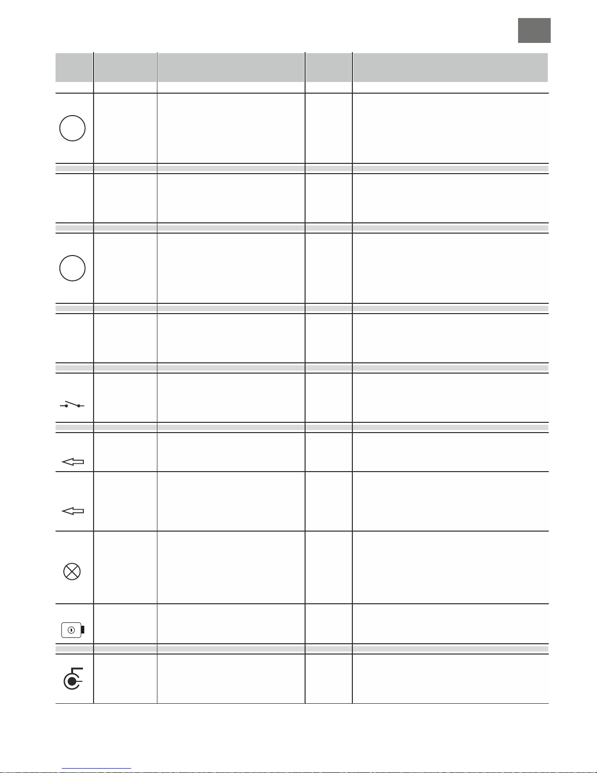
Receiver aerial input
Output for auxiliary device power
supply
Output for Transmitter / Photocell
power supply
Indicator light output
Electric lock output
Contact for selectable functions
Encoder sensor input motor M1
Encoder sensor input motor M2
Output motor M1
Output motor M2
38 Calza
39 Cent.
31
32 (0)
33
34 (0)
35
34 (0)
36
37 (0)
28 (no)
29 (nc)
30 (c)
25 (-)
26 (+)
27 (D)
45 (-)
46 (+)
47 (D)
20 (CON.)
21 (CON.)
22 (AP)
23 (CH)
24 (Com)
40 (CON.)
41 (CON.)
42 (AP)
43 (CH)
44 (Com)
/
/
/
/
/
/
/
/
/
/
/
/
/
/
24ac/0,5A
24ac/0,5A
24ac/0,2A
12dc/1,5A
/4A
5-12V
5-12V
230/4A
230/4A
Connection is only necessary if OC2 is inserted
e.g. photocells, external receivers or other 24Vac
devices
Output only active during the manoeuvre and the
reclosing pause period, connect the photoelectric
cell projectors so that the minimum amount of
power is used. If the jumper (part. 9 di fig. A) is set
to ON this output will be continuously active.
Status indication:
automation CLOSED – led off
during OPENING – flashes slowly
during CLOSING – flashes quickly
STOP (block) – remains lit
during the RECLOSING PAUSE – double flashing
with pause
Activates, for a couple of seconds at the beginning
of each opening cycle
See settings for dip 7 (part. 19 fig. A)
For the motor-ECU connection use a separate cable
(e.g. 3x0,35) with a max. length of 10m
For the motor-ECU connection use a separate cable
(e.g. 3x0,35) with a max. length of 10m
Motor M1 moves first in the opening direction and is
delayed during closing.
An eventual electric lock should be fitted to this gate
leaf.
M2 is the second motor to move and the first one to
close.
24V
24V FT
M1
M2
US1
ENC
1
ENC
2
12V
24V
GB
14
Page 15
1
1
2
2
3
4
5
6
7
IGB
ON
1 2
ON
1 2
ON
1 2
ON
1 2
DIP-SWITCH SETTING
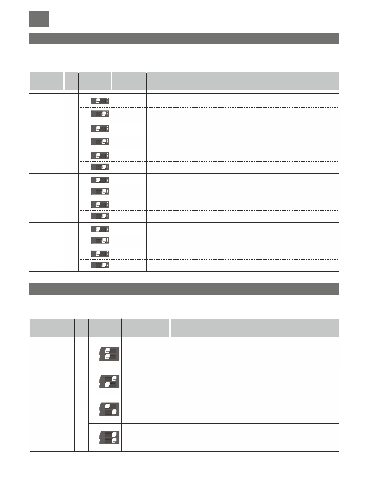
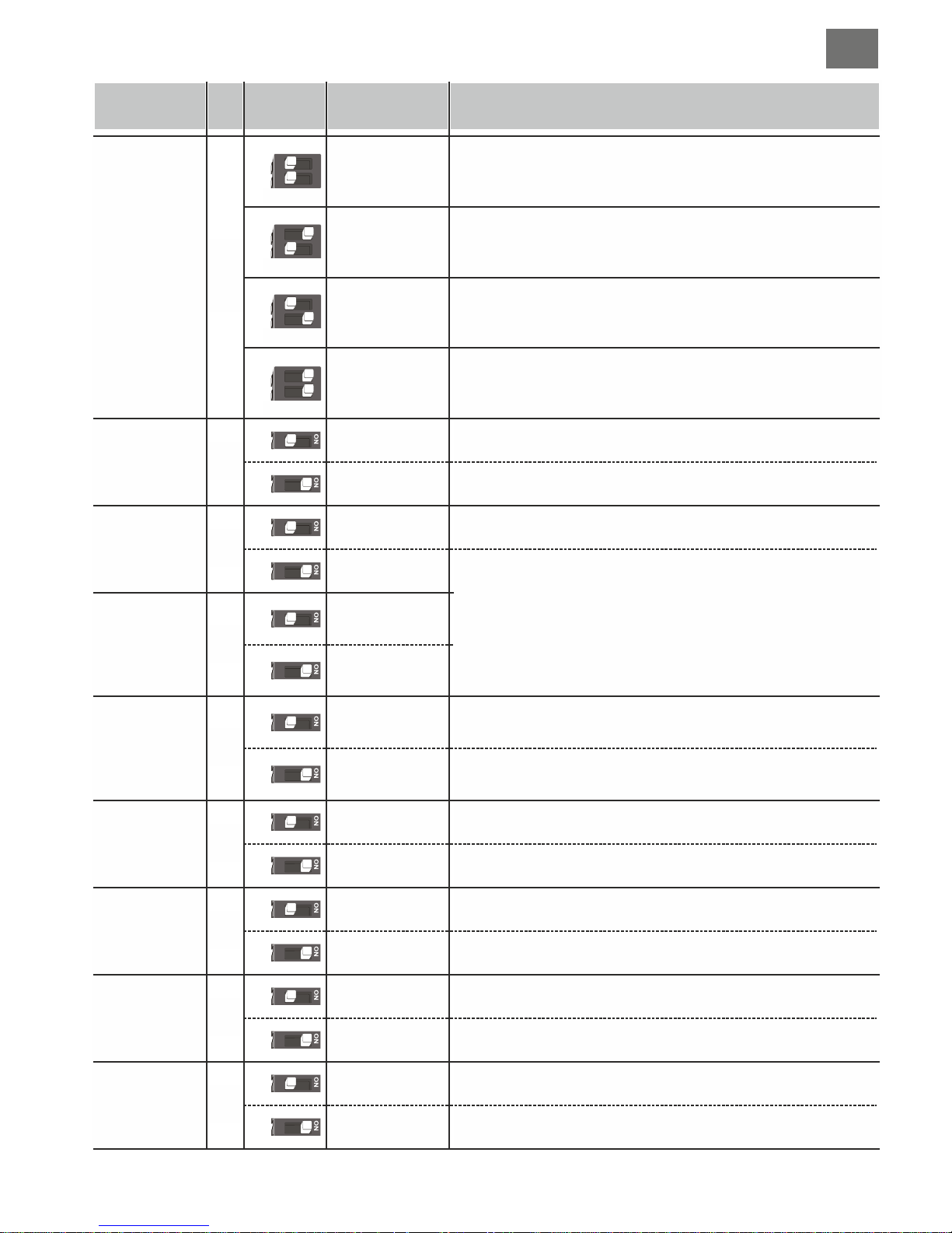
Select the options required and perform a reset (part. 7, fig. L) to render the changes operational.
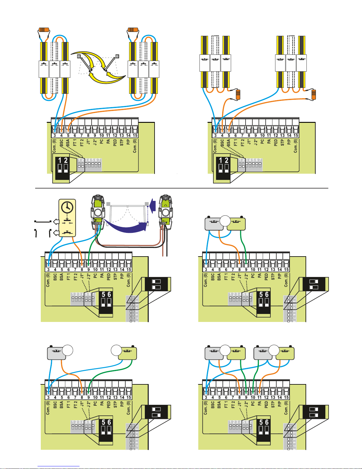
Use these dip-switches (part. 7 fig. L) to excluded inputs of unused safety devices.
A dip-switch set to ON (Excluded) is the same as bridging the Common (binding post 6) and any one of these 7 inputs.
SAFETY DEVICE EXCLUSION DIP-SWITCHES
EXCLUDED
OPEN - STOP CLOSE
JOLLY
INPUT MODE
PREFLASH
RE-CLOSURE
TIMER
US1 OUTPUT
GATE
RELEASE
JOLT
SLOWDOWN
POWER
CLOSING
JOLT
1 - 2 MOTORS
RECLOSING
AFTER THE
PHOTOELECTRIC
CELLS
STEP-BY-STEP
INPUT
AND
RADIO
CHANNEL
MODE (CH1)
OPEN - CLOSE
ALWAYS OPENS
“CONDOMINIUM”
OPENS-CLOSES
with no reversal
during opening
EXCLUDED
EXCLUDED
EXCLUDED
EXCLUDED
EXCLUDED
EXCLUDED
With a closing safety edge installed
Excludes the closing safety edge input.
Attention! Binding post 4 must remain disconnected.
During opening, upon pressing the P/P button the gate stops, pressing it
again the gate closes.
During closing, upon pressing the P/P button the gate stops, pressing it
again the gate opens.
During opening, upon pressing the P/P button the gate stops for a few
seconds and then closes.
During closing, upon pressing the P/P button the gate stops for a few
seconds and then opens.
During opening, pressing the P/Pbutton has no effect. During the pause,
pressing the P/Pbutton has no effect.
During closing, upon pressing the P/P button the gate stops for a few
seconds and then opens.
During opening, pressing the P/Pbutton has no effect. During the pause,
upon pressing the P/Pbutton the gate closes.
During closing, upon pressing the P/P button the gate stops for a few
seconds and then opens.
Excludes the opening safety edge input.
Attention! Binding post 5 must remain disconnected.
Excludes the input for photocell 1. The same as bridging binding post 6 with the
common
Excludes the input for photocell 2. The same as bridging binding post 7 with the
common
Excludes the input J1. The same as bridging binding post 8 with the common
Excludes the input J2. The same as bridging binding post 9 with the common
Excludes the STOP input. The same as bridging binding post 13 with the common
With an opening safety edge installed
With installed photoelectric cells
With installed photoelectric cells
With a device installed
With a device installed
With a STOP button installed
BSC
OFF
OFF
OFF
OFF
OFF
OFF
OFF
OFF
ON
OFF
ON
ON
ON
ON
ON
ON
ON
ON
OFF
OFF
ON
ON
BSA
FT1
FT2
J1
J2
STP
Descrption
Descrption
OFF-ON
Off - On
n.
n.
Modo
Mode
Function
Function
Function
15
Page 16
3
4
5
6
7
8
9
10
11
12
ON
3 4
ON
3 4
ON
3 4
ON
3 4
J1 = TIMER
J2 = FT3
JOLLY
INPUT MODE
PREFLASH
RE-CLOSURE
TIMER
US1 OUTPUT
GATE
RELEASE
JOLT
SLOWDOWN
POWER
CLOSING
JOLT
1 - 2 MOTORS
RECLOSING
AFTER THE
PHOTOELECTRIC
CELLS
J1 = FCA M1
J2 = FCC M1
J1 = FCA M1
J2 = FCA M2
J1 = FCA M1
J2 = FCC M1
PA = FCA M2
PC = FCC M2
EXCLUDED
EXCLUDED
Dray contact
EXCLUDED
EXCLUDED
EXCLUDED
1 MOTOR
EXCLUDED
INSERTED
INSERTED
Channel 2 (OC2)
INSERTED
INSERTED
INSERTED
2 MOTORS
INSERTED
J1=TIMER input; closes the gate when the contact is opened and
opens it when the contact is closed.
J2=third photocell input (FT3); intervenes only during opening and
forces closing. Use N.C. contacts.
Stops only motor M1 using electric travel limits.
Use N.C. contacts
Motors are stopped during OPENING using electric travel limits.
Use N.C. contacts
For installations with 4 travel limits. Connect the travel limits of motor M1
to the inputs FCC and FCA. Connect the travel limits of motor M2 to the
inputs J1 and J2.
Use N.C. contacts
The flashing light operates together with the motor.
After one complete opening, the control unit only closes again with a
manual control.
Function excluded.
There is no slowdown in the last part of travel.
Power closing is not carried out.
Only the M1 output is enabled. The pedestrian command partially opens
and closes motor M1
Function excluded.
The flashing light operates 5 seconds before any operation.
After one complete opening, the control unit closes automatically after the
programmed pause time.
Second radio channel output. If you don't use this function the second
radio channel will activate pedestrian opening.
The gate release jolt is needed to release the electric lock.
The gate with M1 installed will carry out a brief closing movement before
starting the opening cycle.
With the slowdown function connected, the motor halves its speedtowards
The ECU will end the closing manoeuvre with a brief increase to full power
on motor M1.
Enables both motor outputs (M1 and M2). The pedestrian command
completely opens and closes the gate with motor M1.
The activation of photoelectric cell reduces the pause time for whatever
is value previously was to 2
OFF
OFF
OFF
OFF
OFF
OFF
OFF
OFF
OFF
ON
OFF
ON
ON
ON
ON
ON
ON
ON
ON
ON
OFF
OFF
ON
ON
Descrption
Off - On
n.
Mode
Function
GB
This contact gives information regarding the status of the gate.
The relay activates as the gate begins to open and deactivates only
after complete closing has been achieved.
16
Page 17
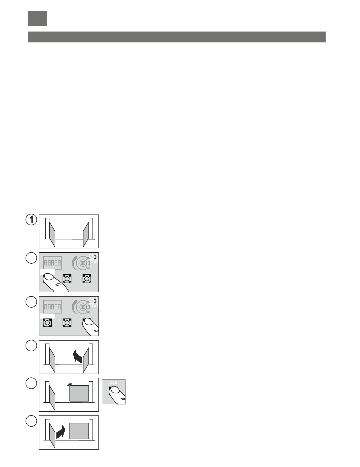
PROGRAMMING THE TRAVEL DISTANCE AND PAUSE TIMES
Programming detects and memorises all the work times necessary for the motor to complete each individual opening and
closing manoeuvre, including the automatic reclosing times.
During the learning stage you'll either press the P/P several times (part. 17, fig. A) or you can use a P/P command at (binding
post 14, fig. C) or a radio control with the channel already memorised (P1).
The sequence of operations changes according to the type of installation and whether or not electrical travel limits or encoder
control has been fitted which the ECU will recognise automatically.
Important considerations before starting programming:
A. Make sure the gate is free from obstacles and that you are standing outside the range of action of any photoelectric cells and
sensors that have been connected to the ECU.
B. Make sure the mechanical opening and closing travel limits have been installed on both the automatic gates.
These must be sufficiently solid in order to stop the movement of the gates.
C. Set the trimmer (part 21, fig. A) at a halfway setting for the first programming attempt and if the motor doesn't manage to
complete the manoeuvre the torque can be increased by rotating the trimmer clockwise.
Choose one of the following programming types:
PROGRAMMING TWO SWING-TO GATES, WITHOUT ENCODER CONTROL AND WITHOUT ELECTRICAL TRAVEL
LIMITS
In this case the installer will have to manually (using the P/P command) input all the travel limits and gate delay information. It is
also possible to input the deceleration times at this point (for the final part of the gates movement) or you may try the default
settings by moving dip 9 to ON after programming.
DIP 9 set to OFF during programming: Deceleration times will not be modified.
DIP 9 set to ON only after programming: Default deceleration times will be set.
DIP 9 set to ON during programming will oblige you to input ALL the deceleration start values after points: 4a, 4c, 6b
and 6d.
Before starting programming check the correct setting and connection of the inputs using the status leds (part. 22, fig. A):
Leds BSC, BSA, FT1, FT2, J2 and STP must be ON.
Leds J1, PC, PA, PED and P/P must be OFF.
Switch off the power to the ECU.
Release the motors and move the gates to the position “almost open”.
Re-engage the motors and switch on the power to the installation.
Hold down the PROG button (part. 15, fig. A) for about 3 seconds until led LD1 lights up
(part. 18, fig. A)
The ECU is now in the programming stage.
Press the P/P button (part. 17, fig. A) the gate with motor M2 should begin to close, if it moves
in the opening direction instead, stop programming by switching off the power, invert the wires
of motor M2 and repeat the procedure from point (1).
2
3b
3a
3d
6d
3c
3e
STOP
STOP
M1
M1
M1
M2
M2
M2
P3
P3
P/P
P/P
LD1
LD1
PROG.
PROG.
6e
5
6a
6b
4c
4d
4a
4b
6c
When the gate with motor M2 has completely closed, press P/P, the motor will stop
and the other motor (M1) will begin to close.
Should the motor move in the opening direction instead, switch off the power,
invert the wires of motor M1 and repeat the procedure from point (1).
If the motors stop before reaching the travel limits increase the torque level
using the trimmer.
17
Page 18
6d
3e
M1
M1
M2
M2
6e
5
M1
M1
M1
M1
M1
M2
M2
M2
M2
M2
6a
6b
FINE PROG.
4c
4d
4a
4b
6c
M1
M1
M1
M1
M2
M2
M2
M2
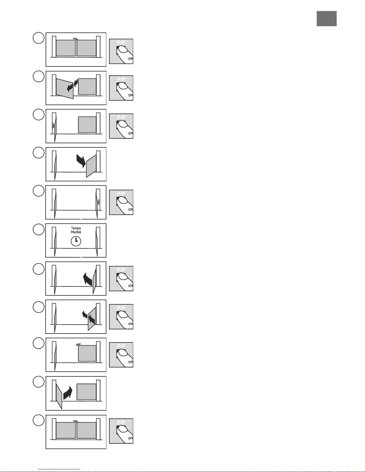
Once M1 has reached the completely closed position, press P/P, the motor will
stop and begin to open automatically.
Press P/P again when M1 has reached the desired gate delay angle, the motor will
stop for a second and then begin to open again.
At this point you must manually insert the DECELERATION start point using
P/P if DIP 9 is set to ON. The motor will stop for a second and then begin to
move again.
When the gate with M1 has opened completely (reaching the mechanical stop)
press P/P to stop the motor, the other motor (M2) will then start to open
automatically.
At this point you must manually insert the DECELERATION start point using
P/P if DIP 9 is set to ON. The motor will stop for a second and then begin to
move again.
When the gate with M2 has opened completely (reaching the mechanical stop)
press P/P to stop the motor, pause time memorisation will start (if automatic
reclosing is not being used you may move directly to point (6a).
Once the desired pause time has elapsed, press button P/P and motor M2 will
begin to close.
Press P/P again when M2 has reached the desired gate delay angle, the motor will
stop for a second and then begin to close again.
At this point you must manually insert the DECELERATION start point using
P/P if DIP 9 is set to ON. The motor will stop for a second and then begin to
move again.
When the gate with M2 has closed completely (reaching the mechanical stop)
press P/P to stop the motor, the other motor (M1) will begin to close.
At this point you must manually insert the DECELERATION start point using
P/P if DIP 9 is set to ON. The motor will stop for a second and then begin to
move again.
When the gate with M1 has completely closed, press P/P, the motor will stop, led
LD1 will switch off and the ECU will quit the programming mode.
Checks: force, times and stopping points. We advise you to consider inserting
deceleration points (DIP 9 set to ON) to reduce impact against the travel limits so
reducing wear and tear on the mechanical parts.
Repeat programming if you have modified the mechanical travel limits.
GBIGB
18
Page 19
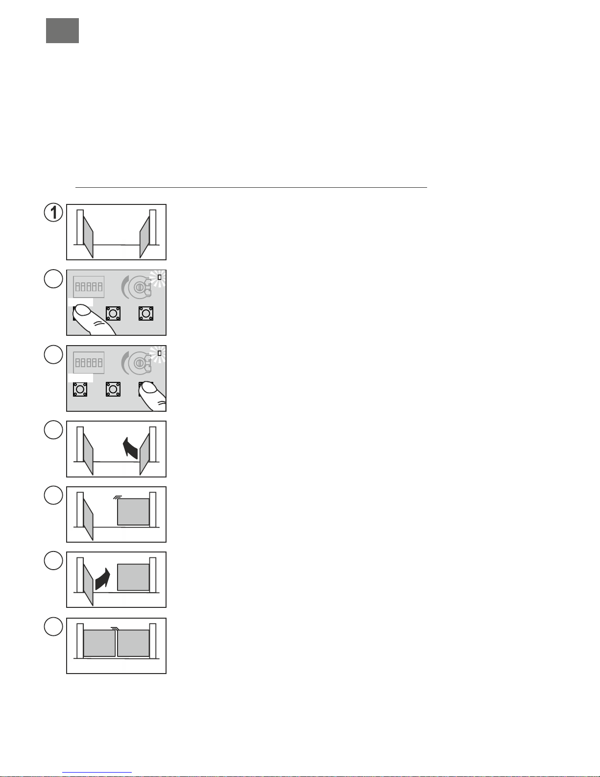
PROGRAMMING TWO SWING-TO GATES, WITH ENCODER CONTROL AND WITHOUT ELECTRICAL
TRAVEL LIMITS
In this case the ECU will automatically detect all the travel limit information. Programming is more precise and
quicker thanks to the encoder sensors. The gate delay between the two gate leaves and deceleration points and
times will be inserted automatically. To modify them you need only insert the new values during EVOLVED
programming after point 3e.
Before starting programming check the correct setting and connection of the inputs using the status leds (part. 22,
fig. A):
Leds BSC, BSA, FT1, FT2, J2 and STP must be ON.
Leds J1, PC, PA, PED and P/P must be OFF.
Even with Encoder control the mechanical opening and closing travel limits must be installed on both the automatic
gates. These must be sufficiently solid in order to stop the movement of the gates.
From this point on we can proceed in two ways:
STANDARD programming using the default GATE DELAY and DECELERATION values, move on to point 4a.
Evolved programming, move on to point 7a to insert personalised GATE DELAY and deceleration values.
EVOLVED programming
DIP 9 set to OFF during programming: Deceleration times will NOT be modified.
DIP 9 set to ON only after programming: Default deceleration times will be set.
DIP 9 set to ON during programming: the ECU is ready to receive personalised deceleration values.
You do not have to set all the values.
Switch off the power to the ECU.
Release the motors and move the gates to the position “almost open”.
Re-engage the motors and switch on the power to the installation.
Hold down the PROG button (part. 15, fig. A) for about 3 seconds until led LD1 lights up
(part. 18, fig. A)
The ECU is now in the programming stage.
Press button P/P (part. 17, fig. A) the gate with motor M2 should begin to close, if it moves in
the opening direction instead, stop programming by switching off the power, invert the wires of
motor M2 and repeat the procedure from point (1).
A led close to the ENC M2 terminal block will light up (flashing) (part. 7, fig. A) during
movement indicating the correct operation of encoder M2.
If the motors stop before reaching the travel limits increase the torque level using the
trimmer.
2
3b
3a
3d
6b
3c
3e
STOP
STOP
M1
M1
M1
M1
M2
M2
M2
M2
P3
P3
P/P
P/P
LD1
LD1
PROG.
PROG.
6c
5
6a
4a
4b
When the gate with motor M2 has completely closed, the motor will stop and the other motor
(M1) will begin to close.
Should the motor move in the opening direction instead, switch off the power, invert the wires
of motor M1 and repeat the procedure from point (1).
If the motors stop before reaching the travel limits increase the torque level using the trimmer.
When the gate with motor M1 has completely closed, the motor will stop and begin to open
automatically.
7c
7a
7b
8
19
Page 20
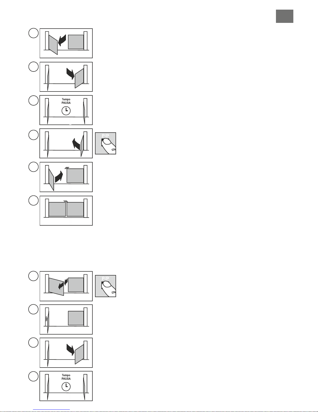
EVOLVED programming
DIP 9 set to OFF during programming: Deceleration times will NOT be modified.
DIP 9 set to ON only after programming: Default deceleration times will be set.
DIP 9 set to ON during programming: the ECU is ready to receive personalised deceleration values.
You do not have to set all the values.
6b
M1
M2
6c
5
M1
M1
M1
M2
M2
M2
6a
FINE PROG.
4a
4b
M1
M1
M2
M2
STANDARD programming
After having found the M1 closing travel limit it will open automatically.
When the gate with M1 finds the opening travel limit, the other motor M2 will begin
to move.
When the gate with M2 has opened completely (reaching the mechanical stop),
pause time memorisation will start (if automatic reclosing is not being used you
may move directly to point (6a).
Once the desired pause time has elapsed, press button P/P and motor M2 will
begin to close.
When the gate with M2 has found the closing travel limit, the other motor M1 will
begin to close.
When the gate with M1 has closed completely, the motor will stop, led LD1 will
switch off and the ECU will quit programming
Checks: force, times and stopping points. We advise you to consider inserting
deceleration points (DIP 9 set to ON) to reduce impact against the travel limits so
reducing wear and tear on the mechanical parts.
Repeat programming if you have modified the mechanical travel limits.
After point 3e the gate with M1 will start to open.
Press P/P when M1 has reached the desired gate delay angle, the motor will stop
for a second and then continue the opening cycle.
After this point we can manually insert the DECELERATION start points
using P/P (DIP 9 set to ON) the motor will stop for a second then start again.
Otherwise wait until the gate reaches the travel limit.
When the gate with M1 has opened completely, the motor will stop and the other
motor (M2) will start to move automatically.
After this point we can manually insert the DECELERATION start points
using P/P (DIP 9 set to ON) the motor will stop for a second then start again.
Otherwise wait until the gate reaches the travel limit.
When the gate with M2 has opened completely (reached the travel limit), the motor
will stop and the pause time memorisation will start (if automatic reclosing is not
being used you may move directly to point (6a).
7c
7a
7b
M1
M1
M1
M2
M2
M2
8
M1 M2
GBIGB
20
Page 21
9d
M1
M1
M1
M2
M2
M2
9a
9b
FINE PROG.
9c
M1 M2
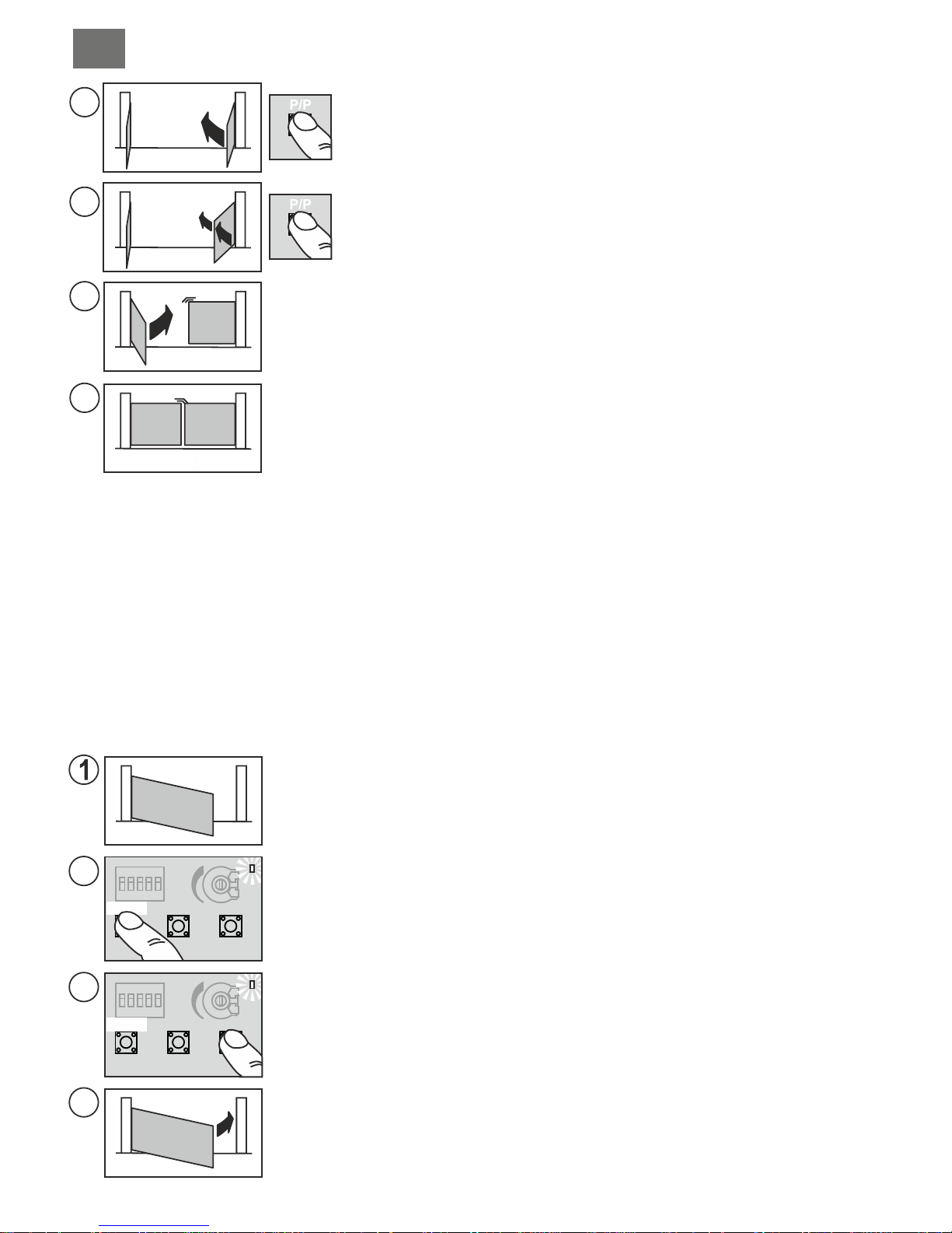
Press P/P again when M2 has reached the desired gate delay angle, the motor will
stop for a second and then begin to close.
After this point we can manually insert the deceleration start points using
P/P (DIP 9 set to ON) the motor will stop for a second then start again.
Otherwise wait until the gate reaches the travel limit.
When the gate with M2 reaches the closing travel limit, the other motor M1 will
move.
After this point we can manually insert the deceleration start points using
P/P (DIP 9 set to ON) the motor will stop for a second then start again.
Otherwise wait until the gate reaches the travel limit.
When the gate with M1 has closed completely, the motor will stop, led LD1 will
switch off and the ECU will quit programming.
Checks: force, times and stopping points. We advise you to consider inserting
deceleration points (DIP 9 set to ON) to reduce impact against the travel limits so
reducing wear and tear on the mechanical parts.
Repeat programming if you have modified the mechanical travel limits.
PROGRAMMING ONE SWING-TO GATE, WITHOUT ENCODER CONTROL AND WITHOUT ELECTRICAL
TRAVEL LIMITS
Motor wired to the output M1 and DIP11 set to OFF
In this case the installer will have to manually (using the P/P command) input all the travel limit information. It is also
possible to input the deceleration times at this point (for the final part of the gate movement) or you may try the
default settings by moving dip 9 to ON after programming.
DIP 9 set to OFF during programming: Deceleration times will not be modified.
DIP 9 set to ON only after programming: Default deceleration times will be set.
DIP 9 set to ON during programming will oblige you to input ALL the deceleration start values after points:
4a, 4c, 6b and 6d.
Before starting programming check the correct setting and connection of the inputs using the status leds (part. 22,
fig. A):
Leds BSC, BSA, FT1, FT2, J2 and STP must be ON.
Leds J1, PC, PA, PED and P/P must be OFF.
Switch off the power to the ECU.
Release the motor and move the gate to the position “almost open”.
Re-engage the motor and switch on the power to the installation.
Hold down the PROG button (part. 15, fig. A) for about 3 seconds until led LD1 lights up
(part. 18, fig. A)
The ECU is now in the programming stage.
Press the P/P button (part. 17, fig. A) the gate should begin to close, if it moves in the opening
direction instead, stop programming by switching off the power, invert the wires of the motor
and repeat the procedure from point (1).
If the motor stops before reaching the travel limits increase the torque level using the
trimmer.
2
3b
3a
3c
STOP
STOP
M1
M1
P3
P3
P/P
P/P
LD1
LD1
PROG.
PROG.
4a
4b
5
6a
6b
PROGRAMMING ONE SWING-TO GATE, WITH ENCODER CONTROL AND WITHOUT ELECTRICAL
TRAVELLIMITS
The procedure is the same as the previous paragraph but you do not need to press P/P at points 3c, 4b and
6b.
In this case the ECU will AUTOMATICALLY detect all the travel limit information. Programming is more precise and
quicker thanks to the encoder sensor. The deceleration points and times will be inserted automatically. To modify
them you need only insert the new values during programming (DIP9 set to ON).
This procedure allows you to modify the pause time set during a previous programming procedure.
This operation must be carried out with the gate closed.
1) Press the PROG button (part. 15, fig. A) and hold it down until the Led LD1 remains lit (part. 18, fig. A)
2) Press the PROG button again, led LD1 will start to flash and the ECU will begin to memorise the pause time.
3) Once the desired pause time has elapsed, press the PROG button. Led LD1 will switch off and the procedure will terminate.
MODIFYING THE PAUSE TIMES
According to the standard EN 12445 every automation installation must pass the impact test measured with the specific
instrument.
Carry out the impact test and adjust the motor force by rotating the trimmer (part. 21, fig. A).
If this is not sufficient to remain within the boundaries of the graph supplied by the standards in force, we advise you to install a
rubber protective edge at the head of the gate so as to soften the impact.
If you have adjusted the sensitivity setting and added a rubber profile to the head of the gate and you are still unable to satisfy
the standards in force, you will need to add other safety devices such as a sensitive safety edge to the moving part of the gate.
SENSITIVITY ADJUSTMENT
21
Page 22
3c
M1
M1
M1
M1
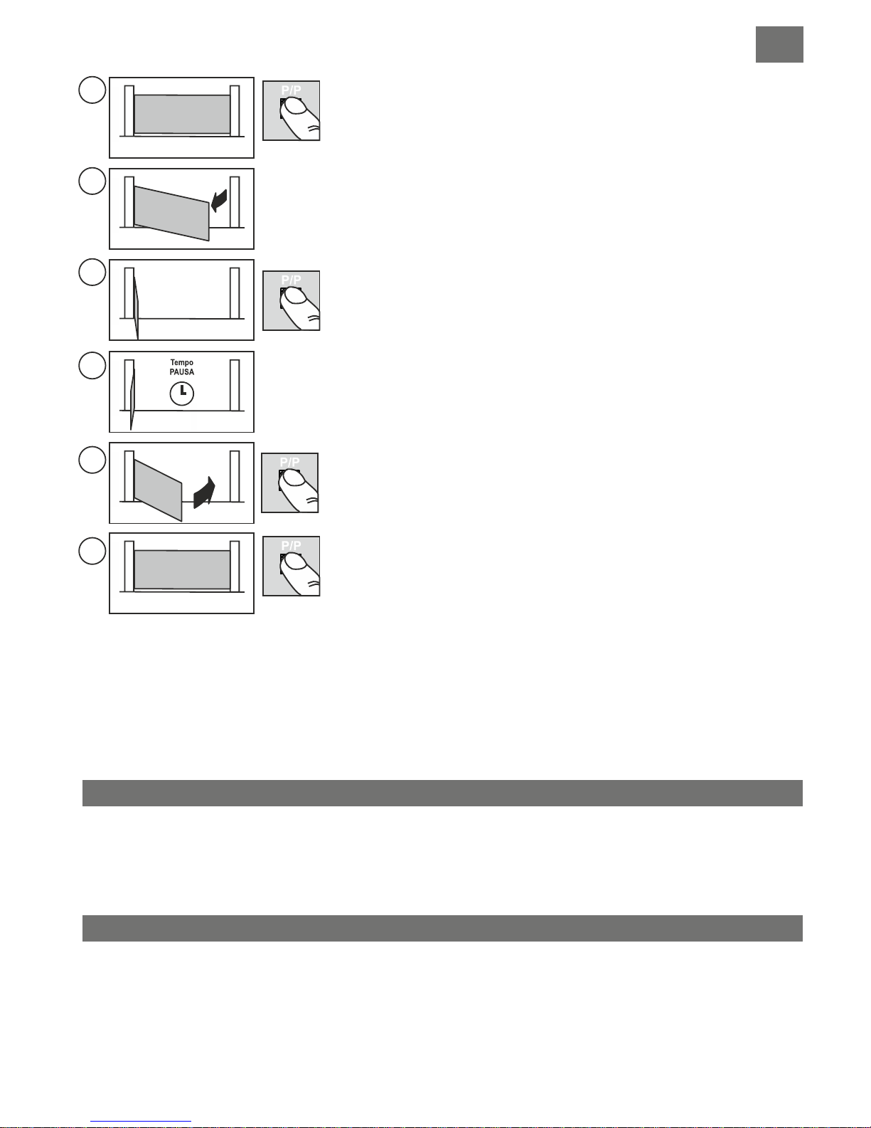
When the gate has completely closed, press P/P, the motor will stop and begin to
open automatically.
At this point you may manually insert the DECELERATION start point using
P/P if DIP 9 is set to ON. The motor will stop for a second and then begin to
move again.
When the gate has opened completely (reaching the mechanical stop) press P/P
to stop the motor, pause time memorisation will start (if automatic reclosing is not
being used you may move directly to point (6a).
Once the desired pause time has elapsed, press button P/P and the motor will
begin to close.
At this point you may manually insert the DECELERATION start point using
P/P if DIP 9 is set to ON. The motor will stop for a second and then begin to
move again.
When the gate has completely closed, press P/P, the motor will stop, led LD1 will
switch off and the ECU will quit the programming mode.
Checks: force, times and stopping points. We advise you to consider inserting
deceleration points (DIP 9 set to ON) to reduce impact against the travel limits so
reducing wear and tear on the mechanical parts.
Repeat programming if you have modified the mechanical travel limits.
4a
4b
5
M1
M1
6a
6b
FINE PROG.
PROGRAMMING ONE SWING-TO GATE, WITH ENCODER CONTROL AND WITHOUT ELECTRICAL
TRAVEL LIMITS
The procedure is the same as the previous paragraph but you do not need to press P/P at points 3c, 4b and
6b.
In this case the ECU will AUTOMATICALLY detect all the travel limit information. Programming is more precise and
quicker thanks to the encoder sensor. The deceleration points and times will be inserted automatically. To modify
them you need only insert the new values during programming (DIP9 set to ON).
This procedure allows you to modify the pause time set during a previous programming procedure.
This operation must be carried out with the gate closed.
1) Press the PROG button (part. 15, fig. A) and hold it down until the Led LD1 remains lit (part. 18, fig. A)
2) Press the PROG button again, led LD1 will start to flash and the ECU will begin to memorise the pause time.
3) Once the desired pause time has elapsed, press the PROG button. Led LD1 will switch off and the procedure will terminate.
MODIFYING THE PAUSE TIMES
According to the standard EN 12445 every automation installation must pass the impact test measured with the specific
instrument.
Carry out the impact test and adjust the motor force by rotating the trimmer (part. 21, fig. A).
If this is not sufficient to remain within the boundaries of the graph supplied by the standards in force, we advise you to install a
rubber protective edge at the head of the gate so as to soften the impact.
If you have adjusted the sensitivity setting and added a rubber profile to the head of the gate and you are still unable to satisfy
the standards in force, you will need to add other safety devices such as a sensitive safety edge to the moving part of the gate.
SENSITIVITY ADJUSTMENT
GBIGB
22
Page 23
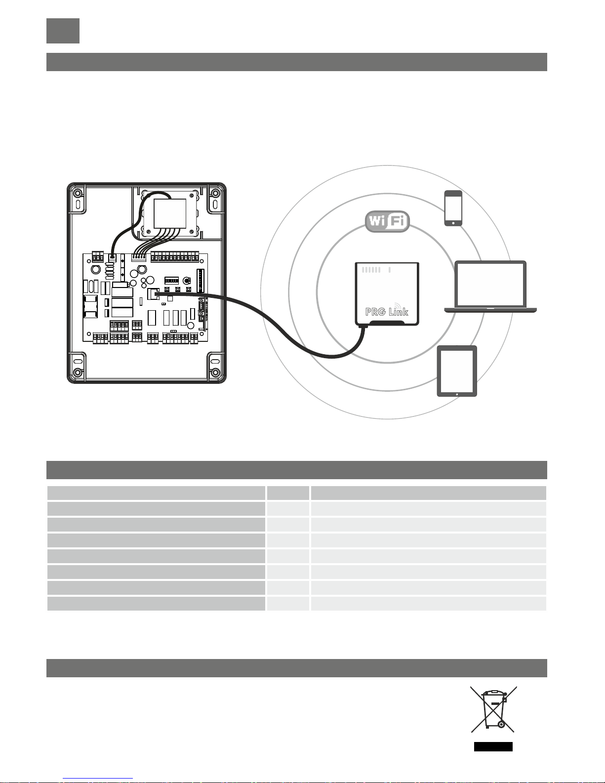
The PRG LINK system is a WI-FI interface dedicated to programming, control and diagnostics of the latest generation
Telcoma ECU's.
Using PRG LINK and its dedicated software application, the operator takes advantage of a powerful Wi-Fi network that allows
him to intervene on the ECU without having to directly access the dip-switches.
A laptop, tablet or smart phone is all that's needed to run quick and precise diagnostic processes.
An advantageous solution for all those who have to manage installations on a daily basis and in the future would like to do so
by means of a long-distance Wi-Fi connection.
MODIFYING AND CONTROLLING SETTINGS USING PRG-Link (optional)
This product ismade up of various components that could contain pollutants.Dispose of properly!
Make enquiries concerning the recycling or disposal of the product, complying with the local laws in
force.
DISPOSAL
TECHNICAL DATA
Mains power supply
Number of motor outputs
Motor power supply
Maximum electrical input
Protection class
Maximum motor power
Operating temperature
230/50Vac/Hz
T600U.M.
2
V 230
A 6
W 2 x 800 (1 x 1200)
°C -20 +55
56IP
IGB D
FUNKTIONEN UND BESCHREIBUNG DER TEILE
Steuer- und Befehlszentrale für 1 oder 2 Motoren (230 V) zur Toröffnung, nachfolgend die wichtigsten Funktionen und
Merkmale:
- Motorausgänge 230V mit DREHMOMENTBESCHRÄNKUNG, VERLANGSAMUNG und SOFT START.
- DOPPELTER EINGANG für die DIREKTSTEUERUNG VON SICHERHEITSSCHALTLEISTEN (8,2K)
- V i e l s e i t i g e St e u e r u n g u nd B e gr e n z un g d e r “To r f l ü g e l b e we g u ng “ d u r c h EN C O D E R - od e r
ZEITSCHALTERKONTROLLIERTE SENSOREN
- Fortschrittliche Programmierung und Diagnostik mit dem neuen PRG-Link (optional)
- Netzfilter und Eingänge mit optischer Isolierung für STÖRUNGSSCHUTZ
- Einfaches AUSSCHLIESSEN NICHTVERWENDETER EINGÄNGE (Sicherheit).
VORPRÜFUNGEN UND WICHTIGE HINWEISE ZUR INSTALLATION
Vor Ausführung der Installation wird empfohlen, folgende Punkte zu überprüfen:
1. die Solidität der bestehenden Strukturen (Pfosten, Scharniere, Torflügel) im Verhältnis zu den durch den Motor erzeugten
Kräften.
2. das Vorhandensein angemessen starker mechanischer Anschläge am Ende der Öffnungs- und Schließphasen der
Torflügel.
3. die Abwesenheit von Reibung oder übermäßigem Spiel in dem unteren Rad/Schienensystem und den oberen
Rollen/Führungen.
4. den Ausschluss des eventuell vorhandenen manuell zu bedienenden Schlosses.
5. den Zustand aller bereits in der Anlage vorhandenen elektrischen Kabel.
Wichtige Hinweise:
1. Die Installation der Automatisierungsanlage muss fachgerecht von qualifiziertem Personal durchgeführt werden, das die
gesetzlichen Anforderungen erfüllt sowie der Maschinenrichtlinie 98/37/EG und den Normen EN13241-1, EN 12453 und EN
12445 entsprechen.
2. Eine Risikoanalyse der Automatisierung durchführen und dementsprechend die notwendigen Sicherheits- und
Signalisierungsmaßnahmen zur Anwendung bringen.
3. Die Steuergeräte (z.B. Schlüsselschalter) so installieren, dass der Benutzer sich nicht in einem gefährlichen Bereich
befindet.
4. Das Etikett oder das CE-Schild an der Automation anbringen, auf dem Informationen über die Gefahren und die
Identifikationsdaten wiedergegeben sind.
5. Dem Endbenutzer die Betriebsanleitung, die Sicherheitshinweise und die EG-Konformitätserklärung aushändigen.
6. Sicherstellen, dass der Benutzer den korrekten automatischen, manuellen und Notfallbetrieb verstanden hat.
7. Nach Abschluss der Installation mehrmals die Sicherheitseinrichtungen, die Signalgebung und die Freigabe der
Automatisierung überprüfen.
8. Dem Benutzer schriftlich (z.B. in der Betriebsanleitung) folgende Informationen und Empfehlungen zu geben:
a. über eventuell vorhandene ungeschützte Restrisiken und vorhersehbare mögliche Fehlanwendungen;
b. vor dem Entriegeln des Torflügels, bei der Durchführung kleinerer Wartungsarbeiten oder wenn im Bereich der
Automatisierung Reinigungsarbeiten durchgeführt werden, die Stromversorgung zu unterbrechen;
c. häufig zu überprüfen, dass keine sichtbaren Schäden an der Automatisierung vorhanden sind und gegebenenfalls sofort
den Installateur zu benachrichtigen;
d. darauf zu achten, dass in unmittelbarer Nähe der Automatisierung das Spielen von Kindern nicht erlaubt ist;
e. Fernbedienungen und andere Steuergeräte außerhalb der Reichweite von Kindern zu halten;
9. einen Wartungsplan für die Anlage festzulegen (mindestens alle 6 Monate) und in einem besonderen Register die
Berichterstattung über die eindurchgeführten Arbeiten festzuhalten.
Beschreibung der Bauteile (Abb.)
1. 230V-Stromeingangsklemme
2. 5A-Sicherung für den Schutz der 230V-Leitung
3. Klemmleisten 230V-Ausgänge für Signallicht und
“Bedienungsbeleuchtung“
4. 230V-Stromausgangsklemme für Motor M1
5. 230V-Ausgangsklemme für Motor M2
6. Klemmleiste Eingang ENCODER M1
7. Klemmleiste Eingang ENCODER M2
8. Klemmleiste Ausgang Kontakt US1
9. Jumper für Dauerbeleuchtung der Lichtschranken
10. Klemmleiste Hilfsausgänge 12/24V
11. Klemmleiste Eingang Empfängerantenne OC2
12. Anschlussstecker für Empfänger OC2
13. Tastaturanschlussstecker TAST 3F
14. Anschlussklemmen für laufende Reset-Verfahren
15. PROGRAMMIER- und STOPPTASTE
16. Taste P3
17. SCHRITT-FÜR-SCHRITT-Taste (P/P)
23
Page 24
PRG
230 V
22-03-2016
DCE105
CARDIN ELETTRONICA spa
Via del lavoro, 73 – Z.I. Cimavilla 31013 Codognè (TV) Italy
Tel.: (+39) 04 38 40 40 11
Fax: (+39) 04 38 40 18 31
e-mail (Italy): [email protected]
e-mail (Europe): [email protected]
http: www.cardin.it
Il costruttore: CARDIN ELETTRONICA S.p.A.
DICHIARA CHE L'APPARECCHIATURA DESTINATA AD ESSERE INSERITA IN
MACCHINE E NON FUNZIONANTE IN MODO INDIPENDENTE:
MODELLO
DATA
CODICE
SERIE
Dichiarazione di Conformità CE
( Dichiarazione del costruttore )
DICHIARA CHE L'APPARECCHIATURA È IDEATA PER ESSERE INCORPORATA IN UNA MACCHINA O PER ESSERE ASSEMBLATA CON ALTRI
MACCHINARI PER COSTITUIRE UNA MACCHINA CONSIDERATA DALLA DIRETTIVA 2006/42/CE E SUCCESSIVI EMENDAMENTI.
INOLTRE DICHIARA CHE NON È CONSENTITO METTERE IN SERVIZIO L' APPARECCHIATURA FINO A CHE LA MACCHINA NELLA QUALE
SARÀ INCORPORATA E DELLA QUALE DIVENTERÀ COMPONENTE NON SIA STATA IDENTIFICATA E DICHIARATA LA CONFORMITÀ ALLE DISPOSIZIONI DELLA DIRETTIVA 2006/42/CEE E SUCCESSIVI EMENDAMENTI.
Cardin Elettronica si impegna a trasmettere, in risposta a una richiesta adeguatamente motivata delle autorità nazionali, informazioni pertinenti sulla
quasi-macchina in oggetto.
Codognè il 20/10/2015
Persona autorizzata a costituire la documentazione tecnica
Ing. A. Fiorotto (Responsabile tecnico
R&D Laboratory)
Rappresentante legale dell'azienda
Dott. Cristiano Cardin (Amministratore delegato
)
- La dichiarazione di conformità CE per i prodotti Cardin è disponibile in lingua originale nel sito www.cardin.it nella sezione "norme
e certificazione" attraverso il link:
- Les déclarations de conformité CE des produits Cardin sont disponibles dans la langue originale sur le site www.cardin.it dans la
section "normes et certificats" par le lien :
- Las declaraciones de conformidad CE de los productos Cardin se encuentran disponibles en el idioma original en el sitio
www.cardin.it en la sección "normas y certificaciones” en el enlace:
- The CE conformity declaration for Cardin products is available in original language from the site www.cardin.it under the section
"Standards and Certification" via the link:
- Die CE-Konformitätserklärungen für die Cardin-Produkte stehen in der Originalsprache auf der Homepage www.cardin.it im
Bereich "Normen und Zertifizierung" zur Verfügung unter dem Link:
http://www.cardin.it/Attachment/dce105.pdf
Nome dell'apparato Centralina elettronica per 1 o 2 motori 230 Vac
Tipo di apparato Centralina elettronica
Modello PRG230M2 - T600
Marchio Cardin Elettronica
Anno di prima fabbricazione 2016
e sono state applicate le seguenti norme e/o specifche tecniche:
- EN 55014-1 : 2006+A1+A2
- EN 55014-2 : 1997+A1:2001+A2:2008
- EN 61000-3-2 : 2006+A1+A2
- EN 61000-3-3 : 2013
- EN 60335-1 : 2011
- EN 62233 : 2008
è conforme alle disposizioni delle seguenti direttive comunitarie:
- Direttiva 2014/30/EU (Compatibilità Elettromagnetica)
- Direttiva 2014/35/EU (Bassa Tensione)
 Loading...