

Page 1
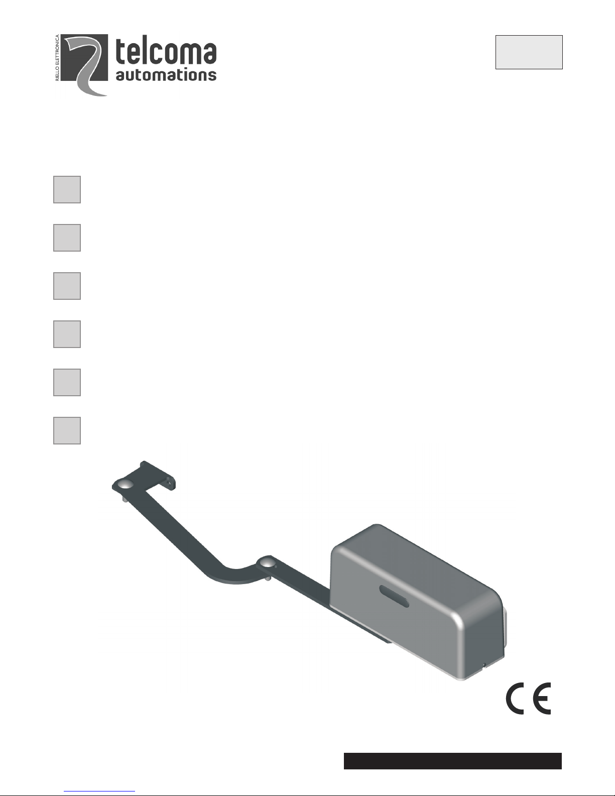
ARM - ARM24
V. 04.2008
MOTORIDUTTORE ELETROMECCANICO IRREVERSIBILE PER ANTE BATTENTI
MANUALE ISTRUZIONI E CATALOGO RICAMBI
IL PRESENTE LIBRETTO È DESTINATO AL PERSONALE TECNICO QUALIFICATO ALLE INSTALLAZIONI
OPÉRATEUR ÉLECTROMÉCANIQUE IRRÉVERSIBLE POUR PORTES BATTANTES
NOTICE D’INSTRUCTION ET CATALOGUE PIECES DE RECHANGE
CETTE NOTICE S'ADRESSE À DES TECHNICIENS SPÈCIALISÈS DANS L'INSTALLATION
MOTORREDUCTOR ELECTROMECÁNICO IRREVERSIBLE PARA HOJAS DE BATIENTE
MANUAL INSTRUCCIONESY CATALOGO REPUESTOS
EL PRESENTE MANUAL ESTÁ DESTINADO AL PERSONAL TECNICO ESPECIALIZADO EN INSTALACIONES
IRREVERSIBLE ELECTROMECHANICAL GEARMOTOR FOR SWING GATES
INSTRUCTION HANDBOOK AND SPARE PARTS CATALOGUE
THIS HANDBOOK IS INTENDED FOR QUALIFIED TECHNICAL INSTALLERS
SELBSTHEMMENDER ELEKTROMECHANISCHER ANTRIEB FÜR DREHTORE
BEDIENUNGSANWEISUNGEN UND ERSATZTEILLISTE
DAS VORLIEGENDE HANDBUCH IST FÜR DAS MIT DER INSTALLATION BETRAUTE TECHNISCH
QUALIFIZIERTE FACHPERSONAL BESTIMMT
ONOMKEERBARE ELEKTROMECHANISCHE REDUCTIEMOTOR VOOR DRAAIENDE VLEUGELS
GEBRUIKERSHANDLEIDING EN RESERVEONDERDELEN-CATALOGUS
DEZE HANDLEIDING IS BESTEMD VOOR VAKBEKWAME INSTALLATEURS
F
I
E
GB
D
NL
Telcoma srl - Via L. Manzoni, 11 - Z.I. Campidui - 31015 Conegliano - (TV) Italy
Tel. +39 0438-451099 - Fax +39 0438-451102 - Part. IVA 00809520265
http://www.telcoma.it E-mail: info@telcoma .it
ISTARM
Page 2
3
IFE
ARM: Motoriduttore elettromeccanico irreversibile con
sblocco manuale. Alimentazione monofase 230 Vac,
fine-corsaelettrici incorporatie uscitaper Encoder.
ARM24: Motoriduttore elettromeccanico irreversibile
con sbloccomanuale.Alimentazione 24Vdc fine-corsa
elettriciincorporati euscita perEncoder.
ARM: opérateur électromécanique irréversible à
débrayage manuel. Alimentation monophasée 230
Vca, fins de course électriques incorporés et sortie
pour encodeur.
ARM24: opérateur électromécanique irréversible à
débrayage manuel. Alimentation 24 Vcc, fins de
course électriquesincorporés etsortie pour encodeur.
ARM: Motorreductor electromecánico irreversible
con dispositivo de desbloqueomanual. Alimentación
monofásica 230 Vac, fines de carrera eléctricos
incorporadosy salidapara Encoder.
ARM24: Motorreductor electromecánico irreversible
con dispositivo de desbloqueomanual. Alimentación
24 Vdc, fines de carrera eléctricos incorporados y
salidapara Encoder.
CARATTERISTICHE CARACTÉRISTIQUES CARACTERÍSTICAS
DATI TECNICI DONNÉES TECHNIQUES
DATOS TÉCNICOS
ARM24U.M. ARM
* possonovariare acausa del pesoe dimensionidell'anta. * peuventvarier en fonctiondu poids etdes dimensions duvantail. * puedenvariar segúnel pesoy lasdimensiones de lahoja.
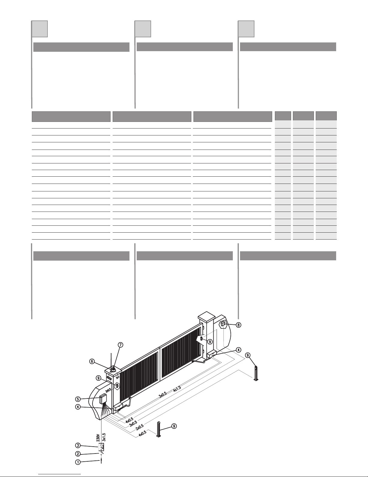
QUADRO D'INSIEME DIBUJO DE CONJUNTOVUE D'ENSEMBLE
1.Linea dialimentazione
2.Interruttore generale
3.Interruttore differenziale
4.ARM
5.Box concentralina
6.Antenna
7.Lampeggiatore
8.Selettore achiave
9.Fotocellule
1. Ligned'alimentation
2. Interrupteurgénéral
3. Disjoncteurdifférentiel
4.ARM
5. Coffret aveclogique decommande
6.Antenne
7. Clignotant
8. Sélecteurà clé
9. Photocellules
1.Línea dealimentación
2.Interruptor general
3.Interruptor diferencial
4.ARM
5.Caja concentralita
6.Antena
7.Luz intermitente
8.Selector dellave
9.Fotocélulas
Tensione di alimentazione
Encoder
Fine-corsa elettrici interni
Lunghezza massima anta
Peso massimo anta
Coppia nominale
Corrente max assorbita
Potenza max assorbita
Condensatore
Movimento irreversibile
Angolo max. di rotazione
Tempo apertura 90°
Temperatura di funzionamento
Intervento termoprotezione
Grado di protezione
Grasso motore
Intermittenza lavoro
Tension d'alimentation
Encodeur
Fins de course électriques incorporés
Longueur maximum vantail
Poids maximum vantail
Couple nominal
Courant max. Absorbé
Puissance max. Absorbée
Condensateur
Mouvement irréversible
Angle max. de rotation
Temps d'ouverture 90°
Température de fonctionnement
Intervention protection thermique
Indice de protection
Graisse moteur
Intermittence travail
Tensión de alimentación
Encoder
Fines de carrera eléctricos internos
Longitud máxima de la hoja
Peso máximo de la hoja
Par nominal
Corriente máx. Absorbida
Potencia máx. Absorbida
Condensador
Movimiento irreversible
Ángulo máx. de rotación
Tiempo de apertura 90°
Temperatura de funcionamiento
Activación protección térmica
Grado de protección
Grasa motor
Intermitencia de funcionamiento
V
-
-
mm
Kg
Nm
A
VA
uF
-
(°)
sec
°C
°C
IP
-
%
230 ac
Si/Yes
Si
2000
250
500
1.9
400
10
Si
130
20*
-20+70
150
44
Ts10
30
/Yes
/Yes
24 dc
Si
Si
2000
250
385
5
120
-
Si
130
20*
-20+70
-
44
Ts10
60
/Yes
/Yes
/Yes
Page 3
2
GB D NL
ARM: Irreversible electromechanical gearmotor with
manual release.Single phase 230 Vac power supply,
built-in electrical limit switches and output for
encoder.
ARM24: Irreversible electromechanical gearmotor
with manual release. Single phase 24 Vdc power
supply, built-in electrical limit switches and output for
encoder.
ARM: Selbsthemmender elektromechanischer Antrieb
mit manuellerEntriegelung. Einphasenstromversorgung
230 V AC, eingebaute elektrische Endschalter und
Encoder-Ausgang.
ARM24: Selbsthemmender elektromechanischer
Antrieb mit manueller Entriegelung. Stromversorgung
24 V DC, eingebaute elektrische Endschalter und
Encoder-Ausgang.
ARM: onomkeerbare elektromechanische
reductiemotor met handbediende ontgrendeling.
Monofase stroomvoorziening 230 Vac, ingebouwde
elektrischeeindschakelaars enuitgang voorEncoder.
ARM24: onomkeerbare elektromechanische
reductiemotor met handbediende ontgrendeling.
Stroomvoorziening 24 Vdc ingebouwde elektrische
eindschakelaarsen uitgangvoor Encoder.
FEATURES MERKMALE KENMERKEN
DATI TECNICI TECHNISCHE DATEN
TECHNISCHE GEGEVENS
ARM24U.M. ARM
* mayvary dueto weight anddimensions ofleaf. * kann jenach Gewicht undGröße des Torflügels variieren. * kunnen verschillenop grond vanhet gewicht en deafmetingen van
de vleugel.
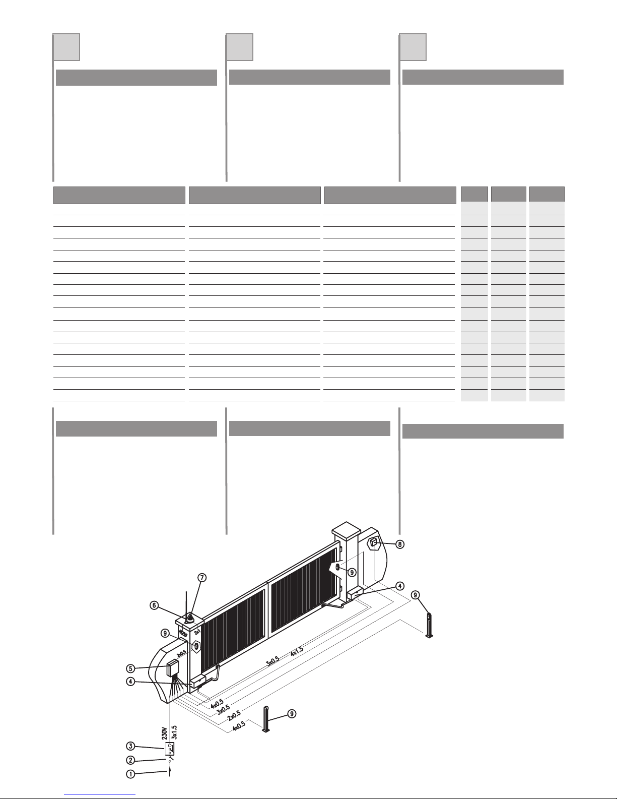
OVERALL LAYOUT
OVERZICHTSTEKENING
GESAMTANSICHT
1.Power line
2.Main switch
3.Differential switch
4.ARM
5.Box withcontrol unit
6.Antenna
7.Flashing light
8.Key-operated selectorswitch
9.Photocells
1. Versorgungsleitung
2. Hauptschalter
3. Differentialschalter
4.ARM
5. Boxmit Steuerung
6.Antenne
7. Blinkleuchte
8. Schlüsseltaster
9. Fotozellen
1.Leiding stroomvoorziening
2.Hoofdschakelaar
3.Differentiaalschakelaar
4.ARM
5.Kastje metbesturingseenheid
6.Antenne
7.Knipperlicht
8.Sleutelschakelaar
9.Fotocellen
Power supply voltage
Encoder
Internal electrical limit switches
Maximum leaf length
Maximum leaf weight
Nominal torque
Max. absorbed current
Max. absorbed power
Capacitor
Irreversible movement
Max. angle of rotation
90° Opening time
Operating temperature
Thermal cutout trip
Protection rating
Motor grease
Work intermittence
Versorgungsspannung
Encoder
Interne elektrische Endschalter
Höchstlänge Torflügel
Höchstgewicht Torflügel
Nenndrehmoment
Höchststromaufnahme
Höchstleistungsaufnahme
Kondensator
Selbsthemmung
Maximaler Drehwinkel
Öffnungszeit 90°
Betriebstemperatur
Auslösung des Wärmeschutzes
Schutzart
Motorfett
Betriebsintermittenz
Voedingsspanning
Encoder
Interne elektrische eindschakelaars
Max. lengte vleugel
Max. gewicht vleugel
Nominaal koppel
Max. opgenomen stroom
Max. opgenomen vermogen
Condensator
Onomkeerbare beweging
Max. draaihoek
Tijd opening 90°
Werkingstemperatuur
Inwerkingtreding motorbeveiliging
Beschermingsklasse
Motorvet
Bedrijfsperiodiciteit
V
-
-
mm
Kg
Nm
A
VA
uF
-
(°)
sec
°C
°C
IP
-
%
230 ac
Yes/Ja
2000
250
500
1.9
400
10
130
20*
-20+70
150
44
Ts10
30
Yes/Ja
Yes/Ja
24 dc
2000
250
385
5
120
-
130
20*
-20+70
-
44
Ts10
60
Yes/Ja
Yes/Ja
Yes/Ja
Page 4
4
IFE
Primadi passareall'installazione assicurarsiche:
1.La strutturadel cancellosia solidaed appropriata.
2. Le cerniere di supporto dell'anta non presentino
segnidi cedimentoe/o irregolarità.
3. Il movimento dell'anta durante tutta la corsa sia
senzapunti diattrito ovibrazioni.
4. La corsa dell'antasia limitata, in apertura ed in
chiusura, da arresti rivestiti in gomma
saldamentefissati alsuolo.
Avantd'effectuer l'installation,s'assurer que:
1. Lastructure duportail est solideet adaptée;
2. Les charnières de support du vantail ne présentent
pas designes d'usureet/ou ni dedéfauts ;
3. Le mouvement du vantail durant toute la course ne
présente aucunpoint defrottement ni devibration ;
4. La course du vantail est limitée, en ouverture et
en fermeture, par des butées revêtues de
caoutchouc solidementfixées ausol.
Antesde comenzarla instalación,controle que:
1.La estructurade lacancela seafirme yadecuada.
2. Las bisagras de soporte de la hoja no tengan
marcasde aflojamientoni irregularidades.
3. El movimiento de la hoja no tenga puntos de
fricciónni vibracionesdurante todasu carrera.
4. La carrera de la hoja debe estar limitada, tanto
en la apertura como en el cierre, por topes
revestidos de goma fijados perfectamente al
suelo.
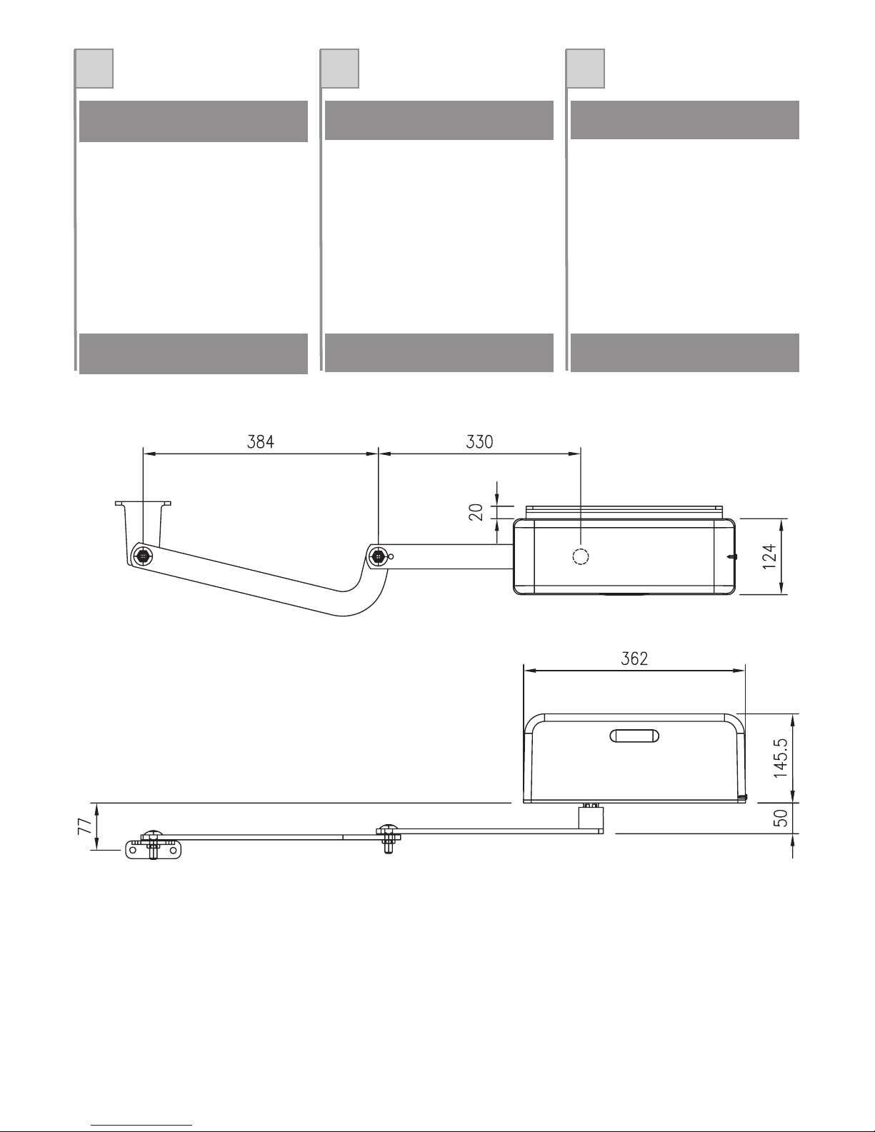
MISURE D'INGOMBRO (mm) DIMENSIONS D'ENCOMBREMENT
(MM)
MEDIDAS EXTERIORES MÁXIMAS
(mm)
Fig.2 /Abb. 2
VERIFICHE PRELIMINARI CONTRÔLES PRÉLIMINAIRES CONTROLES PRELIMINARES
Page 5

5
GB D NL
Beforeinstallation, ensurethat:
1. The gate structure is solid and suited to the
installation.
2. The leaf hinges are not subject to wear and/or
irregularities.
3. Leaf movement is not subject to friction or
vibrationsthroughout travel.
4. Leaf travel is limited, on opening and closing,
byrubber-faced stopsanchored tothe ground.
Fig.2 /Abb. 2
Vorder Installationist sicherzustellen,dass
1. dieTorstruktursolide undgeeignet ist.
2. die Scharniere, die die Torflügel halten, keine
Anzeichen auf nachgebendes Material und/oder
Unregelmäßigkeiten aufweisen.
3. das Tor sich im gesamten Lauf ohne Reibungen
oder Vibrationen bewegt.
4. der Torlauf sowohl beim Öffnen als auch beim
Schließen durch mit Gummi ummantelte
Endanschläge begrenzt wird. Die Anschläge
müssen festim Bodenverankert sein.
Voordatu met installerenbegint, dient uzich ervan te
verzekerendat:
1. De structuur van de poort stevig en voor het
gebruiksdoelgeëigend is.
2. De draagscharnieren van de vleugel geen tekens
vanbreuk en/ofonregelmatigheden vertonen.
3. De bewegingvan de vleugel gedurende de gehele
cycluszonder wrijvingenof trillingenverloopt.
4. De beweging van de vleugel, zowel bij het
openen als het sluiten, begrensd wordt door
met rubber beklede stops die stevig aan de
grondzijn verankerd.
OVERALL DIMENSIONS (mm) ABMESSUNGEN (mm) BUITENMATEN (mm)
PRELIMINARY CHECKS ÜBERPRÜFUNGEN UND
VORBEREITUNGEN
CONTROLES VOORAF
Page 6
6
IFE
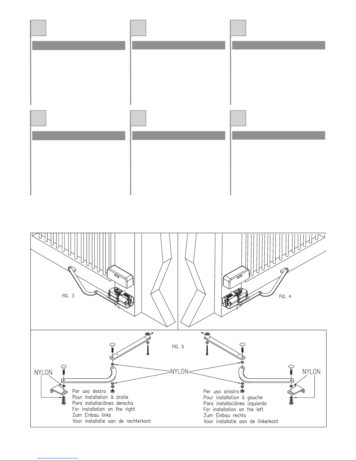
I motoriduttori della serie ARM vengono forniti per
installazioni su colonne alla destra della via d'uscita
Fig. 3. In caso d'installazione alla sinistra della via
d'uscita, è necessario ruotare il motoriduttoredi 180°
e portarlo in posizione come da Fig. 4. Sarà
necessario montare il braccio articolato come
indicatoin Fig.5.
Les opérateurs de la série sont fournis pour des
installations surcolonnes àla droite dela voiede sortie
(fig. 3).En cas d'installation à la gauche de la voie de
sortie, il est nécessaire de tourner l'opérateur de 180°
et dele positionnercomme indiquésur lafig. 4.Il faudra
monter lebras articulécomme indiqué surla figure5.
Los motorreductores de la serie ARM se entregan
para ser instalados en columnas, a la derecha de la
vía desalida comose muestraen laFig. 3. En el caso
de instalacióna laizquierda de la vía desalida, habrá
que girar el motorreductor 180° y colocarlo en la
posición indicada en la Fig. 4. Habrá que montar el
brazoarticulado, talcomo indicadoen laFig. 5.
PROCEDURA DI MONTAGGIO PROCÉDURE DE MONTAGE PROCEDIMIENTO DE MONTAJE
GB D NL
The gearmotors in the series ARM are supplied for
installation onposts tothe rightof the exit point (fig.3.
In the case of installation to the left of the exit point,
the gearmotor must be rotated through 180°, and
positioned as shown in Fig. 4. The articulated arm
shouldalso bemounted, asshown inFig. 5.
DieAntriebe der SerieARM werden zurInstallation auf
Pfosten rechts vom Durchgang geliefert Abb.3. Im
Falle einer Installation auf der linken Seite des
Durchgangs muss der Antrieb um 180° gedreht
werden undwie aufAbb. 4 gezeigtpositioniert werden.
Der Gelenkarmist wieauf Abb.5 gezeigtzu montieren.
De reductiemotoren van de serie ARM worden
geleverd voor installatie op zuilen rechts van de afrit
Afb. 3. In geval van installatie aan de linkerkant van
de afrit, dient de reductiemotor 180° te worden
gedraaid en in de positie te worden gebracht die te
zien is op Afb. 4. De gelede arm moet gemonteerd
wordenzoals aangegevenopAfb. 5.
ASSEMBLY PROCEDURE MONTAGEVERFAHREN MONTAGEPROCEDURE
Page 7

A
50
100
150
200
250
B
50
100
50
100
50
100
500
100
50
C
120
120
120
120
120
120
120
120
120
X
450
440
470
450
480
470
490
470
500
Z
590
590
590
590
580
580
570
570
560
7
IFE
Nella tabella e in Fig. 6 compaiono alcuni tipi di
applicazioneper losviluppo diaperture finoa 90°.
NOTA: Le misure sono indicative, solo perpreparare
l'installazione. Verificare quale delle possibili
soluzioni può essere applicata al vostro caso, e
provare manualmente l'applicazione prima di
procedereal fissaggiodella piastrao dellestaffe
Le tableau ci-dessouset la fig. 6 contiennentplusieurs
types d'applications pour le développement
d'ouvertures jusqu'à90°.
NOTE: les mesures sontindicatives, uniquement pour
préparer l'installation. Vérifier, parmi les solutions
possibles, qu'elle estcelle qui s'applique àvotre cas et
essayer manuellement l'application avant d'effectuer
la fixationde laplaque et despattes.
En la tabla y en la Fig. 6 se indican algunos tipos de
aplicación para el desarrollo de aperturas de hasta
90°.
NOTA: las medidas son indicativas sólo para
preparar la instalación. Controle las posibles
soluciones quepuedan serútiles parausted ypruebe
manualmente la aplicaciónantes defijar laplaca o los
estribos.
INSTALLAZIONE INSTALLATION INSTALACIÓN
GB D NL
The table and Fig. 6 show a number of application
optionsfor openingsup to90°.
NOTE: Measurements are guideline only, for
preliminary installation procedures. Check which
application is most suited to the installation required,
and manually test the application before fixing the
plateor brackets.
In der Tabelle und auf Abb. 6 sind einige
Anwendungsarten fürÖffnungenbis zu90° zusehen.
ANMERKUNG: Die Maße sind unverbindlich und
dienen zur Vorbereitung der Installation. Es ist zu
überprüfen, welche der möglichen Lösungen im
konkreten Fall angewandt werden kann,dazu wird die
Anwendung zuerst manuell ausprobiert, bevor die
Platte oderdie Bügelbefestigt werden.
In de tabel en op Afb. 6 ziet u enkele
toepassingstypes voor de realisatie van openingen
totaan 90°.
N.B.: de afmetingen zijn louter indicatief, om de
installatie voor te bereiden. Controleer welke van de
mogelijke oplossingen in uw geval kan worden
toegepast, en probeer de toepassing metde hand uit
alvorensde plaatof debeugels vastte zetten.
INSTALLATION INSTALLATION INSTALLATIE
Dimensionsin (mm)
Abmessungenin (mm)
Afmetingenin (mm)
Fig.6 /Abb. 6
Page 8

8
IFE
MONTAGGIO MONTAGE MONTAJE
01.Togliereil tappocopri sblocco(A)
02.Allentare le viti(B) esfilare ilcoperchio (C)
03. Svitare le viti e i dadi (D) e togliere il motoriduttore
dallapiastra diancoraggio (E).
04. Fissare la piastra di ancoraggio (E) in posizione
prescelta, con 4 tasselli ad espansione o quando è
possibiletramite saldaturaalla colonnaportante.
05.Rimontare ilmotoriduttore eserrare leviti edadi (D).
06. Montare il braccio articolato assemblato (F) sul
motoriduttore fissandolo con la vite (G) ed il grano
(H).
07. Sbloccare il motoriduttore conl'apposita chiave (I) e
sistemare il braccio totalmente aperto, sull'anta del
cancellochiuso (Fig.8).
08. Determinarequindi laposizione dellastaffa anteriore
e spostarsi di 10mm verso il motoriduttore come
indicatoin Fig.8.
09. Fissare in questa posizione la staffa anteriore con
adeguateviti difissaggio otramite saldatura.
10. Regolarein modo appropriatole camme difinecorsa
(L).
11.Inserire ilcoperchio (C)e fissarele viti(B).
12. Ribloccare il motoriduttore ed inserire il tappo copri
sblocco(A).
01.Enlever lebouchon de protectiondu débrayage(A) ;
02.Desserrer lesvis (B)et retirerle couvercle(C) ;
03. Dévisser les vis et les écrous (D) et enlever
l'opérateurde laplaque d'ancrage (E);
04. Fixerla plaque d'ancrage(E) dans laposition voulue
avec 4 chevillées expansion où, quand cela est
possible,en lasoudant àla colonneportante ;
05. Remonter l'opérateur et serrer les vis et les écrous
(D);
06. Monter le bras articulé assemblé (F) sur l'opérateur
etle fixeravec lavis (G)et legoujon (H);
07. Débrayer l'opérateur avec la clé (I) et positionner le
bras complètement ouvert sur le vantail du portail
fermé(fig. 8);
08. Définir ensuite la position de la patte avant et se
déplacer de 10 mm vers l'opérateur comme indiqué
surla fig.8 ;
09. Fixer la patte avant dans cette position avec des vis
defixation adéquatesou parsoudage.
10. Régler de manière adéquate les cames de fin de
course(L) ;
11.Positionner lecouvercle (C)et fixerles vis(B);
12. Rebloquer l'opérateur et remettre en place le
bouchonde protectiondu débrayage (A).
01. Quite el tapónque cubre el dispositivo dedesbloqueo
(A).
02.Afloje lostornillos (B)y extraigala tapa(C).
03. Desenrosque los tornillos y las tuercas (D) y quite el
motorreductorde laplaca defijación (E).
04. Fijela placade fijación (E)en laposición escogidacon
4tacos deexpansióno, cuandoseaposible, soldadaa
lacolumna portadora.
05. Monte nuevamente el motorreductor y apriete los
tornillosy lastuercas (D).
06. Monte el brazo articulado ensamblado (F) en el
motorreductor,fijándolo conel tornillo(G) yel pasador
(H).
07. Desbloquee el motorreductor con la llave
correspondiente (I) y acomode el brazo totalmente
abiertosobre lahoja dela cancelacerrada (Fig.8).
08.Determine laposición dela placaanterior ydesplácese
10 mmhacia el motorreductor, talcomo semuestra en
laFig. 8.
09. Fijeen estaposición laplaca delanteracon tornillosde
fijaciónadecuados osoldándola.
10.Regule adecuadamentelas levasde finde carrera(L).
11.Monte latapa (C)y fijelos tornillos(B).
12. Bloquee nuevamente el motorreductor y coloque el
tapónque cubreel dispositivode desbloqueo(A).
Fig. 7 / Abb. 7
Fig. 8 / Abb. 8
Fig. 8A /Abb. 8A
*IMPORTANTE!
Accertarsi che durante il normale funzionamento, a
cancello chiusoil perno 1non tocchi la sede 2,vedi
figura8A.
*IMPORTANT!
Contrôler que durant le fonctionnement normal,
avec le portail fermé, le pivot 1 ne touche pas le
logement2, voirfigure 8A.
*IMPORTANTE!
Asegúrese de que durante el funcionamiento
normal, con la cancela cerrada, el perno 1 no toque
elalojamiento 2,véase la figura8A.
Page 9

9
GB D NL
ASSEMBLY MONTAGE MONTAGE
01.Remove therelease cap (A)
02.Loosen screws(B) and removethe cover(C)
03. Loosen the screws and nuts (D) and remove the
gearmotorfrom theanchoring plate(E).
04. Fix the anchoring plate (E) in the selected position,
with 4expansion plugs or, whenpossible, bywelding
ITto thesupport post.
05. Re-fitthe gearmotor andtighten the screwsand nuts
(D)fully down.
06. Mount the assembled articulated arm (F) on the
gearmotorby meansof screw(G) andstud bolt(H).
07. Release the gearmotor by meansof the relative key
(I) andplace the arm in the fully openposition on the
leafof theclosed gate (Fig.8).
08. Select the position of the front bracket and move by
10mm towardsthe gearmotor, asshown inFig. 8.
09. Fix the front bracket in this position by means of
suitablefixing screwsor bywelding.
10.Adjust the limitswitch cams(L) asrequired.
11.Insert cover(C) andtighten screws(B).
12.Re-lock thegearmotor and insertrelease cap(A).
01. Den Verschluss an der Entriegelungsabdeckung (A)
entfernen.
02.Die Schrauben(B) lösenund denDeckel(C) entfernen.
03. Die Schrauben und Muttern (D) herausschrauben und
denAntrieb vonderVerankerungsplatte(E) lösen.
04. Die Verankerungsplatte (E) mit 4 Spreizdübeln an der
gewünschten Stelle anbringen oder, wo möglich,direkt
aufden tragendenPfosten schweißen.
05. Den Antrieb wieder einbauen und die Schrauben und
Muttern(D) anziehen.
06. Den zusammengebauten Gelenkarm (F) am Antrieb
einbauen und mit der Schraube (G) und der
Stiftschraube(H) befestigen.
07. Den Antrieb mit dem speziellen Schlüssel (l) entriegeln
und den vollständig geöffneten Gelenkarm bei
geschlossenemToram Torflügel befestigen(Abb.8).
08. Anschließend die Position des vorderen Bügels
bestimmen und wie aufAbb. 8 gezeigt 10 mm weiter in
RichtungAntrieb verschieben.
09. Den vorderen Bügel mit geeigneten Schrauben oder
durchSchweißen indieser Positionfixieren.
10. Die Nocken des Endschalters (L) entsprechend
einstellen.
11. Den Deckel (C) einsetzen und die Schrauben (B)
anziehen.
12. Den Antrieb wieder verriegeln und den Verschluss der
Entriegelungsabdeckung(A) einsetzen.
01.Verwijderde afdekdopvande ontgrendeling(A)
02.Draai deschroeven (B)los enverwijderde afdekking(C)
03. Draaide schroevenen demoeren (D)los enverwijder de
reductiemotorvan deverankeringplaat (E).
04. Bevestig de verankeringplaat (E) in degekozen positie,
met 4expansiepluggen of,wanneer dit mogelijkis, door
hemvast telassen aande dragendezuil.
05. Plaats de reductiemotor terug en haal de schroeven en
demoeren (D)aan.
06. Monteer de geassembleerde gelede arm (F) op de
reductiemotor enzet hemvast metde schroef(G) ende
stift(H).
07. Ontgrendelde reductiemotor metde hiervoor bestemde
sleutel (I) en plaats de volledig geopende arm op de
vleugelvan degesloten poort(Afb.8).
08. Bepaal vervolgens de positie van de voorbeugel en
verplaats hem 10 mm in de richting van de
reductiemotor,zoals aangegevenopAfb.8.
09. Zet de voorbeugel in deze positie vast met geschikte
bevestigingsschroevenof doorlassen.
10.Stel deeindschakelaarnokken (L)correct af.
11.Plaats deafdekking (C)en draaide schroeven(B) vast.
12.Vergrendelde reductiemotorweer enplaats deafdekdop
vande ontgrendeling(A) terug.
Fig. 7 / Abb. 7
Fig. 8 / Abb. 8
Fig. 8A /Abb. 8A
*IMPORTANT!
During normal operation, ensure thatwhen the gate
is closed pin 1 does not touch seat 2, as shown in
figure8A.
*WICHTIG!
Sicherstellen, dass bei normalem Betrieb und
geschlossenem Tor der Bolzen 1 nicht den Sitz 2
berührt,siehe Abbildung8 A.
*BELANGRIJK!
Vergewis u ervan dat bij normale werking bij
gesloten poort pin 1 de ruimte 2 niet aanraakt, zie
afbeelding8A.
Page 10

10
IFE
Les operateursARM sont pre-cabléscomme détaillé sur
la fig. 9A. Brancher les cables du moteur à la centrale
(utiliser un cable d'au moins 1.5mmq.) et les cables de
l'encoder (utiliserun cable blindéd'au moins 3x0.25).
pour les connexions de
l'encodeur, nous conseillons d'utiliser un câble blindé
d'une longueurmaximum de10 mètres.
N'utiliser en aucun cas un câble multipôle pour faire
passer ensemble les connexions du moteur et de
l'encodeur !
Notes importantes:
Los motoreductoresARM son pre-cableados comoen
fig. 9A. Cablear a la central, los cables motor (usar un
cable de al menos 1.5mmq.) y los cables del encoder
(usarun cableescudado deal menos3x0.25).
para conectar el encoder se
aconseja utilizar un cable blindado que no mida más
de10 metros.
No utilice por ningúnmotivo un cable multipolar para
pasarjuntas lasconexiones delmotor ydel encoder.
Notas importantes:
COLLEGAMENTI ELETTRICI ARM
(230V)
BRANCHEMENTS ÉLECTRIQUES
ARM (230 V)
CONEXIONES ELÉCTRICAS ARM
(230V)
I motoriduttori ARM sono pre-cablati come in fig. 9A.
Collegare allacentrale icavi motore(usare uncavo di
almeno 1.5mmq.)e icavi dell'encoder(usare uncavo
schermatodi almeno3x0.25).
per i collegamenti dell'encoder
consigliamo di usareun cavoschermato dilunghezza
nonsuperiore a10 metri.
Non usare assolutamente un cavo multipolo per far
passare assieme i collegamenti del motore e
dell'encoder!
Note importanti:
Fig. 9A /Abb. 9A Fig. 9B / Abb. 9B
ATTENTION!
Si c'est notre logique decommande T100 ou T101 qui
est montée, il ne faut pas utiliser les fins de course.
Déplacer les cames de sorte qu'elles n'interviennent
jamais durantle fonctionnement.
Si l'on souhaite utiliser les fins de course (directement
raccordés dans la logique de commande), il faut
modifier les connexions de l'opérateurcomme indiqué
sur lafigure 9B:
- débrancher les fils raccordés aux bornes (C) et les
connecter àla borne(A) ;
- déplacer les deux paires de fils raccordées aux
bornes (B)sur lesbornes (C)
¡ATENCIÓN!
Si se utiliza nuestra central T100 o T101, no deben
utilizarse los finesde carrera.Desplacelas levaspara
quenunca intervengandurante elfuncionamiento.
Si desea utilizar los fines de carrera (conectados
directamente a la central), modifique las conexiones
delmotorreductor,tal comose muestraen lafigura 9B:
- desconecte los cables conectados a los bornes
(C)y conéctelosjuntos enel borne(A).
- desplace los dos pares de cables conectados en
losbornes (B)a losbornes (C).
ATTENZIONE!
Nel casovenga usata la nostra centrale T100oppure
T101, non devono essere usati i finecorsa. Spostare
quindi le camme in modo che non intervengano mai
duranteil funzionamento.
Se si desiderausare i finecorsa (collegatidirettamente
in centrale) occorre modificare i collegamenti del
motoriduttorecome indicatoin figura 9B:
- scollegare i fili collegati nei morsetti (C) e inserirli
entrambinel morsetto(A)
- spostare le due coppie di fili collegatenei morsetti
(B)nei morsetti(C)
REGOLAZIONE DELLE CAMME
FINECORSA
RÉGLAGE DES CAMES DE FIN DE
COURSE
REGULACIÓN DE LAS LEVAS DE
FIN DE CARRERA
Avec l'opérateur en mode manuel, fermer le portail et
régler la came supérieure de manière à provoquer
l'intervention du microinterrupteur. Ensuite, ouvrir le
portail et régler la came inférieure de manière à
provoquer l'intervention du second microinterrupteur
(voir détailsLsur lafigure 7).
Con el motorreductor en funcionamiento manual,
coloque lacancela en la posición decierre y regulela
leva
superior demanera que elmicrointerruptor se active.
Posteriormente, abra la cancela y regule la leva
inferior para que active el segundo microinterruptor
(véasedetalle Len lafigura 7)
Con il motoriduttore in funzionamento manuale,
portare in chiusura il cancello e regolare la camma
superiore in modo che faccia scattare il
microinterruttore. Successivamente aprire il
cancello e regolare la camma inferiore in modoche
scatti il secondo microinterruttore (vedi particolari L
di figura 7)
Page 11

11
GB D NL
Die Motoren ARM, sind vorverkabelt wie auf fig. 9A.
Die Motorenkabel (einen Kabelvon Minimum 1,5mmq
benutzten) und die Enkoderkabel (einen Schirmkabel
von Minimum 3x0.25 benutzen) an die Steuerung
verbinden.
Für denAnschluss des Encoders
empfehlen wir ein geschirmtes Kabel von nicht mehr
als 10m Länge.
Keinesfalls ein Vielfachkabel verwenden, um die
Motor- und die Encoderanschlüsse zusammen
durchzuführen.
Wichtige Hinweise:
De aandrijving ARM is al van bedrading voorzien
zoals infig. 9A.Sluit dekabels vande aandrijvingaan
op de besturing: motor kabel (minimale draadsectie
1,5mm²) en encoder kabel (afgeschermd, minimale
draadsectie3x0.25mm²).
voor de aansluitingen van de encoder
wordt aanbevolen een afgeschermde kabel met een
lengtevan maximaal10 meterte gebruiken.
Gebruik absoluut geen meerpolige kabel om de
aansluitingen van de motor en de encoder samen
doorte voeren!
Belangrijk:
ARM ELECTRICAL CONNECTIONS
(230 V)
ELEKTRISCHE ANSCHLÜSSE ARM
(230 V)
ELEKTRISCHE AANSLUITINGEN
ARM (230V)
The gear motors ARM are pre-wired as in fig. 9A.
Connect to control unit the motor's cables (use a
cable at least 1.5mmq.) and the encoder's cables
(usea screenedcable atleast 3x0.25).
for encoder connections, a
shielded cable is recommended, with a length of
maximum10 metres.
Never use a multi-pole cable to route motor and
encoderconnections together!
Important notes:
Fig. 9A /Abb. 9A Fig. 9B / Abb. 9B
ACHTUNG!
Falls unsere Steuerung T100 oder T101 verwendet
werden, dürfen die Endschalter nicht eingesetzt
werden. Daher sind die Nocken so zu verstellen, dass
sie niein denBetrieb eingreifen.
Falls die Endschalter eingesetzt werden sollen
(Direktanschluss an der Steuerung), sind die
Anschlüsse des Antriebs wie auf Abbildung 9B
gezeigt zuändern:
- die an die Klemmen (C) angeschlossenen Leiter
lösen undbeide indie Klemme (A)einstecken
- die zwei an die Klemmen (B) angeschlossenen
Leiterpaare aufdie Klemmen(C) verlegen
LETOP!
Indien onzebesturingseenheid T100 ofT101 worden
gebruikt, moeten er geen eindschakelaars gebruikt
worden. De nokken dienen in dit geval verplaatst te
worden, zodat ze gedurende de werking niet
geactiveerdkunnen worden.
Als u de eindschakelaars (rechtstreeks in de
besturingseenheid aangesloten) wenst te gebruiken,
dienen de aansluitingen van de reductiemotor te
wordengewijzigd, zoalsaangegeven opafbeelding 9B:
- koppel de op deklemmen (C) aangeslotendraden
afen steekze allebeiin deklem (A)
verplaats de twee draadkoppels die zijn aangesloten
opde klemmen(B) naarde klemmen(C).
-
CAUTION!
If using control unit models T100 or T101,do not use
limit switches. Therefore in this case move the cams
sothat theynever engageduring operation.
If limit switchesare required(connected directlyto the
control unit) modifythe connections of thegearmotor
asshown infigure 9B.
- disconnect the wires connected to terminals (C)
andinsert bothin terminal(A)
- move the twopairs ofwires connected to terminals
(B)to terminal(C)
ADJUSTING THE LIMIT SWITCH
CAMS
EINSTELLUNG DER
ENDSCHALTERNOCKEN
AFSTELLING VAN DE
EINDSCHAKELAARNOKKEN
Den Antrieb auf manuellen Betrieb stellen, das Tor
schließen undden oberenNocken so einstellen,
dass er den Mikroschalter auslöst. Danach das Tor
wieder öffnen und den unteren Nocken so einstellen,
dass er den Mikroschalter auslöst (siehe Details L auf
derAbb. 7).
Met dereductiemotor inhandbediende werking laat u
de poortsluiten en steltu de bovenste nok zodanigaf
dat hij de microschakelaar activeert Laat de poort
vervolgens openen en stel de onderste nok zodanig
af dat de tweede microschakelaar geactiveerd wordt
(ziedetails Lvan afbeelding7) .
With the gearmotor operating in manual mode,
activategate closingand adjustthe uppercam
so that the microswitch trips. Thenopen the gateand
adjust the lower cam so that the second microswitch
trips(see detailsLin figure7).
Page 12

12
24V
M
D
ENCODER
M
24V
COM.
FINE-CORSA
A
B
24V
M
D
ENCODER
M
24V
A
B
Fig. 9D / Abb.9DFig. 9C / Abb.9C
IFE
Les operateursARM sont pre-cabléscomme détaillé sur
la fig. 9C. Brancher les cables du moteur à la centrale
(utiliser un cable d'au moins 2.5mmq.) et les cables de
l'encoder (utiliserun cable blindéd'au moins 3x0.25).
pour les connexions de
l'encodeur, nous conseillons d'utiliser un câble blindé
d'une longueurmaximum de10 mètres.
Notes importantes:
Los motoreductores ARM son pre-cableados comno
en fig. 9C. Cablear a la central, los cables del motor
(usar un cable de al menos 2.5mmq.) y los cables del
encoder(usar uncable escudadode almenos 3x0.25).
para conectar el encoder se
aconseja utilizar un cable blindado que no mida más
de10 metros.
Notas importantes:
COLLEGAMENTI ELETTRICI
ARM24 (24V)
BRANCHEMENTS ÉLECTRIQUES
ARM24 (24 V)
CONEXIONES ELÉCTRICAS
ARM24 (24V)
I motoriduttori ARM sono pre-cablati come in fig. 9C.
Collegare allacentrale icavi motore(usare uncavo di
almeno 2.5mmq.)e icavi dell'encoder(usare uncavo
schermatodi almeno3x0.25).
per i collegamenti dell'encoder
consigliamo di usareun cavoschermato dilunghezza
nonsuperiore a10 metri.
Note importanti:
ATTENTION!
Si l'on souhaite utiliser les fins de course (directement
raccordés dans la logique de commande), il faut
modifier les connexions de l'opérateur comme
indiqué surla figure9D :
- éliminer les deux diodes de redressement raccordées
dans lebornier ;
- déplacer les fils raccordés à la borne (B) sur la borne
(A);
- déplacer lefil raccordé àla borne(A) surla borne(B).
¡ATENCIÓN!
Si desea utilizar los fines de carrera (conectados
directamente a la central), modifique las conexiones
delmotorreductor,tal comose muestraen lafigura 9D:
- elimine los dos diodos rectificadores conectados
enla regleta
- desplace los cables conectados en el borne(B) al
borne(A)
- desplace el cable conectado en el borne (A) al
borne(B)
ATTENZIONE!
Se si desiderausare i finecorsa (collegatidirettamente
in centrale) occorre modificare i collegamenti del
motoriduttorecome indicatoin figura 9D:
- eliminare i due diodi raddrizzatori collegati in
morsettiera
- spostarei filicollegati nelmorsetto (B)nel morsetto(A)
- spostare il filo collegato nel morsetto (A) nel
morsetto(B)
REGOLAZIONE DELLE CAMME
FINECORSA
RÉGLAGE DES CAMES DE FIN DE
COURSE
REGULACIÓN DE LAS LEVAS DE
FIN DE CARRERA
Avec l'opérateur en mode manuel, fermer le portail et
régler la came supérieure de manière à provoquer
l'intervention du microinterrupteur. Ensuite, ouvrir le
portail et régler la came inférieure de manière à
provoquer l'intervention du second microinterrupteur
(voir détailsLsur lafigure 7).
Con el motorreductor en funcionamiento manual,
coloque lacancela en la posición decierre y regulela
leva
superior demanera que elmicrointerruptor se active.
Posteriormente, abra la cancela y regule la leva
inferior para que active el segundo microinterruptor
(véasedetalle Len lafigura 7)
Con il motoriduttore in funzionamento manuale,
portare in chiusura il cancello e regolare la camma
superiore in modo che faccia scattare il
microinterruttore. Successivamente aprire il
cancello e regolare la camma inferiore in modoche
scatti il secondo microinterruttore (vedi particolari L
di figura 7)
Page 13

13
GB D NL
Die Motoren ARM, sind vorverkabelt wie auf fig. 9C.
Die Motorenkabel (einen Kabelvon Minimum 2,5mmq
benutzten) und die Enkoderkabel (einen Schirmkabel
von Minimum 3x0.25 benutzen) an die Steuerung
verbinden.
Für denAnschluss des Encoders
empfehlen wir ein geschirmtes Kabel von nicht mehr
als 10m Länge.
Wichtige Hinweise:
De aandrijving ARM is al van bedrading voorzien
zoals infig. 9C. Sluitde kabelsvan de aandrijvingaan
op de besturing: motor kabel (minimale draadsectie
2,5mm²) en encoder kabel (afgeschermd, minimale
draadsectie3x0.25mm²).
voor de aansluitingen van de encoder
wordt aanbevolen een afgeschermde kabel met een
lengtevan maximaal10 meterte gebruiken.
Belangrijk:
ARM24 ELECTRICAL
CONNECTIONS (24V)
ELEKTRISCHE ANSCHLÜSSE
ARM24 (24 V)
ELEKTRISCHE AANSLUITINGEN
ARM24 (24V)
The gear motors ARM are pre-wired as in fig. 9C.
Connect to control unit, the motor's cables (use a
cable at least 2.5mmq.) and the encoder's cables
(usea screenedcable atleast 3x0.25).
for encoder connections, a
shielded cable is recommended, with a length of
maximum10 metres.
Important notes:
ACHTUNG!
Falls die Endschalter eingesetzt werden sollen
(Direktanschluss an der Steuerung), sind die
Anschlüsse des Antriebs wie auf Abbildung 9D
gezeigt zuändern:
- die zwei an der Klemmleiste angeschlossenen
Diodengleichrichter entfernen
- die an der Klemme (B) angeschlossenen Leiter auf
die Klemme(A) verlegen
- den ander Klemme (A)angeschlossenen Leiter auf
die Klemme(B) verlegen.
LETOP!
Als u de eindschakelaars (rechtstreeks in de
besturingseenheid aangesloten) wenst te gebruiken,
dienen deaansluitingen van dereductiemotor te worden
gewijzigd,zoals aangegevenop afbeelding 9D:
- elimineer de twee gelijkrichterdiodes die zijn
aangeslotenop deklemmenstrook
- verplaats de draden die zijn aangesloten op de
klem(B) naarde klem(A)
- verplaats de draad die is aangesloten op de klem
(A)naar deklem (B).
CAUTION!
If limit switchesare required(connected directlyto the
control unit) modifythe connections of thegearmotor
asshown infigure 9D:
- remove the two rectifier diodes connected on the
terminalboard
- move the wires connected to terminal (B) to
terminal(A)
- move the wire connected to terminal (A) to
terminal (B).
ADJUSTING THE LIMIT SWITCH
CAMS
EINSTELLUNG DER
ENDSCHALTERNOCKEN
AFSTELLING VAN DE
EINDSCHAKELAARNOKKEN
Den Antrieb auf manuellen Betrieb stellen, das Tor
schließen undden oberenNocken so einstellen,
dass er den Mikroschalter auslöst. Danach das Tor
wieder öffnen und den unteren Nocken so einstellen,
dass er den Mikroschalter auslöst (siehe Details L auf
derAbb. 7).
Met dereductiemotor inhandbediende werking laat u
de poortsluiten en steltu de bovenste nok zodanigaf
dat hij de microschakelaar activeert Laat de poort
vervolgens openen en stel de onderste nok zodanig
af dat de tweede microschakelaar geactiveerd wordt
(ziedetails Lvan afbeelding7) .
With the gearmotor operating in manual mode,
activategate closingand adjustthe uppercam
so that the microswitch trips. Thenopen the gateand
adjust the lower cam so that the second microswitch
trips(see detailsLin figure7).
24V
M
D
ENCODER
M
24V
COM.
FINE-CORSA
A
B
24V
M
D
ENCODER
M
24V
A
B
Fig. 9D / Abb.9DFig. 9C / Abb.9C
Page 14

14
IFE
In situazionidi emergenza(temporanea mancanzadi
alimentazione di rete, cattivo funzionamento etc.),
l'apertura o la chiusura del cancello può avvenire
manualmente.
Estrarre iltappo, inserirela chiavenell'apposita sede,
girarefino asbloccare ilmotoriduttore (fig.10).
Volendo richiudere il cancello e bloccarlo in
situazione ancora d'emergenza sarà sufficiente
ruotarel'apposita chiavedi sbloccoin sensocontario.
A questo punto il blocco avverrà automaticamente
alla prima manovra di chiusura del cancello sia
automaticache manuale.
En cas d'urgence (coupure de courant temporaire,
fonctionnement défectueux, etc.), l'ouverture ou la
fermeture duportail peuts'effectuer manuellement.
Retirer le bouchon, introduire la clé dans la serrure
prévue et tourner jusqu'au débrayage de l'opérateur
(fig. 10).
Pour refermer le portail et le bloquer, toujours en cas
d'urgence, il suffit de tourner la clé de débrayage en
sens inverse.
Le portail sera ensuite automatiquement bloqué à la
première manœuvre de fermeture automatique ou
manuelle.
En situacionesde emergencia (corteimprevisto dela
corriente eléctrica, funcionamiento incorrecto, etc.),
lacancela sepodrá abriro cerrarmanualmente.
Extraiga el tapón,introduzca lallave enel alojamiento
correspondiente, y gírela hasta desbloquear el
motorreductor(fig. 10).
Si hubiera que cerrar la cancela y bloquearla en una
situación de emergencia, habrá que girar la llave de
desbloqueohacia elotro lado.
Entonces, el bloqueo se efectuará automáticamente
en la primera maniobra de cierre de la cancela, sea
éstaautomática omanual.
FUNZIONAMENTO MANUALE FONCTIONNEMENT MANUEL FUNCIONAMIENTO MANUAL
Fig. 10 / Abb. 10
1. Il motoriduttore non apre o non chiude, il
motore elettrico non funziona, non si avverte
alcunrumore ovibrazione.
2. Il motoriduttore non apre, il motore funziona,
manon avvieneil movimento.
3. Il motoriduttore esegue la manovra inversa
(chiusurainvece diapertura).
a. Verificare chela centralina elettronica di comando
sia regolarmente alimentata e che i fusibili siano
efficienti
b. Accertarsi che i collegamenti siano esatti e le
cammeregolate correttamente.
a.Verificare il dispositivodi sbloccomanuale;
b. Assicurarsi che la regolazione della forza sulla
centralinasia stataeseguita correttamente;
c. Assicurarsi che non vi siano impedimenti nel
movimentodell'anta.
a. Invertire fra loro i filidi fasedel motoree verificareil
corretto funzionamento delle camme dei
finecorsa.
1. L'opérateur n'ouvre pas ou ne ferme pas, le
moteur électrique ne fonctionne pas, on
n'entend aucunbruit nivibration.
2. L'opérateur n'ouvre pas, le moteur fonctionne
mais lemouvement nese produit pas.
3. L'opérateur effectue la manœuvre inverse
(fermeture aulieu d'ouverture).
a. Vérifier que la logique de commande électronique
est correctement alimentée et que lesfusibles sont
intacts ;
b. S'assurer que les connexions sont exactes et que
les camessont correctementréglées.
a. Vérifierle dispositifde débrayage manuel;
b. S'assurerque le réglagede laforce sur lalogique de
commande aété correctementeffectué ;
c. S'assurer qu'aucunobstacle ne gêne lemouvement
du vantail.
a. Intervertir les fils de phase dumoteur et vérifier que
les cames de fin de course fonctionnent
correctement.
1. El motorreductor no abre ni cierra, el motor
eléctrico no funciona, no se advierte ningún
ruidoni vibración.
2. El motorreductor no abre, el motor funciona
peroel movimientono seproduce.
3. El motorreductor hace la maniobra inversa
(cierreen lugarde apertura).
a. Controle que la centralita electrónica de mando
esté bien alimentada y que los fusibles sean
eficientes.
b. Controle que lasconexiones sean correctas y que
laslevas esténbien reguladas
a.Controle eldispositivo dedesbloqueo manual.
b. Controle que la fuerza esté bien regulada en la
central.
c. Controle quela hojano tenganingún obstáculoque
impidasu movimiento.
a. Invierta entre sí los cables de fase del motor y
controle que las levas de finde carrera funcionen
correctamente.
ANOMALIE E RIMEDI ANOMALIES ET REMÈDES PROBLEMAS Y SOLUCIONES
Page 15

15
GB D NL
In emergencies (temporary mains power failure,
malfunctions, etc.) the gate can be opened and
closedmanually.
Remove the cap,insert thekey inthe relativeslot, and
turnuntil thegearmotor isreleased (fig.10).
To close the gate and block it in emergency
conditions, simplyturn therelease keyin theopposite
direction.
At this pointthe gate will be blocked automatically on
the first closing manoeuvre either in automatic or
manualmode.
Im Notfall (vorübergehender Netzstromausfall,
Betriebsstörung, usw.) kanndas Tor von Handgeöffnet
und geschlossenwerden.
Den Verschluss entfernen, den Schlüssel einstecken
und drehen,bis derAntrieb entriegeltist (Abb.10).
Den Schlüssel in die entgegengesetze Richtung
drehen, wenn mandas Tor wieder schließen und noch
im Notzustandblockieren will.
Nun wird die Blockierung automatisch bei der ersten
Schließbewegung des Tors erfolgen, die automatisch
oder manuellsein kann.
In noodsituaties(tijdelijke stroomuitval,slechte werking
etc.), kan het openen of sluiten van de poort via
handbedieningplaatsvinden.
Verwijder de dop, steek de sleutel in de hiervoor
bestemde opening en draai de sleutel tot de
reductiemotorontgrendelt (afb.10).
Als u de poort wilt sluiten en vergrendelen terwijl de
noodsituatie nogsteeds van krachtis, ishet voldoende
om de hiervoor bestemde ontgrendelingssleutel in
tegengestelderichting tedraaien.
Op dit punt zal de vergrendeling automatisch
plaatsvindenbij deeerste sluitmanoeuvrevan depoort,
ofdit nuin automatischeof inhandbediende werkingis.
MANUAL OPERATION MANUELLER BETRIEB HANDBEDIENDE WERKING
Fig. 10 / Abb. 10
1. The gearmotor does not open or close, the
electric motor does not work, no noise or
vibrationsare detected.
2. The gearmotor does not open, the electric
motorworks, butno movementoccurs.
3. The gearmotor performs the opposite
manoeuvre(closing insteadof opening).
a. Check that the electronic control unit is powered
correctlyand thatall fusesare efficient.
b. Ensure that the connections are correct and cams
areadjusted correctly
a.Check themanual releasedevice;
b. Ensure that force values are set correctly on the
controlunit;
c. Ensure that there are no obstructions to leaf
movement.
a. Invert the motor phase wires and check correct
operationof thelimit switchcams.
1. Der Antrieb öffnet und schließt nicht, der EMotor funktioniert nicht und man bemerkt
daher wederein Geräuschnoch Vibrationen.
2. Der Antrieb öffnet nicht, der Motor funktioniert
(man hört ein Geräusch), aber es erfolgt keine
Bewegung.
3. DerAntrieb führt dieumgekehrte Bewegung aus
(Schließung stattÖffnung).
a. Sicherstellen, dass die elektronische Steuerung
ordnungsgemäß gespeist wird und die
Sicherungen funktionstüchtigsind.
b. Sicherstellen, dass die Anschlüsse richtig sind und
die Nockenkorrekt eingestelltsind.
a. Diemanuelle Entriegelungsvorrichtungüberprüfen.
b. Sicherstellen, dass die Krafteinstellung auf der
Steuerung korrektausgeführt ist.
c. Sicherstellen, dass keine Hindernisse die
Bewegung desTorflügelsstören.
a. Die Phasenleiter des Antriebs umkehren und den
einwandfreien Betrieb der Endschalternocken
überprüfen.
1. De reductiemotor opent of sluit niet, de
elektromotor werkt niet, er is geen enkel geluid
oftrilling waarte nemen.
2. De reductiemotor opent niet, de motor werkt,
maarer vindtgeen bewegingplaats.
3. De reductiemotor voert de tegengestelde
manoeuvreuit (sluitenin plaatsvan openen).
a. Controleer of de elektronische besturingseenheid
stroomkrijgt enof dezekeringen intactzijn
b. Verzeker u ervan dat de aansluitingen goed zijn en
datde nokkencorrect zijnafgesteld.
a. Controleer de handbediende
ontgrendelingsinrichting;
b.Verzekeru ervandatde afstellingvande krachtopde
besturingseenheidcorrect werduitgevoerd;
c. Verzeker u ervan dat de beweging van de vleugel
geenbelemmeringen ondervindt.
a. Verwisselde fasedradenvan demotor encontroleer
of de nokken van de eindschakelaars correct
werken.
TROUBLESHOOTING STÖRUNGEN UND ABHILFEN STORINGEN EN OPLOSSINGEN
Page 16

IFE
E' importante per la sicurezza delle persone
leggereattentamente questeistruzioni.
1. L'installazione dell'automazione deve essere
eseguita a regola d'arte da personale qualificato
avente i requisiti di legge e fatta in conformità della
direttiva macchine 98/37/CE e alle normative
EN13241-1,EN 12453e EN12445.
2. Verificarela soliditàdelle struttureesistenti(colonne,
cerniere, ante) in relazione alleforze sviluppate dal
motore.
3. Verificare che vi siano dei fermi meccanici di
adeguata robustezzaa fineapertura e finechiusura
delleante.
4. Verificare lo stato di eventuali cavi già presenti
nell'impianto.
5. Fare un'analisi dei rischi dell'automazione e di
conseguenza adottare le sicurezze e le
segnalazioninecessarie.
6. Installare i comandi (ad esempio il selettore a
chiave) in modo che l'utilizzatore non si trovi inuna
zonapericolosa.
7. Terminata l'installazione provare più volte i
dispositivi di sicurezza, segnalazione e di sblocco
dell'automazione.
8. Applicare sull'automazione l'etichetta o la targhetta
CE contenenti le informazioni di pericolo e i dati di
identificazione.
9. Consegnare all'utilizzatore finale le istruzioni d'uso,
le avvertenzeper lasicurezza e ladichiarazione CE
diconformità.
10. Accertarsi che l'utilizzatore abbia compreso il
corretto funzionamento automatico, manuale e di
emergenzadell'automazione.
11.Informare l'utilizzatoreper iscritto(ad esempionelle
istruzionid'uso) :
a. dell'eventuale presenza di rischi residui non protetti
edell'uso improprioprevedibile.
b. Di scollegarel'alimentazione quandoviene eseguita
la pulizia nell'area dell'automazione o viene fatta
piccolamanutenzione (es:ridipingere).
c. Di controllare frequentemente che non vi siano
danni visibiliall'automazione enel caso vene siano,
avvertireimmediatamente l'installatore
d. Di nonpermettere aibambinidi giocareconi controlli
dell'automazione.
e. Di tenere i telecomandi fuori dalla portata dei
bambini.
12.Predisporre unpiano dimanutenzione dell'impianto
(almeno ogni 6mesi per le sicurezze)riportando su
diun appositoregistro gliinterventi eseguiti.
Il estimportant, pour lasécurité des personnes,de
lire attentivementces consignes.
1. L'installation de l'automation doit être effectuée
dans les règlesde l'art par du personnelspécialisé,
conformément aux dispositions légales, à la
directive machine 98/37/CE et aux normes EN
12453 etEN 12445.
2. S'assurer que les structures existantes (colonnes,
charnières, vantaux) soient suffisamment solides
pour résisteraux forcesdéveloppées par lemoteur.
3. S'assurer que les arrêts mécaniques en fin
d'ouverture et en fin de fermeture des vantaux
soient suffisamment robustes.
4. Vérifier l'état des câbles qui se trouvent
éventuellement déjàdans l'installation
5. Faire une analyse des risques de l'automation et
adopter, en fonction de celle-ci, les dispositifs de
sécurité etde signalisationnécessaires.
6. Installer les commandes (par exemple le sélecteur
à clé) de manière à ceque l'utilisateur ne se trouve
pas dansune zonedangereuse.
7. Une fois l'installation terminée, tester plusieurs fois
les dispositifs de sécurité, de signalisation et de
déverrouillage del'automation.
8. Appliquer sur l'automation l'étiquette ou la plaque
CE où sont indiqués les dangers présentés par
l'automation ainsi que les données d'identification
de lamachine.
9. Remettre à l'utilisateur final le mode d'emploi, les
avertissements concernant la sécurité et la
déclaration CEde conformité.
10. S'assurer que l'utilisateur a bien compris le
fonctionnement automatique, manuel et d'urgence
de l'automation.
11. Informer l'utilisateur par écrit (par exemple dans le
mode d'emploi):
a. de la présence éventuelle de risques résiduels non
protégés etde l'usageimpropre prévisible.
b. De la nécessité de couper l'alimentation quand le
nettoyage de la zone de l'automatismea lieu ou en
cas de petites interventions de maintenance (ex.
repeindre).
c. De la nécessité de contrôler fréquemment
l'absence dedommages visibles àl'automatisme et
s'il yen a,avertir immédiatement l'installateur.
d. Ne pas autoriser les enfants à jouer avec les
commandes del'automatisme;
e. Tenirles émetteurs horsde portéedes enfants.
12. Etablir un plan demaintenance de l'installation (au
moins tous les 6 mois pour les dispositifs de
sécurité) en inscrivant sur un registre prévu à cet
effetles interventionseffectuées.
Para la seguridad de las personas es importante
leerdetenidamente estasinstrucciones.
1. La instalación del automatismo debe ser realizada
según los cánones, por personal cualificado que
reúna los requisitos establecidos por la ley y de
conformidad con la Directiva sobre máquinas
98/37/CEy conlas normasEN 12453y EN12445.
2. Compruebe la solidez de las estructuras existentes
(columnas, bisagras, hojas) en relación con las
fuerzasdesarrolladas porel motor.
3. Controle que haya retenes mecánicos de solidez
adecuadaen lospuntosde finde aperturay defin de
cierrede lashojas.
4. Controle el estado de loscables ya existentes en la
instalación,en sucaso.
5. Haga un análisis de los riesgos del automatismo y
adopte los dispositivos de seguridad y las
señalizacionesnecesarias enconsecuencia.
6. Instale losmandos (porejemplo, elselector dellave)
de manera que el usuario no se encuentre en una
zonapeligrosa.
7. Terminada la instalación, pruebe varias veces los
dispositivos de seguridad, señalización y
desbloqueodel automatismo.
8. Aplique enel automatismo unaetiqueta o unaplaca
CE quecontenga las informaciones depeligro y los
datosde identificación.
9. Entregue al usuario final las instrucciones para el
uso, las advertencias para la seguridad y la
declaraciónCE deconformidad.
10. Asegúrese de queel usuario haya comprendido el
correcto funcionamiento automático, manual y de
emergenciadel automatismo.
11. Informe al usuario por escrito (por ejemplo en las
instruccionesde uso):
a. sobre la presencia de riesgos residuales no
protegidosy sobreel usoinadecuado previsible.
b. que debedesconectar la alimentacióncuando hace
la limpiezaen lazona dela automatizacióno sihace
unpequeño mantenimiento(ej.: pintar).
c. que debe controlara menudo quela automatización
no presente daños visibles y, en el caso de que los
haya,deberá advertirde inmediatoal instalador
d. Que nopermita alos niñosjugar conlos controlesde
laautomatización.
e. Que mantengalos telemandos fueradel alcance de
losniños.
12. Predisponga un programade mantenimiento de la
instalación (al menos cada 6 meses para los
dispositivos deseguridad), anotando en unregistro
expresamente dedicado las intervenciones
realizadas.
ATTENZIONE PERICOLO!
ISTRUZIONI IMPORTANTI DI
SICUREZZA.
ATTENTION : DANGER !
CONSIGNES DE SÉCURITÉ
IMPORTANTES
¡ATENCIÓN PELIGRO!
INSTRUCCIONES IMPORTANTES
DE SEGURIDAD.
SMALTIMENTO ELIMINATION ELIMINACION
Questo prodotto è formato da vari componenti che
potrebbero a loro volta contenere sostanze inquinanti. Non
disperderenell'ambiente!
Informarsi sul sistema di riciclaggio o smaltimento del
prodotto attenendosi alle norme di legge vigenti a livello
locale.
Ce produit estconstitué de divers composants quipourraient à
leur tourcontenir des substancespolluantes. Ne paslaisser ce
produit gagnerl'environnement.
S'informer sur le système de recyclage ou d'élimination du
produit conformémentaux dispositions légalesen vigueur à un
niveau local.
Este producto estáconstituido por varioscomponentes que
podrían, a su vez, contener sustanciascontaminantes. ¡No
losvierta enelmedio ambiente!
Infórmese sobre el sistema de reciclaje o eliminación del
productocon arregloalas leyesvigentes enámbito local.
16
Page 17

GB D NL
For safety reasons,it is essential thatall persons
readthese instructionscarefully.
1. Only qualified personnel having the legal
requirements must install the automation
according to the principles of good workmanship
and in conformity with the machinery directive
98/37/CEand standardsEN 12453and EN12445.
2. Check that the existing structures (posts, hinges,
leaves) are stable in relation to the forces
developedby themotor.
3. Check that suitably robust limit stops have been
installedfor endof gateopening andclosing.
4. Check the state of the cables that are already
presentin thesystem.
5. Analyse the hazards connected with the
automation system and adopt the necessary
safetyand signallingdevices accordingly.
6. Install the commands(e.g. thekey selector)so that
the user is not placed in a hazardous area when
usingthem.
7. Upon completionof the installation,test the safety,
signalling and release devices of the automation
systemseveral times.
8. Apply the CE label or plate with information
regarding the hazards and identification data on
theautomation.
9. Give the end user the instructions for use, the
safety recommendations and the CE declaration
ofconformity.
10. Ensure that the user has understood the correct
automatic, manual and emergency operation of
theautomation system.
11. Inform the user in writing (in the use instructions
forexample):
a. Of possible non secluded residual risks and of
foreseeableimproper use.
b. To disconnect thepower supply when cleaning the
area that is automated or when performing small
maintenanceoperations (e.g.:repainting).
c. To frequently control that no visible damage has
occurred to the automation, and to inform the
installerimmediately ifdamage isnoticed.
d. Never allow children to play with automation
controls.
e. Keepremote controlsout of thereach ofchildren.
12. Prepare a maintenance schedule for the
automation installation (at least once every 6
months forthe safety devices),recording the work
carriedout ina specialbook.
Es ist wichtig für die Sicherheit der Personen,
dieseAnweisungen aufmerksamzu lesen.
1. Die Installation der Automatisierung muss in
Übereinstimmung mit der Maschinenrichtlinie
98/37/EU undden Bestimmungen EN12453 und EN
12445, fachgerecht und von qualifiziertem Personal,
das die gesetzlichen Anforderungen erfüllt,
vorgenommenwerden.
2. Die Stabilität der vorhandenen Strukturen (Säulen,
Scharniere, Flügel) im Hinblick auf die vom Motor
entwickeltenKräfte überprüfen.
3. Sicherstellen, dass am Öffnungsanschlag und am
Schließanschlag der Torflügel ausreichend robuste
mechanischeFeststellvorrichtungen vorhandensind.
4. Den Zustand eventueller, bereits in der Anlage
vorhandenerKabel überprüfen.
5. Die Risiken, die durch dieAutomatisierung entstehen
können, abwägen und dementsprechende
Sicherheitsvorkehrungen treffen, sowie die
erforderlichenWarnhinweiseanbringen.
6. Die Steuerungen (z.B. Schlüsselschalter) so
installieren, dass sich der Benutzer nicht in einem
Gefahrenbereichaufhalten muss.
7. Nach abgeschlossener Installation mehrmals die
Sicherheits-,Anzeige- undEntsperrvorrichtungen der
Automatisierungerproben.
8. Auf derAutomatisierung dieEU-Etikette oderdasEUSchild anbringen,auf demdie Gefahrenhinweise und
dieKenndaten aufgeführtsind.
9. Dem Endkunden die Bedienungsanweisung, die
Sicherheitshinweise und die EUKonformitätserklärungaushändigen.
10. Sicherstellen, dass der Bediener die korrekte
automatische und manuelle Funktionsweise sowie
denNotbetrieb derAutomatisierungverstanden hat.
11. Den Benutzer schriftlich (z.B. in den
Bedienungsanleitungen)über folgendesinformieren:
a. eventuelles Vorhandensein nicht geschützter
Restrisiken; vorhersehbarer unsachgemäßer
Gebrauch
b. Vorschrift, die Stromversorgung abzutrennen, wenn
im Bereich der Automatisierung gereinigt wird oder
kleine Instandhaltungen ausgeführt werden(wie z.B.
neuerAnstrich)
c. dass er die Automatisierung häufig auf sichtbare
Schäden zu überprüfen und ggf. unverzüglich den
Installateurzu benachrichtigenhat
d. Kinder nicht mit den Steuervorrichtungen des
Automationssystemsspielen lassen.
e. Die Fernbedienungen für Kinder unzugänglich
aufbewahren.
12. Einen Wartungsplan für die Anlage vorbereiten (die
Sicherheitsvorrichtung müssen mindestens alle 6
Monate gewartet werden) und die ausgeführten
Wartungseingriffe in einem entsprechenden
Verzeichnisanmerken.
Voor de veiligheid van debetrokken personen is het
belangrijk deze voorschriften aandachtig door te
lezen.
1. De installatie van de automatisering moet op
deugdelijke wijzeuitgevoerd wordendoor vakmensen
die aan de wettelijke eisen voldoen en moet in
overeenstemming zijn met de Machinerichtlijn
98/37/EGen denormenEN 12453en EN12445.
2. Er moet gecontroleerd worden of de bestaande
constructie-elementen (zuilen, scharnieren, vleugels)
stevig zijn methet oog opde kracht diedoor de motor
ontwikkeldwordt.
3. Er moet gecontroleerdworden of eraan het eindevan
de opening en aan het einde van de sluiting van de
vleugels mechanische stops zijn die stevig genoeg
zijn.
4. Controleer de staatvan dekabels die eventueelreeds
inde installatieaanwezigzijn.
5. Er moet een risicoanalyse van de automatisering
gemaakt worden en op basis daarvan moeten de
nodige veiligheids- en waarschuwingssystemen
toegepastworden.
6. De bedieningselementen (bijv. de sleutelschakelaar)
moeten zodanig geïnstalleerd worden dat de
gebruikerzich nietopgevaarlijke plaatsenbevindt.
7. Na afloop van de installatie moeten de veiligheids-,
waarschuwings- en ontgrendelsystemen van de
automatiseringdiverse kerengetestworden.
8. Op de automatisering moet het CE-etiket of het CEplaatje met informatie over de gevaren en de
typegegevensaangebracht worden.
9. De gebruiksaanwijzing, deveiligheidsvoorschriften en
de EG-verklaring van overeenstemming moeten aan
deeindgebruiker gegevenworden.
10. Er moet nagegaan worden of de gebruiker de juiste
automatische, handbediende ennoodwerking van de
automatiseringbegrepen heeft.
11. Informeer de gebruiker schriftelijk (bijvoorbeeld inde
aanwijzingen voor gebruik) ten aanzien van het
volgende:
a. eventueel nog aanwezige niet-beveiligde restrisico's
envoorspelbaar oneigenlijkgebruik.
b. de stroomtoevoer los te koppelen wanneer er
schoonmaakwerkzaamheden in de zone rondom de
automatisering worden verricht of klein onderhoud
(bijvoorbeeld:schilderwerk).
c. dikwijls te controleren dat er geen zichtbare schade
aan de automatisering is, en indien die er is,
onmiddellijkde installateurtewaarschuwen
d. Laat kinderen niet spelen met de bediening van het
automatischesysteem.
e. Houd de afstandbedieningen buiten bereik van
kinderen.
12. Er moet een onderhoudsplan van de installatie
opgesteld worden (minimaal om de 6 maanden voor
de beveiligingen) waarbij de uitgevoerde
werkzaamheden in een speciaal register genoteerd
moetenworden.
CAUTION! DANGER!
IMPORTANT SAFETY
WARNINGS
VORSICHT GEFAHR!
WICHTIGE
SICHERHEITSHINWEISE
LET OP GEVAAR!
BELANGRIJKE
VEILIGHEIDSVOORSCHRIFTEN.
DISPOSAL ENTSORGUNG VERWIJDERING
This product is made up of various components that could
containpollutants. Disposeofproperly!
Make enquiries concerning the recycling or disposal of the
product,complying withthelocal lawsin force.
Dieses Produkt besteht aus verschiedenen Bauteilen, die
ihrerseits die Umwelt verschmutzende Stoffe enthalten
können. Sachgerechtentsorgen!
Informieren Sie sich, nach welchem Recycling- oder
Entsorgungssystem das Produkt entsprechend der örtlich
geltenden Bestimmungenzu entsorgenist.
Dit product bestaat uit diverse onderdelen die ook weer
verontreinigende stoffenkunnen bevatten.Het product mag
nietzomaar weggegooidworden!
Informeer over de wijze van hergebruik of verwijdering van
het product en neem daarbij de wettelijke voorschriften die
terplaatse geldeninacht.
17
Page 18

ARM
ARM 24
18
Page 19

AUTOMATISMI PROFESSIONALI PER CANCELLI E GARAGE
PROFESSIONAL GARAGE DOOR AND GATE OPERATORS
DICHIARAZIONE CE
Il fabbricante:
Telcoma srl
Via L. Manzoni, 11 31015 - Z.I. Campidui - Conegliano (TV) - ITALY
DICHIARA che il prodotto
è conforme alle condizioni delle seguenti direttive CEE:
e che:
sono state applicate le seguenti (parti/clausole) di norme armonizzate:
e per le sole parti applicabili le norme
DICHIARAZIONE DEL FABBRICANTE
(Direttiva 98/37 CEE Allegato II, Parte B)
Il prodotto è costruito per essere incorporati in una macchina o per
essere assemblati con altri macchinari per costruire una macchina
considerata dalla Direttiva 98/37 CEE
E inoltre dichiara che non è consentito mettere in servizio il prodotto
fino a che la macchina in cui saranno incorporati o di cui diverranno
componenti sia stata identificata e ne sia stata dichiarata la conformità
alle condizioni della Direttiva 98/87 CEE e alla legislazione nazionale
che lo traspone, vale a dire fino a che il prodotto di cui alla presente
dichiarazione non formi un complesso unico con la macchina finale.
Conegliano, lì 03/06/2006
MOTORIDUTTORE
“ARM”
Direttive 73/23 CEE Direttiva 93/68 CEE
Bassa Tensione
Direttiva 89/336 CEE Direttiva 92/31 CEE
Direttiva 92/31 CEE compatibilità Elettromagnetica
EN60335-1, EN 60204-1, EN 61000-6-3, EN61000-6-1
EN12445 e EN12453
DECLARATION CE
The manufacturer:
Telcoma srl
Via L. Manzoni, 11 31015 - Z.I. Campidui - Conegliano (TV) - ITALY
DECLARES that the products
are however conforming to the only applicable parts of this directive;
The following parts/clauses of the harmonised regulations have been
applied:
and for the only applicable parts the norms
DECLARATION BYTHE MANUFACTURER
(Directive 98/37/EEC, Attachment II, Part B)
Have been constructed to be incorporated in a machine or to be
assembled with other machinery to construct a machine as set out in
Directive 98/37/EEC
The manufacturer furthermore declares that it is not permitted to
operate the products until the machine in which they will be
incorporated or of which they will become components has been
identified and its conformity with the provisions set out in Directive
98/37/EEC and the national legislation has been declared, i.e. until the
products as set forth in this declaration form a single unit with the final
machine.
Conegliano, lì 03/06/2006
GEAR MOTOR DRIVE UNIT
“ARM”
Directive 73/23/EEC, Directive 93/68/EEC
Low Voltage
Directive 89/336/EEC, Directive 92/31/EEC
Directive 92/31/EEC Electromagnetic Compatibility
EN60335-1, EN60204-1, EN 61000-6-3, EN61000-6-1
EN12445 e EN12453
Legale rappresentante
Augusto Silvio Brunello
Legal representative
Augusto Silvio Brunello
19
Page 20

CERTIFICATO DI GARANZIA
IFE
La presentegaranzia copre glieventuali guastie/o anomalie
dovuti a difetti e/ovizi di fabbricazione. La garanzia decade
automaticamentein casodimanomissione oerrato utilizzodel prodotto.
Durante ilperiodo digaranzia laditta Telcoma srl siimpegna
a riparare e/o sostituire leparti difettate e non manomesse.
Restano a intero ed esclusivo carico del cliente il diritto di
chiamata, nonché le spese di rimozione, imballo e
starsportodel prodottoperla riparazionee sostituzione.
Cette garantie couvre les éventuelles pannes et/ou
anomalies imputables à des défauts eou vis de fabrication.
La garantie s'annule automatiquement si le produit a été
modifiéou utiliséde maniéreimpropre. L'entrepriseTelcoma
srl s'engange, durant la periode de garantie du produit, à
reparer et/ou remplacer les piéces defectueuses n'ayant
pas subi de modifications. Restent entièrement et
exclusivament àla charge duclient, ledroit d'appelainsi que
les frais d'enleévement, d'emballage et de transport du
produitpour saréparationou substitution.
La presente garantia es válida en el caso cie averias y/o
anomaliás causadas por defectos y/o desperfectos de
fabricación. La garantiaautomáticamente pierde valoren el
caso de arreglos improprios o utilizactión equivocada del
producto. Durante el periodo de garantía, la empresa
Telcoma srl se compromete a reparar y/o cambiar lapartes
defectuosas que no hayan sido dañadas. Quedan a total y
exclusivo cargo delcliente el derechode llamada, como asi
también los gastosde extracción, embalajey transporte del
productopara laraparacióno cambio.
GARANZIA GARANTIE GARANTIA
GB D NL
This warranty covers any failure and/or malfunctioning due
tomanifacturing faultsand/orbad workmanship.
The warranty is automatically invalidated if the product is
tamperedwith orusedincorrectly.
During thewarranty period,Telcoma srl undertakesto repair
and/or replace faulty parts provided they have not been
temperdwith.
The call-out charge as well as the expenses for
dasasembley,packing andtransport of theproduct for repair
orreplacement shallbecharged entirelyto thecustomer.
Die vorliegendeGarantie deckteventuelle Defekteund/oder
Betriebsstörungen ab, die auf Fabricationsfehler
und/oder mängel zurück-zuführen sin. Die Garantie
verfällt automatisch im Falle von Manipulationen oder
fehlerhaftem Gebrauch des Produktes. Während der
Garantiezeit verpflichtet sich die Firma Telcoma srl, die
defekten und nicht manipulierten Teile zu reparieren
und/oder auszutauschen. Die Auforderung des
Kundendienstes als auch die Kosten für die Abholung, die
Verpackung und den Transport des Produkten für die
Reparatur bzw den Austausch gehen zu vollen und
ausschliefßlichenLasten desKunden.
Deze garantiedekt eventuelestoringen en/ofdefecten die te
wijten aan fabrieksfouten en/of gebreken. De garantie
vervalt automatischindien de gebruikerzelf aan het produkt
gesleuteld heeft of veranderingen aangebracht heeft of
indien hetprodukt op verkeerdewijze gebruikt is.Tijdens de
garantietermijn neemt de Firma Telcoma srl de verplichting
op te defecte onderdelen te repareren en/of te vervangen
mits de gebruiker deze onderdelen niet zelf geprobeerd
heeft te repareren. De voorrijkosten alsmede de onkosten
voor het demonteren, het verpakken en verzenden van het
produkt te repareren of te vervangen zijn en blijven
uitsluitendvoor rekeningvande klant.
WARRANTY GARANTIE GARANTIE
PRODOTTO
DATA D’INSTALLAZIONE
TIMBRO E/O FIRMA DELL’INSTALLATORE
%
Telcoma srl - Via L. Manzoni, 11 - Z.I. Campidui
31015 Conegliano - (TV) Italy - Tel. ++39 0438-451099
Fax ++39 0438-451102 - Part. IVA 00809520265
http://www.telcoma.it E-mail: info@telcoma .it
 Loading...