

Page 1
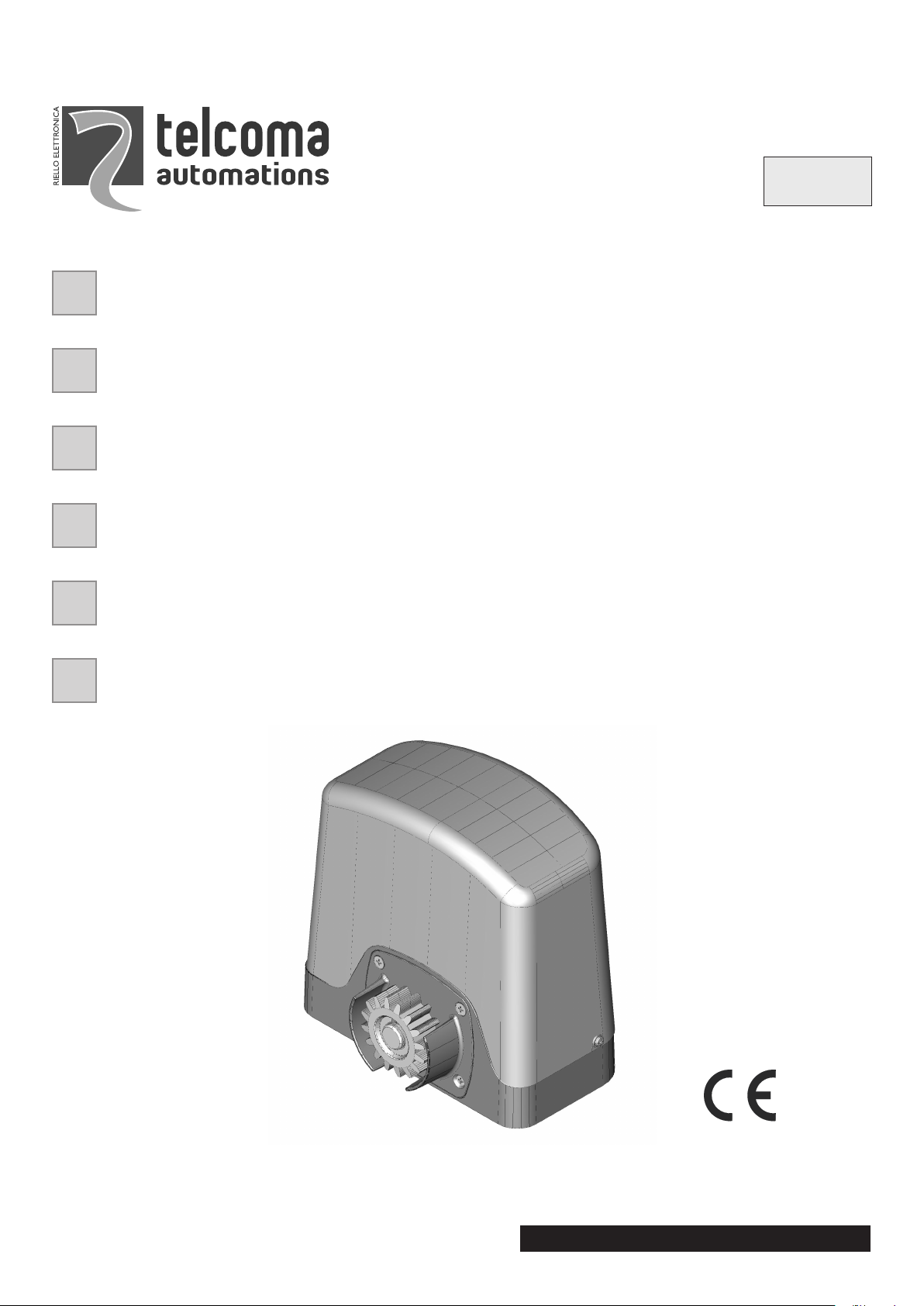
ACE 400
MOTORIDUTTORE ELETTROMECCANICO A GRASSO PER CANCELLI SCORREVOLI
MANUALE ISTRUZIONI
IL PRESENTE LIBRETTO È DESTINATO AL PERSONALE TECNICO QUALIFICATO ALLE INSTALLAZIONI
MOTO-REDUCTEURS ELECTROMECANIQUES A GRAISSE POUR PORTAILS COULISSANTS
NOTICE D'INSTRUCTION
CETTE NOTICE S'ADRESSE À DES TECHNICIENS SPÈCIALISÈS DANS L'INSTALLATION
MOTORREDUCTORES ELECTROMECÁNICOS A GRASA PARA CANCELAS CORREDIZAS
MANUAL ISTRUCCIONES
EL PRESENTE FOLLETO ESTÁ DESTINADO AL PERSONAL TECNICO ESPECIALIZADO EN INSTALACIONES
ELECTROMECHANICAL GEARMOTORS FOR SLIDING GATES
INSTRUCTION HANDBOOK
THIS HANDBOOK IS INTENDED FOR QUALIFIED TECHNICAL INSTALLERS
ELEKTROMECHANISCHER GESCHMIERTER GETRIEBEMOTOR FÜR SCHIEBETORE
BEDIENUNGANWEISUNGEN
DAS VORLIEGENDE HANDBUCH IST FÜR DAS MIT DER INSTALLATION BETRAUTE TECHNISCH QUALIFIZIERTE
FACHPERSONAL BESTIMMT
ELEKTROMECHANISCHE MOTORREDUCTOREN MET VET VOOR SCHUIFPOORTEN
GEBRUIKERSHANDLEIDING
DEZE HANDLEIDING IS BESTEMD VOOR VAKBEKWAME INSTALLATEURS
F
I
E
GB
D
NL
Telcoma srl - Via L. Manzoni, 11 - Z.I. Campidui - 31015 Conegliano - (TV) Italy
Tel. +39 0438-451099 - Fax +39 0438-451102 - Part. IVA 00809520265
http://www.telcoma.it E-mail: info@telcoma .it
ISTACE400E
E
V.09.2009
Page 2
IFE
Prima di passare all'installazione si consiglia di
effettuareleseguentiverifiche:
1. La struttura del cancello deve essere solida
edappropriata;
2.Leggere attentamente le istruzioni.
3. Accertarsi che il cancello, durantetutto il suo
movimento, non subisca punti d'attrito e che
nonvi sia pericolo di deragliamento.
4. Prevedere un fermo anta in apertura e uno in
chiusura ed il percorso dei cavi elettrici come
daimpianto tipo.
Avant de passer à l'installation, il est conseillé
d'effectuer les vérifications préliminaires
suivantes:
1. La structure du portail doit être solide et
appropriéè;
2.Lire attentivement les instructions.
3. S'assurer que la grille n'ait pas de points de
frottement durant tout le mouvement et qu'il
n'ya pas de danger de déraillement.
4. Prévoir le passage des câbles électriques
selon les dispositifs de commande et de
sécurité.
Antes de pasar a la instalación se aconseja
realizaelos siguientes controles :
1. La estructura de al cancela debe ser sólida y
adecuada;
2.Leer atentamente las instruciones.
3. Comprobar que la cancela, durante todo su
movimiento, no presente puntos de roce yque
noexista peligro de descarrilamiento.
4. Disponer un conducto para apertura los
cables eléctricos que cumpla con la
disposicionesde mando y seguridad.
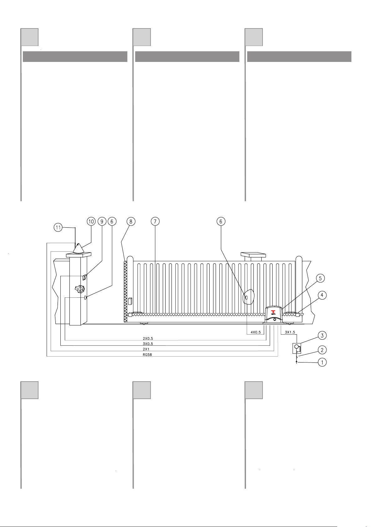
VERIFICHE PRELIMINARI VERIFICATIONS PRELIMINAIRES CONTROLES PRELIMINARES
IFE
1. Lineadialimentazione
2. Interrutoregenerale
3. Interrutoredifferenziale
4. Staffadifinecorsa
5. Ace400E
6. Fotocellula
7. Cremagliera
8. Costolasensibile
9. Selettoreachiaveotastieradigitale
10. Lampeggiatore
11. Antenna
1. Ligned'alimentation
2. Interrupteurgénéral
3. Interrupteurdifférentiel
4. Etrierdefindecourse
5. Ace400E
6. Photocellule
7. Crémaillère
8. Tranche de sécurité
9. Sélécteuràcléetclasvierdigital
10. Clignotant
11. Antenne
1. Líneadealimentación
2. Interruptorgeneral
3. Interruptordiferencial
4. Aletasdetope
5. Ace400E
6. Fotocélula
7. Cremallera
8. Nerviosensibile
9. Selectordellaveotecladodigital
10. Intermitente
11. Antena
QUADRO D'INSIEME TABLEAU D'ENSEMBLE CUADRO DE CONJUNTO
2
Page 3

GB D NL
Before installing, the followingchecks should be
carriedout:
1. The structure of the gate should be solid and
suitable;
2.Read the instructions carefully.
3. Ensure that there is no point of triction during
the gate and that there is no danger of
derailment.
4. The wiring must be routed as specified by the
controland safety requirements.
Vor de Installation ist es empfehlenswert, die
folgendenÜbertprüfungen durchzuführen:
1. Die Struktur des Tors muß solide und
geeignetsein;
2. Lesen Sie die Anleitungen aufmerksam
durch.
3. Sicherstellen, daß das Tor während der
gesamten Bewegung auf keine Reibpunktr
trifftundkeineEntgleisungsgefahrbesteht.
4. Bringen Sie einen Torstopper in
Öffnungsrichtung des Torflügels und nicht in
Schließrichtung an. Verlegen Sie die
Stromkabelso wie imAnlagenbeispiel.
Het is verstandig om vóór de installatie de
volgentecontroles te verrichten:
1. Het frame van de poort moet stevig en
geschiktzijn.
2.Lees de aanwijzingen aandachtig.
3. Controleer of er tijdens de hele beweging van
de poort geen wrijvingspunten zijn en of er
geengevaar van ontsporing is.
4. Breng een vleugelstop tijdens de opening en
een vleugelstop tijdens de sluiting aan en leg
de elektrische kabels aan zoals vermeld bijde
standaardinstallatie.
PRELIMINARY CHECKS VORBEREITENDE ÜBERPRÜFUNGEN CONTROLES VOORAF
GB D NL
1. Powersupplyline
2. On/Offswitch
3. Differentialswitch
4. Stopclamp
5. Ace400E
6. Photocell
7. Rack
8. Sensitiverib
9. Keyselectorordigitalkeypad
10. Flashinglight
11. Antenna
1. Zufuhrleitung
2. Hauptschalter
3. Differentialschalter
4. Endschalterbügel
5. Ace400E
6. Photozelle
7. Zahnstange
8. Kontaktschwelle
9. Wahlschalter mit Sclüssel oder Tastfeld
10. Blinklicht
11. Antenne
1. Voedingslijn
2. Hoofschakelaar
3. Aardlekschakelaar
4. Aanslagbeugel
5. Ace 00E
6. Fotocel
7. Tandheugel
8. Contactdrempel
9. Sleutelschakelaarofdigitaaltoetsenbord
10. Knipperlicht
11. Antenne
GENERAL VIEW GESAMTANSICHT TOTAALBEELD
3
4
Page 4
IFE
ACE400E
Motoriduttore elettromeccanico irreversibile per
cancellidal peso max di 400 Kg.
Alimentazione monofase a 230 Vac, motore 24
Vdc.
Encoder.
Pignonea cremagliera verticale M4.
Completo di piastra di fissaggio e viti di
fissaggio.
ACE400E
Motoréducteur électromécanique irréversible
pourportails d'un poids max. de 400 Kg.
Alimentation monophasée à 230 Vac,
.
Encoder.
Pignonà crémaillère verticale M4.
Dotéde plaque et vis de fixation.
moteur à
24Vdc
ACE400E
Motorreductor electromecánico para cancelas
depeso máx de 00Kg.
Alimentación monofásica a 230 Vac,
.
Encoder.
Piñóny cremallera vertical M4.
Se entrega con plancha para la fijación y
tornillosde fijación.
motor a 24
Vc.c.
MODELLI E CARATTERISTICHE MODÈLES ET CARACTÉRISTIQUES MODELOS Y CARACTERÍSTICAS
Alimentazione di rete
Alimentazione motore
Corrente max assorbita (230Vac)
Potenza max assorbita
Grado di protezione
Coppia nominale
Forza di spinta
Velocità cancello
Temperatura di funzionamento
Intermittenza lavoro
Peso
DATI TECNICI DONNÉES TECHNIQUES DATOS TÉCNICOS U.M. Ace 400E
GB D NL
Irreversible electromechanical gearmotor for
gateswith max. weight of 400 Kg.
Single-phase power supply of 230 Vac, m
.
VerticalrackandpinionM4.
Completewith fixing plate and fixing screws.
otor
powersupply 24Vdc
Elektromechanischer nicht umkehrbarer
Getriebemotor für Tore mit einem Gewicht von
max.400 Kg.
Einphasen-Versorgung230Vac, .
Ritzelemit vertkaler Zahnstange M4.
Komplett mit Befestigungsplatte und
Befestigungsschrauben.
Motors24Vdc
Onomkeerbare elektromechanische
motorreductor (met blokkering) voor poorten
meteen max. gewicht van 400 kg
Éénfasevoeding van 230 Vac,
Rondselmet verticale tandheugel M4
Inclusief bevestigingsplaat en
bevestigingsschroeven.
Motorvoeding van
24Vdc.
MODELS AND CHARACTERISTICS MODELLE UND EIGENSCHAFTEN MODELLEN EN SPECIFICATIES
TECHNICAL DATA TECHISCHE DATEN U.M. Ace 400ETECHNISCHE GEGEVENS
4
230
24
1
120
44
-20
+50
60
Alimentation secteur
Alimentation moteur
Courant max absorbé (230Vac)
Puissance max absorbée
Degré de protection
Couple nominal
Force de poussée
Vitesse portail
Température de fonctionnement
Intermittence de fonctionnement
Poids
Alimentación de red
Alimentación motor
Corriente máx. absorbida (230Vac)
Potencia máx. absorbida
Grado de protección
Par nominal
Fuerza de empuje
Velocidad de la cancela
Temperatura de funcionamiento
Intermitencia de funcionamiento
Peso
Vca
Vdc
A
W
IP
Nm
N
°C Min
Max
%
Kg
Mains power supply
otor power supply
Max current consumption (230Vac)
Max absorbed power
Protection rating
Nominal torque
Thrust force
Gate speed
Operating temperature
Duty cycle
Weight
230
24
1
120
44
-20
+50
60
Netzstromversorgung
Motorversorgung
Max. Stromaufnahme (230Vac)
Max. Leistungsaufnahme
Schutzart
Nenndrehmoment
Schubkraft
Torgeschwindigkeit
Betriebstemperatur
Intermittierender Betrieb
Gewicht
Stroomvoorziening van het elektriciteitsnet
Stroomvoorziening motor
Max. opname stroom (230Vac)
Max. opname vermogen
Beveiligingsklasse
Nominale koppel
Duwkracht
Snelheid poort
Bedrijfstemperatuur
Intermitterend bedrijf
Gewicht
Vca
Vdc
A
W
IP
Nm
N
°C Min
Max
%
Kg
ACE400E ACE400E ACE400E
Encoder. Encoder.
Encoder.
15
15
m/min
m/min
10.8
10.8
4
8
8
400
400
Page 5
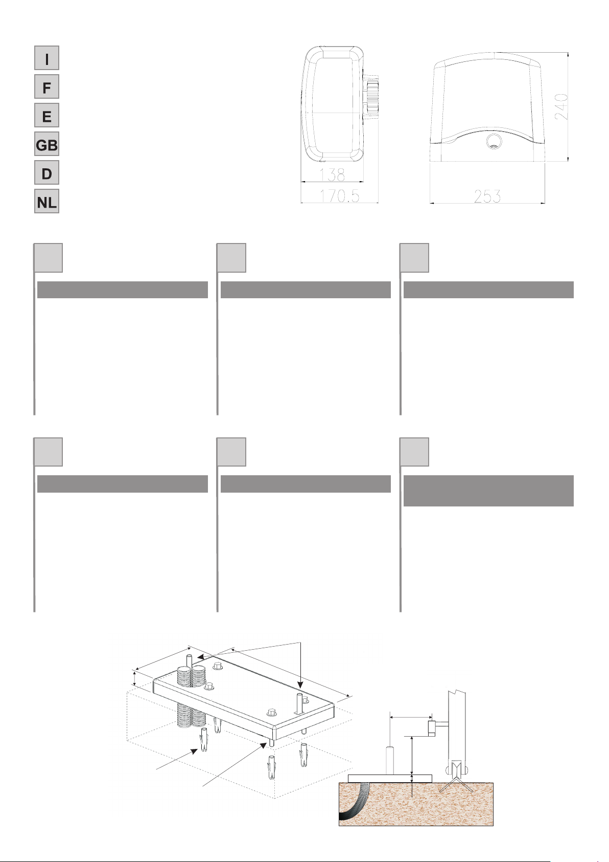
MISURE D'INGOMBRO
MEASURES
D'ENCOMBREMENT
MEDIDAS MAXIMAS EXTERNAS
OVERALL MEASUREMENTS
AUSSENABMESSUNGEN
MAATSCHETS
IFE
Rispettando le misure d'ingombro, fissare a
terra la piastra di base madiante 4 robusti
tasselli ad espansione (Fig.1 e Fig. 2) oppure
annegarlanel calcestruzzo.
Prevedere una o più guaine per il passaggio dei
cavielettrici (Fig.1)
Prima di fissare la piastra sul
cemento, inserire le viti A per poter fissare il
motoriduttoresuccessivamente.
Importante!
En respectant les dimension d'encombrement ,
fixer au sol la plaque de base à l'aide de 4 vis à
expansion ou bien noyer dans le
cimentla contre-plaque.
Prévoir une ou plusieurs gaines pourle passage
descâbles électriques (Fig.1)
Avant de fixer la plaque sur le
ciment, introduire les vis A pour pouvoir fixer le
motoréducteurpar la suite.
(Fig.1 e Fig. 2)
Important!
Respetando las medidas externas , fijar al suelo
la placa de base mediante 4 resistentes tacos
de expansión , o bien introducir
enhormigón la contraplaca.
Preparar una o variasvainas para el paso delos
cableseléctricos (Fig.1)
Antes de fijar la placa sobre el
cemento, introduzca los tornillos A para poder
fijar,después,elmotorreductor.
(Fig.1 e Fig. 2)
¡Importante!
FISSAGGIO PIASTRA DI BASE FIXATION PLAQUE DE BASE FIJACIÓN DE LA PLACA DE BASE
GB D NL
Observing the overall dimensions , fix the base
plate to the ground by means of 4 strong rawl
plugs or bury the counterplate in
theconcrete.
Plan for one more sheating for the passage of
thepower lines (Fig.1)
Introduce screws A before fixing
the plate to the concrete in order for the
gearmotorto be fixed afterwards.
(Fig.1 e Fig. 2)
Please note:
Die Grundplatte unter Beachtung der
Abmessungen mit vier soliden
Expansionsdübeln am Boden befestigen (Abb.1
-Abb.2)andemdiemitgeliefertePlattebefestigt
wird,in den Beton eingießen.
Ein oder mehrere Kabelrohre für die
Elektrokabelverlegen (Abb.1)
die Schrauben A vor der Befestigung
der Platte auf dem Beton einfügen, damit der
Getriebemotordanach befestigt werden kann.
Wichtig:
Houd de totale afmetingen aan en bevestig de
onderplaat met 4 stevige spreidpluggen
opde grond of stort de plaat in het beton.
Breng één of meer kabeldoorvoeren voor de
elektrischekabels aan (Fig. 1).
Voordat u de plaat op het beton
gaat bevestigen dient u de schroeven A aam te
nremgem om later de reductiemotor te kunnen
bevestigen.
(Fig.1 e
Fig.2)
Belangrijk!
FITTING THE BASE PLATE
BEFESTIGUNG DER GRUNDPLATTE
TECHNISCHE GEGEVENS
BEVESTIGING VAN DE
5
149
255
10
Fig.1/Abb.1
A
C
B
LATO CREMAGLIERA
85
10
86
Fig.2/ Abb. 2
Page 6
FUNZIONAMENTO MANUALE
FONCTIONNEMENT MANUEL
FUNCIONAMIENTO MANUAL
MANUAL OPERATION
MANUELLER BETRIEB
HANDMATIGE BEDIENING
F
I
E
GB
D
NL
I FE
GB D NL
6
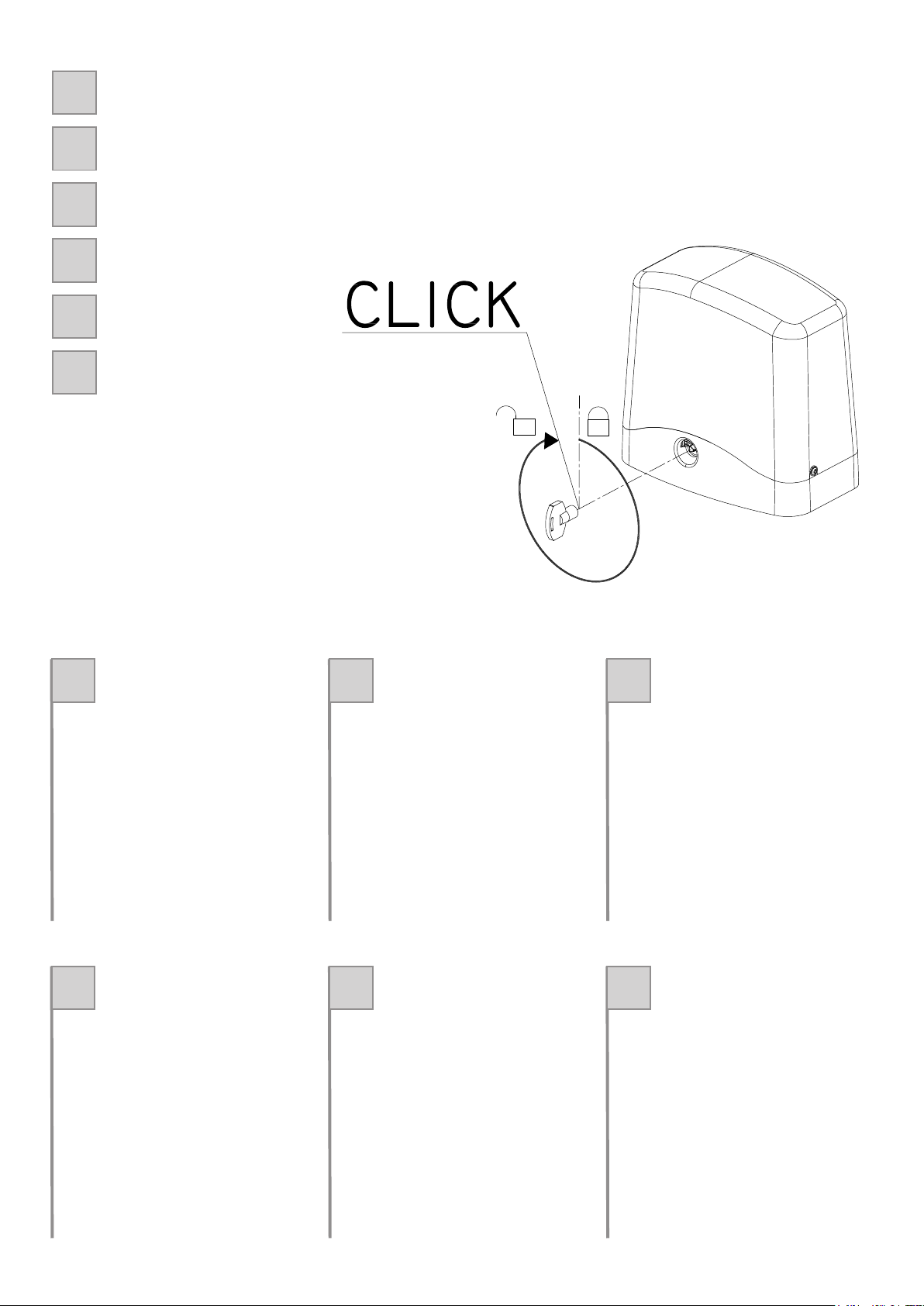
Per sbloccare il motoriduttore alzare lo
sportellino (g.3), inserire la chiave e girare
completamente in senso orario sino a quando
si avverte uno scatto. In questo momento il
cancello è svincolato e si muove liberamente.
Per bloccare il motoriduttore girare la chiave
completamente il senso antiorario sino a
quando questa si blocca.
Muovere lentamente a mano il cancello sino a
quando si avverte uno scatto negli ingranaggi.
Fig. 3/Abb. 3
Pour débrayer l’opérateur, soulever le couvercle
(g.3), introduire la clé et tourner à fond dans
le sens horaire jusqu’au déclic. À partir de ce
moment le portail est libéré et peut bouger
librement.
Pour rembrayer l’opérateur tourner la clé à
fond dans le sens horaire jusqu’à ce qu’elle se
bloque.
Bouger lentement le portail à la main jusqu’à ce
qu’en entende un déclic dans les engrenages.
Para desbloquear el motorreductor levante
la tapa (g.3), introduzca la llave y gire
completamente en sentido horario, hasta
que oiga un chasquido. En dicho momento
la cancela está desbloqueada y se mueve
libremente.
Para bloquear el motorreductor gire la llave
completamente en sentido antihorario hasta
que la misma se bloquee.
Mueva lentamente la cancela a mano hasta
que advierta un chasquido en los engranajes.
To release the gearmotor, raise the panel (g.3),
insert the key and turn it completely clockwise
until a click is heard. This detaches the gate to
enable free movement.
To lock the gearmotor, turn the key completely
anti-clockwise until it locks in place.
Slowly move the gate until you hear the gear
click and engage.
Um den Antrieb zu entriegeln, die
Luke anheben (Abb. 3), den Schlüssel
einstecken und einmal ganz im
Uhrzeigersinn umdrehen, bis ein
Einrasten zu spüren ist. Jetzt ist das Tor
freigegeben und kann sich frei bewegen.
Um den Antrieb wieder zu verriegeln,
den Schlüssel einmal ganz gegen den
Uhrzeigersinn drehen, bis er blockiert. Das
Tor langsam von Hand bewegen, bis das
Einrasten der Zahnräder zu spüren ist.
Voor het ontgrendelen van de reductiemotor
dient u het lipje (afb. 3) omhoog te halen, de
sleutel erin te steken en hem helemaal met
de wijzers van de klok mee te draaien totdat u
hem voelt klikken. Op dat moment is de poort
ontgrendeld en kan hij vrijelijk bewegen.
Voor vergrendeling dient u de sleutel helemaal
tegen de wijzers van de klok in te draaien totdat
deze niet verder kan.
Beweeg met uw hand langzaam de poort totdat
u een klik in het tandwerk voelt.
Page 7

IFE
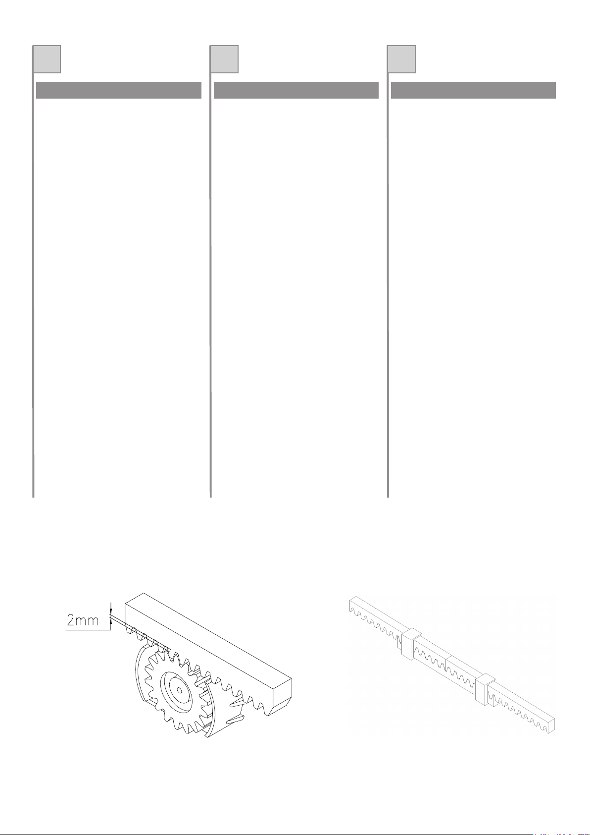
Togliere il coperchio svitando le viti (fig.4).
Appoggiare il motoriduttore sulla piastra,
avvitarei dadi alle due vitiA(fig. 5).
Prima di avvitare a fondo i 2 dadi, è possibile
regolare la distanza del motore dalla
cremaglieraagendo sulle viti indicate in fig. 6.
In seguito è importante bloccare energicamente
i due dadi M12 (fig. 5), assicurandosi che
durante tutta la corsa del cancello, il
motoriduttoresia ben saldo a terra.
Enleverle couvercle en dévissant les vis (fig.4).
Poser le motoréducteur sur la plaque, visser les
écrousaux deux vis
Avant de visser à fond les 2 écrous, on peut
régler la distance du moteur de la crémaillère à
l'aidedes vis indiquées sur la fig.6.
Ensuite, il est important de bloquer
énergiquement les deux écrous M12 (fig. 5), en
s'assurant que durant toute la course du portail,
lemotoréducteur soit solidement fixé au sol.
A(fig.5).
Quitar la tapa destornillando los dos tornillos
(fig.4)
Apoye el motorreductor sobre la placa,
enrosque las tuercas en los dos tornillos
Antes de enroscar hasta el fondo las 2 tuercas,
es posible regular la distancia entre el motor y la
cremallera, utilizando los tornillos indicados en
lafig. 6.
Luego, es importante bloquear bien fuerte las
dos tuercas M12 (fig. 5), controlando que el
motorreductor quede bien fijado al piso durante
todala carrera de la cancela.
A (fig.
5).
FISSAGGIO MOTORIDUTTORE FIXATION MOTORÉDUCTEUR FIJACIÓN DEL MOTORREDUCTOR
GB D NL
Removethe cover unscrewing the screws (fig.4)
Position the gearmotor on the baseplate and
tightenthe nuts on the two screws
Before tightening the two nuts fully down you
can adjust the distance of the motor from the
rack,by means of the screws shown in Fig. 6.
Now tighten the two M12 nuts fullydown(Fig. 5),
making sure that the gearmotor is firmly
anchored to the ground throughout the range of
gatetravel.
A(fig.5).
Die Schrauben lösen und den Deckel
abnehmen(abb.4).
Den Getriebemotor auf die Platte legen; die
Muttern auf den beiden Schrauben anbringen
Bevor die beiden Muttern fest angezogen
werden, kann die Entfernung des Motors von
der Zahnstange durch Betätigung der in Abb. 6
gezeigtenSchrauben reguliert werden.
Danach müssen die beiden M12 Muttern (Abb.
5) fest angezogen werden, so dass der
Getriebemotor während des gesamten Torlaufs
gutmit dem Boden verankert bleibt.
A
(Abb.5).
Haal de kap eraf door de schroeven eruit te
draaien(fig. 4).
Laat de reductiemotor op de plaat rusten, draai
demoeren op de twee schroeven vast
Voordat u de 2 moeren helemaal vast draait, is
het mogelijk de afstand van de motor tot de
tandheugel af te stellen; u doet dit met behulp
vande schroeven die op afb. 6 zijn aangegeven.
Vervolgensdientu - en dit is belangrijk -detwee
moeren M12 (afb. 5) stevig aan te draaien,
waarbij u zichervan dient te vergewissen dat de
reductiemotor over de gehele loop van de poort
stevigop de grond blijft.
A(fig.5).
FITTING THE GEARMOTOR BEFESTIGUNG DES ANTRIEBS BEVESTIGING VAN DE
MOTORREDUCTOR
fig. 4/Abb. 4 fig. 5/Abb. 5
A
fig. 6/Abb. 6
7
Page 8

IFE
Sbloccare il motoriduttore nel modo indicato in
Fig.3 e portare il cancello in completa apertura.
Appoggiare un elemento di cremagliera al
pignone e fissare lo stesso con viti e distanziali
alcancello.
Spostare manualmente il cancello portando il
pignone in corrispondenza dell'ultimo
distanziale. Fissare l'elemento di cremagliera
definitivamente.
Per un corretto posizionamento degli altri
elementi e garantire la loro rettilineità, è
necessario utilizzare un elemento di
cremagliera usandolo come appoggio e
referimento(fig.10).
Si deve garantire un'aria fra cremagliera e
pignone di 2 mm, così da non far gravare il peso
del cancello sul pignone del motoriduttore
(fig.9).
Nel caso di cancelli nuovi verificare in tempi
successivi all'installazione il gioco fra
cremagliera e pignone, se necessario agire
sulle asole della cremagliera per registrare i
giochi.
N.B.
Débloquer le motoréducteur (voir “Fonctionnement manuel”) ou placer en position d'ouverture
totale.
Appuyer un élément de crémaillère au pignonet
le fixer au portail à la l'aide de vis et
d'entretoises.
Déplacer manuallement le portail afin de faire
correspondre le pignon et la dernière
entretoises.
Fixerdéfinitivement l'élément de crémaillère.
Il est nècessaire d'utiliser un élément de
crémaillère comme appui et point de référence
afin de pouvoir positionner correctement les
autres éléments et de garantir leur alignement
(fig.10).
Assurer toujours un jeu d'1 mm entre la
crémaillère et le pignon de façon à ce que le
poids du portail ne repose pas sur le pignon du
motoréducteur.(fig.9).
Si le portail est neuf, contrôler, quelque temps
après l'installation, le jeu entre pignon et
crémaillère ; si une modification du jeu est
nècessaireagir sur les fentes de la crémaillère.
N.B.
Desbloquear el motorreductor (ver
“Funcionamiento manual”) o llevar la cancela a
lacompleta apertura.
Apoyar un elemento de cremallera al piñón y
fijarlocon tornillos y distanciadores a la cancela.
Desplazar manualmente la cancela hasta llevar
elpiñón a la altura de último distanciador.
Fijar definitivamente el elemento de cremallera.
Para un posicionamiento correcto de los otros
elementos de cremallera y para garantizar su
rectinilidad, es necesario utilizar un elemento de
cremalleracomo apoyo y referencia (fig.10).
Controlar que entre cremalleray piñón exista un
espacio de 1 mm para que elpeso de la cancela
no caiga sobre el piñón del motorreductor
(fig.9).
En el caso de cancelas nuevas, controlar,
después de la instalación, el juego entre
cremallera u piñón ; si es necesario registrar el
juego « cremallera/piñón” por medio de las
ranurasde la cremallera.
Nota:
MONTAGGIO CREMAGLIERA MONTAGE CREMAILLERE MONTAJE CREMALLERA
Fig. 10/Abb. 10Fig. 9/Abb. 9
8
Page 9
GB D NL
Release the gearmotor (see “Manual
operation”)or fully open the gate.
Rest a rack elementon the pinion and fixit to the
gateusing screws and spacers.
Move the gate manually until the pinion is in line
withthe last spacer.
Move the gate manually intil the pinion is in line
withthe last spacer.
Permanentlyfix the rack element.
A rack element must be used as resting and
reference point in order to position the other rack
elements correctly and make sure they are in a
straightline (fig.10).
Make sure that there is a spaceof1mm between
the rack and the pinion so that the weight of the
gate does not rest on the gearmotor pinion
(fig.9).
With new gates, check the backlash or play
between rack and pinion at intervals following
installation and if necessary adjust by means of
theslots in the rack.
N.B.
Den Getriebemotor deblockieren (siehe
“Manueller Betrieb”) und das Tor vollständig
öffnen.
Ein Element der Zahnstange an den Kolben
anlegen und mit Schraauben und
AbstandsstückenamTor befestigen.
Das Tor manuell versetzen, bis daß der Kolben
in Übereinstimmung mit dem letzten
Abstandsstückgebracht ist.
Das Element der Zahnstange definitiv
befestigen.
Für eine einwandfreie Plazierung der anderen
Zahnstangenelemente und um deren
geradlinigeAusrichtung zu gewährleisten, ist es
notwendig, ein Zahnstangenelement als
Auflageund Referenz zu verwenden (abb.10).
Sicherstellen, daß zwischen Zahnstange und
Kolben ein Zwischenraum von1 mm besteht, so
daß das Gewicht des Tors den Kolben des
Getriebemotorsnicht belastet (abb.9).
Bei neuen Toren in der Zeit nach der Installation
das Spiel zwischen Zahnstange und Kolben
überprüfen; falls notwendig die Löcher der
Zahnstange betätigen, um das Spiel
„Zahnstange/Kolben“einzustellen.
Hinweis:
Ontgrendel de motorreductieaandrijving (zie
“handbediende werking”) of zet het hek
helemaalopen.
Leg een element van de tandheugel op het
tandwiel en maak dit element met schroeven en
afstandshoudersaan het hek vast.
Verplaats het hek met de hand totdat het
tandwiel zich ter hoogte van de laatste
afstandshouderbevindt.
Maakhet tandheugelelement definitief vast.
Om ervoor te zorgen dat de andere elementen
van de tandheugel op de juiste plaats komen te
zitten en om er zeker van te zijn dat de
elementen recht zitten moet u één
tandheugelelement als steun en als
uitgangspuntnehmen (fig.10).
Controleer of er tussen de tandheugel en het
tandwiel 1 mm speling zit zodat het gewicht van
het hek geen belasting voor de
motorreductieaandrijvingvormt (fig.9).
Bij nieuwe hekken moet u na de installatie de
speling tussen de tandheugel en het tandwiel
regelmatig controleren ; indien nodig moet u de
speling tussen de tandheugel en het tandwiel
met behulp van gleuven van de tandheugel
afstellen.
N.B.
RACK ASSEMBLY MONTAGE DER- ZAHNSTANGE DE TANDHEUGEL MONTEREN
9
Fig. 10/Abb. 10Fig. 9/Abb. 9
Page 10

IFE
Gli ACE400E montano un finecorsa elettronico
non visibile dall'esterno indicato in figura 7 con
lalettera S.
Posizionare le staffe con i magneti M e fare
attenzione a che ciascuna staffa sia
sufficientemente vicina al finecorsa elettronico
S in modo da garantire lo stop del motore. La
distanza da tenere tra magneteMeilfinecorsa
S deve essere compresa frai2edi8mm
massimo.
Portare manualmente il cancello in apertura,
evitando che vada in battuta contro il fermo
meccanico, fissare quindi la staffa del finecorsa
mediante i grani (fig./Abb8) in modo che ilpunto
(M) in Fig./Abb.7 sia al centro del pignone (S).
Fare riferimento anche alle istruzioni della
centralinaelettronica
Les ACE400E ont un fin de course électronique
non visible de l'extérieur indiqué sur la figure 7
parla lettre S.
Placer les étriers avec les aimants M et faire
attention à ce que chaque étrier soit
suffisamment proche du fin de course
électronique S de manière à garantir l'arrêt du
moteur.La distance à garder entre l'aimant M et
le fin de course S doit être comprise entre 2 et 8
mmmaximum.
Amener manuellement le portail en ouverture,
en évitant qu'ilne bute contrel'arrêt mécanique,
fixer ensuite l'étrier du fin de course à l'aide des
goujons (fig./Abb 8) de façon à ce que le point
(M) sur la Fig./Abb.7 soit au centre du pignon
(S). Se reporter aussi aux instructions de la
centraleélectronique.
Los ACE400E montan un fin de carrera
electrónico no visible desde afuera, indicado
conla letra S en la figura 7.
Coloque las placas con imanes M y compruebe
que cada placa esté suficientemente cerca del
fin de carrera electrónico S para garantizar la
parada del motor. La distancia entre los imanes
M y el fin de carrera S debe estar comprendida
entre2y8mmcomo máximo.
Abra manualmente la cancela sin que toque el
topemecánico, fije la placa del fin de carrera con
los tornillos sin cabeza (fig./Abb 8), de manera
que el punto (M) de la Fig./Abb.7 quede en el
centro del piñón (S). Consulte también las
instruccionesde la central electrónica.
FISSAGGIO FINECORSA
FIXATION BUTTÉES FINS DE COURSE
FIJACIÓN DE LA ALETAS DE TOPE
GB D NL
ACE400E units are equipped with an electronic
limit switch indicated by letter S in figure 7 (the
limitswitch is not visible from the outside).
Position the brackets with magnets (M) and
make sure that each bracketis sufficiently close
to the electronic limit switch (S) to as to ensure
the motor is stopped. There must be a gap of
between 2 and 8 mm between magnet (M) and
limitswitch (S).
Manually open the gate without it touching the
mechanical stop, and then fix the limit switch
bracket using the grub screws (Fig./Abb. 8) so
that point (M) in Fig./Abb. 7 is at the centre of
pinion (S). Refer also to the instructions for the
electroniccontrol unit.
Die Torantriebe ACE400E verfügen über einen
von außen nicht sichtbaren, elektronischen
Endschalter, der in Abbildung 7 mit dem
BuchstabenS angegeben ist.
Die Bügel mit den Magneten M anbringen und
darauf achten, dass sich jeder Bügel genügend
nah am elektronischen Endschalter S befindet,
so dass das Anhalten des Motors gewährleistet
ist. Die Entfernung zwischen Magnet M und
Endschalter S muss zwischen max. 2 und 8 mm
sein.
Das Tor von Hand so weit öffnen, dass es den
mechanischen Endanschlag nicht erreicht,
dann den Endschalterbügel mit den
Stiftschrauben (Abb. 8) so befestigen, dass sich
der Punkt (M) in Abb. 7 in der Mitte des Ritzels
(S) befindet. Auch auf die Anweisungen der
elektronischenSteuerung Bezug nehmen.
Op de ACE400E is een elektronische
eindschakelaar gemonteerd die van buitenaf
niet zichtbaar is; op afbeelding7 wordt deze met
deletter S aangeduid.
Plaats de beugels met de magneten M en let
erop dat elke beugel zich dicht genoeg bij de
elektronische eindschakelaar S bevindt, zodat
de motor gegarandeerd stopt. De tussen de
magneet M en de eindschakelaar S aan te
houden afstand dient tussen de 2 en ten
hoogste8 mm te liggen .
Zet de poort handmatig open en vermijd daarbij
dat die tegen de mechanische stop komt; zet
daarna de beugel van de eindschakelaar met
stifttappen zo vast (afb./Abb 8) dat het punt (M)
opAfb./Abb.7zich in het midden vanhet rondsel
(S) bevindt. Raadpleeg ook de aanwijzingen
vande elektronische besturingseenheid.
ATTACHING THE SWITCH TABS
MONTAGE DE ENDSCHALTERBÜGEL
BEVESTIGING VAN DE
EINDSCHAKELAARS
M
Max8mm
M
Fig. 7/Abb. 7
S
Fig. 8/Abb. 8
10
Page 11

IFE
Ace400E è provvisto di una sede per poter
installare due batterie tampone da 12V 1.2Ah,
che collegate opportunamente alla centralina
elettronica possono garantire, per un tempo
limitato, l'apertura ela chiusura dell'antain caso
mancassel'alimentazione di linea. (Fig./Abb.11)
Ace400E est muni d'un logement pour pouvoir
installer deux batteries tampon de 12V 1.2Ah,
qui, reliées de manière appropriée à la centrale
électronique, peuvent garantir pendant un
temps limité, l'ouverture et la fermeture du
vantail en cas de coupure d'alimentation de
ligne.(Fig./Abb.11)
Ace400E está dotado de un alojamiento para
instalar dos baterías compensadoras de 12V
1.2Ah, que, al estar conectadas a la central
electrónica, pueden garantizar, durante un
tiempo limitado, la apertura y el cierre de la
puerta si faltara la alimentación de línea
(Fig./Abb.11).
BATTERIE TAMPONE
BATTERIES TAMPON
BATERÍAS COMPENSADORAS
GB D NL
ACE400E features a housing designed to accept
two 12V 1.2A back-up batteries which, when
connected to the electronic control unit, will
provide sufficient power to open and close the
gate for a limited time in the case of a mains
powerfailure (Fig./Abb.11).
Ace400E verfügt über ein Abteil zum Einbau von
zwei 12V 1.2Ah Pufferbatterien, die wenn
korrekt mit der elektronischen Steuerung
verbunden das Öffnen und Schließen des Tors
bei Stromausfall für eine bestimmte Zeit
garantierenkönnen (Abb. 11).
Op de ACE400E is een plaats gereserveerd waar
twee bufferbatterijen van 12V 1.2Ah
gemonteerd kunnen worden. Wanneer deze op
de elektronische besturingseenheid zijn
aangesloten kunnen zij voor een bepaalde tijd
het openen en sluiten van de vleugel
garanderen, mocht de stroom van het
elektriciteitsnetuitvallen. (Afb./Abb.11)
BATTERIES WHICH
PUFFERBATTERIEN
BUFFERBATTERIJEN
11
Fig. 11/Abb.11
2X
TIPO: 12V 1,2Ah
DIM : 44x98x52mm
Cb24
Page 12

IFE
Il cancello non apre o non chiude ; il motore
elettrico non funziona e non si avverte,
quindi,alcun rumore o vibrazione :
Il cancello non apre; il motore funziona ma
nonavviene il movimento:
1. Verificare che la centralina elettronica sia
regolarmentealimentata.
2. Verificare l'efficienza dei fusibili.
3. Verificare, con l'ausilio di adeguati strumenti
diagnostici, che le funzioni
dell'apparecchiatura elettronica siano
corrette.
4. Accertarsicheilmotorericevaalimentazione.
1. Verificare che il pignone dentato sia in presa
conla cremagliera.
2. Controllare che il motoriduttore non sia
sbloccato.
Può darsi che il motoriduttore sia bloccato da
uno dei due arresti meccanici; in tal caso
bisogna sbloccare manualmente il motore,
azionare il cancello a mano, liberandolo da
quella posizione anomala e, prima di
ripristinare il funzionamento automatico,
posizionare correttamente le staffe di
finecorsa.
Le portail ne s'ouvre pas et nese ferme pas.
Le moteurnefonctionne pasetdonc aucune
rumeurnivibration ne peut être perçue
Le portail ne s'ouvre pas, le moteur
fonctionne sans que ne se produise de
mouvement.
.
1. Vérifier que la centrale électronique de
commandesoit normalement alimentée.
2. Vérifierl'étatdesfusibles.
3. Vérifier, à l'aide d'instruments de diagnostic
adéquats, que les fonctions de la centrale
électroniquesoient normales.
4. S'assurerquelemotoréducteurestalimenté.
1. Vérifierque le pignon dentésoit en prise avec
lacrémaillère.
2. Contrôlerquelemotoréducteur ne soit pas en
position« manuelle » (débloqué).
Contrôler que le motoréducteur ne soit pas
bloqué par un des deux arrêts mécaniques.
Dans ce cas-là, débloquer manuellement le
moteur et actionner le portail à la main, en le
libérant, de ce fait,de cette position anormale.
Placer correctement les étriers de fin de
course et rétablir le fonctionnement
automatique.
La cancela no se abre ni cierra, el motor no
funciona y no se advierte, por lo tanto,
ningúnruidoo vibración.
La cancela no abre. El motor funciona, pero
nose realiza el movimiento.
1. Controlar que la caja de mandos electrónica
estéregularmente alimentada.
2.Controlar la eficiencia de los fusibles.
3. Verifcar, con la ayuda de adecuados
instrumentos diagnósticos; que las funciones
de la caja de mandos electrónica sean
correctas.
4. Asegurarse que el motorreductor reciba
alimentación.
1. Controlar que el piñón dentado engrane con
lacremallera.
2. Controlar que el motorreductor no esté en
posición“manual” (desbloqueado).
Controlar que el motorreductor no esté
bloqueado por uno de los dos paros
mecánicos. En tal caso desbloquear
manualmente el motor y accionar la cancelaa
mano soltándola, de este modo, de esta
situación anómala. Posicionar, luego,
correctamente las abrazaderas de los topes
de recorrido y restablecer el funcionamiento
automático.
ANOMALIE DI FUNZIONAMENTO.
RIMEDI
ANOMALIES DE
FONCTIONNEMENT.
REMEDES
ANOMALIAS DE
FUNCIONAMIENTO.
REMEDIOS
12
Page 13

GB D NL
The gate neither opens nor closes. The
motor does not work and there is
consequentlyno noise or vibration.
The gate does not open. The motor works
butthere is no movement.
1. Check that the electronic control unit is
regularlypowered.
2. Checkthefuses.
3. Using suitable diagnostic instruments, check
that the electronic unit is in proper working
order.
4. Makesurethatthegearmotorispowered.
1. Check that the toothed pinion is in mesh with
therack.
2. Check that the gearmotor is not in the
“manual”position (released).
Check that the gearmotor is not locked in
place by one or more mechanical stops.If it is,
releasethe motor manually and move the gate
by hand to free it. Finallycorrectthe position of
the stop clamps and reset automatic
operation.
DasToröffnetundschließtsichnicht.
Der Motorfunktioniert nicht und es ist daher
keinerlei Geräusch oder Vibration
wahrnehmbar.
Das Tor öffnet sich nicht. Der Motor
funktioniert, es erfolgt jedoch keinerlei
Bewegung.
1. Überprüfen, daß die elektronische
Steuereinheit ordnungsgemäß unter
Spannungsteht.
2. Die Leistungsfähigkeit der Sicherungen
überprüfen.
3.Mit Hilfe der entsprechenden
Diagnoseinstrumente überprüfen, daß die
Funktionen der elektronischen Steuereinheit
einwandfreisind.
4. Sicherstellen, daß der Getriebemotor unter
Spannungsteht.
1. Überfrüfen, daß der gezahnte Kolben in die
Zahnstangegreift.
2. Kontrollieren, daß sich der Getriebemotor in
der “manuellen“ Stellung (deblockiert)
befindet.
Kontrollieren, daß der Getriebemotor nicht
von einer der beiden mechanischen
Verriegelungen blockiert ist. In diesem Fall
den Motor manuell deblokieren und das Tor
per Hand betätigen und aus dieser anomalen
Position befreien. Danach die Bügel der
Endschalter korrekt positionieren und den
Automatikbetriebwiederherstellen.
Het hak gaat open en niet dicht. De motor
functioneert niet en u neemt dan ook geen
enkelgeluid of trilling waar.
Het hek gaat niet open. Den motor
functioneert, maar er vindt ondanks dat
gennbeweging plaats.
1. Controleer of de elektronische
besturingseenheid op correcte wijze stroom
toegevoerdkrijgt.
2. Controleerofdezekeringenefficiëntzijn.
3. Controleer met behulp van geschikte
diagnose-apparatuur of de elektronische
besturingseenheidgoed functioneert.
4. Controleer of de motorreductieaandrijving
stroomtoegevoerd krijgt.
1. Controleer of het tandwiel goed in de
tandheugelingrijpt.
2. Ga na de motorreductieaandrijving niet op de
“handbedieningsstand”staat (ontgrendeld is).
Ga na dat de motorreductieaandrijving niet
geblokkeerd is door één van de mechanische
aanslagen. In dat geval moet u de motor met
de hand deblokkeren en het hek met de hand
in werking stellen en uit deze abnormalestand
bevrijden. Zet de beugels van de aanslagen
daarna in de goede stand en herstel de
automatischewerking.
OPERATING PROBLEMS.
REMEDIES
BETRIBSSTÖRUNGEN.
BEHEBUNG
STORINGEN EN OPLOSSINGEN
13
Page 14

ISTRUZIONI IMPORTANTI DI SICUREZZA.
E’ importante per la sicurezza delle persone leggere
attentamente queste istruzioni.
1. L’installazione dell’automazione deve essere
eseguita a regola d’arte da personale qualicato
avente i requisiti di legge e fatta in conformità
della direttiva macchine 98/37/CE e alle normative
EN13241-1, EN 12453 e EN 12445.
2. Vericare la solidità delle strutture esistenti
(colonne, cerniere, ante) in relazione alle forze
sviluppate dal motore.
3. Vericare che vi siano dei fermi meccanici di
adeguata robustezza a ne apertura e ne chiusura
delle ante.
4. Vericare lo stato di eventuali cavi già presenti
nell’impianto.
5. Fare un’analisi dei rischi dell’automazione e di
conseguenza adottare le sicurezze e le segnalazioni
necessarie.
6. Installare i comandi (ad esempio il selettore a
chiave) in modo che l’utilizzatore non si trovi in una
zona pericolosa.
7. Terminata l’installazione provare più volte i
dispositivi di sicurezza, segnalazione e di sblocco
dell’automazione.
8. Applicare sull’automazione l’etichetta o la targhetta
CE contenenti le informazioni di pericolo e i dati di
identicazione.
9. Consegnare all’utilizzatore nale le istruzioni d’uso,
le avvertenze per la sicurezza e la dichiarazione
CE di conformità.
10. Accertarsi che l’utilizzatore abbia compreso il
corretto funzionamento automatico, manuale e di
emergenza dell’automazione.
11. Informare l’utilizzatore per iscritto (ad esempio
nelle istruzioni d’uso) :
a. dell’eventuale presenza di rischi residui non
protetti e dell’uso improprio prevedibile.
b. Di scollegare l’alimentazione quando viene
eseguita la pulizia nell’area dell’automazione
o viene fatta piccola manutenzione (es:
ridipingere).
c. Di controllare frequentemente che non vi siano
danni visibili all’automazione e nel caso ve ne
siano, avvertire immediatamente l’installatore
d. Di non permettere ai bambini di giocare con i
controlli dell’automazione.
e. Di tenere i telecomandi fuori dalla portata dei
bambini.
12. Predisporre un piano di manutenzione dell’impianto
(almeno ogni 6 mesi per le sicurezze) riportando su
di un apposito registro gli interventi eseguiti.
ATTENZIONE PERICOLO!
I F E
CONSIGNES DE SÉCURITÉ IMPORTANTES
Il est important, pour la sécurité des personnes, de lire
attentivement ces consignes.
1. L’installation de l’automation doit être effectuée dans les
règles de l’art par du personnel spécialisé, conformément
aux dispositions légales, à la directive machine 98/37/CE
et aux normes EN 12453 et EN 12445.
2. S’assurer que les structures existantes (colonnes,
charnières, vantaux) soient sufsamment solides pour
résister aux forces développées par le moteur.
3. S’assurer que les arrêts mécaniques en n d’ouverture
et en n de fermeture des vantaux soient sufsamment
robustes.
4. Vérier l’état des câbles qui se trouvent éventuellement
déjà dans l’installation
5. Faire une analyse des risques de l’automation et adopter,
en fonction de celle-ci, les dispositifs de sécurité et de
signalisation nécessaires.
6. Installer les commandes (par exemple le sélecteur à clé)
de manière à ce que l’utilisateur ne se trouve pas dans
une zone dangereuse.
7. Une fois l’installation terminée, tester plusieurs fois les
dispositifs de sécurité, de signalisation et de déverrouillage
de l’automation.
8. Appliquer sur l’automation l’étiquette ou la plaque CE
où sont indiqués les dangers présentés par l’automation
ainsi que les données d’identication de la machine.
9. Remettre à l’utilisateur nal le mode d’emploi, les
avertissements concernant la sécurité et la déclaration
CE de conformité.
10. S’assurer que l’utilisateur a bien compris le fonctionnement
automatique, manuel et d’urgence de l’automation.
11. Informer l’utilisateur par écrit (par exemple dans le mode
d’emploi) :
a. de la présence éventuelle de risques résiduels non
protégés et de l’usage impropre prévisible.
b. De la nécessité de couper l’alimentation quand le
nettoyage de la zone de l’automatisme a lieu ou en
cas de petites interventions de maintenance (ex.
repeindre).
c. De la nécessité de contrôler fréquemment l’absence de
dommages visibles à l’automatisme et s’il y en a, avertir
immédiatement l’installateur.
d. Ne pas autoriser les enfants à jouer avec les
commandes de l’automatisme;
e. Tenir les émetteurs hors de portée des enfants.
12. Etablir un plan de maintenance de l’installation (au
moins tous les 6 mois pour les dispositifs de sécurité) en
inscrivant sur un registre prévu à cet effet les interventions
effectuées.
ATTENTION: DANGER!
INSTRUCCIONES IMPORTANTES DE SEGURIDAD.
Para la seguridad de las personas es importante leer
detenidamente estas instrucciones.
1. La instalación del automatismo debe ser realizada según
los cánones, por personal cualicado que reúna los
requisitos establecidos por la ley y de conformidad con la
Directiva sobre máquinas 98/37/CE y con las normas EN
12453 y EN 12445.
2. Compruebe la solidez de las estructuras existentes
(columnas, bisagras, hojas) en relación con las fuerzas
desarrolladas por el motor.
3. Controle que haya retenes mecánicos de solidez
adecuada en los puntos de n de apertura y de n de
cierre de las hojas.
4. Controle el estado de los cables ya existentes en la
instalación, en su caso.
5. Haga un análisis de los riesgos del automatismo y
adopte los dispositivos de seguridad y las señalizaciones
necesarias en consecuencia.
6. Instale los mandos (por ejemplo, el selector de llave)
de manera que el usuario no se encuentre en una zona
peligrosa.
7. Terminada la instalación, pruebe varias veces los
dispositivos de seguridad, señalización y desbloqueo del
automatismo.
8. Aplique en el automatismo una etiqueta o una placa CE
que contenga las informaciones de peligro y los datos de
identicación.
9. Entregue al usuario nal las instrucciones para el uso,
las advertencias para la seguridad y la declaración CE de
conformidad.
10. Asegúrese de que el usuario haya comprendido el correcto
funcionamiento automático, manual y de emergencia del
automatismo.
11. Informe al usuario por escrito (por ejemplo en las
instrucciones de uso) :
a. sobre la presencia de riesgos residuales no
protegidos y sobre el uso inadecuado previsible.
b. que debe desconectar la alimentación cuando hace la
limpieza en la zona de la automatización o si hace un
pequeño mantenimiento (ej.: pintar).
c. que debe controlar a menudo que la automatización
no presente daños visibles y, en el caso de que los
haya, deberá advertir de inmediato al instalador
d. Que no permita a los niños jugar con los controles de
la automatización.
e. Que mantenga los telemandos fuera del alcance de
los niños.
12. Predisponga un programa de mantenimiento de la
instalación (al menos cada 6 meses para los dispositivos
de seguridad), anotando en un registro expresamente
dedicado las intervenciones realizadas.
¡ATENCIÓN PELIGRO!
Questo prodotto è formato da vari componenti che
potrebbero a loro volta contenere sostanze inquinanti.
Non disperdere nell’ambiente!
Informarsi sul sistema di riciclaggio o
smaltimento del prodotto attenendosi alle
norme di legge vigenti a livello locale.
SMALTIMENTO
Ce produit est constitué de divers composants qui
pourraient à leur tour contenir des substances polluantes.
Ne pas laisser ce produit gagner l’environnement.
S’informer sur le système de recyclage ou
d’élimination du produit conformément aux
dispositions légales en vigueur à un niveau local.
ELIMINATION
Este producto está constituido por varios componentes
que podrían, a su vez, contener sustancias contaminantes.
¡No los vierta en el medio ambiente!
Infórmese sobre el sistema de reciclaje o
eliminación del producto con arreglo a las
leyes vigentes en ámbito local.
ELIMINACION
14
Page 15

GB D NL
IMPORTANT SAFETY WARNINGS
For safety reasons, it is essential that all persons read
these instructions carefully.
1. Only qualied personnel having the legal
requirements must install the automation according
to the principles of good workmanship and in
conformity with the machinery directive 98/37/CE
and standards EN 12453 and EN 12445.
2. Check that the existing structures (posts, hinges,
leaves) are stable in relation to the forces developed
by the motor.
3. Check that suitably robust limit stops have been
installed for end of gate opening and closing.
4. Check the state of the cables that are already
present in the system.
5. Analyse the hazards connected with the automation
system and adopt the necessary safety and
signalling devices accordingly.
6. Install the commands (e.g. the key selector) so that
the user is not placed in a hazardous area when
using them.
7. Upon completion of the installation, test the safety,
signalling and release devices of the automation
system several times.
8. Apply the CE label or plate with information
regarding the hazards and identication data on
the automation.
9. Give the end user the instructions for use, the
safety recommendations and the CE declaration of
conformity.
10. Ensure that the user has understood the correct
automatic, manual and emergency operation of the
automation system.
11. Inform the user in writing (in the use instructions for
example):
a. Of possible non secluded residual risks and of
foreseeable improper use.
b. To disconnect the power supply when
cleaning the area that is automated or when
performing small maintenance operations (e.g.:
repainting).
c. To frequently control that no visible damage
has occurred to the automation, and to inform
the installer immediately if damage is noticed.
d. Never allow children to play with automation
controls.
e. Keep remote controls out of the reach of
children.
12. Prepare a maintenance schedule for the automation
installation (at least once every 6 months for the
safety devices), recording the work carried out in a
special book.
CAUTION! DANGER!
WICHTIGE SICHERHEITSHINWEISE
Es ist wichtig für die Sicherheit der Personen, diese Anweisungen
aufmerksam zu lesen.
1. Die Installation der Automatisierung muss in
Übereinstimmung mit der Maschinenrichtlinie 98/37/EU
und den Bestimmungen EN 12453 und EN 12445,
fachgerecht und von qualiziertem Personal, das die
gesetzlichen Anforderungen erfüllt, vorgenommen
werden.
2. Die Stabilität der vorhandenen Strukturen (Säulen,
Scharniere, Flügel) im Hinblick auf die vom Motor
entwickelten Kräfte überprüfen.
3. Sicherstellen, dass am Öffnungsanschlag und am
Schließanschlag der Torügel ausreichend robuste
mechanische Feststellvorrichtungen vorhanden sind.
4. Den Zustand eventueller, bereits in der Anlage
vorhandener Kabel überprüfen.
5. Die Risiken, die durch die Automatisierung
entstehen können, abwägen und dementsprechende
Sicherheitsvorkehrungen treffen, sowie die erforderlichen
Warnhinweise anbringen.
6. Die Steuerungen (z.B. Schlüsselschalter) so installieren,
dass sich der Benutzer nicht in einem Gefahrenbereich
aufhalten muss.
7. Nach abgeschlossener Installation mehrmals die
Sicherheits-, Anzeige- und Entsperrvorrichtungen der
Automatisierung erproben.
8. Auf der Automatisierung die EU- Etikette oder das EUSchild anbringen, auf dem die Gefahrenhinweise und die
Kenndaten aufgeführt sind.
9. Dem Endkunden die Bedienungsanweisung, die
Sicherheitshinweise und die EU-Konformitätserklärung
aushändigen.
10. Sicherstellen, dass der Bediener die korrekte automatische
und manuelle Funktionsweise sowie den Notbetrieb der
Automatisierung verstanden hat.
11. Den Benutzer schriftlich (z.B. in den
Bedienungsanleitungen) über folgendes informieren:
a. eventuelles Vorhandensein nicht geschützter
Restrisiken; vorhersehbarer unsachgemäßer
Gebrauch
b. Vorschrift, die Stromversorgung abzutrennen, wenn
im Bereich der Automatisierung gereinigt wird oder
kleine Instandhaltungen ausgeführt werden (wie z.B.
neuer Anstrich)
c. dass er die Automatisierung häug auf sichtbare
Schäden zu überprüfen und ggf. unverzüglich den
Installateur zu benachrichtigen hat
d. Kinder nicht mit den Steuervorrichtungen des
Automationssystems spielen lassen.
e. Die Fernbedienungen für Kinder unzugänglich
aufbewahren.
12. Einen Wartungsplan für die Anlage vorbereiten (die
Sicherheitsvorrichtung müssen mindestens alle 6 Monate
gewartet werden) und die ausgeführten Wartungseingriffe
in einem entsprechenden Verzeichnis anmerken.
VORSICHT GEFAHR!
BELANGRIJKE VEILIGHEIDSVOORSCHRIFTEN.
Voor de veiligheid van de betrokken personen is het belangrijk
deze voorschriften aandachtig door te lezen.
1. De installatie van de automatisering moet op deugdelijke
wijze uitgevoerd worden door vakmensen die aan de
wettelijke eisen voldoen en moet in overeenstemming
zijn met de Machinerichtlijn 98/37/EG en de normen EN
12453 en EN 12445.
2. Er moet gecontroleerd worden of de bestaande
constructie-elementen (zuilen, scharnieren, vleugels)
stevig zijn met het oog op de kracht die door de motor
ontwikkeld wordt.
3. Er moet gecontroleerd worden of er aan het einde van de
opening en aan het einde van de sluiting van de vleugels
mechanische stops zijn die stevig genoeg zijn.
4. Controleer de staat van de kabels die eventueel reeds in
de installatie aanwezig zijn.
5. Er moet een risicoanalyse van de automatisering
gemaakt worden en op basis daarvan moeten de nodige
veiligheids- en waarschuwingssystemen toegepast
worden.
6. De bedieningselementen (bijv. de sleutelschakelaar)
moeten zodanig geïnstalleerd worden dat de gebruiker
zich niet op gevaarlijke plaatsen bevindt.
7. Na aoop van de installatie moeten de veiligheids-
, waarschuwings- en ontgrendelsystemen van de
automatisering diverse keren getest worden.
8. Op de automatisering moet het CE-etiket of het CE-plaatje
met informatie over de gevaren en de typegegevens
aangebracht worden.
9. De gebruiksaanwijzing, de veiligheidsvoorschriften en
de EG-verklaring van overeenstemming moeten aan de
eindgebruiker gegeven worden.
10. Er moet nagegaan worden of de gebruiker de juiste
automatische, handbediende en noodwerking van de
automatisering begrepen heeft.
11. Informeer de gebruiker schriftelijk (bijvoorbeeld in
de aanwijzingen voor gebruik) ten aanzien van het
volgende:
a. eventueel nog aanwezige niet-beveiligde restrisico’s
en voorspelbaar oneigenlijk gebruik.
b. de stroomtoevoer los te koppelen wanneer er
schoonmaakwerkzaamheden in de zone rondom de
automatisering worden verricht of klein onderhoud
(bijvoorbeeld: schilderwerk).
c. dikwijls te controleren dat er geen zichtbare schade
aan de automatisering is, en indien die er is,
onmiddellijk de installateur te waarschuwen
d. Laat kinderen niet spelen met de bediening van het
automatische systeem.
e. Houd de afstandbedieningen buiten bereik van
kinderen.
12. Er moet een onderhoudsplan van de installatie
opgesteld worden (minimaal om de 6 maanden voor de
beveiligingen) waarbij de uitgevoerde werkzaamheden in
een speciaal register genoteerd moeten worden.
LET OP GEVAAR!
Dieses Produkt besteht aus verschiedenen Bauteilen, die
ihrerseits die Umwelt verschmutzende Stoffe enthalten
können. Sachgerecht entsorgen!
Informieren Sie sich, nach welchem
Recycling- oder Entsorgungssystem das
Produkt entsprechend der örtlich geltenden
Bestimmungen zu entsorgen ist.
Dit product bestaat uit diverse onderdelen die ook weer
verontreinigende stoffen kunnen bevatten. Het product
mag niet zomaar weggegooid worden!
Informeer over de wijze van hergebruik
of verwijdering van het product en neem
daarbij de wettelijke voorschriften die ter
plaatse gelden in acht.
This product is made up of various components that
could contain pollutants. Dispose of properly!
Make enquiries concerning the recycling or disposal
of the product, complying with the local
laws in force.
DISPOSAL ENTSORGUNG VERWIJDERING
15
Page 16

16
Page 17

NOTE
Page 18

NOTE
Page 19
AUTOMATISMI PROFESSIONALI PER CANCELLI E GARAGE
PROFESSIONAL GARAGE DOOR AND GATE OPERATORS
DICHIARAZIONE CE
MOTORIDUTTORE
“ ”
Il fabbricante:
Telcoma srl
Via L. Manzoni, 11
31015 - Z.I. Campidui - Conegliano (TV)
ITALY
DICHIARA che il prodotto
è conforme alle condizioni delle seguenti direttive CEE:
Bassa Tensione
Direttiva 92/31 CEE compatibilità Elettromagnetica
Sono state applicate le seguenti (parti/clausole) di norme armonizzate:
EN60335-1, EN 60204-1, EN 61000-6-3, EN61000-6-1
e per le sole parti applicabili le norme
EN12445 e EN12453
DICHIARAZIONE DEL FABBRICANTE
(Direttiva 98/37 CEE Allegato II, Parte B)
Il prodotto è costruito per essere incorporati in una macchina o per essere
assemblati con altri macchinari per costruire una macchina considerata dalla
Direttiva 98/37 CEE
E inoltre dichiara che non è consentito mettere in servizio il prodotto fino a
che la macchina in cui saranno incorporati o di cui diverranno componenti sia
stata identificata e ne sia stata dichiarata la conformità alle condizioni della
Direttiva 98/87 CEE e alla legislazione nazionale che lo traspone, vale a dire
fino a che il prodotto di cui alla presente dichiarazione non formi un
complesso unico con la macchina finale.
Conegliano, lì 01/06/2006
●●Direttive 73/23 CEE Direttiva 93/68 CEE
Direttiva 89/336 CEE Direttiva 92/31 CEE
e che:
DECLARATION CE
GEAR MOTOR DRIVE UNIT
The manufacturer:
Telcoma srl
Via L. Manzoni, 11
31015 - Z.I. Campidui - Conegliano (TV)
ITALY
DECLARES that the products
are however conforming to the only applicable parts of this directive;
Low Voltage
Directive 92/31/EEC Electromagnetic Compatibility
The following parts/clauses of the harmonised regulations have been applied:
EN60335-1, EN60204-1, EN 61000-6-3, EN61000-6-1
and for the only applicable parts the norms
EN12445 e EN12453
DECLARATION BY THE MANUFACTURER
(Directive 98/37/EEC, Attachment II, Part B)
Have been constructed to be incorporated in a machine or to be assembled
with other machinery to construct a machine as set out in Directive 98/37/EEC
The manufacturer furthermore declares that it is not permitted to operate the
products until the machine in which they will be incorporated or of which they
will become components has been identified and its conformity with the
provisions set out in Directive 98/37/EEC and the national legislation has
been declared, i.e. until the products as set forth in this declaration form a
single unit with the final machine.
Conegliano, lì 01/06/2006
●●Directive 73/23/EEC, Directive 93/68/EEC
Directive 89/336/EEC, Directive 92/31/EEC
Augusto Silvio Brunello Augusto Silvio Brunello
“ “ ”“
Legale Rappresentante Legal Representative
ACE400E ACE400E
Page 20

Telcoma srl - Via L. Manzoni, 11 - Z.I. Campidui
31015 Conegliano - (TV) Italy - Tel. +39 0438-451099
Fax +39 0438-451102 - Part. IVA 00809520265
http://www.telcoma.it E-mail: info@telcoma .it
CERTIFICATO DI GARANZIA
IFE
La presentegaranziacopreglieventuali guasti e/o anomalie
dovuti a difetti e/o vizi di fabbricazione. La garanzia decade
automaticamenteincasodi manomissione o erratoutilizzodelprodotto.
Durante il periodo di garanzia la dittaTelcoma srl si impegna
a riparare e/o sostituire le parti difettate e non manomesse.
Restano a intero ed esclusivo carico del cliente il diritto di
chiamata, nonché le spese di rimozione, imballo e
starsportodelprodottoper la riparazione esostituzione.
Cette garantie couvre les éventuelles pannes et/ou
anomalies imputables à des défauts eou vis de fabrication.
La garantie s'annule automatiquement si le produit a été
modifiéouutiliséde maniére impropre. L'entrepriseTelcoma
srl s'engange, durant la periode de garantie du produit, à
reparer et/ou remplacer les piéces defectueuses n'ayant
pas subi de modifications. Restent entièrement et
exclusivament àlachargeduclient, le droit d'appel ainsi que
les frais d'enleévement, d'emballage et de transport du
produitpoursaréparation ou substitution.
La presente garantia es válida en el caso cie averias y/o
anomaliás causadas por defectos y/o desperfectos de
fabricación. La garantia automáticamente pierde valoren el
caso de arreglos improprios o utilizactión equivocada del
producto. Durante el periodo de garantía, la empresa
Telcoma srl se compromete a reparar y/o cambiar la partes
defectuosas que no hayan sido dañadas. Quedan a total y
exclusivo cargo del cliente el derecho de llamada, como asi
también los gastos de extracción, embalajey transporte del
productoparalaraparación o cambio.
GARANZIA GARANTIE GARANTIA
GB D NL
This warranty covers any failure and/or malfunctioning due
tomanifacturingfaultsand/or bad workmanship.
The warranty is automatically invalidated if the product is
tampered with or usedincorrectly.
During the warranty period,Telcoma srl undertakes to repair
and/or replace faulty parts provided they have not been
tamperdwith.
The call-out charge as well as the expenses for
dasasembley,packingand transport of the product for repair
orreplacementshallbe charged entirely tothecustomer.
Die vorliegendeGarantiedeckt eventuelle Defekte und/oder
Betriebsstörungen ab, die auf Fabricationsfehler
und/oder mängel zurück-zuführen sin. Die Garantie
verfällt automatisch im Falle von Manipulationen oder
fehlerhaftem Gebrauch des Produktes. Während der
Garantiezeit verpflichtet sich die Firma Telcoma srl, die
defekten und nicht manipulierten Teile zu reparieren
und/oder auszutauschen. Die Auforderung des
Kundendienstes als auch die Kosten für die Abholung, die
Verpackung und den Transport des Produkten für die
Reparatur bzw den Austausch gehen zu vollen und
ausschliefßlichenLastendesKunden.
Deze garantiedekteventuelestoringen en/of defecten die te
wijten aan fabrieksfouten en/of gebreken. De garantie
vervalt automatisch indien de gebruiker zelf aan het produkt
gesleuteld heeft of veranderingen aangebracht heeft of
indien het produkt op verkeerde wijze gebruikt is. Tijdens de
garantietermijn neemt de Firma Telcoma srl de verplichting
op te defecte onderdelen te repareren en/of te vervangen
mits de gebruiker deze onderdelen niet zelf geprobeerd
heeft te repareren. De voorrijkosten alsmede de onkosten
voor het demonteren, het verpakken en verzenden van het
produkt te repareren of te vervangen zijn en blijven
uitsluitendvoorrekeningvan de klant.
WARRANTY GARANTIE GARANTIE
PRODOTTO
DATA D’INSTALLAZIONE
TIMBRO E/O FIRMA DELL’INSTALLATORE
%
 Loading...