

Page 1

ACE 300
V. 7.2006
MOTORIDUTTORE ELETTROMECCANICO A GRASSO PER CANCELLI SCORREVOLI
MANUALE ISTRUZIONI
IL PRESENTE LIBRETTO È DESTINATO AL PERSONALE TECNICO QUALIFICATO ALLE INSTALLAZIONI
MOTO-REDUCTEURS ELECTROMECANIQUES A GRAISSE POUR PORTAILS COULISSANTS
NOTICE D'INSTRUCTION
CETTE NOTICE S'ADRESSE À DES TECHNICIENS SPÈCIALISÈS DANS L'INSTALLATION
MOTORREDUCTORES ELECTROMECÁNICOS A GRASA PARA CANCELAS CORREDIZAS
MANUAL ISTRUCCIONES
EL PRESENTE FOLLETO ESTÁ DESTINADO AL PERSONAL TECNICO ESPECIALIZADO EN INSTALACIONES
ELECTROMECHANICAL GEARMOTORS FOR SLIDING GATES
INSTRUCTION HANDBOOK
THIS HANDBOOK IS INTENDED FOR QUALIFIED TECHNICAL INSTALLERS
ELEKTROMECHANISCHER GESCHMIERTER GETRIEBEMOTOR FÜR SCHIEBETORE
BEDIENUNGANWEISUNGEN
DAS VORLIEGENDE HANDBUCH IST FÜR DAS MIT DER INSTALLATION BETRAUTE TECHNISCH QUALIFIZIERTE
FACHPERSONAL BESTIMMT
ELEKTROMECHANISCHE MOTORREDUCTOREN MET VET VOOR SCHUIFPOORTEN
GEBRUIKERSHANDLEIDING
DEZE HANDLEIDING IS BESTEMD VOOR VAKBEKWAME INSTALLATEURS
F
I
E
GB
D
NL
Telcoma srl - Via L. Manzoni, 11 - Z.I. Campidui - 31015 Conegliano - (TV) Italy
Tel. 0438-451099 - Fax 0438-451102 - Part. IVA 00809520265
http://www.telcoma.it E-mail: info@telcoma .it
Page 2

IFE
Prima di passare all'installazione si consiglia di
effettuareleseguentiverifiche:
1. La struttura del cancello deve essere solida
edappropriata;
2.Leggereattentamenteleistruzioni.
3. Accertarsicheil cancello,durantetutto ilsuo
movimento, non subisca punti d'attrito e che
nonvisiapericolodideragliamento.
4.Prevedereun fermo anta in apertura e uno in
chiusura ed il percorso dei cavi elettrici come
daimpiantotipo.
Avant de passer à l'installation, il est conseillé
d'effectuer les vérifications préliminaires
suivantes:
1. La structure du portail doit être solide et
appropriéè;
2.Lireattentivementlesinstructions.
3. S'assurer que la grille n'ait pas de points de
frottement durant tout le mouvement et qu'il
n'yapasdedangerdedéraillement.
4. Prévoir le passage des câbles électriques
selon les dispositifs de commande et de
sécurité.
Antes de pasar a la instalación se aconseja
realizaelossiguientescontroles:
1.La estructura de al cancela debe ser sólida y
adecuada;
2.Leeratentamentelasinstruciones.
3. Comprobar que la cancela, durante todo su
movimiento,nopresentepuntos deroceyque
noexistapeligrodedescarrilamiento.
4. Disponer un conducto para apertura los
cables eléctricos que cumpla con la
disposicionesdemandoyseguridad.
VERIFICHE PRELIMINARI VERIFICATIONS PRELIMINAIRES CONTROLES PRELIMINARES
IFE
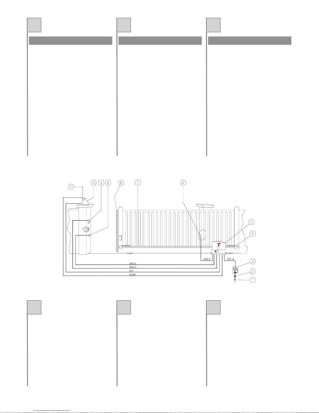
1. Lineadialimentazione
2. Interrutoregenerale
3. Interrutoredifferenziale
4. Staffadifinecorsa
5. Ace300
6. Fotocellula
7. Cremagliera
8. Costolasensibile
9. Selettoreachiaveotastieradigitale
10. Lampeggiatore
11. Antenna
1. Ligned'alimentation
2. Interrupteurgénéral
3. Interrupteurdifférentiel
4. Etrierdefindecourse
5. Ace300
6. Photocellule
7. Crémaillère
8. Tranchedesécurité
9. Sélécteuràcléetclasvierdigital
10. Clignotant
11. Antenne
1. Líneadealimentación
2. Interruptorgeneral
3. Interruptordiferencial
4. Aletasdetope
5. Ace300
6. Fotocélula
7. Cremallera
8. Nerviosensibile
9. Selectordellaveotecladodigital
10. Intermitente
11. Antena
QUADRO D'INSIEME TABLEAU D'ENSEMBLE CUADRO DE CONJUNTO
2
Page 3
GB D NL
Beforeinstalling,thefollowingchecks shouldbe
carriedout:
1. The structure of the gate should be solidand
suitable;
2.Readtheinstructionscarefully.
3.Ensurethatthereisnopointoftrictionduring
the gate and that there is no danger of
derailment.
4.The wiring mustberouted as specifiedbythe
controlandsafetyrequirements.
Vor de Installation ist es empfehlenswert, die
folgendenÜbertprüfungendurchzuführen:
1. Die Struktur des Tors muß solide und
geeignetsein;
2. Lesen Sie die Anleitungen aufmerksam
durch.
3. Sicherstellen, daß das Tor während der
gesamten Bewegung auf keine Reibpunktr
trifftundkeineEntgleisungsgefahrbesteht.
4. Bringen Sie einen Torstopper in
Öffnungsrichtung des Torflügels und nicht in
Schließrichtung an. Verlegen Sie die
StromkabelsowieimAnlagenbeispiel.
Het is verstandig om vóór de installatie de
volgentecontrolesteverrichten:
1. Het frame van de poort moet stevig en
geschiktzijn.
2.Leesdeaanwijzingenaandachtig.
3.Controleer ofertijdens dehelebeweging van
de poort geen wrijvingspunten zijn en of er
geengevaarvanontsporingis.
4. Breng een vleugelstop tijdens de opening en
een vleugelstop tijdens de sluiting aan en leg
deelektrischekabelsaanzoalsvermeld bijde
standaardinstallatie.
PRELIMINARYCHECKS VORBEREITENDE ÜBERPRÜFUNGEN CONTROLES VOORAF
GB D NL
1. Powersupplyline
2. On/Offswitch
3. Differentialswitch
4. Stopclamp
5. Ace300
6. Photocell
7. Rack
8. Sensitiverib
9. Keyselectorordigitalkeypad
10. Flashinglight
11. Antenna
1. Zufuhrleitung
2. Hauptschalter
3. Differentialschalter
4. Endschalterbügel
5. Ace300
6. Photozelle
7. Zahnstange
8. Kontaktschwelle
9. WahlschaltermitSclüsseloderTastfeld
10. Blinklicht
11. Antenne
1. Voedingslijn
2. Hoofschakelaar
3. Aardlekschakelaar
4. Aanslagbeugel
5. Ace300
6. Fotocel
7. Tandheugel
8. Contactdrempel
9. Sleutelschakelaarofdigitaaltoetsenbord
10. Knipperlicht
11. Antenne
GENERAL VIEW GESAMTANSICHT TOTAALBEELD
3
Page 4
IFE
ACE300
Motoriduttoreelettromeccanicoirreversibileper
cancellidalpesomaxdi300Kg.
Alimentazione monofase a 230 Vac,motore 24
Vdc.
Frizioneelettronica.
PignoneacremaglieraverticaleM4.
Completo di piastra di fissaggio e viti di
fissaggio.
ACE300
Motoréducteur électromécanique irréversible
pourportailsd'unpoidsmax.de300Kg.
Alimentation monophasée à 230 Vac,
.
Frictionélectronique.
PignonàcrémaillèreverticaleM4.
Dotéde plaqueetvisdefixation.
moteur à
24Vdc
ACE300
Motorreductor electromecánico para cancelas
depesomáxde300Kg.
Alimentaciónmonofásica a230Vac,
.
Fricciónelectrónica.
PiñónycremalleraverticalM4.
Se entrega con plancha para la fijación y
tornillosdefijación.
motora 24
Vc.c.
MODELLI E CARATTERISTICHE MODÈLES ET CARACTÉRISTIQUES MODELOS Y CARACTERÍSTICAS
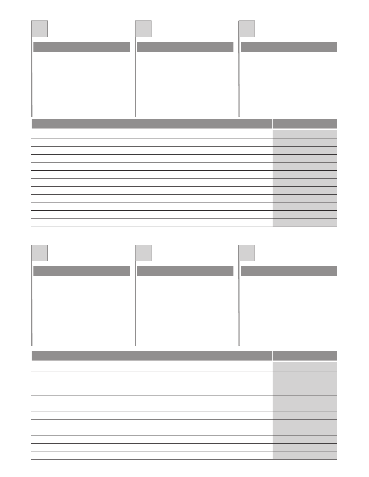
Alimentazione di rete
Alimentazione motore
Corrente max assorbita (230Vac)
Potenza max assorbita
Grado di protezione
Coppia nominale
Forza di spinta
Velocitàcancello
Temperatura di funzionamento
Intermittenza lavoro
Peso
DATI TECNICI DONNÉES TECHNIQUES DATOS TÉCNICOS U.M. Ace 300
GB D NL
ACE300
Irreversible electromechanical gearmotor for
gateswithmax.weightof300Kg.
Single-phase power supply of 230 Vac, m
.
Electronicclutch.
VerticalrackandpinionM4.
Completewith fixingplateandfixingscrews.
otor
powersupply24Vdc
ACE300
Elektromechanischer nicht umkehrbarer
Getriebemotor für Toremit einem Gewicht von
max.300Kg.
Einphasen-Versorgung230Vac, .
ElektronischeKupplung.
RitzelemitvertkalerZahnstangeM4.
Komplett mit Befestigungsplatte und
Befestigungsschrauben.
Motors24Vdc
ACE300
Onomkeerbare elektromechanische
motorreductor (met blokkering) voor poorten
meteenmax.gewichtvan300kg
Éénfasevoedingvan230Vac,
Elektronischekoppeling
RondselmetverticaletandheugelM4
Inclusief bevestigingsplaat en
bevestigingsschroeven.
Motorvoedingvan
24Vdc.
MODELSAND CHARACTERISTICS MODELLE UND EIGENSCHAFTEN MODELLEN EN SPECIFICATIES
TECHNICAL DATA TECHISCHE DATEN U.M. Ace 300TECHNISCHE GEGEVENS
4
230
24
1
120
44
30
340
0.18
-20
+50
60
7,5
Alimentation secteur
Alimentation moteur
Courant max absorbé (230Vac)
Puissance max absorbée
Degré de protection
Couple nominal
Force de poussée
Vitesse portail
Température de fonctionnement
Intermittence de fonctionnement
Poids
Alimentación de red
Alimentación motor
Corriente máx. absorbida (230Vac)
Potencia máx. absorbida
Grado de protección
Par nominal
Fuerza de empuje
Velocidadde la cancela
Temperatura de funcionamiento
Intermitencia de funcionamiento
Peso
Vca
Vdc
A
W
IP
Nm
N
M/sec
°C Min
Max
%
Kg
Mains power supply
otor power supply
Max current consumption (230Vac)
Max absorbed power
Protection rating
Nominal torque
Thrust force
Gate speed
Operating temperature
Duty cycle
Weight
230
24
1
120
44
30
340
0.18
-20
+50
60
7,5
Netzstromversorgung
Motorversorgung
Max. Stromaufnahme (230Vac)
Max. Leistungsaufnahme
Schutzart
Nenndrehmoment
Schubkraft
Torgeschwindigkeit
Betriebstemperatur
Intermittierender Betrieb
Gewicht
Stroomvoorziening van het elektriciteitsnet
Stroomvoorziening motor
Max. opname stroom (230Vac)
Max. opname vermogen
Beveiligingsklasse
Nominale koppel
Duwkracht
Snelheid poort
Bedrijfstemperatuur
Intermitterend bedrijf
Gewicht
Vca
Vdc
A
W
IP
Nm
N
M/sec
°C Min
Max
%
Kg
Page 5
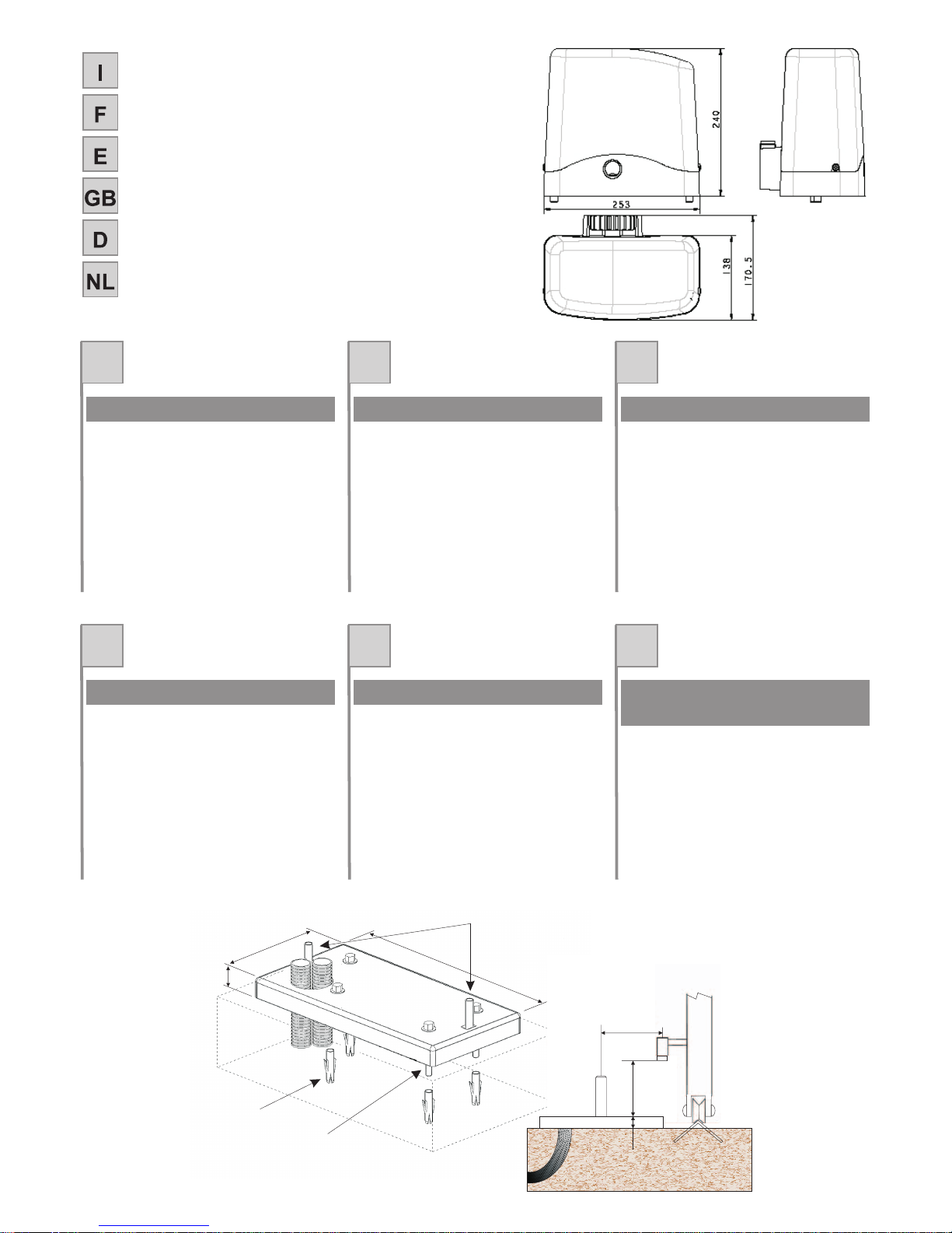
MISURE D'INGOMBRO
MEASURES
D'ENCOMBREMENT
MEDIDAS MAXIMAS EXTERNAS
OVERALL MEASUREMENTS
AUSSENABMESSUNGEN
MAATSCHETS
IFE
Rispettando le misure d'ingombro, fissare a
terra la piastra di base madiante 4 robusti
tasselli ad espansione (Fig.1 e Fig. 2) oppure
annegarlanelcalcestruzzo.
Prevedereuna o piùguaineper il passaggiodei
cavielettrici(Fig.1)
Prima di fissare la piastra sul
cemento, inserire le viti A per poter fissare il
motoriduttoresuccessivamente.
Importante!
En respectant les dimension d'encombrement ,
fixerau sol la plaque de base à l'aide de 4visà
expansion oubien noyer dans le
cimentlacontre-plaque.
Prévoiruneouplusieursgainespourlepassage
descâblesélectriques(Fig.1)
Avant de fixer la plaque sur le
ciment, introduire les vis Apour pouvoir fixer le
motoréducteurparlasuite.
(Fig.1e Fig. 2)
Important!
Respetandolasmedidasexternas,fijaralsuelo
la placa de base mediante 4 resistentes tacos
de expansión , o bien introducir
enhormigónlacontraplaca.
Prepararunao variasvainas paraelpasodelos
cableseléctricos(Fig.1)
Antes de fijar la placa sobre el
cemento, introduzca los tornillos A para poder
fijar,después,elmotorreductor.
(Fig.1 e Fig. 2)
¡Importante!
FISSAGGIO PIASTRADI BASE FIXATION PLAQUE DE BASE FIJACIÓN DE LAPLACA DE BASE
GB D NL
Observing the overall dimensions , fix the base
plate to the ground by means of 4 strong rawl
plugs or bury the counterplate in
theconcrete.
Plan for one more sheating for the passage of
thepowerlines(Fig.1)
Introduce screws A before fixing
the plate to the concrete in order for the
gearmotortobefixedafterwards.
(Fig.1eFig. 2)
Please note:
Die Grundplatte unter Beachtung der
Abmessungen mit vier soliden
ExpansionsdübelnamBodenbefestigen(Abb.1
-Abb.2)andemdiemitgeliefertePlattebefestigt
wird,indenBetoneingießen.
Ein oder mehrere Kabelrohre für die
Elektrokabelverlegen(Abb.1)
die Schrauben A vor der Befestigung
der Platte auf dem Beton einfügen, damit der
Getriebemotordanachbefestigtwerdenkann.
Wichtig:
Houd de totale afmetingen aan en bevestig de
onderplaatmet 4stevige spreidpluggen
opdegrondofstortdeplaatinhetbeton.
Breng één of meer kabeldoorvoeren voor de
elektrischekabelsaan (Fig.1).
Voordat u de plaat op het beton
gaat bevestigen dient u deschroevenA aam te
nremgem om later de reductiemotor te kunnen
bevestigen.
(Fig.1e
Fig.2)
Belangrijk!
FITTING THE BASE PLATE
BEFESTIGUNG DER GRUNDPLATTE
TECHNISCHE GEGEVENS
BEVESTIGING VAN DE
5
149
255
10
Fig.1/Abb.1
A
C
B
LATO CREMAGLIERA
85
10
86
Fig.2/ Abb. 2
Page 6
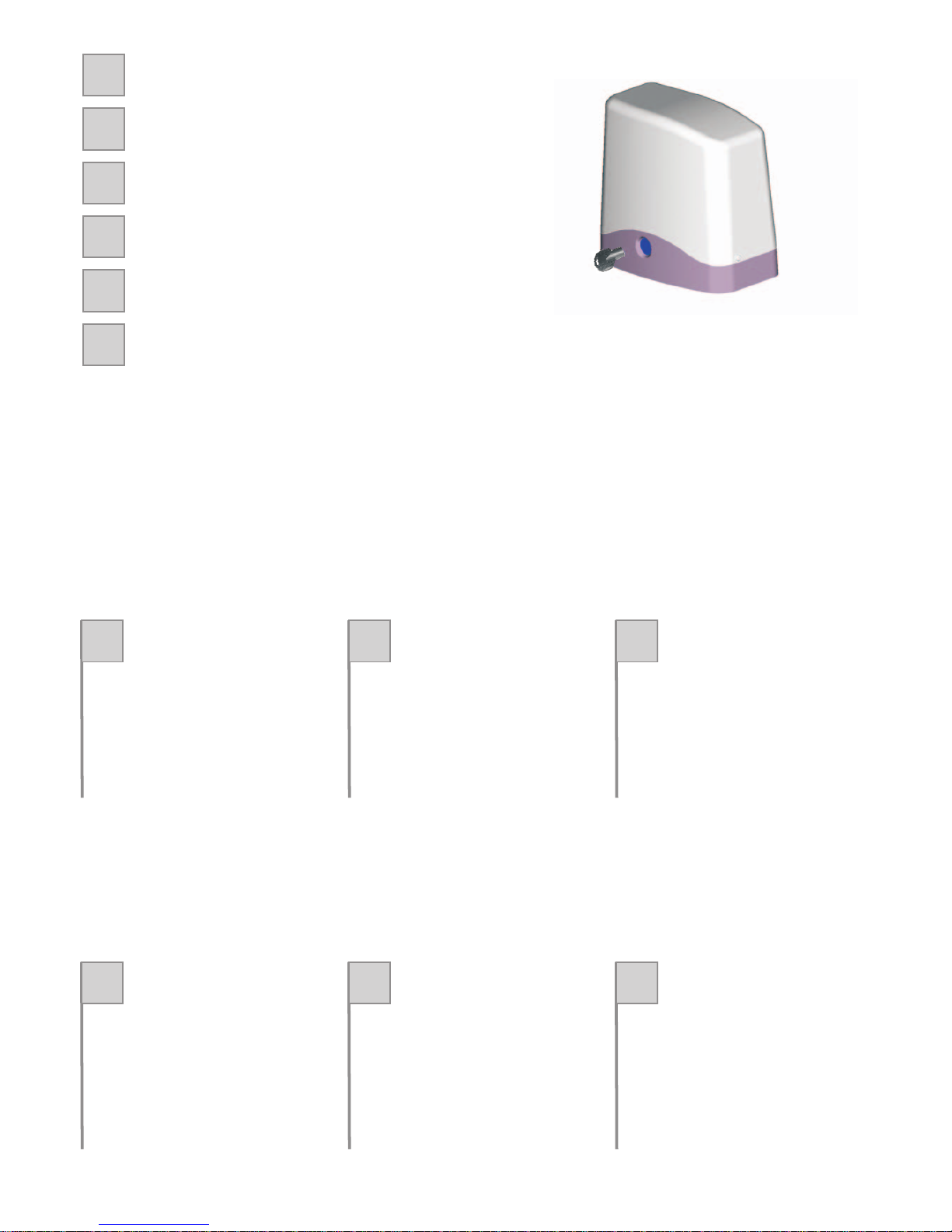
FUNZIONAMENTO MANUALE
FONCTIONNEMENT MANUEL
FUNCIONAMIENTO MANUAL
MANUAL OPERATION
MANUELLER BETRIEB
HANDMATIGE BEDIENING
F
I
E
GB
D
NL
IFE
Per sbloccare il motoriduttore alzare lo
sportellino, inserire la chiave e girare
completamente in senso antiorario sino a
quandoilcancellosimuoveliberamente.
Per bloccare il motoriduttore girare la chiave
completamente il senso orario e muovere
leggermenteilcancello.
Pour débloquer le motoréducteur, soulever le
volet, introduire la clé et tourner complètement
danslesensinverse aux aiguilles d'une montre
jusqu'àcequeleportailnebouge librement.
Pour bloquer le motoréducteur, tourner la clé
complètement dans le sens des aiguilles d'une
montreetfairebougerlégèrementleportail.
Para desbloquear el motorreductor, levante la
tapa, introduzca la llave y gire completamente
haciala izquierdahastaque lapuertase mueva
libremente.
Para bloquear el motorreductor gire la llave
completamente hacia la derecha y mueva
ligeramentelapuerta.
GB D NL
Toblockthegearmotor,lifttheflap,insertthekey
and turn it completely in an anticlockwise
directionuntilthegatemovesfreely.
To block the gearmotor,turn the key completely
in a clockwise direction and move the gate
slightly.
Um den Getriebemotor zu entriegeln, die Luke
heben, den Schlüssel einstecken und ganz
gegen den Uhrzeigersinn drehen, bis sich das
Torfreibewegt.
Um den Getriebemotor zu verriegeln, den
Schlüssel ganz im Uhrzeigersinn drehen und
dasTorleichtbewegen.
Voorhet ontgrendelen van de reductiemotor tilt
u het lipje omhoog, steekt de sleutel erin en
draaitdie helemaaltegen dewijzersvan deklok
inomtotdepoortvrijelijkkanbewegen.
Om de reductiemotor te vergrendelen draait u
de sleutel helemaal om met de wijzers van de
klokmeeenverplaatstzachtjesdepoort.
6
Fig. 3/Abb. 3
Page 7

IFE
Togliereilcoperchiosvitandoleviti(fig.4).
Appoggiare il motoriduttore sulla piastra,
avvitareidadialleduevitiA(fig.5).
Prima di avvitare a fondo i 2 dadi, è possibile
regolare la distanza del motore dalla
cremaglieraagendosullevitiindicateinfig.6.
Inseguitoèimportantebloccareenergicamente
i due dadi M12 (fig. 5), assicurandosi che
durante tutta la corsa del cancello, il
motoriduttoresiabensaldoaterra.
Enleverlecouvercleendévissantlesvis(fig.4).
Poserle motoréducteur surlaplaque, visser les
écrousauxdeuxvis
Avant de visser à fond les 2 écrous, on peut
régler la distance du moteur de lacrémaillère à
l'aidedesvisindiquéessurlafig.6.
Ensuite, il est important de bloquer
énergiquementlesdeuxécrousM12(fig.5),en
s'assurantque durant toute lacoursedu portail,
lemotoréducteursoitsolidementfixéausol.
A(fig.5).
Quitar la tapa destornillando los dos tornillos
(fig.4)
Apoye el motorreductor sobre la placa,
enrosque las tuercas en los dos tornillos
Antesde enroscar hasta el fondo las 2 tuercas,
esposibleregularladistanciaentreelmotoryla
cremallera, utilizando los tornillos indicados en
lafig.6.
Luego, es importante bloquear bien fuerte las
dos tuercas M12 (fig. 5), controlando que el
motorreductorquedebien fijado al piso durante
todalacarreradelacancela.
A(fig.
5).
FISSAGGIO MOTORIDUTTORE FIXATION MOTORÉDUCTEUR FIJACIÓN DEL MOTORREDUCTOR
GB D NL
Removethecoverunscrewingthescrews(fig.4)
Position the gearmotor on the baseplate and
tightenthenutsonthetwoscrews
Before tightening the two nuts fully down you
can adjust the distance of the motor from the
rack,bymeansofthescrewsshowninFig.6.
NowtightenthetwoM12nutsfully down(Fig.5),
making sure that the gearmotor is firmly
anchoredtothe ground throughout the range of
gatetravel.
A(fig.5).
Die Schrauben lösen und den Deckel
abnehmen(abb.4).
Den Getriebemotor auf die Platte legen; die
Mutternaufden beiden Schrauben anbringen
Bevor die beiden Muttern fest angezogen
werden, kann die Entfernung des Motors von
der Zahnstangedurch BetätigungderinAbb.6
gezeigtenSchraubenreguliertwerden.
Danach müssen die beiden M12 Muttern (Abb.
5) fest angezogen werden, so dass der
Getriebemotorwährend des gesamten Torlaufs
gutmitdemBodenverankertbleibt.
A
(Abb.5).
Haal de kap eraf door de schroeven eruit te
draaien(fig.4).
Laat de reductiemotor op deplaat rusten, draai
demoerenopdetweeschroevenvast
Voordatu de 2 moeren helemaal vast draait, is
het mogelijk de afstand van de motor tot de
tandheugel af te stellen; u doet dit met behulp
vandeschroevendieopafb.6zijnaangegeven.
Vervolgensdientu -enditisbelangrijk-detwee
moeren M12 (afb. 5) stevig aan te draaien,
waarbiju zichervan dienttevergewissen datde
reductiemotoroverde gehele loop van de poort
stevigopdegrondblijft.
A(fig.5).
FITTING THE GEARMOTOR BEFESTIGUNG DESANTRIEBS BEVESTIGING VAN DE
MOTORREDUCTOR
fig. 4/Abb. 4 fig. 5/Abb. 5
A
fig. 6/Abb. 6
7
Page 8

IFE
Sbloccare il motoriduttore nel modo indicato in
Fig.3 e portare il cancello in completaapertura.
Appoggiare un elemento di cremagliera al
pignone e fissare lo stesso con viti e distanziali
alcancello.
Spostare manualmente il cancello portando il
pignone in corrispondenza dell'ultimo
distanziale. Fissare l'elemento di cremagliera
definitivamente.
Per un corretto posizionamento degli altri
elementi e garantire la loro rettilineità, è
necessario utilizzare un elemento di
cremagliera usandolo come appoggio e
referimento(fig.10).
Si deve garantire un'aria fra cremagliera e
pignonedi 2mm,così danon fargravareil peso
del cancello sul pignone del motoriduttore
(fig.9).
Nel caso di cancelli nuovi verificare in tempi
successivi all'installazione il gioco fra
cremagliera e pignone, se necessario agire
sulle asole della cremagliera per registrare i
giochi.
N.B.
Débloquer le motoréducteur (voir “Fonctionnementmanuel”)ouplacerenpositiond'ouverture
totale.
Appuyerunélémentdecrémaillèreaupignonet
le fixer au portail à la l'aide de vis et
d'entretoises.
Déplacer manuallement le portail afin de faire
correspondre le pignon et la dernière
entretoises.
Fixerdéfinitivementl'élémentdecrémaillère.
Il est nècessaire d'utiliser un élément de
crémaillère comme appui et point de référence
afin de pouvoir positionner correctement les
autres éléments et de garantir leur alignement
(fig.10).
Assurer toujours un jeu d'1 mm entre la
crémaillère et le pignon de façon à ce que le
poids du portail ne repose pas sur le pignon du
motoréducteur.(fig.9).
Si le portail est neuf, contrôler, quelque temps
après l'installation, le jeu entre pignon et
crémaillère ; si une modification du jeu est
nècessaireagirsurlesfentesdelacrémaillère.
N.B.
Desbloquear el motorreductor (ver
“Funcionamiento manual”) o llevar lacancela a
lacompletaapertura.
Apoyar un elemento de cremallera al piñón y
fijarlocontornillosydistanciadoresalacancela.
Desplazarmanualmente la cancelahastallevar
elpiñónalaalturadeúltimodistanciador.
Fijardefinitivamente el elementodecremallera.
Para un posicionamiento correcto de los otros
elementos de cremallera y para garantizar su
rectinilidad,esnecesarioutilizar unelementode
cremalleracomoapoyoyreferencia(fig.10).
Controlarqueentre cremalleray piñónexistaun
espaciode1mmparaqueelpeso dela cancela
no caiga sobre el piñón del motorreductor
(fig.9).
En el caso de cancelas nuevas, controlar,
después de la instalación, el juego entre
cremallera u piñón ; si es necesario registrar el
juego « cremallera/piñón” por medio de las
ranurasdelacremallera.
Nota:
MONTAGGIO CREMAGLIERA MONTAGE CREMAILLERE MONTAJE CREMALLERA
Fig. 10/Abb. 10Fig. 9/Abb. 9
85 mm
2mm
10
85
86mm
8
Page 9

GB D NL
Release the gearmotor (see “Manual
operation”)orfullyopenthegate.
Restarack elementon thepinionandfixittothe
gateusingscrewsandspacers.
Movethe gate manuallyuntilthe pinion isinline
withthelastspacer.
Move the gate manually intil the pinion is inline
withthelastspacer.
Permanentlyfixtherackelement.
A rack element must be used as resting and
referencepointinordertopositiontheotherrack
elements correctly and make sure they are in a
straightline(fig.10).
Makesurethatthereisaspace of1mmbetween
therackandthepinion so that the weight of the
gate does not rest on the gearmotor pinion
(fig.9).
With new gates, check the backlash or play
between rack and pinion at intervals following
installationandifnecessaryadjustbymeansof
theslotsintherack.
N.B.
Den Getriebemotor deblockieren (siehe
“Manueller Betrieb”) und das Tor vollständig
öffnen.
Ein Element der Zahnstange an den Kolben
anlegen und mit Schraauben und
AbstandsstückenamTorbefestigen.
DasTor manuell versetzen, bis daß der Kolben
in Übereinstimmung mit dem letzten
Abstandsstückgebrachtist.
Das Element der Zahnstange definitiv
befestigen.
Für eine einwandfreie Plazierung der anderen
Zahnstangenelemente und um deren
geradlinigeAusrichtungzu gewährleisten,istes
notwendig, ein Zahnstangenelement als
AuflageundReferenzzuverwenden(abb.10).
Sicherstellen, daß zwischen Zahnstange und
KolbeneinZwischenraum von1 mmbesteht,so
daß das Gewicht des Tors den Kolben des
Getriebemotorsnichtbelastet(abb.9).
Beineuen Toren inderZeit nachderInstallation
das Spiel zwischen Zahnstange und Kolben
überprüfen; falls notwendig die Löcher der
Zahnstange betätigen, um das Spiel
„Zahnstange/Kolben“einzustellen.
Hinweis:
Ontgrendel de motorreductieaandrijving (zie
“handbediende werking”) of zet het hek
helemaalopen.
Leg een element van de tandheugel op het
tandwielen maakditelement metschroevenen
afstandshoudersaanhethekvast.
Verplaats het hek met de hand totdat het
tandwiel zich ter hoogte van de laatste
afstandshouderbevindt.
Maakhettandheugelelementdefinitiefvast.
Om ervoor te zorgen dat de andere elementen
vandetandheugelopdejuiste plaats komen te
zitten en om er zeker van te zijn dat de
elementen recht zitten moet u één
tandheugelelement als steun en als
uitgangspuntnehmen(fig.10).
Controleer of er tussen de tandheugel en het
tandwiel1 mm speling zitzodathetgewicht van
het hek geen belasting voor de
motorreductieaandrijvingvormt(fig.9).
Bij nieuwe hekken moet u na de installatie de
speling tussen de tandheugel en het tandwiel
regelmatigcontroleren ; indien nodig moet u de
speling tussen de tandheugel en het tandwiel
met behulp van gleuven van de tandheugel
afstellen.
N.B.
RACKASSEMBLY MONTAGE DER- ZAHNSTANGE DE TANDHEUGEL MONTEREN
9
Fig. 10/Abb. 10Fig. 9/Abb. 9
85 mm
2mm
10
85
86mm
Page 10

IFE
Gli ACE300 montano un finecorsa elettronico
non visibile dall'esterno indicato in figura 7 con
laletteraS.
Posizionare le staffe con i magneti M e fare
attenzione a che ciascuna staffa sia
sufficientemente vicina al finecorsa elettronico
S in modo da garantire lo stop del motore. La
distanza da tenere tra magnete M eil finecorsa
S deve essere compresa fra i 2 ed i 8 mm
massimo.
Portare manualmente il cancello in apertura,
evitando che vada in battuta contro il fermo
meccanico,fissarequindilastaffa del finecorsa
medianteigrani (fig./Abb8) inmodocheilpunto
(M) in Fig./Abb.7 sia al centro del pignone (S).
Fare riferimento anche alle istruzioni della
centralinaelettronica
Les ACE300 ont un fin de course électronique
non visible de l'extérieur indiqué sur la figure 7
parlalettreS.
Placer les étriers avec les aimants M et faire
attention à ce que chaque étrier soit
suffisamment proche du fin de course
électronique S de manière à garantir l'arrêt du
moteur.Ladistance à garderentrel'aimant M et
lefin de course Sdoitêtre comprise entre 2et8
mmmaximum.
Amener manuellement le portail en ouverture,
enévitant qu'ilne butecontrel'arrêt mécanique,
fixerensuitel'étrierdu fin de course à l'aide des
goujons (fig./Abb 8) de façon à ce que le point
(M) sur la Fig./Abb.7 soit au centre du pignon
(S). Se reporter aussi aux instructions de la
centraleélectronique.
Los ACE300 montan un fin de carrera
electrónico no visible desde afuera, indicado
conlaletraSenlafigura7.
Coloquelasplacas con imanes M y compruebe
que cada placa esté suficientemente cerca del
fin de carrera electrónico S para garantizar la
paradadelmotor. Ladistanciaentrelos imanes
M y el fin de carreraS debe estar comprendida
entre2y8mmcomomáximo.
Abra manualmente la cancela sin que toque el
topemecánico,fijelaplacadelfindecarreracon
los tornillos sin cabeza (fig./Abb 8), de manera
que el punto (M) de la Fig./Abb.7 quede en el
centro del piñón (S). Consulte también las
instruccionesdelacentralelectrónica.
FISSAGGIO FINECORSA
FIXATION BUTTÉES FINS DE COURSE
FIJACIÓN DE LAALETAS DE TOPE
GB D NL
ACE300 units are equipped with an electronic
limit switch indicated by letter S in figure 7 (the
limitswitchisnotvisiblefromtheoutside).
Position the brackets with magnets (M) and
makesure thateachbracket is sufficientlyclose
to the electronic limit switch (S) to as to ensure
the motor is stopped. There must be a gap of
between 2 and 8 mm between magnet (M) and
limitswitch(S).
Manually open the gate without it touching the
mechanical stop, and then fix the limit switch
bracket using the grub screws (Fig./Abb. 8) so
that point (M) in Fig./Abb. 7 is at the centre of
pinion (S). Refer also to the instructions for the
electroniccontrolunit.
Die Torantriebe ACE300 verfügen über einen
von außen nicht sichtbaren, elektronischen
Endschalter, der in Abbildung 7 mit dem
BuchstabenSangegebenist.
Die Bügel mit den Magneten M anbringen und
daraufachten,dasssichjeder Bügel genügend
nah am elektronischen Endschalter S befindet,
sodassdas AnhaltendesMotorsgewährleistet
ist. Die Entfernung zwischen Magnet M und
EndschalterS musszwischen max.2und 8mm
sein.
Das Tor von Hand so weit öffnen, dass es den
mechanischen Endanschlag nicht erreicht,
dann den Endschalterbügel mit den
Stiftschrauben(Abb. 8)so befestigen,dass sich
der Punkt (M) inAbb. 7 in der Mitte des Ritzels
(S) befindet. Auch auf die Anweisungen der
elektronischenSteuerungBezugnehmen.
Op de ACE300 is een elektronische
eindschakelaar gemonteerd die van buitenaf
nietzichtbaaris; opafbeelding7wordtdeze met
deletterSaangeduid.
Plaats de beugels met de magneten M en let
erop dat elke beugel zich dicht genoeg bij de
elektronische eindschakelaar S bevindt, zodat
de motor gegarandeerd stopt. De tussen de
magneet M en de eindschakelaar S aan te
houden afstand dient tussen de 2 en ten
hoogste8mmteliggen.
Zetdepoort handmatig open en vermijd daarbij
dat die tegen de mechanische stop komt; zet
daarna de beugel van de eindschakelaar met
stifttappenzo vast (afb./Abb 8) dat het punt (M)
opAfb./Abb.7zichinhetmiddenvan hetrondsel
(S) bevindt. Raadpleeg ook de aanwijzingen
vandeelektronischebesturingseenheid.
ATTACHING THE SWITCH TABS
MONTAGE DE ENDSCHALTERBÜGEL
BEVESTIGING VAN DE
EINDSCHAKELAARS
M
Max8mm
M
Fig. 7/Abb. 7
S
Fig. 8/Abb. 8
10
Page 11

IFE
Ace300 è provvisto di una sede per poter
installare due batterie tampone da 12V 1.2Ah,
che collegate opportunamente alla centralina
elettronica possono garantire, per un tempo
limitato,l'apertura ela chiusuradell'antain caso
mancassel'alimentazionedilinea.(Fig./Abb.11)
Ace300 est muni d'un logement pour pouvoir
installer deux batteries tampon de 12V 1.2Ah,
qui,reliées de manière appropriée à la centrale
électronique, peuvent garantir pendant un
temps limité, l'ouverture et la fermeture du
vantail en cas de coupure d'alimentation de
ligne.(Fig./Abb.11)
Ace300 está dotado de un alojamiento para
instalar dos baterías compensadoras de 12V
1.2Ah, que, al estar conectadas a la central
electrónica, pueden garantizar, durante un
tiempo limitado, la apertura y el cierre de la
puerta si faltara la alimentación de línea
(Fig./Abb.11).
BATTERIE TAMPONE
BATTERIES TAMPON
BATERÍAS COMPENSADORAS
GB D NL
ACE300featuresahousingdesigned to accept
two 12V 1.2A back-up batteries which, when
connected to the electronic control unit, will
provide sufficient power to open and close the
gate for a limited time in the case of a mains
powerfailure(Fig./Abb.11).
Ace300 verfügt über ein Abteil zum Einbau von
zwei 12V 1.2Ah Pufferbatterien, die wenn
korrekt mit der elektronischen Steuerung
verbunden dasÖffnen und Schließen des Tors
bei Stromausfall für eine bestimmte Zeit
garantierenkönnen(Abb.11).
OpdeACE300 iseenplaats gereserveerdwaar
twee bufferbatterijen van 12V 1.2Ah
gemonteerdkunnenworden. Wanneerdeze op
de elektronische besturingseenheid zijn
aangesloten kunnen zij voor een bepaalde tijd
het openen en sluiten van de vleugel
garanderen, mocht de stroom van het
elektriciteitsnetuitvallen.(Afb./Abb.11)
BATTERIES WHICH
PUFFERBATTERIEN
BUFFERBATTERIJEN
11
Fig. 11/Abb.11
2X
TIPO: 12V 1,2Ah
DIM : 44x98x52mm
Cb24
Page 12

IFE
Il cancello non apre o non chiude ; il motore
elettrico non funziona e non si avverte,
quindi,alcunrumoreovibrazione:
Il cancello non apre; il motore funziona ma
nonavvieneilmovimento:
1.Verificare che la centralina elettronica sia
regolarmentealimentata.
2.Verificarel'efficienzadeifusibili.
3.Verificare, con l'ausilio di adeguati strumenti
diagnostici, che le funzioni
dell'apparecchiatura elettronica siano
corrette.
4.Accertarsicheilmotorericevaalimentazione.
1.Verificareche il pignona dentato sia in presa
conlacremagliera.
2.Controllare che il motoriduttore non sia
sbloccato.
Può darsi che il motoriduttore sia bloccatoda
uno dei due arresti meccanici; in tal caso
bisogna sbloccare manualmente il motore,
azionare il cancello a mano, liberandolo da
quella posizione anomala e, prima di
ripristinare il funzionamento automatico,
posizionare correttamente le staffe di
finecorsa.
Le portail nes'ouvrepasetnese ferme pas.
Lemoteur nefonctionne paset doncaucune
rumeurnivibrationnepeutêtreperçue
Le portail ne s'ouvre pas, le moteur
fonctionne sans que ne se produise de
mouvement.
.
1.Vérifier que la centrale électronique de
commandesoitnormalementalimentée.
2.Vérifierl'étatdesfusibles.
3.Vérifier, à l'aide d'instruments de diagnostic
adéquats, que les fonctions de la centrale
électroniquesoientnormales.
4.S'assurerquelemotoréducteurestalimenté.
1.Vérifierquelepignondentésoitenpriseavec
lacrémaillère.
2.Contrôlerquelemotoréducteurnesoitpas en
position«manuelle»(débloqué).
Contrôler que le motoréducteur ne soit pas
bloqué par un des deux arrêts mécaniques.
Dans ce cas-là, débloquer manuellement le
moteur et actionner le portail à la main, en le
libérant,dece fait,de cettepositionanormale.
Placer correctement les étriers de fin de
course et rétablir le fonctionnement
automatique.
La cancela no se abre ni cierra, el motor no
funciona y no se advierte, por lo tanto,
ningúnruidoovibración.
La cancela no abre. El motor funciona, pero
noserealizaelmovimiento.
1.Controlar que la caja de mandos electrónica
estéregularmentealimentada.
2.Controlarlaeficienciadelosfusibles.
3. Verifcar, con la ayuda de adecuados
instrumentos diagnósticos; que las funciones
de la caja de mandos electrónica sean
correctas.
4. Asegurarse que el motorreductor reciba
alimentación.
1. Controlar que el piñón dentado engrane con
lacremallera.
2. Controlar que el motorreductor no esté en
posición“manual”(desbloqueado).
Controlar que el motorreductor no esté
bloqueado por uno de los dos paros
mecánicos. En tal caso desbloquear
manualmenteelmotoryaccionarla cancelaa
mano soltándola, de este modo, de esta
situación anómala. Posicionar, luego,
correctamente las abrazaderas de los topes
de recorrido y restablecer el funcionamiento
automático.
ANOMALIE DI FUNZIONAMENTO.
RIMEDI
ANOMALIES DE
FONCTIONNEMENT.
REMEDES
ANOMALIAS DE
FUNCIONAMIENTO.
REMEDIOS
12
Page 13

GB D NL
The gate neither opens nor closes. The
motor does not work and there is
consequentlynonoiseorvibration.
The gate does not open. The motor works
butthereisnomovement.
1.Check that the electronic control unit is
regularlypowered.
2.Checkthefuses.
3.Using suitable diagnostic instruments, check
that the electronic unit is in proper working
order.
4.Makesurethatthegearmotorispowered.
1.Check that the toothed pinion is in mesh with
therack.
2.Check that the gearmotor is not in the
“manual”position(released).
Check that the gearmotor is not locked in
placebyoneormoremechanicalstops.Ifitis,
releasethemotormanuallyandmovethegate
byhandtofreeit.Finallycorrectthepositionof
the stop clamps and reset automatic
operation.
DasToröffnetundschließtsichnicht.
DerMotor funktioniert nicht undes ist daher
keinerlei Geräusch oder Vibration
wahrnehmbar.
Das Tor öffnet sich nicht. Der Motor
funktioniert, es erfolgt jedoch keinerlei
Bewegung.
1.Überprüfen, daß die elektronische
Steuereinheit ordnungsgemäß unter
Spannungsteht.
2.Die Leistungsfähigkeit der Sicherungen
überprüfen.
3.Mit Hilfe der entsprechenden
Diagnoseinstrumente überprüfen, daß die
Funktionen der elektronischen Steuereinheit
einwandfreisind.
4.Sicherstellen, daß der Getriebemotor unter
Spannungsteht.
1.Überfrüfen, daß der gezahnte Kolben in die
Zahnstangegreift.
2.Kontrollieren, daß sich der Getriebemotor in
der “manuellen“ Stellung (deblockiert)
befindet.
Kontrollieren, daß der Getriebemotor nicht
von einer der beiden mechanischen
Verriegelungen blockiert ist. In diesem Fall
den Motor manuell deblokieren und das Tor
perHandbetätigen und aus dieser anomalen
Position befreien. Danach die Bügel der
Endschalter korrekt positionieren und den
Automatikbetriebwiederherstellen.
Het hak gaat open en niet dicht. De motor
functioneert niet en u neemt dan ook geen
enkelgeluidoftrillingwaar.
Het hek gaat niet open. Den motor
functioneert, maar er vindt ondanks dat
gennbewegingplaats.
1.Controleer of de elektronische
besturingseenheid op correcte wijze stroom
toegevoerdkrijgt.
2.Controleerofdezekeringenefficiëntzijn.
3.Controleer met behulp van geschikte
diagnose-apparatuur of de elektronische
besturingseenheidgoedfunctioneert.
4.Controleer of de motorreductieaandrijving
stroomtoegevoerdkrijgt.
1.Controleer of het tandwiel goed in de
tandheugelingrijpt.
2.Gana de motorreductieaandrijvingniet op de
“handbedieningsstand”staat(ontgrendeldis).
Ga na dat de motorreductieaandrijving niet
geblokkeerdis door één van de mechanische
aanslagen. In dat geval moet u de motor met
dehanddeblokkerenenhet hek met de hand
inwerkingstellenen uitdezeabnormalestand
bevrijden. Zet de beugels van de aanslagen
daarna in de goede stand en herstel de
automatischewerking.
OPERATING PROBLEMS.
REMEDIES
BETRIBSSTÖRUNGEN.
BEHEBUNG
STORINGEN EN OPLOSSINGEN
13
Page 14

IFE
1. L'installazione dell'automazione deve essere
eseguita a regola d'arte da personale qualificato
aventei requisiti dilegge efatta in conformitàdella
direttiva macchine 98/37/CE e alle normative EN
12453eEN12445.
2. Verificare la solidità delle strutture esistenti
(colonne, cerniere, ante) in relazione alle forze
sviluppatedalmotore.
3. Verificare che vi siano dei fermi meccanici di
adeguata robustezza a fine apertura e fine
chiusuradelleante.
4. Fare un'analisi dei rischi dell'automazione e di
conseguenza adottare le sicurezze e le
segnalazioninecessarie.
5. Installare i comandi (ad esempio il selettore a
chiave)in modoche l'utilizzatorenon sitrovi in una
zonapericolosa.
6. Terminata l'installazione provare più volte i
dispositivi di sicurezza, segnalazione e di sblocco
dell'automazione.
7. Applicare sull'automazione l'etichetta o la
targhetta CE contenenti le informazioni di pericolo
eidatidiidentificazione.
8. Consegnare all'utilizzatore finale le istruzioni
d'uso, le avvertenze per la sicurezza e la
dichiarazioneCEdiconformità.
9. Accertarsi che l'utilizzatore abbia compreso il
corretto funzionamento automatico, manuale e di
emergenzadell'automazione.
10. Informare l'utilizzatore per iscritto (ad esempio
nelle istruzioni d'uso) dell' eventuale presenza di
rischi residui non protetti e dell'uso improprio
prevedibile.
11. Predisporre un piano di manutenzione
dell'impianto(almeno ogni6 mesiper le sicurezze)
riportando su di un apposito registro gli interventi
eseguiti.
Questo prodotto è formato da vari componenti che
potrebbero a loro volta contenere sostanze
inquinanti.Nondisperderenell'ambiente!
Informarsisulsistemadi riciclaggioosmaltimento del
prodotto attenendosi alle norme di legge vigenti a
livellolocale.
1. L'installation de l'automation doit être effectuée
danslesrègles del'artpardu personnelspécialisé,
conformément aux dispositions légales, à la
directive machine 98/37/CE et aux normes EN
12453etEN12445.
2. S'assurerque lesstructures existantes (colonnes,
charnières, vantaux) soient suffisamment solides
pourrésisterauxforcesdéveloppéesparlemoteur.
3. S'assurer que les arrêts mécaniques en fin
d'ouverture et en fin de fermeture des vantaux
soientsuffisammentrobustes.
4. Faire une analyse des risques de l'automation et
adopter, en fonction de celle-ci, les dispositifs de
sécuritéetdesignalisationnécessaires.
5. Installerlescommandes(par exemplelesélecteur
àclé) demanière àce quel'utilisateur ne setrouve
pasdansunezonedangereuse.
6. Unefoisl'installationterminée,testerplusieursfois
les dispositifs de sécurité, de signalisation et de
déverrouillagedel'automation.
7. Appliquer sur l'automation l'étiquette ou la plaque
CE où sont indiqués les dangers présentés par
l'automation ainsi que les données d'identification
delamachine.
8. Remettre à l'utilisateur final le mode d'emploi, les
avertissements concernant la sécurité et la
déclarationCEdeconformité.
9. S'assurer que l'utilisateur a bien compris le
fonctionnementautomatique, manuel etd'urgence
del'automation.
10.Informerparécritl'utilisateur(parexempledansle
moded'emploi)del'éventuelleprésencederisques
résiduelsnoncouvertsetdesutilisationsimpropres
prévisibles.
11.Etablir unplandemaintenancedel'installation(au
moins tous les 6 mois pour les dispositifs de
sécurité) en inscrivant sur un registre prévu à cet
effetlesinterventionseffectuées.
Ce produit est constitué de divers composants qui
pourraient à leur tour contenir des substances
polluantes. Ne pas laisser ce produit gagner
l'environnement.
S'informer sur le système de recyclage ou
d'élimination du produit conformément aux
dispositionslégalesenvigueuràunniveau local.
1. Lainstalacióndel automatismodebe ser realizada
según los cánones, por personal cualificado que
reúna los requisitos establecidos por la ley y de
conformidad con la Directiva sobre máquinas
98/37/CEyconlasnormasEN12453yEN12445.
2. Compruebe la solidez de las estructuras
existentes(columnas, bisagras, hojas) en relación
conlasfuerzasdesarrolladasporelmotor.
3. Controle que haya retenes mecánicos de solidez
adecuada en los puntos de fin de apertura yde fin
decierredelashojas.
4. Hagaun análisisde losriesgos delautomatismo y
adopte los dispositivos de seguridad y las
señalizacionesnecesariasenconsecuencia.
5. Instale los mandos (por ejemplo, el selector de
llave)demaneraque elusuarionose encuentre en
unazonapeligrosa.
6. Terminada la instalación, pruebe varias veces los
dispositivos de seguridad, señalización y
desbloqueodelautomatismo.
7. Aplique en el automatismo una etiqueta o una
placa CE que contenga las informaciones de
peligroylosdatosdeidentificación.
8. Entregue al usuario final las instrucciones para el
uso, las advertencias para la seguridad y la
declaraciónCEdeconformidad.
9. Asegúresedeque elusuario hayacomprendidoel
correcto funcionamiento automático, manual y de
emergenciadelautomatismo.
10.Informeal usuariopor escrito(porejemplo, enlos
manuales de instrucciones) de la eventual
presenciaderiesgosresidualesnoprotegidosydel
usoinadecuadoprevisible.
11.Predisponga un programa de mantenimiento de
la instalación (al menos cada 6 meses para los
dispositivosdeseguridad),anotandoenunregistro
expresamente dedicado las intervenciones
realizadas.
Este producto está constituido por varios
componentes que podrían, a su vez, contener
sustanciascontaminantes. ¡Nolos viertaen el medio
ambiente!
Infórmesesobre elsistema dereciclaje oeliminación
del producto con arreglo a las leyes vigentes en
ámbitolocal.
RACCOMANDAZIONI
FINALI
RECOMMANDATIONS
FINALES
RECOMENDACIONES
FINALES
14
SMALTIMENTO ELIMINATION ELIMINACION
Page 15

GB D NL
1. Only qualified personnel having the legal
requirements must install the automation
according to the principles of good workmanship
and in conformity with the machinery directive
98/37/CEandstandardsEN12453andEN12445.
2. Check that the existing structures (posts, hinges,
leaves) are stable in relation to the forces
developedbythemotor.
3. Check that suitably robust limit stops have been
installedforendofgateopeningandclosing.
4. Analyse the hazards connected with the
automationsystemandadopt thenecessarysafety
andsignallingdevicesaccordingly.
5. Installthecommands(e.g.thekeyselector)sothat
the user is not placed in a hazardous area when
usingthem.
6. Uponcompletionof theinstallation, testthe safety,
signalling and release devices of the automation
systemseveraltimes.
7. Apply the CE label or plate with information
regardingthehazardsandidentificationdataonthe
automation.
8. Give the end user the instructions for use, the
safetyrecommendations and theCE declarationof
conformity.
9. Ensure that the user has understood the correct
automatic,manualandemergency operationofthe
automationsystem.
10. Inform the user in writing (e.g. in the instructions
for use) of any unprotected residual risks and of
foreseeablemisuse.
11. Prepare a maintenance schedule for the
automation installation (at least once every 6
months for the safety devices), recording the work
carriedoutinaspecialbook.
This product is made up of various components that
couldcontainpollutants.Disposeofproperly!
Make enquiries concerning the recycling or disposal
oftheproduct,complyingwiththelocallawsinforce.
1. Die Installation der Automatisierung muss in
Übereinstimmung mit der Maschinenrichtlinie
98/37/EU und den Bestimmungen EN 12453 und
EN 12445, fachgerecht und von qualifiziertem
Personal, das die gesetzlichen Anforderungen
erfüllt,vorgenommenwerden.
2. DieStabilitätdervorhandenenStrukturen(Säulen,
Scharniere, Flügel) im Hinblick auf die vom Motor
entwickeltenKräfteüberprüfen.
3. Sicherstellen,dass am Öffnungsanschlagund am
SchließanschlagderTorflügelausreichend robuste
mechanische Feststellvorrichtungen vorhanden
sind.
4. Die Risiken, die durch die Automatisierung
entstehen können, abwägen und
dementsprechende Sicherheitsvorkehrungen
treffen, sowie die erforderlichen Warnhinweise
anbringen.
5. Die Steuerungen (z.B. Schlüsselschalter) so
installieren, dass sich der Benutzer nicht in einem
Gefahrenbereichaufhaltenmuss.
6. Nach abgeschlossener Installation mehrmals die
Sicherheits-, Anzeige- und Entsperrvorrichtungen
derAutomatisierungerproben.
7. Auf der Automatisierung die EU- Etikette oder das
EU-Schildanbringen,auf demdieGefahrenhinweise
unddieKenndatenaufgeführtsind.
8. Dem Endkunden die Bedienungsanweisung, die
Sicherheitshinweise und die EUKonformitätserklärungaushändigen.
9. Sicherstellen, dass der Bediener die korrekte
automatische und manuelle Funktionsweise sowie
denNotbetriebderAutomatisierungverstandenhat.
10. Den Benutzer schriftlich (beispielsweise in der
Bedienungsanweisung) über das Vorhandensein
etwaiger, nicht abgesicherter Restrisiken und über
eine vorhersehbare, missbräuchliche Benutzung,
informieren.
11.EinenWartungsplan fürdie Anlagevorbereiten (die
Sicherheitsvorrichtung müssen mindestens alle 6
Monate gewartet werden) und die ausgeführten
Wartungseingriffe in einem entsprechenden
Verzeichnisanmerken.
Dieses Produkt besteht aus verschiedenen
Bauteilen,die ihrerseits dieUmwelt verschmutzende
Stoffeenthaltenkönnen.Sachgerechtentsorgen!
Informieren Sie sich, nach welchem Recycling- oder
Entsorgungssystem das Produkt entsprechend der
örtlichgeltendenBestimmungenzuentsorgenist
1. De installatie van de automatisering moet op
deugdelijke wijze uitgevoerd worden door
vakmensendie aan de wettelijkeeisen voldoen en
moet in overeenstemming zijn met de
Machinerichtlijn98/37/EGende normenEN12453
enEN12445.
2. Er moet gecontroleerd worden of de bestaande
constructie-elementen (zuilen, scharnieren,
vleugels) stevig zijn met het oog op de kracht die
doordemotorontwikkeldwordt.
3. Ermoet gecontroleerd wordenof er aan heteinde
vandeopeningenaanheteindevandesluitingvan
de vleugels mechanische stops zijn die stevig
genoegzijn.
4. Er moet een risicoanalyse van de automatisering
gemaakt worden en op basis daarvan moeten de
nodige veiligheids- en waarschuwingssystemen
toegepastworden.
5. De bedieningselementen (bijv. de
sleutelschakelaar) moeten zodanig geïnstalleerd
worden dat de gebruiker zich niet op gevaarlijke
plaatsenbevindt.
6. Naafloopvandeinstallatiemoetendeveiligheids-,
waarschuwings- en ontgrendelsystemen van de
automatiseringdiversekerengetestworden.
7. Op de automatisering moet het CE-etiket of het
CE-plaatje met informatie over de gevaren en de
typegegevensaangebrachtworden.
8.De gebruiksaanwijzing, de
veiligheidsvoorschriften en de EG-verklaring van
overeenstemming moeten aan de eindgebruiker
gegevenworden.
9. Er moet nagegaan worden of de gebruiker de
juiste automatische, handbediende en
noodwerking van de automatisering begrepen
heeft.
10. De gebruiker moet schriftelijk geïnformeerd worden
(bijvoorbeeld in de gebruiksaanwijzing) over de
eventuele aanwezigheid van restrisico's waartegen
geen bescherming is en verkeerd gebruik dat te
voorzienis.
11. Er moet een onderhoudsplan van de installatie
opgesteld worden (minimaal om de 6 maanden voor
de beveiligingen) waarbij de uitgevoerde
werkzaamheden in een speciaal register genoteerd
moetenworden.
Dit product bestaat uit diverse onderdelen die ook
weer verontreinigende stoffen kunnen bevatten. Het
productmagnietzomaarweggegooidworden!
Informeerover dewijze van hergebruikof verwijdering
van het product en neem daarbij de wettelijke
voorschriftendieterplaatsegeldeninacht.
FINAL
RECOMMENDATIONS
ABSCHLIESSENDE
EMPFEHLUNGEN
ENKELE BELANGRIJKE
AANWIJZINGEN TOT SLOT
15
DISPOSAL ENTSORGUNG VERWIJDERING
Page 16

ACE 300
3
2
4
5
6
8
7
9
10
11
12
13
14
15
16
17
18
19
20
21
22
3
23
24
51
25
26
28
27
29
30
31
32
33
34
36
35
37
38
39
40
41
42
43
44
45
46/47
48
49/50
3
16
Page 17

Nr. Cod. Distinta base ACE 300 Liste baseACE 300 Lista de materiales ACE 300
1 9825001400 Etichetta caratteristicaAce300 Étiquette caractéristiqueAce300 Etiqueta características Ace300
2 VTA029X0013CNC Vite M2.9X13 UNI 6954 Nichel VisM2.9X13 UNI 6954 Nickel Tornillo M2.9X13 UNI 6954 Níquel
3 SUP0028ACE300 Castellet. Porta CT. X ACE300 completo Châssis de support Centrale. X ACE300 complet Soporte porta-central paraACE300 completo
4 K124 Centralina K124 1 MOT 24 Vdc Centrale K124 1 MOT 24 Vcc Central K124 1 MOT 24 Vdc
5 TRA230V80VA TRASF. 230/22V 80VAK124 TRANSF .230/22V 80VAK124 TRANSF. 230/22V 80VAK124
6 VTA042X0500CZC ViteAutofil. 4.2X50 TC UNI 6954 zinc. VisAutotaraudeuse 4.2X50 TC UNI 6954 zing. Tornillo autorroscante 4.2X50 TC UNI 6954 cinc.
7 MOR3PFUS Morsetto 3 POLI con portafusibile 5x20 Borne 3 PÔLES avec porte-fusible 5x20 Borne 3 POLOS con portafusible 5x20
8 FUSE1ARI Fusibile 1A ritardato 5X20 Fusible1A retardé 5X20 Fusible 1A retardado 5X20
9 VTA029X0190CZC Vite autofil. 2.9X19 UNI 6954 zinc. V isAutotaraudeuse2.9X19 UNI 6954 zing. Tornilloautorroscante 2.9X19 UNI 6954 cinc.
10 VTA042X0095CZC Vite autofil. 4.2X9.5 TC UNI 6954 zinc. Vis Autotaraudeuse 4.2X9.5 TC UNI 6954 zing. T ornilloautorroscante 4.2X9.5 TC UNI 6954 cinc.
11 PIAFACE300Z Piastra di fissaggio ACE300 zinc. Plaque de fixation ACE300 zing. Placa de fijación ACE300 cinc.
12 CORMACE300V Corpo riduttore per ACE300 VER. Boîtier motoréducteur pour ACE300 VER. Cuerpo reductor para ACE300 VER.
13 VTM120X0800TTQ Vite M12X80 UNI 5732 TTQDE zinc. Vis M12X80 UNI 5732 TTQDE zing. Tornillo M12X80 UNI 5732 TTQDE cinc.
14 RON12X00PZ Rondella D.12 UNI 6592 zinc. Rondelle D.12 UNI 6592 zing. Arandela Ø 12 UNI 6592 cinc.
15 DA12ZA Dado M12 UNI 7473 ATBL. Écrou M12 UNI 7473 ATBL. Tuerca M12 UNI 7473ATBL.
16 VTM080X0500CZCE Vite M8X50 UNI 5931 TCCE zinc. Vis M8X50 UNI 5931 TCCE zing. TornilloM8X50 UNI 5931 TCCE cinc.
17 DA08Z0 Dado M8 UNI 6/S 5588 zinc. ÉcrouM8 UNI 6/S 5588 zing. Tuerca M8 UNI 6/S 5588 cinc.
18 SCOPACE300 CoperchioACE 300 serig. CouvercleACE 300 sérig. Tapa ACE 300 serig.
19 VTM050X0160CIC Vite M5X16 UNI 7687 TC Inox Vite M5X16 UNI 7687 TC Inox Tornillo M5X16 UNI 7687 TC acero inox.
20 DA05Z0 Dado M5 UNI 5588 zinc. Écrou M5 UNI 5588 zing. Tuerca M5 UNI 5588 cinc.
21 PE0026 Perno con eccentr. x sblocc. ACE300 Pivot avec excentr. x déverrouillage ACE300 Perno con excéntrica para desbloqueo ACE300
22 CHIAVEACE300 Chiave sblocco ACE300 T elcoma. Clé de déverrouillage ACE300 Telcoma Llave de desbloqueo ACE300 Telcoma
23 PE0027 Perno di sblocco ACE300 Pivotde déverrouillageACE300 Pernode desbloqueo ACE300
24 CUSC63022RSA Cusc. D.15X42X13 6302 2RS Couss. D.15X42X13 6302 2RS Cojinete Ø 15X42X13 6302 2RS
25 COR0017 Corona dent. D=70 Z=43 M1.5 plastica Couronne dent. D=70 Z=43 M1.5 en plastique Corona dent. Ø=70 Z=43 M1.5 plástico
26 SEG22EF Anello seeger D.22 UNI 7435 Anneau seeger D.22 UNI 7435 Anilloseeger Ø 22 UNI 7435
27 LI08X07X015 Linguetta8X7X15 UNI 6604 Languette 8X7X15 UNI 6604 Lengüeta 8X7X15 UNI 6604
28 LI08X07X045 Linguetta8X7X45 UNI 6604/A Languette 8X7X45 UNI 6604/A Lengüeta 8X7X45 UNI 6604/A
29 CUSC60052RSA Cusc. D.25X47X12 6005 2RS Couss. D.25X47X12 6005 2RS Cojinete Ø 25X47X12 6005 2RS
30 SEG25EF Anello seeger D.25 UNI 7435 Anneau seeger D.25 UNI 7435 Anilloseeger Ø 25 UNI 7435
31 PA25X40X7BASL Paraol. D.25X40X7 BASL 11123 Déflecteur d'huile. D.25X40X7 BASL 11 123 Sello de aceite Ø 25X40X7 BASL 11123
32 ALBCACE300Z ALB. condotto con chiav. x ACE300 zinc. ARB. conduit avec clav. xACE300 zing. Eje conducido con llave paraACE300 cinc.
33 MOSACE300 Molla x sblocco ACE300 Ressort x déblocage ACE300 Muelle para desbloqueo ACE300
34 PIGNACE300Z Ping. Dent. Sinteriz. ACE300 Z.16 M4 zinc. PignonDenté Sintérisé ACE300 Z.16 M4 zing. Piñón dentado sinterizadoACE300 Z.16 M4 cinc.
35 OR088M49X03M53 O.ring D. 88.49X3.53 N.4337 Joint torique D. 88.49X3.53 N.4337 Junta O ring Ø 88.49X3.53 N.4337
36 SFLAAACEV Flangia ant. x ACE vern. Bride ant. x ACE laquée Brida ant. paraACE pintada
37 VTT060X0160SZC Vite M6X16 Tril. TPS zinc. Vis M6X16 Tril. TPS zing. Tornillo M6X16 Tril. TPS cinc.
38 MOT0024 MOT. x ACE300 2400 G/min. MOT .x ACE300 2400 G/min. Motor para ACE300 2400 rpm.
39 SPIE03X014G Spina elastica 3X14 UNI 6873 Goupille fendue 3X14 UNI 6873 Pasador elástico 3X14 UNI 6873
40 VTT060X0200CICE Vite M6X20 TCCE tril. Inox Vis M6X20 TCCE tril. Inox TornilloM6X20 TCCE tril. acero inoxidable
41 RON06X00Z RondellaD.6UNI6592zinc. RondelleD.6UNI6592zing. ArandelaØ6UNI6592cinc.
42 SUP0027 Supporto x motore 24VccACE300 Support x moteur 24VccACE300 Soporte para motor 24Vcc ACE300
43 VTM050X0100CZCE Vite M5X10 UNI 5931 TCCE zinc. Vis M5X10 UNI 5931 TCCE zing. TornilloM5X10 UNI 5931 TCCE cinc
44 VTSACE300L Vites. fine x ACE300 lav. Vis s. fin x ACE300 usinée Tornillo sin fin para ACE300 lav.
45 CUSC6082RS Cusc. D.8X22X7 608 2RS Couss.D.8X22X7 608 2RS Cojinete Ø 8X22X7 608 2RS
46 STR0013SXZ Staffa regol. SX x finecorsa ACE300 zinc. Bride de réglage Gauche x fin de course Placaregul. IZQ para fin de carrera
47 STR0012DXZ Staffa regol. DX x finecorsaACE300 zinc. Bride de réglage Droite x fin de course Placa regul. DCH para fin de carrera
48 GR06X020ENZ Grano M6X20 UNI 5927 ZN DEID. Grain M6X20 UNI 5927 ZN DEID. Tornillosin cabeza M6X20 UNI 5927 ZN DEID.
49 MAGACEN Magn. NORD x ACE300 Aimant NORD x ACE300 Imán NORTE para ACE300
50 MAGACES Magn. SUD x ACE300 Aimant SUD x ACE300 Imán SUR para ACE300
ACE300 zing. ACE300 cinc.
ACE300 zing. ACE300cinc.
51 PASF48 Passacavo GW50432 F48 Guide-câble GW50432 F48 Pasacables GW50432 F48
IFE
CATALOGO
RICAMBI
CATALOGUEDES
RECHANGES
CATÁLOGO DE
RECAMBIOS
17
Page 18

Nr. Cod. ACE 300 spare parts ACE 300 ersatzteile ACE 300 reserveonderdelen
GB D NL
SPARE PARTS
CATALOGUE
ERSATZTEILKATALOG CATALOGUS MET
RESERVEONDERDELE
1 9825001400 ACE300 specifications label Etikett mit den Kenndaten von Ace300 Etiketkenmerken Ace300
2 VTA029X0013CNC Screw M2.9x13 UNI 6954 Nickel Schraube M2.9X13 UNI 6954 Nickel Schroef M2.9X13 UNI 6954 Nikkel
3 SUP0028ACE300 Controller holder frame forACE300, complete Tragstruktur für Steuerung X ACE300, komplett Houder besturingseenheid voor ACE300 compleet
4 K124 Controller K124 1 MOT 24 VDC Steuerung K124 1 MOT 24 Vdc Besturingseenheid K124 1 MOT 24 Vdc
5 TRA230V80VA TRANSF.230/22V 80VAK124 TRANSF.230/22V 80VAK124 TRANSF.230/22V 80VAK124
6 VTA042X0500CZC Self-tapping pan head screw,4.2x50 UNI 6954, SelbstschneidendeZylinderkopfschraube. Zelftappendecilinderschroef 4.2X50 UNI 6954
7 MOR3PFUS Terminalblock, 3-pole with fuse holder 5x20 3-poligeKlemme mit Sicherungssockel 5x20 3 POLI GE klem met zekeringenhouder 5x20
8 FUSE1ARI Slowblow fuse 1A 5x20 1A Sicherung, verzögert, 5X20 Vertraagde zekering 1A 5X20
9 VTA029X0190CZC Self-tapping screw 2.9x19 UNI 6954, galvanized Selbstschneidende Schraube 2.9X19 UNI 6954 Zelftappende schroef 2.9X19 UNI 6954 verzinkt
10 VTA042X0095CZC Self-tapping pan head screw 4.2x9.5 UNI 6954, Selbstschneidende Zylinderkopfschraube 4.2X9.5 Zelftappende cilinderschroef 4.2X9.5 UNI 6954
11 PIAFACE300Z Fixing plate for ACE300, galvanized Ankerplatte für ACE300 verzinkt Bevestigingsplaat ACE300 verzinkt
12 CORMACE300V Gear unit body for ACE300 VER. Getriebekasten für ACE300 lackiert Blokreductiemotor voor ACE300 VER.
13 VTM120X0800TTQ Cup square bolt M12x80 UNI 5732, galvanized Schraube M12X80 UNI 5732 TTQDE verzinkt Schroef M12X80 UNI 5732 TTQDE verzinkt
14 RON12X00PZ Washer D.12 UNI 6592 , galvanized Unterlegscheibe D.12 UNI 6592 verzinkt Borgring D.12 UNI 6592 verzinkt
15 DA12ZA Hex nut with polyamide ring, M12 UNI 7473 MutterM12 UNI 7473 ATBL. Moer M12 UNI 7473ATBL.
16 VTM080X0500CZCE Hexsocket cap head screw M8x50 UNI 5931, SchraubeM8X50 UNI 5931 TCCE verzinkt Schroef M8X50 UNI 5931 TCCE verzinkt
17 DA08Z0 Nut M8 UNI 6/S 5588, galvanized MutterM8 UNI 6/S 5588 verzinkt Moer M8 UNI 6/S 5588 verzinkt
18 SCOPACE300 Cover ACE300, screen printed Deckel ACE 300 siebgedruckt DekplaatACE 300 xerig.
19 VTM050X0160CIC Cheesehead screw M5x16 UNI 7687, stainless Zylinderkopfschraube M5X16 UNI 7687 TC Schroefcilinder M5X16 UNI 7687 Inox
20 DA05Z0 Nut M5 UNI 5588, galvanized Mutter M5 UNI 5588 verzinkt Moer M5 UNI 5588 verzinkt
21 PE0026 Pin with cam for release ACE300 Zapfen mit Exzenter x Entriegelung für ACE300 Pen met excentr. ontgrendeling ACE300
22 CHIAVEACE300 Release key ACE300 Telcoma Entriegelungsschlüssel für ACE300 Telcoma. OntgrendelingssleutelACE300 Telcoma.
23 PE0027 Release pin ACE300 Entriegelungszapfen fürACE300 Ontgrendelingspen ACE300
24 CUSC63022RSA Bearing D.15x42x13 6302 2RS LagerD.15X42X13 6302 2RS Lager D.15X42X13 6302 2RS
25 COR0017 Gearwheel D=70 Z=43 M1.5, plastic Zahnkranz D=70 Z=43 M1.5 Plastik Getand kroonwiel D=70 Z=43 M1.5 plastic
26 SEG22EF Retaining ring D.22 UNI 7435 Seegerring D.22 UNI 7435 Seegerring D.22 UNI 7435
27 LI08X07X015 Key 8x7x15 UNI 6604 Federkeil 8X7X15 UNI 6604 Lipje 8X7X15 UNI 6604
28 LI08X07X045 Key 8x7x45 UNI 6604/A Federkeil 8X7X45 UNI 6604/A Lipje 8X7X45 UNI 6604/A
29 CUSC60052RSA Bearing D.25x47x12 6005 2RS LagerD.25X47X12 6005 2RS Lager D.25X47X12 6005 2RS
30 SEG25EF Retaining ring D.25 UNI 7435 Seegerring D.25 UNI 7435 Seegerring D.25 UNI 7435
31 PA25X40X7BASL Oil seal D.25x40x7 BASL 11123 Ölabdichtung D.25X40X7 BASL11123 Oliekering. D.25X40X7 BASL 11123
32 ALBCACE300Z Driven shaft with key for ACE300, galvanized Abtriebswelle mit Schlüssel x ACE300 verzinkt Asverl.met sleutel voor ACE300 verzinkt
33 MOSACE300 Release spring ACE300 Feder x Entriegelung ACE300 Veervoor ontgrendeling ACE300
34 PIGNACE300Z Pinion,sintered ACE300 Z.16 M4, galvanized Zahnritzel, gesintertACE300 Z.16 M4 verzinkt T androndselgesint.ACE300 Z.16 M4 verzinkt
35 OR088M49X03M53 O-ring D. 88.49x3.53 N.4337 O-Ring D. 88.49X3.53 N.4337 O-ring D. 88.49X3.53 N.4337
36 SFLAAACEV Frontflange for ACE painted Vorderflansch xACE lackiert Flens vòòr van ACE gelakt
37 VTT060X0160SZC Screw M6x16 TrilobeTPS, galvanized SchraubeM6X16 dreibuckelig TPS verzinkt Schroef M6X16 driebl. TPS verzinkt
38 MOT0024 MOTOR for ACE300 2400 RPM MOT.x ACE300 2400 UpM MOT. voorACE300 2400 tpm
39 SPIE03X014G Spring pin 3x14 UNI 6873 Spannstift3X14 UNI 6873 Elastische pin 3X14 UNI 6873
40 VTT060X0200CICE Hex socket cap screw M6x20 trilobe, stainless Schraube M6X20 TCCE dreibuckelig, rostfreier Schroef M6X20 TCCE driebl. Inox
41 RON06X00Z WasherD.6 UNI 6592, galvanized Unterlegescheibe D.6 UNI 6592 verzinkt Borgring D.6 UNI 6592 verzinkt
42 SUP0027 Support for 24VDC motor ACE300 Motorträger 24Vcc ACE300 Steun voor motor 24Vcc ACE300
43 VTM050X0100CZCE Hex socket cap screw M5x10 UNI 5931, Schraube M5X10 UNI 5931 TCCE verzinkt Schroef M5X10 UNI 5931 TCCE verzinkt
g
44 VTSACE300L Worm screw for ACE300 Schnecke x ACE300 bearbeitet Schroefzonder einde voor ACE300 bew.
45 CUSC6082RS Bearing D.8x22x7 608 2RS Lager D.8X22X7 608 2RS Lager D.8X22X7 608 2RS
46 STR0013SXZ Adj.bracket left for limit switch ACE300, Bügel Einst. LI x Endschalter ACE300 verzinkt Link. afstelbare beugel v.eindschakelaar ACE300
47 STR0012DXZ Adj. bracket right for limit switch ACE300, Bügel Einst. RE x Endschalter ACE300 verzinkt Recht. afstelbare beugel v. Eindschakelaar
48 GR06X020ENZ Setscrew M6x20 UNI 5927 ZN Stiftschraube M6X20 UNI 5927 ZN DEID. Stifttap M6X20 UNI 5927 verzinkt DEID.
49 MAGACEN Magnet north for ACE300 Magn. NORD x ACE300 MagneetNOORDEN voor ACE300
50 MAGACES Magnet south for ACE300 Magn.SÜD x ACE300 Magneet ZUIDEN voorACE300
galvanized 4.2X50 UNI 6954 verzinkt verzinkt
Verzinkt
galvanized UNI 6954 verzinkt verzinkt
galvanized
Steel rostfreier Stahl
Steel Stahl
alvanized
Galvanized verzinkt
galvanized ACE300 verz.
51 PASF48 Grommet GW50432 F48 KabelführungGW50432 F48 Kabeldoorvoer GW50432 F48
18
Page 19
AUTOMATISMI PROFESSIONALI PER CANCELLI E GARAGE
PROFESSIONAL GARAGE DOOR AND GATE OPERATORS
19
DICHIARAZIONE CE
MOTORIDUTTORE
“ACE300”
Il fabbricante:
Telcoma srl
Via L. Manzoni, 11
31015 - Z.I. Campidui - Conegliano (TV)
ITALY
DICHIARA che il prodotto
è conforme alle condizioni delle seguenti direttive CEE:
Bassa Tensione
Direttiva 92/31 CEE compatibilità Elettromagnetica
Sono state applicate le seguenti (parti/clausole) di norme armonizzate:
EN60335-1, EN 60204-1, EN 61000-6-3, EN61000-6-1
e per le sole parti applicabili le norme
EN12445 e EN12453
DICHIARAZIONE DELFABBRICANTE
(Direttiva 98/37 CEEAllegato II, Parte B)
Il prodotto è costruito per essere incorporati in una macchina o per essere
assemblati con altri macchinari per costruire una macchina considerata dalla
Direttiva 98/37 CEE
E inoltre dichiara che non è consentito mettere in servizio il prodotto fino a
che la macchina in cui saranno incorporati o di cui diverranno componenti sia
stata identificata e ne sia stata dichiarata la conformità alle condizioni della
Direttiva 98/87 CEE e alla legislazione nazionale che lo traspone, vale a dire
fino a che il prodotto di cui alla presente dichiarazione non formi un
complesso unico con la macchina finale.
Conegliano, lì 01/06/2006
●●Direttive 73/23 CEE Direttiva 93/68 CEE
Direttiva 89/336 CEE Direttiva 92/31 CEE
e che:
DECLARATION CE
GEAR MOTOR DRIVE UNIT
“ACE300”
The manufacturer:
Telcoma srl
Via L. Manzoni, 11
31015 - Z.I. Campidui - Conegliano (TV)
ITALY
DECLARES that the products
are however conforming to the only applicable parts of this directive;
Low Voltage
Directive 92/31/EEC Electromagnetic Compatibility
The following parts/clauses of the harmonised regulations have been applied:
EN60335-1, EN60204-1, EN 61000-6-3, EN61000-6-1
and for the only applicable parts the norms
EN12445 e EN12453
DECLARATIONBY THE MANUFACTURER
(Directive 98/37/EEC,Attachment II, Part B)
Have been constructed to be incorporated in a machine or to be assembled
with other machinery to construct a machine as set out in Directive 98/37/EEC
The manufacturer furthermore declares that it is not permitted to operate the
products until the machine in which they will be incorporated or of which they
will become components has been identified and its conformity with the
provisions set out in Directive 98/37/EEC and the national legislation has
been declared, i.e. until the products as set forth in this declaration form a
single unit with the final machine.
Conegliano, lì 01/06/2006
●●Directive 73/23/EEC, Directive 93/68/EEC
Directive 89/336/EEC, Directive 92/31/EEC
Amministratore Unico
Augusto Silvio Brunello
General Manager
Augusto Silvio Brunello
Page 20

Telcoma srl - Via L. Manzoni, 11 - Z.I. Campidui
31015 Conegliano - (TV) Italy - Tel. 0438-451099
Fax 0438-451102 - Part. IVA 00809520265
http://www.telcoma.it E-mail: info@telcoma .it
Telcòma
Automations
CERTIFICATO DI GARANZIA
IFE
Lapresentegaranziacopreglieventualiguastie/oanomalie
dovutia difettie/o vizidi fabbricazione.La garanziadecade
automaticamenteincasodimanomissioneoerratoutilizzodelprodotto.
DuranteilperiododigaranzialadittaTelcomasrlsiimpegna
ariparare e/o sostituire le parti difettate enon manomesse.
Restano a intero ed esclusivo carico del cliente il diritto di
chiamata, nonché le spese di rimozione, imballo e
starsportodelprodottoperla riparazioneesostituzione.
Cette garantie couvre les éventuelles pannes et/ou
anomalies imputables à des défauts eou vis de fabrication.
La garantie s'annule automatiquement si le produit a été
modifiéouutilisédemaniéreimpropre. L'entrepriseTelcoma
srl s'engange, durant la periode de garantie du produit, à
reparer et/ou remplacer les piéces defectueuses n'ayant
pas subi de modifications. Restent entièrement et
exclusivamentàlachargeduclient,ledroitd'appelainsique
les frais d'enleévement, d'emballage et de transport du
produitpoursaréparationou substitution.
La presente garantia es válida en el caso cie averias y/o
anomaliás causadas por defectos y/o desperfectos de
fabricación.La garantia automáticamentepierdevalor en el
caso de arreglos improprios o utilizactión equivocada del
producto. Durante el periodo de garantía, la empresa
Telcoma srl se compromete a reparar y/ocambiar la partes
defectuosas que no hayan sido dañadas. Quedan a total y
exclusivocargo del clienteel derecho dellamada, como asi
tambiénlos gastos deextracción,embalaje y transportedel
productoparalaraparacióno cambio.
GARANZIA GARANTIE GARANTIA
GB D NL
This warranty covers any failure and/or malfunctioning due
tomanifacturingfaultsand/orbadworkmanship.
The warranty is automatically invalidated if the product is
temperedwithorusedincorrectly.
Duringthewarrantyperiod,Telcomasrlundertakestorepair
and/or replace faulty parts provided they have not been
temperdwith.
The call-out charge as well as the expenses for
dasasembley,packingandtransportofthe product for repair
orreplacementshallbechargedentirelytothecustomer.
DievorliegendeGarantiedeckteventuelleDefekteund/oder
Betriebsstörungen ab, die auf Fabricationsfehler
und/oder mängel zurück-zuführen sin. Die Garantie
verfällt automatisch im Falle von Manipulationen oder
fehlerhaftem Gebrauch des Produktes. Während der
Garantiezeit verpflichtet sich die Firma Telcoma srl, die
defekten und nicht manipulierten Teile zu reparieren
und/oder auszutauschen. Die Auforderung des
Kundendienstes als auch die Kosten für die Abholung, die
Verpackung und den Transport des Produkten für die
Reparatur bzw den Austausch gehen zu vollen und
ausschliefßlichenLastendesKunden.
Dezegarantiedekteventuelestoringenen/ofdefectendiete
wijten aan fabrieksfouten en/of gebreken. De garantie
vervaltautomatischindien de gebruiker zelfaanhetprodukt
gesleuteld heeft of veranderingen aangebracht heeft of
indienhetproduktop verkeerde wijzegebruiktis.Tijdensde
garantietermijn neemt de Firma Telcomasrl de verplichting
op te defecte onderdelen te repareren en/of te vervangen
mits de gebruiker deze onderdelen niet zelf geprobeerd
heeft te repareren. De voorrijkosten alsmede de onkosten
voor het demonteren, het verpakken en verzenden van het
produkt te repareren of te vervangen zijn en blijven
uitsluitendvoorrekeningvandeklant.
WARRANTY GARANTIE GARANTIE
PRODOTTO
DATA D’INSTALLAZIONE
TIMBRO E/O FIRMA DELL’INSTALLATORE
%
 Loading...