

Tekmar 70 Installation & Operation Manual
Outdoor Sensor 070
Installation & Operation Manual
070_D
12/12
Accessories
Replaces: 05/07
© 2012
070_D - 12/12
1 of 4
A Watts Water Technologies Company
The Outdoor Sensor 070 provides accurate measurement of the outdoor air temperature.
Many controls and thermostats can connect to the 070 to measure and display the
outdoor temperature.
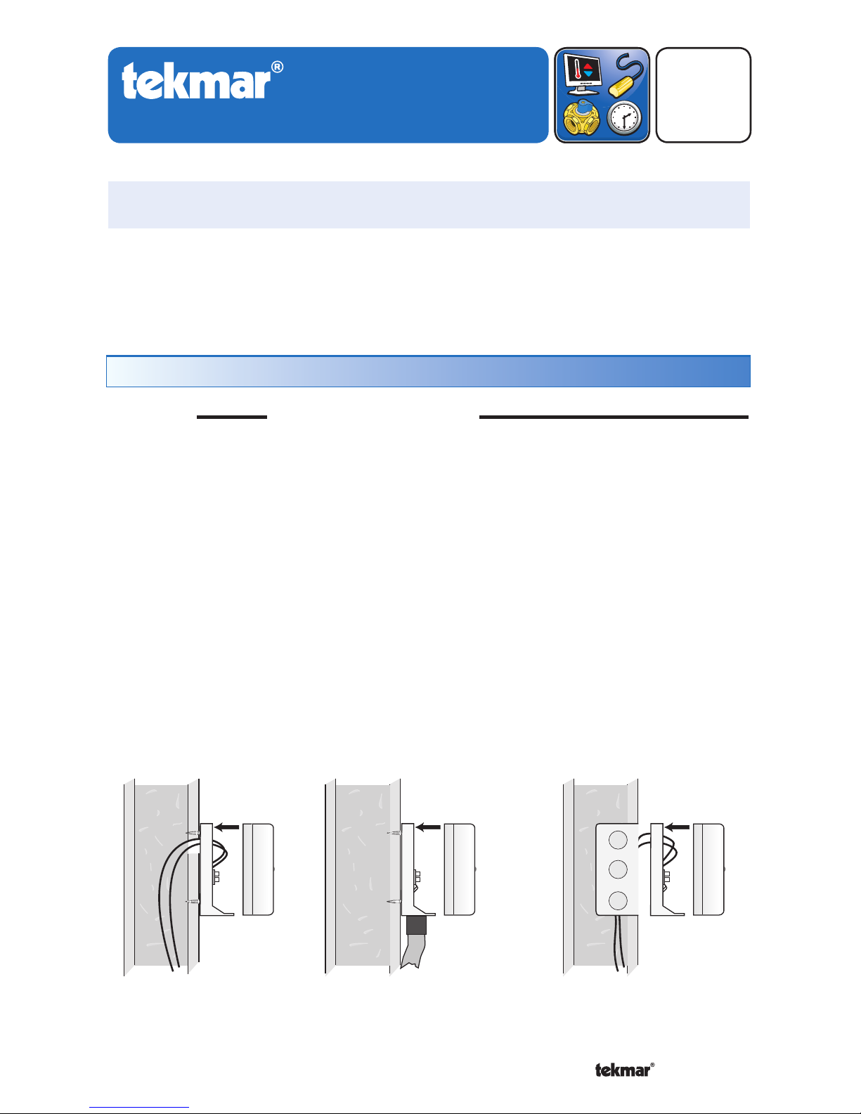
STEP ONE
MOUNTING THE SENSOR
NOTE: The temperature sensor (thermistor) is built into the 070 enclosure.
• Remove the screw and pull the front cover off the sensor enclosure.
• The 070 can either be mounted directly onto a wall or a 2” x 4” electrical box. When
the 070 is wall mounted, the wiring should enter through the back or bottom of the
enclosure. Do not mount the 070 with the conduit knockout facing upwards as rain
could enter the enclosure and damage the sensor.
• In order to prevent heat transmitted through the wall from affecting the sensor reading, it may be necessary to install an insulating barrier behind the enclosure.
• The 070 should be mounted on a wall which best represents the heat load on the
building (a northern wall for most buildings and a southern facing wall for buildings
with large south facing glass areas). The 070 should not be exposed to heat sources
such as ventilation or window openings.
• The 070 should be installed at an elevation above the ground that will prevent
accidental damage or tampering.
Sensor with bottom
entry wiring
Sensor with rear
entry wiring
Sensor mounted
onto 2" x 4"
electrical box
Installation - Outdoor Sensor 070
© 2012 070_D - 12/12
2 of 4
A Watts Water Technologies Company
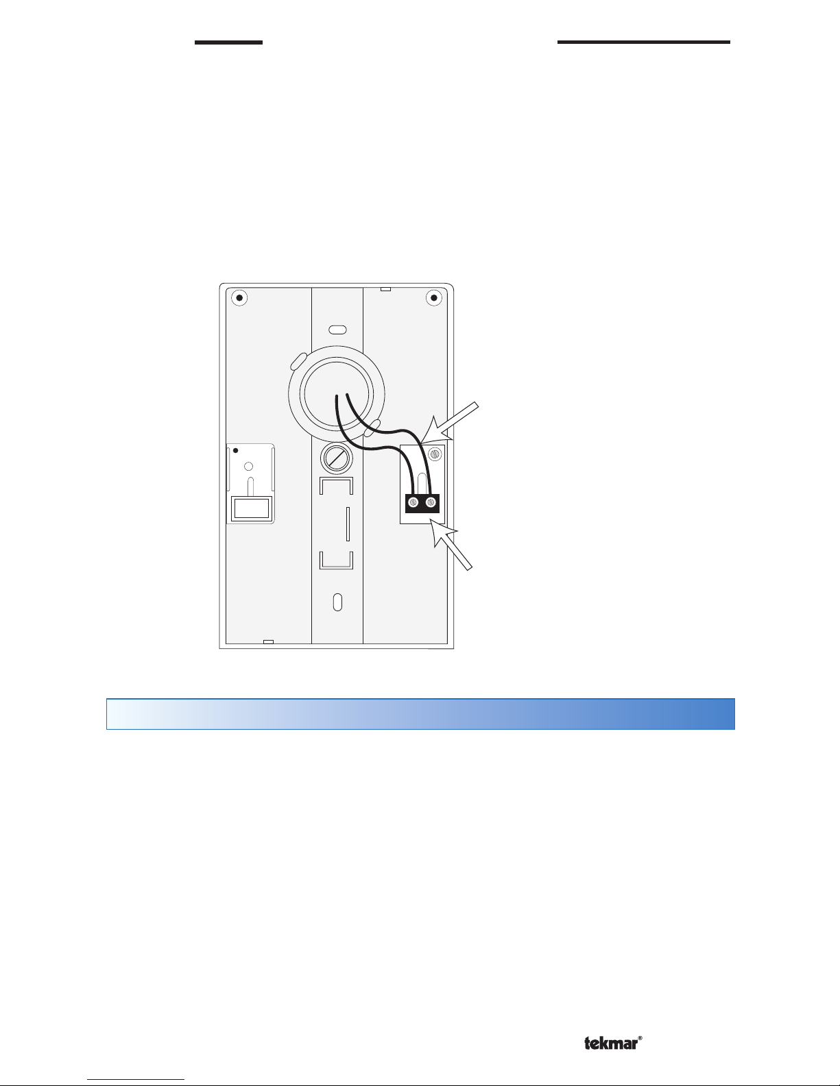
STEP TWO
WIRING AND TESTING THE SENSOR
• Connect 18 AWG or similar wire to the two terminals provided in the enclosure and
run the wires from the 070 to the control. Do not run the wires parallel to telephone
or power cables. If the sensor wires are located in an area with strong sources of
electromagnetic interference (EMI), shielded cable or twisted pair should be used
or the wires can be run in a grounded metal conduit. If using shielded cable, the
shield wire should be connected to the Com terminal on the control and not to earth
ground.
•
Follow the sensor testing instruction in this brochure and connect the wires to the
control.
• Replace the front cover of the sensor enclosure.
A good quality test meter capable of measuring up to 5,000 k (1 k = 1000) is required to
measure the sensor resistance. In addition to this, the actual temperature must be measured
with either a good quality digital thermometer, or if a thermometer is not available, a second
sensor can be placed alongside the one to be tested and the readings compared.
First measure the temperature using the thermometer and then measure the resistance of
the sensor at the control. The wires from the sensor must not be connected to the control
while the test is performed. Using the chart on the following page, estimate the temperature
measured by the sensor. The sensor and thermometer readings should be close. If the test
meter reads a very high resistance, there may be a broken wire, a poor wiring connection
or a defective sensor. If the resistance is very low, the wiring may be shorted, there may
be moisture in the sensor or the sensor may be defective. To test for a defective sensor,
measure the resistance directly at the sensor location.
Do not apply voltage to a sensor at any time as damage to the sensor may result.
Wires from outdoor
sensor to control’s
outdoor sensor and
sensor common
terminals
Sensor is built into
the enclosure
Sensor Testing Instructions
 Loading...